EP2489832A2 - Hand-Werkzeugmaschine mit einem Lamellenmotor und einem Lagerdeckel - Google Patents
Hand-Werkzeugmaschine mit einem Lamellenmotor und einem Lagerdeckel Download PDFInfo
- Publication number
- EP2489832A2 EP2489832A2 EP11010206A EP11010206A EP2489832A2 EP 2489832 A2 EP2489832 A2 EP 2489832A2 EP 11010206 A EP11010206 A EP 11010206A EP 11010206 A EP11010206 A EP 11010206A EP 2489832 A2 EP2489832 A2 EP 2489832A2
- Authority
- EP
- European Patent Office
- Prior art keywords
- bearing cap
- bearing
- rotor
- rotation
- machine tool
- Prior art date
- Legal status (The legal status is an assumption and is not a legal conclusion. Google has not performed a legal analysis and makes no representation as to the accuracy of the status listed.)
- Granted
Links
Images


Classifications
-
- F—MECHANICAL ENGINEERING; LIGHTING; HEATING; WEAPONS; BLASTING
- F01—MACHINES OR ENGINES IN GENERAL; ENGINE PLANTS IN GENERAL; STEAM ENGINES
- F01C—ROTARY-PISTON OR OSCILLATING-PISTON MACHINES OR ENGINES
- F01C1/00—Rotary-piston machines or engines
- F01C1/30—Rotary-piston machines or engines having the characteristics covered by two or more groups F01C1/02, F01C1/08, F01C1/22, F01C1/24 or having the characteristics covered by one of these groups together with some other type of movement between co-operating members
- F01C1/34—Rotary-piston machines or engines having the characteristics covered by two or more groups F01C1/02, F01C1/08, F01C1/22, F01C1/24 or having the characteristics covered by one of these groups together with some other type of movement between co-operating members having the movement defined in group F01C1/08 or F01C1/22 and relative reciprocation between the co-operating members
- F01C1/344—Rotary-piston machines or engines having the characteristics covered by two or more groups F01C1/02, F01C1/08, F01C1/22, F01C1/24 or having the characteristics covered by one of these groups together with some other type of movement between co-operating members having the movement defined in group F01C1/08 or F01C1/22 and relative reciprocation between the co-operating members with vanes reciprocating with respect to the inner member
- F01C1/3441—Rotary-piston machines or engines having the characteristics covered by two or more groups F01C1/02, F01C1/08, F01C1/22, F01C1/24 or having the characteristics covered by one of these groups together with some other type of movement between co-operating members having the movement defined in group F01C1/08 or F01C1/22 and relative reciprocation between the co-operating members with vanes reciprocating with respect to the inner member the inner and outer member being in contact along one line or continuous surface substantially parallel to the axis of rotation
- F01C1/3442—Rotary-piston machines or engines having the characteristics covered by two or more groups F01C1/02, F01C1/08, F01C1/22, F01C1/24 or having the characteristics covered by one of these groups together with some other type of movement between co-operating members having the movement defined in group F01C1/08 or F01C1/22 and relative reciprocation between the co-operating members with vanes reciprocating with respect to the inner member the inner and outer member being in contact along one line or continuous surface substantially parallel to the axis of rotation the surfaces of the inner and outer member, forming the working space, being surfaces of revolution
-
- F—MECHANICAL ENGINEERING; LIGHTING; HEATING; WEAPONS; BLASTING
- F01—MACHINES OR ENGINES IN GENERAL; ENGINE PLANTS IN GENERAL; STEAM ENGINES
- F01C—ROTARY-PISTON OR OSCILLATING-PISTON MACHINES OR ENGINES
- F01C21/00—Component parts, details or accessories not provided for in groups F01C1/00 - F01C20/00
- F01C21/10—Outer members for co-operation with rotary pistons; Casings
- F01C21/104—Stators; Members defining the outer boundaries of the working chamber
- F01C21/108—Stators; Members defining the outer boundaries of the working chamber with an axial surface, e.g. side plates
-
- F—MECHANICAL ENGINEERING; LIGHTING; HEATING; WEAPONS; BLASTING
- F04—POSITIVE - DISPLACEMENT MACHINES FOR LIQUIDS; PUMPS FOR LIQUIDS OR ELASTIC FLUIDS
- F04C—ROTARY-PISTON, OR OSCILLATING-PISTON, POSITIVE-DISPLACEMENT MACHINES FOR LIQUIDS; ROTARY-PISTON, OR OSCILLATING-PISTON, POSITIVE-DISPLACEMENT PUMPS
- F04C2230/00—Manufacture
- F04C2230/60—Assembly methods
- F04C2230/603—Centering; Aligning
Definitions
- the invention relates to a hand-held machine tool, in particular grinding, polishing or screwing, with a pneumatic vane motor, wherein the vane motor has a stator housing having a rotor chamber in which a rotatably provided with a motor shaft rotor is rotatably received, wherein the rotor is a rotor body and the lamellae of the rotor body to a peripheral wall of the rotor chamber has movably mounted lamellae, and wherein the stator housing comprises a circumferential wall having peripheral body and at least one separate from the peripheral body and the rotor chamber frontally occluding bearing cap, wherein the motor shaft protrudes with a longitudinal end in front of the rotor chamber and on which at least one bearing cap is rotatably mounted about an axis of rotation, wherein the at least one bearing cap rests with an end face facing the rotor chamber on an end face of the peripheral wall facing the at least one bearing cap ,
- lamellar motors are well suited because they are compact with high power delivery.
- a pneumatic vane motor is in DE 39 39 096 A1 or DE 102 59 006 B described.
- oiled compressed air is usually used to operate such hand-held machine tools or their pneumatic motors, which thus has a lubricating function.
- lubrication of the vane motor is difficult and small tolerances are advantageous.
- a hand-held power tool of the type mentioned above characterized in that the at least one bearing cap is centered relative to the peripheral body with respect to the axis of rotation of the motor shaft by a separate from the at least one bearing cap and the peripheral body holding device act on at least two relative to the rotational axis to each other with respect to the rotational angle offset sides in the direction of the axis of rotation acting on the bearing cap and the peripheral wall.
- bearing cap unlike conventional pneumatic motors, is not screwed, for example, on the face side in the sense of centering, which results in centering problems can, but is centered with an external, peripherally acting on the bearing cap and peripheral body, separate holding device. Due to the angular displacement, for example, in each case 60 ° between the individual contact points, a centering of radially outward in the direction of the axis of rotation is effected.
- the holding device holds the bearing cap in a clamping fit on the peripheral body, in particular without an additional screw connection. But it is also possible that an additional screw is present, e.g. to effect a frontal support of the bearing cap on the peripheral body, without affecting the centering of the bearing cap by the holding device.
- the holding device may comprise, for example, a sleeve or a ring, which bears against the outer circumference of the at least one bearing cap and the peripheral body.
- the ring or sleeve expediently does not extend over the entire longitudinal length of the peripheral body (i.e., the length extending in the direction of the axis of rotation), but only over the respective longitudinal end portion of the peripheral body.
- An embodiment of the invention may provide that there are no further holding means between the peripheral body and the bearing cap, e.g. Bolts, pins or the like. Preferably then no bolts or pins are present, which extend in the direction of the axis of rotation.
- this expediently has a transverse to the axis of rotation of the rotor with respect to the peripheral body and / or the bearing cap Such game that the holding device can develop their centering effect.
- the bolt, pin or projection acts advantageously as a rotation against a relative rotation of the bearing cap to the peripheral body.
- a projection adapted for installation in a holding or over-housing, e.g. the housing of the hand machine tool, serves.
- the projection is expediently arranged on the peripheral body and / or formed by the aforementioned pin or bolt.
- a preferred variant of the invention provides that the bolt or projection arranged on the circumferential body penetrates the bearing cap and protrudes in front of it.
- both bearing caps that is to say an upper and a lower bearing cap, are fastened to the peripheral body with a holding device according to the invention.
- one of the bearing cap forms an integral part of the stator, that is, for example, is integral with the peripheral wall, while the other bearing cap is removable from the rest of the housing, but is centered with the holding device according to the invention.
- the outer circumference of the at least one bearing cap and the outer circumference of the peripheral body are expediently aligned with one another in the region of the holding device.
- there is advantageously no step between the two outer peripheral contours of the at least one bearing cap and the peripheral body although this is of course possible in an alternative embodiment of the invention.
- the inner peripheral contours of the holding device in the region of the outer circumference of the at least one bearing cap and the peripheral body naturally fit with the outer peripheral contours of the at least one bearing cap and the peripheral body.
- the inner peripheral contours of the holding device are also aligned so that the holding device has, for example, a continuous or a stepped inner peripheral contour.
- the holding device is angled, that is, it has a first, applied to the outer periphery of the at least one bearing cap and the peripheral body centering leg, and a second leg which is supported on a side remote from the peripheral body end side of the bearing cap and this force towards the peripheral body.
- the holding device thus pulls the bearing cap in the direction of the peripheral body.
- the holding device may comprise one or more stages. For example, a first step section for engagement with the peripheral body, a second step for engagement with the at least one bearing cap may be provided.
- first and / or the second leg in the above embodiment may each have stepped portions. If, for example, a step is provided on an end face of the at least one bearing cap facing away from the peripheral housing, it is advantageous if the associated second leg is likewise stepped, so that it rests positively on the step sections of the bearing cover. The same naturally also applies to circumferential surfaces on the peripheral body and / or on the bearing cap, where a stepped seat of each associated portion of the holding device is advantageous.
- the holding device holds the bearing cap and / or the peripheral body with individual holding projections, which counteracts, for example, a static overdetermination.
- the holding device is attached with a press fit to the at least one bearing cap.
- a unit of bearing cap and holding device can be formed, which is ready for mounting on the peripheral body.
- the holding device expediently has a transition fit.
- the vane motor is formed as a total package, that is, the at least one bearing cap, preferably both bearing caps are fixedly secured by means of the holding device according to the invention on the peripheral body, so that the vane motor as a whole or as a package in a machine housing Hand machine tool can be installed.
- An end face of the peripheral wall and / or one of the peripheral wall facing frontal annular surface of the at least one bearing cap are preferably planar surfaces.
- the frontal Ring surface is then flat on the front side of the peripheral wall, which is also flat to.
- the at least one bearing cap has an end face that extends over its entire end face facing the rotor chamber and that is substantially planar or even completely flat.
- the bearing cap can thus have a total of a plane surface, in particular a ground plan surface, which not only allows a plan, fit on the front side annular surface or the peripheral wall, but also a plane, low friction loss causing surface in the rotor chamber.
- the bearing cap is also flat in the area of the rotor chamber.
- the lamella is quasi flowed behind, so that it moves in the direction of the outer circumference of the rotor or to the peripheral wall of the rotor chamber and sealingly abuts there.
- An airflow outlet can also be arranged on the at least one bearing cap, through which the air from the rotor chamber to a bearing arranged on the bearing cap can flow. This cools the bearing.
- the bearing is, for example, an eccentric bearing.
- the bearing body expediently has a bearing receptacle which is eccentric to the axis of rotation of the motor and in which a pivot bearing for rotatably supporting a tool receptacle is arranged.
- the tool holder is eccentric to the pivot bearing.
- the rotor chamber is expediently eccentric to a center axis of the stator housing, that is to say that an inner circumference or the circumferential wall of the rotor chamber and an outer circumference of the circumferential body or of the circumferential section of the stator housing are eccentric relative to one another.
- At least one of the lamellae and / or the stator housing and / or the rotor body at least partially made of a non-metallic material, wherein the non-metallic material comprises or forms a graphite material and / or a ceramic material ,
- stator housing and / or the rotor body.
- non-metallic materials which are not plastics, which have the least possible wear with high dimensional accuracy, even when heated.
- non-metallic materials are particularly suitable graphite, ceramic or the like.
- the non-metallic material comprises an electro-graphite material and / or a carbon graphite material or is formed by electro-graphitic material or carbon graphite material or the non-metallic material comprises a mixture or combination of materials, each containing electro-graphite and / or a carbon graphite material.
- non-metallic material which is used, for example, for the rotor, for one or more lamellae or for the stator housing, in particular the peripheral wall, is impregnated.
- resin is suitable for the impregnation of the non-metallic material.
- non-metallic material which comprises or is in particular electro-graphite and / or carbon graphite, for the rotor body.
- stator housing in particular the peripheral wall, or even the rotor body made of a metal material.
- stator housing in particular the peripheral wall of the rotor chamber, or even one or both of the rotor chamber frontally occluding bearing cover made of steel, for example, chromium-molybdenum steel exist.
- thermal expansion coefficients of the non-metallic material and the metal material approximately equal, for example, about the same or not more than a factor of 2 to 3 different.
- the lamellae it is advantageous if they consist of a laminate material, for example of a textile fabric which is impregnated or bonded with phenolic resin, of graphite or of a slide-modified plastic.
- a laminate material for example of a textile fabric which is impregnated or bonded with phenolic resin, of graphite or of a slide-modified plastic.
- electro-graphite is particularly advantageous. It is understood that not all lamellae must be made of the same material, although this is advantageous.
- the arrangement is such that the rotor in the operation of the vane motor in relation to the stator housing, in particular the Peripheral wall, more heated, so that a thermal elongation of the motor and the stator housing, in particular along the axis of rotation, about the same.
- the rotor for example, due to a tool bearing and / or a motor bearing, which is arranged on a bearing plate or a bearing cap, heated more than the housing.
- an eccentric bearing with a tool holder, for example for a sanding pad or a polishing plate.
- the eccentric bearing heats the rotor during operation the hand machine tool relatively strong, so that the rotor expands more than the housing even with a lower coefficient of thermal expansion, so that in sum, the longitudinal extent of the rotor (in the direction of the axis of rotation) and the stator are approximately equal.
- Non-metallic materials can have a certain brittleness, so they are less tough or tensile than, for example, steel or certain plastics.
- the following measure is advantageous in order nevertheless to realize a reliable, the rotor body mechanically low loading rotary drive of the motor shaft.
- the rotor body has, for example, a shaft receptacle for the motor shaft, which has a rotational drive cross-sectional contour.
- a rotary driving cross-sectional contour of the motor shaft corresponds.
- the two rotational driving cross-sectional contours are mutually suitably polygonal, for example, pentagonal, hexagonal, triangular or the like, so that the motor shaft is rotatably received in the rotor body.
- the motor shaft is received in the shaft recording floating or with a certain play. As a result, voltages between the motor shaft and the rotor body are reduced or even avoided.
- the lamellae are each arranged on a flat side between corner regions of the rotary driving cross-sectional contours. As a result, the load on the rotary drive is particularly low.
- a centering section with a particularly round cross-sectional contour.
- the motor shaft is advantageous flat in the region of the centering of the shaft recording in the sense of centering fitting.
- the function of the rotary driving is realized by the rotary driving cross-sectional contours, while the centering takes place at a separate portion of the shaft receiving or the motor shaft.
- the shaft receiver is slightly wider than the outer circumference of the motor shaft, so that it can move slightly in the area of this free space, that is, transversely to the axis of rotation.
- the motor shaft can pivot about the centering a little, albeit advantageous to a very small extent.
- the rotor has so transverse to the axis of rotation a certain pivotal play or rotational play, which counteracts a tension and thus a mechanically possibly too high load of the rotor body - or the motor shaft.
- the rotor a total of the vane motor as such, a short, compact length, that is, he builds relatively short and has a relatively large diameter.
- a palm rest may be provided above the vane motor on the machine housing of the hand-held machine tool and the hand placed there close to the driven tool.
- the machine does not build particularly high in the engine, but is quite flat, which is ergonomically advantageous because the Hand tool machine leading the operator's hand close to the tool and thus, for example, difficult to access places a workpiece to be processed with the hand-held machine tool, are easily accessible.
- the multi-disk motor according to the invention can be operated without oil, that is, with non-oiled compressed air.
- the rotor is relatively light.
- the rotor chamber is at least partially lined with the non-metallic material, for example in the region of the peripheral wall, while a base body consists of, for example, metal, in particular chromium-molybdenum steel.
- a casting material is of course readily possible.
- a rotor body of graphite, in particular of electro-graphite and / or carbon graphite, in practice also has the advantage that the lamellae received in or on the rotor wear little.
- a so-called Kolkverschl yield, which could occur in bearing receptacles for the slats, is low in the engine according to the invention. Even at the transition region between an outer circumference of the rotor body and the slats no or only a slight wear is observed.
- the bearing receivers for the slats expediently extend radially to the axis of rotation. It is also possible that are provided obliquely to the rotation axis oriented bearing mounts.
- the fins of the multi-disc motor are relatively narrow, at least weight-optimized, which also contributes to low wear.
- a hand machine tool 10 forms a grinding or polishing machine.
- a plate tool 12 is rotatably arranged on a housing 11 of the hand-held machine tool 10.
- the housing 11 has a handle portion 13 and a motor portion 14.
- a vane motor 15 is added, which can drive the plate tool 12 via its motor shaft 16.
- the hand-held power tool 10 is a pneumatic machine, that is to say operated with compressed air.
- This compressed air can flow into the housing 11 via a compressed air connection 17.
- the compressed air connection 17 is arranged at the rear on the handle portion 13, that is, it protrudes to the rear before it.
- a compressed air line advantageously a multi-media line, are connected, which brings not only compressed air to the hand-machine tool 10, but also exhaust air and / or conveying dust laden air away from the hand machine tool.
- dust-laden air can be led away from the plate tool 12 via a dust channel 18, which extends below the handle portion 13.
- the compressed air flowing through the compressed-air connection 17 flows via a compressed-air channel 19 of the housing 11.
- the compressed air channel 19 leads to a valve 20 which has a valve body 21 and a closing spring 22.
- the closing spring 22 leads in the direction of a closed position of the valve 20, that is, on a valve seat 23. In this direction also acts from the compressed air channel 19 in the direction of valve 20 flowing compressed air. The compressed air thus acts in the sense of closing.
- the valve 20 can be opened in a manner known per se by means of a handle 24.
- the handle 24 is pivotally mounted in the region of the handle portion 13 with a pivot bearing 25.
- a free end of the handle 24 is located above the vane motor 15, that is, in the region of a palm rest above the motor section 14 or on the motor section 14.
- the actuator 26 projects upwardly in front of the housing 11 and is motion coupled to the handle 24. If this is pressed down, he also presses the actuator 26 down so that the actuator 26 lifts the valve body 21 from the valve seat 23. Between the actuator 26 and the actuating projection 27, a wedge or bevel gear is present.
- valve 20 When the valve 20 is opened, the compressed air flows out of the valve 20 through a channel 28 and into a compressed air inlet of a stator housing 30 of the multi-disk motor 15.
- the rotor chamber 31 is provided in a circumferential body 33 having a circumferential body 32.
- the peripheral body 32 is closed at the front by an upper bearing cap 34 and a lower bearing cap 35.
- a rotor 36 is rotatably received about a rotation axis 37.
- Lamellae 39 are movably mounted on a rotor body, namely accommodated in lamella receptacles 40.
- the fins 39 are plate-like.
- the lamella receptacles 40 are configured as slots or grooves and are open on an outer periphery 41 of the rotor body 38. Thus, therefore, the fins 39, which are quasi stuck in the lamellae receptacles 40, radially outward in the direction of an inner circumference of the rotor chamber 31, that is to the peripheral wall 33, are moved.
- the rotor body 38 has a cylindrical shape with opposite end faces 42, 43 and a cylinder jacket outer circumference 41.
- the lamella receptacles 40 are open to the outer periphery 41.
- the lamella receptacles 40 extend from the one end face 42 to the other end face 43, so are open at the respective end faces 42, 43.
- the air inlet 29 is provided on an outer periphery of the peripheral body 32. From the air inlet 29, the compressed air flows through a channel 103 to a for rotationally driving the rotor 36 provided inlet portion 104 and an inflow 45 on the upper bearing cap 34 and / or to an inflow 45 on the lower bearing cap 35, via which or the compressed air in the direction of a center of the bearing cap 34 and / or bearing cap 35 can flow.
- a first section 46 of the inflow channel 45 which is designed as an air supply recess on the bearing cap 35, thus leads in the direction of the center of this bearing cap 35.
- the section 46 is for example rectilinear.
- the inflow passage 45 is open to the rotor body 38, in particular the lamella receptacles 40, at least in the region of a distribution section 47 adjoining the section 46.
- air flowing through the distribution section 47 can flow into the lamella receptacle 40 which is located closest to the air inlet 29.
- the lamella accommodated in this lamella receptacle 40 for example the lamella 39a in the plan view, is according to FIG FIG. 10 , Adjusted radially outward in the direction of the peripheral wall 33, so that it bears against this with its flat face substantially pressure-tight.
- the rotation axis 37 is eccentric to a center axis 48 of the cylindrical rotor chamber 31.
- the air flowing behind the fin 39a expands by rotation of the rotor 36, which generates the aforementioned torque.
- the lamella 39b already protrudes further in front of the outer circumference 41 of the rotor body 38 than the lamella 39a.
- this space decreases again, that is, for example, the lamellae 39c, 39d and 39e are displaced again in the direction of the axis of rotation 37 back, that is, penetrate deeper into the lamellae holders 40.
- the fins 39c, 39d and 39e located air flow through a discharge channel 49 on the bearing cap 34 and / or on the bearing cap 35 in the direction of Heilausströmauslasses 50 of the stator 30, so leave the rotor chamber 31.
- the Heilausströmauslass 50 communicates with a discharge channel 51 of the housing 11.
- the discharge channel 51 opens at the rear of the housing 11 in the region of the compressed-air connection 17, so it can be connected to the not shown Mehrmedienschlauch.
- the rotor 36 rotates very quickly, that is, its working speed is in the range between 8000 and 12000 revolutions per minute, but may also be slightly higher, for example 13000 to 15000 revolutions. Thus, it is therefore expedient if the rotor 36 runs easily, that is, the friction losses are low. In addition, it is advantageous if a high air-tightness between the upper and lower end faces 42, 43 and their facing end faces 52, 53 of the bearing cap 34, 35 is present. Furthermore, it is advantageous if the slats 39 easily slide in the slats receptacles 40, thereby resulting in low friction losses and the slats 39 always tight against the peripheral wall 33.
- the rotor body 38 expediently consists of an electro-graphite and / or a carbon graphite or comprises a material mixture or material combination containing electro-graphite and / or carbon graphite.
- it is lightweight and has in particular in the field of lamellae 40 optimal sliding properties.
- the fins 39 themselves are suitably made of a very fine cotton fabric laminate bonded with phenolic resin.
- the lamellae 39 and / or the inner surfaces of the lamella receptacles 40 are coated with PTFE. This reduces the sliding friction and thus also the wear.
- the liner itself that is, the peripheral body 32 is suitably made of steel. Particularly preferred is chromium-molybdenum steel.
- the bearing caps 34, 35 are suitably made of a metal material, in particular the aforementioned steel. This material mix is particularly well suited for the operation of the multi-disc motor 15 with both oiled and non-lubricated compressed air. In any case, optimal sliding properties are achieved.
- the motor shaft 16 protrudes with bearing ends 56, 57 in front of the rotor chamber 31.
- the bearing ends 56, 57 are rotatably mounted with pivot bearings 58, 59.
- the pivot bearings 58, 59 are received in bearing receivers 60, 61 on the bearing caps 34, 35.
- the rotary bearings 58, 59 are, for example, ball bearings, wherein, of course, also needle loader, pollen storage or the like are readily possible.
- a plain bearing is also conceivable in principle.
- the motor shaft 16 penetrates openings 62, 63 on the bearing caps 34, 35.
- the pivot bearing 58 is supported for example on a step of the motor shaft 16, which is present between the bearing end 56 and a free space portion 64 of the motor shaft 16. At the side facing away from the free space portion 64 side of the pivot bearing 58 is held by a retaining ring 65 which is fixed to the bearing end 56.
- the free space section 64 penetrates the (upper) bearing cap 34 in the region of its opening 62.
- the motor shaft 16 is normally not located in the region of the centering 67 at the shaft receiving 44 or its inner circumference, so has a certain amount of play.
- centering sections 67, 68 are, for example, cylindrical. Of course, other geometries would be possible, for example triangular. Indeed It is advantageous that in the region of the centering sections 67, 68 no rotational drive takes place, but in the region of rotary driving cross-sectional contours 69, 70 of the motor shaft 16 and the shaft seat 44th
- the rotary driving cross-sectional contours 69, 70 are approximately pentagonal in cross-section, for example, wherein the corner regions are expediently rounded. Thus, therefore, the flat sides 71, 72 of the rotary driving cross-sectional contours 69, 70 substantially flat against each other. It is expedient if only little power transmission takes place at the corner regions. Also in the region of the rotary driving cross-sectional contours 69, 70 expediently a certain clearance between the motor shaft 16 and the shaft receiving 44 is present, so that the motor shaft 16 in the shaft receiving 44 has a certain pivotal play transverse to the axis of rotation 37. The motor shaft 16 is accommodated in a manner floating in the shaft receiving 44, which counteracts tension. In particular, the existing example of metal, especially steel, existing motor shaft 16, the rotor body 38 less tension, which could lead to damage, especially in view of the relatively brittle non-metal from which the rotor body 38 according to the invention.
- the centering sections 67, 68 are arranged approximately longitudinally (with respect to the axis of rotation 37) between the bearing caps 34, 35.
- the motor shaft 16 can tilt slightly transverse to the axis of rotation 37, to compensate for centering errors, for example with respect to the openings 62, 63, the pivot bearing 58, 59 or the like. A uniform stress distribution is thus possible.
- a motor shaft and otherwise on the rotor body of an engine according to the invention with a smaller or low voltage is fastened.
- the motor shaft is an expandable shaft, a shaft with a slot, a tension shaft or the like.
- the rotary driving cross-sectional contour 69 of the motor shaft 16 is followed by a flange 73, which is arranged in the opening 63 of the bearing cap 35. Between the outer periphery of the flange 73 and the opening 63, a seal 74 is expediently provided. However, it can also be provided that air can flow out of the rotor chamber 31 in the region of the rotary bearing 58 or 59 in order to cool the respective rotary bearing 58, 59.
- a bearing body 75 is arranged.
- the bearing body 75 is expediently pressed onto the motor shaft 16, wherein a screw or the like is possible.
- the bearing body 75 has an axis of rotation 37 eccentric bearing receptacle 76 in which a pivot bearing 77 is received.
- the pivot bearing 77 supports a tool holder 78 to which the plate tool 12 can be fastened, for example by means of a screw 79.
- the tool holder 78 rotates about an eccentricity 80 with respect to the axis of rotation 37.
- the hand tool 10 thus forms a Exzentertellerschleifer or an eccentric disc polisher.
- the plate tool 12 does not assume the speed of the multi-disc motor 15, it is braked in a conventional manner, for example by a seal 81, which acts from above (frontally) on the plate tool 12 braking.
- the two bearing bodies each have plates 82, whose rotor chamber 31 facing end face 52, 53 is designed as a plane surface.
- the plates 82 are thus configured from its center (openings 62, 63) forth radially outwardly as a flat surface, so that the end faces 52, 53 are at least in the region of the rotor chamber 31 plan.
- the bearing receivers 60, 61 are arranged at the side remote from the end faces 52, 53 sides of the bearing receivers 60, 61.
- the bearing receivers 60, 61 respectively project in front of these side facing away from the end face 52, 53 side annular walls 83, in which the pivot bearings 58, 59 are respectively held.
- Adapters may be provided on the annular walls 83, for example for a ring seal 84 between the annular wall 83 and the pivot bearing 58.
- Planar surfaces 85 are thus provided on the end faces 52, 53, in particular also in a contact region 86, with which the end faces 52, 53 abut against end faces 87 of the circumferential wall 33 in each case.
- the end faces 87 are annular, as well as the abutment areas 86.
- the bearing caps 34, 35 frontally plan to rest with the peripheral wall 33. Manufacturing this is optimal, namely because the end faces 87 and the flat surfaces 85 can be edited plan and just. Nevertheless, an optimal hold of the bearing caps 34, 35 realized on the peripheral body 32.
- the bearing caps 34, 35 are held centering by holding devices 90 on the peripheral body 32.
- the holding devices 90 comprise a retaining ring 91 with a first leg 92 and a second leg 93.
- the first leg 92 and the second leg 93 are perpendicular to each other.
- the first leg 92 has a centering function, that is, it is on an outer periphery 88 of the bearing cap 34 or the bearing cap 35 and an outer periphery 89 of the rotor body 38 circumferentially in the sense of centering. In principle, the first leg 92 would already be sufficient to fulfill this centering function.
- the outer periphery 88 and the outer periphery 89 are aligned with each other.
- the second leg 93 rests against the end face 94, 95 of the bearing cap 34, 35 facing away from the rotor chamber 31 and thus holds the respective bearing cap 34, 35 on the peripheral body 32.
- a dowel pin 98 projects in front of the stator housing 30 and is received in a receptacle 99 in the motor mount 96, so that the vane motor 15 in the correct angle is mountable in the motor mount 96, so that the air inlet 29 can communicate with the channel 28.
- the dowel pin 98 is inserted into the peripheral body 32, expediently pressed in and / or received without play in the peripheral body 32, and penetrates the bearing cap 34 and / or 35, which has a bore or passage 105 for this purpose.
- An inner cross section of the passage 105 is larger than an outer cross section of the dowel pin 98, which is thus received with play in the passage 105. Therefore, the retainer 90 can hold the bearing cap 34 and / or 35 centering on the peripheral body 32.
- the dowel pin 98 forms an anti-rotation for the bearing cap 34 and / or 35 relative to the peripheral body 32. It is expediently provided that this rotation is no longer required if the retaining ring 97 holds the vane motor 15 in the motor mount 96, in particular braced.
- the leg 93 For receiving the second leg 93 is at the end faces 94, 95 of the bearing cap 34, 35 each have a level 100 available. Thus, the leg 93 is not or only slightly before the upper or lower end face 94, 95 of the bearing cap 34, 35 before. Between a middle outer periphery 101 of the peripheral body 32 and the respective outer periphery 89, a further step 102 for the leg 92 is provided.
Landscapes
- Engineering & Computer Science (AREA)
- Mechanical Engineering (AREA)
- General Engineering & Computer Science (AREA)
- Connection Of Motors, Electrical Generators, Mechanical Devices, And The Like (AREA)
- Constituent Portions Of Griding Lathes, Driving, Sensing And Control (AREA)
Abstract
Description
- Die Erfindung betrifft eine Hand-Werkzeugmaschine, insbesondere Schleifgerät, Poliergerät oder Schraubgerät, mit einem pneumatischer Lamellenmotor, wobei der Lamellenmotor ein Statorgehäuse aufweist, das eine Rotorkammer aufweist, in der ein mit einer Motorwelle versehener Rotor drehbar aufgenommen ist, wobei der Rotor einen Rotorkörper und an Lamellenaufnahmen des Rotorkörpers zu einer Umfangswand der Rotorkammer hin beweglich gelagerte Lamellen aufweist, und wobei das Statorgehäuse einen die Umfangswand aufweisenden Umfangskörper sowie mindestens einen von dem Umfangskörper separaten und die Rotorkammer stirnseitig verschließenden Lagerdeckel umfasst, wobei die Motorwelle mit einem Längsende vor die Rotorkammer vorsteht und an dem mindestens einen Lagerdeckel um eine Drehachse drehbar gelagert ist, wobei der mindestens eine Lagerdeckel mit einer der Rotorkammer zugewandten Stirnseite auf einer dem mindestens einen Lagerdeckel zugewandten Stirnseite der Umfangswand aufliegt.
- Zum Antreiben pneumatischer Hand-Werkzeugmaschinen, beispielsweise Schleifgeräten, Poliergeräten oder Schraubern, eignen Lamellenmotoren gut, da sie bei großer Leistungsentfaltung kompakt sind. Beispielsweise ist ein pneumatischer Lamellenmotor in
DE 39 39 096 A1 oderDE 102 59 006 B beschrieben. - Je geringer die Toleranzen des Lamellenmotors sind, insbesondere wenn er sich erwärmt, desto kleiner ist auch der Druckluftverbrauch. Daher sind an die Qualität der verwendeten Materialien, die Fertigungsgenauigkeit und dergleichen in zunehmendem Maße höhere Anforderungen zu stellen.
- Darüber hinaus wird in der Regel zum Betrieb solcher Hand-Werkzeugmaschinen beziehungsweise deren pneumatischen Motoren geölte Druckluft verwendet, die also eine Schmierfunktion hat. Wenn jedoch neueren Anforderungen folgend auch ungeölte Druckluft verwendet werden soll, ist die Schmierung des Lamellenmotors schwierig und kleine Toleranzen vorteilhaft.
- Es ist daher die Aufgabe der vorliegenden Erfindung, einen Lamellenmotor und eine mit einem Lamellenmotor ausgestattete Hand-Werkzeugmaschine bereitzustellen, wobei der Lamellenmotor bei möglichst geringem Luftverbrauch effizient arbeiten soll, insbesondere auch wahlweise mit geölter und ungeölter Druckluft betrieben werden kann.
- Zur Lösung der Aufgabe ist bei einer Hand-Werkzeugmaschine der eingangs genannten Art vorgesehen, dadurch gekennzeichnet, dass der mindestens eine Lagerdeckel relativ zum Umfangskörper bezüglich der Drehachse der Motor-welle durch eine von dem mindestens einen Lagerdeckel und dem Umfangskörper separate Halteeinrichtung zentriert ist, die an mindestens zwei bezogen auf die Drehachse zueinander drehwinkelversetzten Seiten in Richtung der Drehachse wirkend an dem Lagerdeckel und der Umfangswand anliegt.
- Ein Grundgedanke ist es, dass der Lagerdeckel anders als bei üblichen pneumatischen Motoren nicht z.B. stirnseitig im Sinne eines Zentrierens verschraubt wird, was Zentrierprobleme ergeben kann, sondern mit einer externen, umfangsseitig am Lagerdeckel und Umfangskörper angreifenden, separaten Halteeinrichtung zentriert ist. Durch den Drehwinkelversatz, beispielsweise jeweils 60° zwischen den einzelnen Anlagestellen, wird eine Zentrierung von radial außen her in Richtung der Drehachse bewirkt.
- Vorteilhaft hält die Halteeinrichtung den Lagerdeckel im Klemmsitz an dem Umfangskörper, insbesondere ohne eine zusätzliche Verschraubung. Es ist aber auch möglich, dass eine zusätzliche Verschraubung vorhanden ist, z.B. um einen stirnseitigen Halt des Lagerdeckels am Umfangskörper zu bewirken, ohne die Zentrierung des Lagerdeckels durch die Halteeinrichtung zu beeinträchtigen.
- Im einfachsten Fall kann die Halteeinrichtung beispielsweise eine Hülse oder einen Ring umfassen, der am Außenumfang des mindestens einen Lagerdeckels und des Umfangskörpers anliegt.
- Der Ring oder die Hülse erstrecken sich zweckmäßigerweise nicht über die die gesamte Längslänge des Umfangskörpers (d.h. die sich in Richtung der Drehachse erstreckende Länge), sondern nur über den jeweiligen Längsendbereich des Umfangskörpers.
- Ein Ausführungsbeispiel der Erfindung kann vorsehen, dass neben der Halteeinrichtung keine weiteren Haltemittel zwischen dem Umfangskörper und dem Lagerdeckel vorhanden sind, z.B. Bolzen, Stifte oder dergleichen. Vorzugsweise sind dann keine Bolzen oder Stifte vorhanden, die sich in Richtung der Drehachse erstrecken.
- Wenn jedoch mindestens ein Bolzen oder Vorsprung vorhanden ist, hat dieser zweckmäßigerweise quer zur Drehachse des Rotors bezüglich des Umfangskörpers und/oder des Lagerdeckels ein solches Spiel, dass die Halteeinrichtung ihre Zentrierwirkung entfalten kann. Der Bolzen, Stift oder Vorsprung wirkt vorteilhaft als Verdrehsicherung gegen eine Relativverdrehung des Lagerdeckels zum Umfangskörper.
- Vorzugsweise steht vor den Lamellenmotor ein Vorsprung vor, der zum Einbau in ein Halte- oder Übergehäuse, z.B. das Gehäuse der Hand-Werkzeugmaschine, dient. Der Vorsprung ist zweckmäßigerweise an dem Umfangskörper angeordnet und/oder durch den vorgenannten Stift oder Bolzen gebildet. Eine bevorzugte Variante der Erfindung sieht vor, dass der am Umfangskörper angeordnete Bolzen oder Vorsprung den Lagerdeckel durchdringt und vor diesen vorsteht.
- Es versteht sich, dass nur einer der Lagerdeckel des Lamellenmotors erfindungsgemäß befestigt sein muss oder kann. Bevorzugt ist es jedoch, wenn beide Lagerdeckel, das heißt ein oberer und ein unterer Lagerdeckel, mit einer erfindungsgemäßen Halteeinrichtung am Umfangskörper befestigt sind.
- Denkbar wäre es beispielsweise auch, dass einer der Lagerdeckel einen integralen Bestandteil des Statorgehäuses bildet, das heißt beispielsweise mit der Umfangswand einstückig ist, während der andere Lagerdeckel vom restlichen Gehäuse entfernbar ist, jedoch mit der erfindungsgemäßen Halteeinrichtung zentriert gehalten wird.
- Der Außenumfang des mindestens einen Lagerdeckels und der Außenumfang des Umfangskörpers fluchten zweckmäßigerweise im Bereich der Halteeinrichtung miteinander. Mithin ist also zwischen den beiden Außenumfangskonturen des mindestens einen Lagerdeckels und des Umfangskörpers vorteilhaft keine Stufe vorhanden, obwohl dies selbstverständlich bei einer alternativen Ausführungsform der Erfindung möglich ist.
- Die Innenumfangskonturen der Halteeinrichtung im Bereich des Außenumfangs des mindestens einen Lagerdeckels und des Umfangskörpers passen selbstverständlich zu den Außenumfangskonturen des mindestens einen Lagerdeckels und des Umfangskörpers. Wenn die Außenumfangskonturen fluchten, fluchten auch die Innenumfangskonturen der Halteeinrichtung, so dass die Halteeinrichtung beispielsweise eine durchgängige oder eine stufige Innenumfangskontur aufweist.
- Bevorzugt ist die Halteeinrichtung winkelig, das heißt, sie hat einen ersten, am Außenumfang des mindestens einen Lagerdeckels und des Umfangskörpers anliegenden Zentrierschenkel, und einen zweiten Schenkel, der sich an einer von dem Umfangskörper abgewandten Stirnseite des Lagerdeckels abstützt und diesen zum Umfangskörper hin kraftbeaufschlagt. Die Halteeinrichtung zieht also den Lagerdeckel in Richtung des Umfangskörpers.
- Die Halteeinrichtung kann eine Stufe oder mehrere Stufen umfassen. Beispielsweise kann ein erster Stufenabschnitt zur Anlage an den Umfangskörper, eine zweite Stufe zur Anlage an den mindestens einen Lagerdeckel vorgesehen sein.
- Auch der erste und/oder der zweite Schenkel in der obigen Ausführungsform können jeweils stufige Abschnitte aufweisen. Wenn beispielsweise an einer vom Umfangsgehäuse abgewandten Stirnseite des mindestens einen Lagerdeckels eine Stufe vorhanden ist, ist es vorteilhaft, wenn der zugeordnete zweite Schenkel ebenfalls stufig ist, so dass er formschlüssig an den Stufenabschnitten des Lagerdeckels anliegt. Dasselbe gilt selbstverständlich auch für Umfangsflächen am Umfangskörper und/oder am Lagerdeckel, wo ein stufiger Sitz des jeweils zugeordneten Abschnitts der Halteeinrichtung vorteilhaft ist.
- Weiterhin ist es möglich, dass die Halteeinrichtung den Lagerdeckel und/oder den Umfangskörper mit einzelnen Haltevorsprüngen hält, was beispielsweise einer statischen Überbestimmung entgegenwirkt.
- In der im Ausführungsbeispiel dargestellten Ausführungsform hingegen ist ein flächiger Sitz am Lagerdeckel und am Umfangskörper realisiert.
- Beispielsweise ist es vorteilhaft, wenn die Halteeinrichtung mit einem Presssitz an dem mindestens einen Lagerdeckel befestigt ist. Somit kann eine Baueinheit von Lagerdeckel und Halteeinrichtung gebildet werden, die zur Montage am Umfangskörper bereitsteht.
- Im Bereich des Umfangskörpers hat die Halteeinrichtung zweckmäßigerweise eine Übergangspassung.
- Insgesamt ist es vorteilhaft, wenn der Lamellenmotor als ein Gesamtpaket ausgebildet ist, das heißt, dass der mindestens eine Lagerdeckel, vorzugsweise beide Lagerdeckel, mittels der erfindungsgemäßen Halteeinrichtung fest am Umfangskörper befestigt sind, so dass der Lamellenmotor als Ganzes beziehungsweise als Paket in ein Maschinengehäuse der Hand-Werkzeugmaschine eingebaut werden kann.
- Eine Stirnseite der Umfangswand und/oder eine der Umfangswand zugewandte stirnseitige Ringfläche des mindestens einen Lagerdeckels sind vorzugsweise Planflächen. Die stirnseitige Ringfläche liegt dann plan an der Stirnseite der Umfangswand, die ebenfalls plan ist, an. Durch ein entsprechendes Überschleifen der beiden Komponenten ist eine hohe Maßgenauigkeit erzielbar. Weiterhin ist es vorteilhaft, wenn die Umfangswand des Lagerdeckels beziehungsweise die Außenseite oder Umfangsseite des Umfangskörpers im Bereich der Halteeinrichtung einen Schliff oder eine Abfräsung aufweisen, so dass die Halteeinrichtung plan und zentrierend anliegt.
- Bevorzugt ist es, wenn der mindestens eine Lagerdeckel eine sich über seine gesamte, der Rotorkammer zugewandte Stirnseite erstreckende und im Wesentlichen plane oder gar vollständig plane Stirnseite aufweist. Der Lagerdeckel kann also insgesamt eine Planfläche, insbesondere eine geschliffene Planfläche, aufweisen, was nicht nur einen planen, passenden Sitz an der stirnseitigen Ringfläche beziehungsweise der Umfangswand ermöglicht, sondern auch eine plane, geringe Reibverluste verursachende Fläche im Bereich der Rotorkammer. Der Lagerdeckel ist also auch im Bereich der Rotorkammer plan.
- An der der Rotorkammer zugewandten Stirnseite des mindestens einen Lagerdeckels ist zweckmäßigerweise mindestens eine Luftzufuhr-Vertiefung angeordnet, die zu einem von der Drehachse durchsetzten Zentrum des mindestens einen Lagerdeckels derart verläuft, dass Luft zumindest hinter diejenige Lamelle strömen kann, die sich jeweils am nächsten bei einem Lufteinlass des Motors befindet. Somit wird also die Lamelle quasi hinterströmt, so dass sie sich in Richtung Außenumfang des Rotors beziehungsweise zur Umfangswand der Rotorkammer hin bewegt und dort dichtend anliegt.
- An dem mindestens einen Lagerdeckel kann auch ein Luftstromauslass angeordnet sein, durch den Luft aus der Rotorkammer zu einem an dem Lagerdeckel angeordneten Lager strömen kann. Dadurch wird das Lager gekühlt. Bei dem Lager handelt es sich beispielsweise um ein Exzenterlager. An dem mindestens einen Lagerdeckel, der erfindungsgemäß mit der Halteeinrichtung befestigt ist, befindet sich zweckmäßigerweise ein Drehlager, das einen Lagerkörper aufnimmt. Der Lagerkörper hat zweckmäßigerweise einen zur Drehachse des Motors exzentrische Lageraufnahme, in der wiederum ein Drehlager zum drehbaren Lagern einer Werkzeugaufnahme angeordnet ist. Somit ist also die Werkzeugaufnahme exzentrisch zu dem Drehlager.
- Die Rotorkammer ist zweckmäßigerweise exzentrisch zu einer Mittelachse des Statorgehäuses, das heißt, dass ein Innenumfang beziehungsweise die Umfangswand der Rotorkammer und ein Außenumfang des Umfangskörpers oder des Umfangsabschnitts des Statorgehäuses zueinander exzentrisch sind.
- Es ist ferner vorteilhaft, wenn mindestens eine der Lamellen und/oder das Statorgehäuse und/oder der Rotorkörper zumindest teilweise aus einem nicht-metallischen Werkstoff besteht, wobei der nicht-metallische Werkstoff einen Graphit-Werkstoff und/oder einen Keramik-Werkstoff umfasst oder bildet.
- Es versteht sich, dass aber auch Kunststoffe für beispielsweise das Statorgehäuse und/oder den Rotorkörper sind.
- Ein Vorteil ist es, wenn man nicht-metallische Werkstoffe, die keine Kunststoffe sind, einsetzt, die bei hoher Maßgenauigkeit, auch bei Erwärmung, einen möglichst geringen Verschleiß aufweisen. Als nicht-metallische Werkstoffe eignen sich insbesondere Graphit, Keramik oder dergleichen. Besonders bevorzugt umfasst der nicht-metallische Werkstoff einen Elektro-Graphitwerkstoff und/oder einen Kohlenstoffgraphitwerkstoff oder ist durch Elektro-Graphitwerkstoff oder Kohlenstoffgraphitwerkstoff gebildet oder der nicht-metallische Werkstoff umfasst eine Mischung oder eine Werkstoff-Kombination, die jeweils Elektro-Graphit und/oder einen Kohlenstoffgraphitwerkstoff enthält.
- Weiterhin ist es vorteilhaft, wenn der nicht-metallische Werkstoff, der beispielsweise für den Rotor, für eine oder mehrere Lamellen oder auch für das Statorgehäuse, insbesondere die Umfangswand, Verwendung findet, imprägniert ist. Beispielsweise eignet sich Harz für die Imprägnierung des nicht-metallischen Werkstoffes. Dadurch gelangt weniger Öl in den Werkstoff hinein, wenn der Lamellenmotor mit geölter Druckluft betrieben wird.
- Besonders bevorzugt ist es, den nicht-metallischen Werkstoff, der insbesondere Elektro-Graphit und/oder Kohlenstoffgraphit umfasst oder ist, für den Rotorkörper zu verwenden.
- Es versteht sich, dass beispielsweise auch eine der Lamellen, das Statorgehäuse, insbesondere die Umfangswand, oder auch der Rotorkörper aus einem Metallwerkstoff bestehen. Beispielsweise ist es vorteilhaft, wenn das Statorgehäuse, insbesondere die Umfangswand der Rotorkammer, oder auch einer oder beide die Rotorkammer stirnseitig verschließende Lagerdeckel aus Stahl, zum Beispiel aus Chrom-Molybdän-Stahl, bestehen.
- In der Praxis hat sich die Kombination aus nicht-metallischem und metallischem Werkstoff für den Rotor beziehungsweise das Statorgehäuse als vorteilhaft herausgestellt.
- Vorteilhaft ist es, wenn sich die Wärmeausdehnungskoeffizienten des nicht-metallischen Werkstoffes und des Metallwerkstoffes etwa entsprechen, z.B. etwa gleich sind oder nicht mehr als um einen Faktor 2 bis 3 unterschiedlich.
- Beispielsweise sind die Wärmeausdehnungskoeffizienten des nicht-metallischen Werkstoffes und des Metallwerkstoffes bei 20° etwa im Bereich von 2 bis 14 x 10-6/K, zum Beispiel 4 bis 10 x 10-6/K.
- Bei den Lamellen ist es vorteilhaft, wenn sie aus einem Laminat-Werkstoff, zum Beispiel aus einem Textilgewebe, das mit Phenolharz getränkt ist oder gebunden ist, aus Graphit oder aus einem gleitmodifizierten Kunststoff bestehen. Wenn Graphit verwendet wird, ist Elektro-Graphit besonders vorteilhaft. Es versteht sich, dass nicht alle Lamellen aus demselben Werkstoff bestehen müssen, auch wenn dies vorteilhaft ist.
- Selbst wenn die Wärmeausdehnungskoeffizienten des Rotors und des Statorgehäuses nicht genau gleich sind, können etwa gleiche Wärmeausdehnungseigenschaften erzielt werden, wobei das Folgende besonders vorteilhaft ist: Bevorzugt ist die Anordnung so getroffen, dass sich der Rotor beim Betrieb des Lamellenmotors im Verhältnis zum Statorgehäuse, insbesondere der Umfangswand, stärker erwärmt, so dass eine thermische Längsdehnung des Motors und des Statorgehäuses, insbesondere entlang der Drehachse, etwa gleich ist. Der Rotor erwärmt sich beispielsweise aufgrund eines Werkzeuglagers und/oder eines Motorlagers, das an einem Lagerschild oder einem Lagerdeckel angeordnet ist, stärker als das Gehäuse.
- Besonders bevorzugt befindet sich an dem Rotor, insbesondere der Motorwelle desselben, ein Exzenterlager mit einer Werkzeugaufnahme, zum Beispiel für einen Schleifteller oder einen Polierteller. Das Exzenterlager erwärmt den Rotor beim Betrieb der Hand-Werkzeugmaschine verhältnismäßig stark, so dass sich der Rotor auch bei einem geringeren Wärmeausdehnungskoeffizienten stärker ausdehnt als das Gehäuse, so dass in Summe die Längsausdehnung des Rotors (in Richtung der Drehachse) und des Statorgehäuses etwa gleich sind.
- Nicht-metallische Werkstoffe können eine gewisse Sprödigkeit aufweisen, sind also weniger zäh beziehungsweise zugfest als beispielsweise Stahl oder gewisse Kunststoffe. Die nachfolgende Maßnahme ist vorteilhaft, um dennoch eine zuverlässige, den Rotorkörper mechanisch gering belastende Drehmitnahme der Motorwelle zu verwirklichen. Der Rotorkörper weist zum Beispiel eine Wellenaufnahme für die Motorwelle auf, die eine Drehmitnahme-Querschnittskontur hat. Dazu korrespondiert eine Drehmitnahme-Querschnittskontur der Motorwelle. Die beiden Drehmitnahme-Querschnittskonturen sind zueinander passend polygonal, beispielsweise pentagonal, hexagonal, dreieckig oder dergleichen, so dass die Motorwelle drehfest im Rotorkörper aufgenommen ist.
- Weiterhin ist es vorteilhaft, wenn die Motorwelle in der Wellenaufnahme schwimmend oder mit einem gewissen Spiel aufgenommen ist. Dadurch werden Spannungen zwischen der Motorwelle und dem Rotorkörper verringert oder gar vermieden.
- Bevorzugt ist es, wenn die Lamellen jeweils an einer Flachseite zwischen Eckbereichen der Drehmitnahme-Querschnittskonturen angeordnet sind. Dadurch ist die Belastung der Drehmitnahme besonders gering.
- Neben den Drehmitnahme-Querschnittskonturen bezogen auf die Drehachsrichtung befindet sich zweckmäßigerweise ein Zentrierabschnitt mit einer insbesondere runden Querschnittskontur. Die Motorwelle ist im Bereich des Zentrierabschnitts der Wellenaufnahme im Sinne eines Zentrierens vorteilhaft flächig anliegend. Somit wird also die Funktion der Drehmitnahme von den Drehmitnahme-Querschnittskonturen realisiert, während die Zentrierung an einem davon separaten Abschnitt der Wellenaufnahme beziehungsweise der Motorwelle erfolgt.
- Weiterhin ist es vorteilhaft, wenn, insbesondere im Hinblick auf die vorgenannte schwimmende Aufnahme der Motorwelle am Rotorkörper, an der von den Drehmitnahme-Querschnittskonturen abgewandten Seite des Zentrierabschnitts ein Freiraum zwischen der Motorwelle und der Wellenaufnahme vorhanden ist. Die Wellenaufnahme ist also beispielsweise etwas weiter als der Außenumfang der Motorwelle, so dass sich diese im Bereich dieses Freiraumes etwas bewegen kann, das heißt, quer zur Drehachse. Somit kann also die Motorwelle um den Zentrierabschnitt ein wenig schwenken, wenn auch vorteilhaft in sehr geringem Maße. Somit hat der Rotor also quer zur Drehachse ein gewisses Schwenkspiel oder Drehspiel, was einer Verspannung und somit einer mechanisch eventuell zu hohen Belastung des Rotorkörpers - oder auch der Motorwelle - entgegenwirkt.
- Vorteilhaft hat der Rotor, insgesamt der Lamellenmotor als solcher, eine kurze, kompakte Baulänge, das heißt, er baut relativ kurz und hat einen verhältnismäßig großen Durchmesser. Dies ermöglicht eine relativ hohe Leistung bei kompaktem Maß. Somit kann also beispielsweise eine Handballenauflage oberhalb des Lamellenmotors am Maschinengehäuse der Hand-Werkzeugmaschine vorgesehen sein und die dort aufgelegte Hand nahe beim angetriebenen Werkzeug. Die Maschine baut also gerade im Bereich des Motors nicht besonders hoch, sondern ist recht flach, was ergonomisch vorteilhaft ist, da die die Hand-Werkzeugmaschine führende Hand des Bedieners nahe beim Werkzeug ist und somit beispielsweise auch schwer zugängliche Stellen eines Werkstückes, das mit der Hand-Werkzeugmaschine bearbeitet werden soll, bequem zugänglich sind.
- Der erfindungsgemäße Lamellenmotor kann ohne weiteres ölfrei, das heißt mit nicht geölter Druckluft, betrieben werden.
- Der Rotor ist relativ leicht.
- Weiterhin ist festzuhalten, dass nicht die jeweilige gesamte Komponente, zum Beispiel der Rotor, das Statorgehäuse oder dergleichen, insgesamt aus dem nicht-metallischen Werkstoff in Gestalt von z.B. Graphit oder Keramik bestehen müssen, sondern beispielsweise auch eine Laufbuchse im Statorgehäuse aus Graphit, Keramik oder dergleichen bestehen kann. Somit ist die Rotorkammer mit dem nicht-metallischen Werkstoff zumindest teilweise ausgekleidet, zum Beispiel im Bereich der Umfangswand, während ein Grundkörper aus beispielsweise Metall, insbesondere Chrom-Molybdän-Stahl, besteht. Auch ein Gussmaterial ist selbstverständlich ohne weiteres möglich.
- Ein Rotorkörper aus Graphit, insbesondere aus Elektro-Graphit und/oder Kohlenstoffgraphit, hat in der Praxis auch den Vorteil, dass die im beziehungsweise am Rotor aufgenommenen Lamellen wenig verschleißen. Ein sogenannter Kolkverschleiß, der in Lageraufnahmen für die Lamellen auftreten könnte, ist bei dem erfindungsgemäßen Motor gering. Auch am Übergangsbereich zwischen einem Außenumfang des Rotorkörpers und den Lamellen ist kein oder nur ein geringer Verschleiß zu beobachten.
- Die Lageraufnahmen für die Lamellen verlaufen zweckmäßigerweise radial zur Drehachse. Es ist auch möglich, dass schräg zur Drehachse orientierte Lageraufnahmen vorgesehen sind.
- Vorteilhaft sind die Lamellen des Lamellenmotors relativ schmal, jedenfalls gewichtsoptimiert, was auch zu einem geringen Verschleiß beiträgt.
- Nachfolgend wird ein Ausführungsbeispiel der Erfindung anhand der Zeichnung erläutert. Es zeigen:
- Figur 1
- eine perspektivische Schrägansicht einer Hand-Werkzeugmaschine gemäß der Erfindung,
- Figur 2
- einen Querschnitt der Hand-Werkzeugmaschine gemäß
Figur 1 etwa entlang einer Schnittlinie A-A inFigur 1 , - Figur 3
- einen Längsschnitt der Maschine gemäß
Figur 1 entlang einer Schnittlinie B-B inFigur 2 , - Figur 4
- einen Ausschnitt D aus
Figur 3 , allerdings in einer anderen, parallelen Schnittebene (Linie C-C inFigur 2 ), - Figur 5
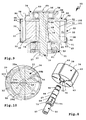
- eine Explosionsdarstellung eines Lamellenmotors der Hand-Werkzeugmaschine gemäß den vorstehenden Figuren,
- Figur 6
- eine perspektivische Schrägansicht des zusammengebauten Lamellenmotors gemäß
Figur 5 , - Figur 7
- einen Rotor des Lamellenmotors,
- Figur 8
- eine Explosionsdarstellung des Rotors sowie eine Motorwelle des Lamellenmotors,
- Figur 9
- einen Querschnitt E-E des Lamellenmotors gemäß
Figur 6 , - Figur 10
- einen Querschnitt entlang einer Linie F-F des Lamellenmotors gemäß
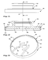
Figur 5 , - Figur 11
- einen oberen Lagerdeckel des Lamellenmotors,
- Figur 12
- einen Querschnitt des Lagerdeckels gemäß
Figur 11 entlang einer Schnittlinie G-G und - Figur 13
- einen unteren Lagerdeckel des Lamellenmotors.
- Eine Hand-Werkzeugmaschine 10 gemäß der Zeichnung bildet eine Schleifmaschine oder Poliermaschine. An einem Gehäuse 11 der Hand-Werkzeugmaschine 10 ist ein Teller-Werkzeug 12 drehbar angeordnet. Das Gehäuse 11 weist einen Handgriffabschnitt 13 sowie einen Motorabschnitt 14 auf. Im Motorabschnitt 14 ist ein Lamellenmotor 15 aufgenommen, der über seine Motorwelle 16 das Teller-Werkzeug 12 antreiben kann.
- Die Hand-Werkzeugmaschine 10 ist eine pneumatische Maschine, das heißt mit Druckluft betreibbar. Diese Druckluft kann über einen Druckluft-Anschluss 17 in das Gehäuse 11 einströmen. Der Druckluft-Anschluss 17 ist hinten am Handgriffabschnitt 13 angeordnet, das heißt, er steht nach hinten vor demselben vor. Dort kann eine Druckluftleitung, zweckmäßigerweise eine Mehrmedienleitung, angeschlossen werden, die nicht nur Druckluft zur Hand-Werkzeugmaschine 10 bringt, sondern auch Abluft und/oder mit Staub beladene Luft von der Hand-Werkzeugmaschine wegfördert. Beispielsweise kann über einen Staubkanal 18, der unterhalb des Handgriffabschnitts 13 verläuft, staubbeladene Luft vom Teller-Werkzeug 12 weggeführt werden.
- Die durch den Druckluft-Anschluss 17 einströmende Druckluft strömt über einen Druckluft-Kanal 19 des Gehäuses 11 ein. Der Druckluft-Kanal 19 führt zu einem Ventil 20, das einen Ventilkörper 21 sowie eine Schließfeder 22 aufweist. Die Schließfeder 22 führt in Richtung einer Schließstellung des Ventils 20, das heißt auf einen Ventilsitz 23. In diese Richtung wirkt auch die aus dem Druckluft-Kanal 19 in Richtung Ventil 20 strömende Druckluft. Die Druckluft wirkt also im Sinne eines Schließens.
- Das Ventil 20 ist in an sich bekannter Weise mittels eines Handgriffs 24 öffenbar. Der Handgriff 24 ist im Bereich des Handgriffabschnitts 13 mit einem Schwenklager 25 schwenkbar gelagert. Ein freies Ende des Handgriffs 24 befindet sich oberhalb des Lamellenmotors 15, das heißt im Bereich einer Handballenauflage oberhalb des Motorabschnitts 14 oder am Motorabschnitt 14.
- Das Betätigungsglied 26 steht nach oben vor das Gehäuse 11 vor und ist mit dem Handgriff 24 bewegungsgekoppelt. Wird dieser nach unten gedrückt, drückt er auch das Betätigungsglied 26 nach unten, so dass das Betätigungsglied 26 den Ventilkörper 21 vom Ventilsitz 23 abhebt. Zwischen dem Betätigungsglied 26 und dem Betätigungsvorsprung 27 ist ein Keilgetriebe oder Schrägflächengetriebe vorhanden.
- Wenn das Ventil 20 geöffnet ist, strömt die Druckluft aus dem Ventil 20 heraus durch einen Kanal 28 hindurch und in einen Drucklufteinlass eines Statorgehäuses 30 des Lamellenmotors 15.
- Die den Lufteinlass 29 durchströmende Druckluft strömt in eine Rotorkammer 31 des Statorgehäuses 30 ein. Die Rotorkammer 31 ist in einem eine Umfangswand 33 aufweisenden Umfangskörper 32 vorgesehen. Der Umfangskörper 32 ist stirnseitig jeweils durch einen oberen Lagerdeckel 34 sowie einen unteren Lagerdeckel 35 verschlossen. In der Rotorkammer 31 ist ein Rotor 36 um eine Drehachse 37 drehbar aufgenommen.
- An einem Rotorköper sind Lamellen 39 beweglich gelagert, nämlich in Lamellenaufnahmen 40 aufgenommen. Die Lamellen 39 sind plattenartig.
- Die Lamellenaufnahmen 40 sind als Schlitze oder Nuten ausgestaltet und sind an einem Außenumfang 41 des Rotorkörpers 38 offen. Somit können also die Lamellen 39, die in den Lamellenaufnahmen 40 quasi stecken, nach radial außen in Richtung eines Innenumfangs der Rotorkammer 31, das heißt zur Umfangswand 33 hin, bewegt werden.
- Der Rotorkörper 38 hat eine zylindrische Gestalt mit einander entgegengesetzten Stirnseiten 42, 43 sowie einem Zylindermantel-Außenumfang 41. Die Lamellenaufnahmen 40 sind zum Außenumfang 41 hin offen. Die Lamellenaufnahmen 40 erstrecken sich von der einen Stirnseite 42 bis zur anderen Stirnseite 43, sind also an den jeweiligen Stirnseiten 42, 43 offen.
- Der Betrieb verläuft nun wie folgt: Der Lufteinlass 29 ist an einem Außenumfang des Umfangskörpers 32 vorgesehen. Vom Lufteinlass 29 strömt die Druckluft über einen Kanal 103 zu einem zum Drehantreiben des Rotors 36 vorgesehenen Einlassbereich 104 und zu einem Einströmkanal 45 am oberen Lagerdeckel 34 und/oder zu einem Einströmkanal 45 am unteren Lagerdeckel 35, über den oder die die Druckluft in Richtung eines Zentrums des Lagerdeckels 34 und/oder Lagerdeckels 35 strömen kann.
- Ein erster Abschnitt 46 des Einströmkanals 45, der als eine Luftzufuhr-Vertiefung am Lagerdeckel 35 ausgestaltet ist, führt also in Richtung Zentrum dieses Lagerdeckels 35. Der Abschnitt 46 ist beispielsweise geradlinig. Jedenfalls ist der Einströmkanal 45 zum Rotorkörper 38, insbesondere den Lamellenaufnahmen 40, zumindest im Bereich eines sich an den Abschnitt 46 anschließenden Verteilabschnitts 47 hin offen. Somit kann den Verteilabschnitt 47 durchströmende Luft in diejenige Lamellenaufnahme 40 strömen, die sich am nächsten beim Lufteinlass 29 befindet. Dadurch wird die in dieser Lamellenaufnahme 40 aufgenommene Lamelle, beispielsweise die Lamelle 39a in der Draufsicht gemäß
Figur 10 , nach radial außen in Richtung der Umfangswand 33 verstellt, so dass sie an dieser mit ihrer flachen Stirnseite im Wesentlichen druckdicht anliegt. - Die Luft strömt von dem Einlassbereich 104, also vom Lufteinlass 29 her, an die jeweils dem Einlassbereich 104 abströmseitig am nächsten gelegene Lamelle 39, z.B. an die Lamelle 39a, so dass der Rotor 36 ein Drehmoment um seine Drehachse 37 erfährt. Die Drehachse 37 ist exzentrisch zu einer Mittelachse 48 der zylindrischen Rotorkammer 31. Dadurch ist es möglich, dass die hinter die Lamelle 39a strömende Luft durch Drehung des Rotors 36 expandiert, was das vorgenannte Drehmoment erzeugt. Beispielsweise steht die Lamelle 39b bereits weiter vor den Außenumfang 41 des Rotorkörpers 38 vor als die Lamelle 39a. Beim Weiterdrehen des Rotors 36 nimmt dieser Raum wieder ab, das heißt, dass beispielsweise die Lamellen 39c, 39d und 39e wieder in Richtung der Drehachse 37 hin verlagert werden, das heißt also tiefer in die Lamellenaufnahmen 40 eindringen. Jedenfalls kann zwischen den Lamellen 39c, 39d und 39e befindliche Luft über einen Ausströmkanal 49 am Lagerdeckel 34 und/oder am Lagerdeckel 35 in Richtung eines Luftausströmauslasses 50 des Statorgehäuses 30 strömen, die Rotorkammer 31 also verlassen.
- Der Luftausströmauslass 50 kommuniziert mit einem Abströmkanal 51 des Gehäuses 11. Der Abströmkanal 51 mündet hinten am Gehäuse 11 im Bereich des Druckluft-Anschlusses 17 aus, kann also mit dem nicht dargestellten Mehrmedienschlauch verbunden werden.
- Der Rotor 36 dreht sehr schnell, das heißt, seine Arbeitsdrehzahl liegt im Bereich zwischen 8000 und 12000 Umdrehungen pro Minute, kann aber auch etwas höher liegen, zum Beispiel 13000 bis 15000 Umdrehungen. Somit ist es also zweckmäßig, wenn der Rotor 36 leicht läuft, das heißt die Reibungsverluste gering sind. Zudem ist es vorteilhaft, wenn auch eine hohe Luft-Dichtigkeit zwischen den oberen und unteren Stirnseiten 42, 43 und den ihnen zugewandten Stirnseiten 52, 53 der Lagerdeckel 34, 35 vorhanden ist. Weiterhin ist es vorteilhaft, wenn die Lamellen 39 leicht in den Lamellenaufnahmen 40 gleiten, so dass dadurch geringe Reibungsverluste entstehen und die Lamellen 39 stets dicht an der Umfangswand 33 anliegen. Es ist also ein verhältnismäßig leichter Rotor 36 mit optimalen Gleiteigenschaften sowohl für den ölfreien Betrieb als auch für den Betrieb mit geölter Druckluft zweckmäßig. Eine hohe Maßgenauigkeit, das heißt eine hohe Präzision der einander zugewandten Flächen der beweglichen Teile (Rotor 36, Lamellen 39) und der statischen Teile (Stirnseiten 52, 53 sowie Umfangswand 33), ist also zweckmäßig. Das alles ist beim Lamellenmotor 15 realisiert, was nachfolgend deutlich wird. Der Rotorkörper 38 besteht zweckmäßigerweise aus einem Elektro-Graphit und/oder einem Kohlenstoffgraphit oder umfasst eine Werkstoffmischung oder Werkstoffkombination, die Elektro-Graphit und/oder Kohlenstoffgraphit enthält. Somit ist er leicht und weist insbesondere im Bereich der Lamellenaufnahmen 40 optimale Gleiteigenschaften auf. Insbesondere tritt wenig Verschleiß im Bereich der Innenflächen 54 der Lamellenaufnahmen 40 und den Lamellen 39 auf. Die jeweiligen Stirnseiten der Lamellen 39 gleiten also an den Innenflächen 54 leichtgängig entlang, so dass ein geringer sogenannter Kolkverschleiß auftritt. Aber auch am Übergangsbereich zwischen den Innenflächen 54 und dem Außenumfang 41, wo Kanten 55 ausgebildet sind, ist allenfalls ein geringer Verschleiß zu beobachten.
- Die Lamellen 39 selbst bestehen zweckmäßigerweise aus einem Feinst-Baumwollgewebelaminat, das mit Phenolharz gebunden ist. Zweckmäßigerweise sind die Lamellen 39 und/oder die Innenflächen der Lamellenaufnahmen 40 mit PTFE beschichtet. Dies senkt die Gleitreibung und damit auch den Verschleiß.
- Die Laufbuchse selbst, das heißt der Umfangskörper 32, besteht zweckmäßigerweise aus Stahl. Besonders bevorzugt ist Chrom-Molybdän-Stahl. Auch die Lagerdeckel 34, 35 bestehen zweckmäßigerweise aus einem Metallwerkstoff, insbesondere dem vorgenannten Stahl. Dieser Materialmix eignet sich ganz besonders gut für den Betrieb des Lamellenmotors 15 sowohl mit geölter als auch mit ungeölter Druckluft. In jedem Fall sind optimale Gleiteigenschaften erzielt.
- Darüber hinaus ist eine hohe Maßgenauigkeit vorhanden, was man insbesondere im Querschnitt gemäß
Figur 9 erkennen kann. - Die Motorwelle 16 steht mit Lagerenden 56, 57 vor die Rotorkammer 31 vor. Die Lagerenden 56, 57 sind mit Drehlagern 58, 59 drehbar gelagert. Die Drehlager 58, 59 sind in Lageraufnahmen 60, 61 an den Lagerdeckeln 34, 35 aufgenommen. Bei den Drehlagern 58, 59 handelt es sich beispielsweise um Kugellager, wobei selbstverständlich auch Nadellader, Pollenlager oder dergleichen ohne weiteres möglich sind. Auch eine Gleitlagerung ist prinzipiell denkbar.
- Die Motorwelle 16 durchdringt Öffnungen 62, 63 an den Lagerdeckeln 34, 35. Das Drehlager 58 stützt sich beispielsweise an einer Stufe der Motorwelle 16 ab, die zwischen dem Lagerende 56 und einem Freiraumabschnitt 64 der Motorwelle 16 vorhanden ist. An der vom Freiraumabschnitt 64 abgewandten Seite ist das Drehlager 58 durch einen Sicherungsring 65 gehalten, der am Lagerende 56 festgelegt ist.
- Der Freiraumabschnitt 64 durchdringt den (oberen) Lagerdeckel 34 im Bereich seiner Öffnung 62.
- Zwischen dem Freiraumabschnitt 64 der Motorwelle 16 und einem Freiraumabschnitt 66 der Wellenaufnahme 44 ist ein gewisser Abstand vorhanden, das heißt, die Motorwelle 16 liegt im Bereich des Zentrierabschnittes 67 normalerweise nicht an der Wellenaufnahme 44 beziehungsweise deren Innenumfang an, hat also ein gewisses Spiel.
- Kein Spiel hingegen ist neben den Freiraumabschnitten 64, 66 vorhanden, nämlich im Bereich eines Zentrierabschnitts 67 der Motorwelle 16, der an einem Zentrierabschnitt 68 der Wellenaufnahme 44 flächig anliegt. Die Zentrierabschnitte 67, 68 sind beispielsweise zylindrisch. Selbstverständlich wären auch andere Geometrien möglich, zum Beispiel dreieckförmige. Allerdings ist es vorteilhaft, dass im Bereich der Zentrierabschnitte 67, 68 keine Drehmitnahme erfolgt, sondern im Bereich von Drehmitnahme-Querschnittskonturen 69, 70 der Motorwelle 16 und der Wellenaufnahme 44.
- Die Drehmitnahme-Querschnittskonturen 69, 70 sind beispielsweise im Querschnitt etwa pentagonal, wobei die Eckbereiche zweckmäßigerweise gerundet sind. Somit liegen also die Flachseiten 71, 72 der Drehmitnahme-Querschnittskonturen 69, 70 im Wesentlichen flächig aneinander an. Zweckmäßig ist es, wenn an den Eckbereichen nur wenig Kraftübertragung erfolgt. Auch im Bereich der Drehmitnahme-Querschnittskonturen 69, 70 ist zweckmäßigerweise ein gewisser Freiraum zwischen der Motorwelle 16 und der Wellenaufnahme 44 vorhanden, so dass die Motorwelle 16 in der Wellenaufnahme 44 ein gewisses Schwenkspiel quer zur Drehachse 37 aufweist. Die Motorwelle 16 ist in gewisser Weise schwimmend in der Wellenaufnahme 44 aufgenommen, was Verspannungen entgegenwirkt. Insbesondere kann die beispielsweise aus Metall, insbesondere Stahl, bestehende Motorwelle 16 den Rotorkörper 38 weniger verspannen, was zu Beschädigungen führen könnte, insbesondere im Hinblick auf das verhältnismäßig spröde Nichtmetall, aus dem der Rotorkörper 38 erfindungsgemäß besteht.
- Die Zentrierabschnitte 67, 68 sind etwa längsmittig (bezogen auf die Drehachse 37) zwischen den Lagerdeckeln 34, 35 angeordnet. Somit ist es möglich, dass die Motorwelle 16 quer zur Drehachse 37 etwas kippen kann, um Zentrierfehler beispielsweise bezüglich der Öffnungen 62, 63, der Drehlager 58, 59 oder dergleichen auszugleichen. Eine gleichmäßige Spannungsverteilung ist somit möglich.
- Es versteht sich, dass eine Motorwelle auch anderweitig am Rotorkörper eines erfindungsgemäßen Motors mit kleiner oder geringer Spannung befestigbar ist. Beispielsweise wäre es möglich, dass die Motorwelle eine ausdehnbare Welle ist, eine Welle mit einem Schlitz, eine Spannwelle oder dergleichen.
- An die Drehmitnahme-Querschnittskontur 69 der Motorwelle 16 schließt sich ein Flansch 73 an, der in der Öffnung 63 des Lagerdeckels 35 angeordnet ist. Zwischen dem Außenumfang des Flansches 73 und der Öffnung 63 ist zweckmäßigerweise eine Dichtung 74 vorgesehen. Es kann aber auch vorgesehen sein, dass im Bereich des Drehlagers 58 oder 59 Luft aus der Rotorkammer 31 ausströmen kann, um das jeweilige Drehlager 58, 59 zu kühlen.
- Am Lagerende 57 der Motorwelle 16 ist ein Lagerkörper 75 angeordnet. Der Lagerkörper 75 ist zweckmäßigerweise auf die Motorwelle 16 aufgepresst, wobei auch ein Schrauben oder dergleichen möglich ist.
- Der Lagerkörper 75 weist eine zur Drehachse 37 exzentrische Lageraufnahme 76 auf, in der ein Drehlager 77 aufgenommen ist. Das Drehlager 77 lagert eine Werkzeugaufnahme 78, an der das Teller-Werkzeug 12 befestigbar ist, zum Beispiel mittels einer Schraube 79. Somit dreht also die Werkzeugaufnahme 78 um eine Exzentrizität 80 bezüglich der Drehachse 37. Die Hand-Werkzeugmaschine 10 bildet also einen Exzentertellerschleifer oder einen Exzentertellerpolierer.
- Damit das Teller-Werkzeug 12 nicht die Drehzahl des Lamellenmotors 15 annimmt, wird es in an sich bekannter Weise gebremst, zum Beispiel durch eine Dichtung 81, die von oben her (stirnseitig) auf das Teller-Werkzeug 12 bremsend einwirkt.
- Beim Betrieb der Hand-Werkzeugmaschine 10 entsteht Wärme. Diese steigt über den Lagerkörper 75 vom (Exzenter-)Drehlager 77 her in Richtung des Rotors 36 auf, so dass sich jedenfalls der Rotorkörper 38 im Verhältnis zum Statorgehäuse 30, insbesondere dem oberen Lagerdeckel 34, stärker erwärmt. Obwohl also ein Wärmeausdehnungskoeffizient des Rotorkörpers 38 etwas geringer ist als derjenige des Umfangskörpers 32, dehnen sich beide Komponenten etwa gleich bezüglich der Drehachse 37 aus, so dass ein Luftspalt zwischen den einander zugewandten Stirnseiten 42, 52 und 43, 53 etwa gleich bleibt, also auch beim Betrieb die geringen Toleranzen zwischen Rotor 36 und Rotorkammer 31 erhalten bleiben. Die Reibung nimmt nicht zu, der Druckluftverbrauch ebenfalls nicht, da die Spaltmaße etwa gleich bleiben.
- Man kann sich vorstellen, dass bei derart geringen Toleranzen eine passgenaue, präzise Fertigung und Montage der Komponenten des Lamellenmotors 15 zweckmäßig ist. Daher sind die Lagerdeckel 34, 35 einem innovativen Konzept folgend am Umfangskörper 32 befestigt.
- Die beiden Lagerkörper haben jeweils Platten 82, deren der Rotorkammer 31 zugewandte Stirnseite 52, 53 als eine Planfläche ausgestaltet ist. Die Platten 82 sind also von ihrem Zentrum (Öffnungen 62, 63) her nach radial außen durchgängig als Planfläche ausgestaltet, so dass die Stirnseiten 52, 53 jedenfalls im Bereich der Rotorkammer 31 plan sind.
- An den von den Stirnseiten 52, 53 abgewandten Seiten sind die Lageraufnahmen 60, 61 angeordnet. Beispielsweise umfassen die Lageraufnahmen 60, 61 jeweils vor diese von der Stirnseite 52, 53 abgewandte Seite vorstehende Ringwände 83, in denen die Drehlager 58, 59 jeweils gehalten sind. An den Ringwänden 83 können Aufnahmen vorgesehen sein, beispielsweise für eine Ringdichtung 84 zwischen der Ringwand 83 und dem Drehlager 58.
- An den Stirnseiten 52, 53 sind also Planflächen 85 vorgesehen, insbesondere auch in einem Anlagebereich 86, mit dem die Stirnseiten 52, 53 an Stirnseiten 87 der Umfangswand 33 jeweils anliegen. Die Stirnseiten 87 sind ringförmig, ebenso die Anlagebereiche 86. Somit kommen die Lagerdeckel 34, 35 stirnseitig plan zur Anlage mit der Umfangswand 33. Fertigungstechnisch ist dies optimal, da nämlich die Stirnseiten 87 und die Planflächen 85 plan und eben bearbeitet werden können. Dennoch ist ein optimaler Halt der Lagerdeckel 34, 35 am Umfangskörper 32 realisiert.
- Die Lagerdeckel 34, 35 werden von Halteeinrichtungen 90 am Umfangskörper 32 zentrierend gehalten. Die Halteeinrichtungen 90 umfassen einen Haltering 91 mit einem ersten Schenkel 92 und einem zweiten Schenkel 93. Der erste Schenkel 92 und der zweite Schenkel 93 sind zueinander rechtwinkelig. Der erste Schenkel 92 hat eine Zentrierfunktion, das heißt, er liegt an einem Außenumfang 88 des Lagerdeckels 34 oder des Lagerdeckels 35 und einem Außenumfang 89 des Rotorkörpers 38 umfangsseitig im Sinne eines Zentrierens an. Im Prinzip würde der erste Schenkel 92 bereits genügen, um diese Zentrierfunktion zu erfüllen.
- Der Außenumfang 88 und der Außenumfang 89 fluchten miteinander.
- Der zweite Schenkel 93 liegt an der von der Rotorkammer 31 abgewandten Stirnseite 94, 95 des Lagerdeckels 34, 35 an und hält somit den jeweiligen Lagerdeckel 34, 35 am Umfangskörper 32.
- Zwischen dem ersten Schenkel 92 und dem Lagerdeckel 34, 35 ist zweckmäßigerweise ein Presssitz vorhanden, während zwischen diesem Schenkel 92 und dem Umfangskörper 32 eine Übergangspassung vorteilhaft ist. Jedenfalls halten die Halteeinrichtungen 90 die beiden Lagerdeckel 34, 35 am Umfangskörper 32, so dass der Lamellenmotor 15 als Ganzes in eine Motoraufnahme 96 des Gehäuses 11 eingesetzt werden kann. Ein Haltering 97, in dessen Innenumfang beispielsweise das Drehlager 59 vorsteht, hält den Lamellenmotor 15 in der Motoraufnahme 96. Ein Passstift 98 steht vor das Statorgehäuse 30 vor und ist in einer Aufnahme 99 im Bereich der Motoraufnahme 96 aufgenommen, so dass der Lamellenmotor 15 drehwinkelrichtig in der Motoraufnahme 96 montierbar ist, so dass der Lufteinlass 29 mit dem Kanal 28 kommunizieren kann.
- Der Passstift 98 ist in den Umfangskörper 32 eingesetzt, zweckmäßigerweise eingepresst und/oder ohne Spiel im Umfangskörper 32 aufgenommen, und durchdringt den Lagerdeckel 34 und/oder 35, der hierfür eine Bohrung oder einen Durchgang 105 hat. Ein Innenquerschnitt des Durchgangs 105 ist größer als ein Außenquerschnitt des Passstifts 98, der also mit Spiel im Durchgang 105 aufgenommen ist. Daher können die Halteeinrichtungen 90 den Lagerdeckel 34 und/oder 35 am Umfangskörper 32 zentrierend halten.
- Der Passstift 98 bildet eine Verdrehsicherung für den Lagerdeckel 34 und/oder 35 gegenüber dem Umfangskörper 32. Zweckmäßigerweise ist vorgesehen, dass diese Verdrehsicherung nicht mehr erforderlich ist, wenn der Haltering 97 den Lamellenmotor 15 in der Motoraufnahme 96 hält, insbesondere verspannt.
- Zur Aufnahme des 2. Schenkels 93 ist an den Stirnseiten 94, 95 der Lagerdeckel 34, 35 jeweils eine Stufe 100 vorhanden. Somit steht der Schenkel 93 nicht oder nur unwesentlich vor die obere bzw. untere Stirnseite 94, 95 des Lagerdeckels 34, 35 vor. Zwischen einem mittleren Außenumfang 101 des Umfangskörpers 32 und dem jeweiligen Außenumfang 89 ist eine weitere Stufe 102 für den Schenkel 92 vorgesehen.
Claims (15)
- Hand-Werkzeugmaschine, insbesondere Schleifgerät, Poliergerät oder Schraubgerät, mit einem pneumatischer Lamellenmotor (15), wobei der Lamellenmotor (15) ein Statorgehäuse (30) aufweist, das eine Rotorkammer (31) aufweist, in der ein mit einer Motorwelle (16) versehener Rotor (36) drehbar aufgenommen ist, wobei der Rotor (36) einen Rotorkörper (38) und an Lamellenaufnahmen (40) des Rotorkörpers (38) zu einer Umfangswand (33) der Rotorkammer (31) hin beweglich gelagerte Lamellen (39) aufweist, und wobei das Statorgehäuse (30) einen die Umfangswand (33) aufweisenden Umfangskörper (32) sowie mindestens einen von dem Umfangskörper (32) separaten und die Rotorkammer (31) stirnseitig verschließenden Lagerdeckel (34, 35) umfasst, wobei die Motorwelle (16) mit einem Längsende vor die Rotorkammer (31) vorsteht und an dem mindestens einen Lagerdeckel (34, 35) um eine Drehachse (37) drehbar gelagert ist, wobei der mindestens eine Lagerdeckel (34, 35) mit einer der Rotorkammer (31) zugewandten Stirnseite (52, 53) auf einer dem mindestens einen Lagerdeckel (34, 35) zugewandten Stirnseite (87) der Umfangswand (33) aufliegt, dadurch gekennzeichnet, dass der mindestens eine Lagerdeckel (34, 35) relativ zumUmfangskörper (32) bezüglich der Drehachse (37) der Motorwelle (16) durch eine von dem mindestens einen Lagerdeckel (34, 35) und dem Umfangskörper (32) separate Halteeinrichtung (90) zentriert ist, die an mindestens zwei bezogen auf die Drehachse (37) zueinander drehwinkelversetzten Seiten in Richtung der Drehachse (37) wirkend an dem Lagerdeckel (34, 35) und der Umfangswand (33) anliegt.
- Hand-Werkzeugmaschine nach Anspruch 1, dadurch gekennzeichnet, dass die Halteeinrichtung (90) eine Hülse oder einen Ring umfasst, der am Außenumfang (88, 89) des mindestens einen Lagerdeckels (34, 35) und des Umfangskörpers (32) anliegt.
- Hand-Werkzeugmaschine nach Anspruch 1 oder 2, dadurch gekennzeichnet, dass die Halteeinrichtung (90) einen ersten, am Außenumfang des mindestens einen Lagerdeckels (34, 35) und des Umfangskörpers (32) anliegenden Schenkel (92) und einen zweiten Schenkel (93) aufweist und, der sich an einer von dem Umfangskörper (32) abgewandten Stirnseite (94, 95) des mindestens einen Lagerdeckels (34, 35) abstützt und diesen zum Umfangskörper (32) hin kraftbeaufschlagt.
- Hand-Werkzeugmaschine nach Anspruch 3, dadurch gekennzeichnet, dass der erste Schenkel (92) und der zweite Schenkel (93) zueinander rechtwinkelig sind.
- Hand-Werkzeugmaschine nach einem der vorhergehenden Ansprüche, dadurch gekennzeichnet, dass die Halteeinrichtung (90) mit einem Presssitz an dem mindestens einen Lagerdeckel (34, 35) befestigt ist.
- Hand-Werkzeugmaschine nach einem der vorhergehenden Ansprüche, dadurch gekennzeichnet, dass die Halteeinrichtung (90) mit einer Übergangspassung am Umfangskörper (32) anliegt.
- Hand-Werkzeugmaschine nach einem der vorhergehenden Ansprüche, dadurch gekennzeichnet, dass die Stirnseite (87) der Umfangswand (33) und/oder eine der Umfangswand (33) zugewandte stirnseitige Ringfläche des mindestens einen Lagerdeckels (34, 35) Planflächen (85) sind.
- Hand-Werkzeugmaschine nach einem der vorhergehenden Ansprüche, dadurch gekennzeichnet, dass der mindestens eine Lagerdeckel (34, 35) eine sich über seine gesamte, der Rotorkammer (31) zugewandte Stirnseite (52, 53) erstreckende im Wesentlichen plane oder vollständig plane Stirnseitenfläche aufweist.
- Hand-Werkzeugmaschine nach einem der vorhergehenden Ansprüche, dadurch gekennzeichnet, dass an der der Rotorkammer (31) zugewandten Stirnseite (52, 53) des mindestens einen Lagerdeckels (34, 35) mindestens eine Luftzufuhr-Vertiefung angeordnet ist, die zu einem von der Drehachse (37) durchsetzten Zentrum des mindestens einen Lagerdeckels (34, 35) derart verläuft, dass Luft zumindest hinter diejenige Lamelle (39) strömen kann, die sich jeweils am nächsten bei einem Lufteinlass (29) des Motors befindet.
- Hand-Werkzeugmaschine nach einem der vorhergehenden Ansprüche, dadurch gekennzeichnet, dass an dem mindestens einen Lagerdeckel (34, 35) ein Luftausströmauslass (50) angeordnet ist, durch den Luft aus der Rotorkammer (31) zu einem an dem Lagerdeckel (34, 35) angeordneten Lager strömen kann.
- Hand-Werkzeugmaschine nach einem der vorhergehenden Ansprüche, dadurch gekennzeichnet, dass ein Lagerkörper (75) von einem an dem mindestens einen Lagerdeckel (34, 35) angeordneten Drehlager (59) drehbar aufgenommen ist, wobei der Lagerkörper (75) eine zur Drehachse (37) des Motors exzentrische Lageraufnahme (76) aufweist, in der ein Drehlager zum drehbaren Lagern einer Werkzeugaufnahme angeordnet ist.
- Hand-Werkzeugmaschine nach einem der vorhergehenden Ansprüche, dadurch gekennzeichnet, dass mindestens eine der Lamellen (39) und/oder das Statorgehäuse (30) und/oder der Rotorkörper (38) zumindest teilweise aus einem nicht-metallischen Werkstoff besteht, wobei der nicht-metallische Werkstoff einen Graphit-Werkstoff und/oder einen Keramik-Werkstoff umfasst oder bildet.
- Hand-Werkzeugmaschine nach einem der vorhergehenden Ansprüche, dadurch gekennzeichnet, dass die Halteeinrichtung (90) das einzige Haltemittel zum Halten des mindestens einen Lagerdeckels (34, 35) an dem Umfangskörper (32) bezüglich Kräften quer zu der Drehachse (37) der Motorwelle (16) bildet und/oder dass eine gegen eine Relativverdrehung des mindestens einen Lagerdeckels (34, 35) gegenüber dem Umfangskörper (32) ein Spiel quer zur Drehachse (37) der Motorwelle (16) an dem mindestens einen Lagerdeckel (34, 35) und/oder dem Umfangskörper (32) aufweist.
- Hand-Werkzeugmaschine nach einem der vorhergehenden Ansprüche, dadurch gekennzeichnet, dass die Halteeinrichtung (90) das einzige Haltemittel zum Halten des mindestens einen Lagerdeckels (34, 35) an dem Umfangskörper (32), insbesondere quer zu der Drehachse (37) der Motorwelle (16), bildet und/oder dass keine sich parallel und/oder quer zu der Drehachse (37) der Motorwelle (16) erstreckende Bolzen oder Stifte oder Haltevorsprünge vorgesehen sind.
- Pneumatischer Lamellenmotor (15), für eine Hand-Werkzeugmaschine, insbesondere ein Schleifgerät, Poliergerät oder Schraubgerät, wobei der Lamellenmotor (15) ein Statorgehäuse (30) aufweist, das eine Rotorkammer (31) aufweist, in der ein mit einer Motorwelle (16) versehener Rotor (36) drehbar aufgenommen ist, wobei der Rotor (36) einen Rotorkörper (38) und an Lamellenaufnahmen (40) des Rotorkörpers (38) zu einer Umfangswand (33) der Rotorkammer (31) hin beweglich gelagerte Lamellen (39) aufweist, und wobei das Statorgehäuse (30) einen die Umfangswand (33) aufweisenden Umfangskörper (32) sowie mindestens einen von dem Umfangskörper (32) separaten und die Rotorkammer (31) stirnseitig verschließenden Lagerdeckel (34, 35) umfasst, wobei die Motorwelle (16) mit einem Längsende vor die Rotorkammer (31) vorsteht und an dem mindestens einen Lagerdeckel (34, 35) um eine Drehachse (37) drehbar gelagert ist, wobei der mindestens eine Lagerdeckel (34, 35) mit einer der Rotorkammer (31) zugewandten Stirnseite (52, 53) auf einer dem mindestens einen Lagerdeckel (34, 35) zugewandten Stirnseite (87) der Umfangswand (33) aufliegt, dadurch gekennzeichnet, dass der mindestens eine Lagerdeckel (34, 35) relativ zum Umfangskörper (32) bezüglich der Drehachse (37) der Motorwelle (16) durch eine von dem mindestens einen Lagerdeckel (34, 35) und dem Umfangskörper (32) separate Halteeinrichtung (90) zentriert ist, die an mindestens zwei bezogen auf die Drehachse (37) zueinander drehwinkelversetzten Seiten in Richtung der Drehachse (37) wirkend an dem Lagerdeckel (34, 35) und der Umfangswand (33) anliegt.
Applications Claiming Priority (1)
| Application Number | Priority Date | Filing Date | Title |
|---|---|---|---|
| DE102011011382A DE102011011382A1 (de) | 2011-02-17 | 2011-02-17 | Hand-Werkzeugmaschine mit einem Lamellenmotor und einem Lagerdeckel |
Publications (3)
| Publication Number | Publication Date |
|---|---|
| EP2489832A2 true EP2489832A2 (de) | 2012-08-22 |
| EP2489832A3 EP2489832A3 (de) | 2016-11-23 |
| EP2489832B1 EP2489832B1 (de) | 2019-04-24 |
Family
ID=45495584
Family Applications (1)
| Application Number | Title | Priority Date | Filing Date |
|---|---|---|---|
| EP11010206.8A Not-in-force EP2489832B1 (de) | 2011-02-17 | 2011-12-24 | Pneumatischer lamellenmotor für eine hand-werkzeugmachine |
Country Status (2)
| Country | Link |
|---|---|
| EP (1) | EP2489832B1 (de) |
| DE (1) | DE102011011382A1 (de) |
Citations (2)
| Publication number | Priority date | Publication date | Assignee | Title |
|---|---|---|---|---|
| DE3939096A1 (de) | 1989-11-25 | 1991-05-29 | Klaus Union Armaturen | Lamellenlaeufer zur verwendung als motor oder pumpe |
| DE10259096B4 (de) | 2002-01-26 | 2004-10-07 | Deprag Schulz Gmbh U. Co | Druckluft-Lamellenmotor |
Family Cites Families (6)
| Publication number | Priority date | Publication date | Assignee | Title |
|---|---|---|---|---|
| US2159232A (en) * | 1937-10-28 | 1939-05-23 | William H Keller Inc | Pressure fluid motor |
| IT1141570B (it) * | 1980-04-11 | 1986-10-01 | Leonardo Beltrame | Perfezionamento ai corpi dei compressori rotativi,e metodo per la realizzazione di essi |
| DE4103149A1 (de) * | 1991-02-02 | 1992-08-06 | Behrendt Burkhard Dipl Ing Tu | Mittels druckluft arbeitender lamellenmotor |
| US6066033A (en) * | 1998-07-29 | 2000-05-23 | K-R Industry Company Limited | Rotational speed adjusting device for a pneumatic rotational tool |
| US20090084259A1 (en) * | 2007-09-27 | 2009-04-02 | Li-Chen Chen | Pneumatic Tool |
| US20090255399A1 (en) * | 2008-04-15 | 2009-10-15 | Pei-Chin Hung | Pneumatic motor |
-
2011
- 2011-02-17 DE DE102011011382A patent/DE102011011382A1/de not_active Withdrawn
- 2011-12-24 EP EP11010206.8A patent/EP2489832B1/de not_active Not-in-force
Patent Citations (2)
| Publication number | Priority date | Publication date | Assignee | Title |
|---|---|---|---|---|
| DE3939096A1 (de) | 1989-11-25 | 1991-05-29 | Klaus Union Armaturen | Lamellenlaeufer zur verwendung als motor oder pumpe |
| DE10259096B4 (de) | 2002-01-26 | 2004-10-07 | Deprag Schulz Gmbh U. Co | Druckluft-Lamellenmotor |
Also Published As
| Publication number | Publication date |
|---|---|
| EP2489832A3 (de) | 2016-11-23 |
| EP2489832B1 (de) | 2019-04-24 |
| DE102011011382A1 (de) | 2012-08-23 |
Similar Documents
| Publication | Publication Date | Title |
|---|---|---|
| EP2137378B1 (de) | Pumpe oder motor | |
| DE102011011384B4 (de) | Hand-Werkzeugmaschine mit einem Lamellenmotor aus einem Nicht-Metall | |
| DE102013226445B4 (de) | Nockenwellenzentrierung im geteilten Rotor eines hydraulischen Nockenwellenverstellers und zugehöriges Herstellungsverfahren | |
| EP2364813A2 (de) | Honwerkzeug | |
| DE3913908A1 (de) | Druckluftlamellenmotor | |
| EP2997273A1 (de) | Radialgleitlager | |
| WO2005028901A1 (de) | Hilfsaggregatantrieb für einen fahrzeugmotor mit zu- und entkoppelbarer riemenscheibe sowie hilfsaggregat | |
| EP2489832B1 (de) | Pneumatischer lamellenmotor für eine hand-werkzeugmachine | |
| DE3046335A1 (de) | Rotationskompressor | |
| DE102010014393A1 (de) | Tragbares Motorwerkzeug mit einer Unwuchtausgleichsvorrichtung und einer Spannvorrichtung für ein rotationssymmetrisches Arbeitsmittel | |
| DE102010012023B4 (de) | Hand-Werkzeugmaschine mit einem Teller-Werkzeug | |
| WO2003036094A2 (de) | Vakuumpumpe | |
| DE102010064130A1 (de) | Axialscheibe und Zahnradpumpe mit Axialscheibe | |
| DE19834033A1 (de) | Vakuumpumpe | |
| WO2011023393A1 (de) | Reibschaltkupplung zur betätigung mit einem strömungsfähigen druckmittel | |
| EP4217610B1 (de) | Motor-pumpe-einheit | |
| WO1996015368A1 (de) | Dichtungsanordnung an einer kolben-zylinder-einheit | |
| EP2112395A1 (de) | Brems- und/oder Klemmvorrichtung für Wellen | |
| EP1637771A2 (de) | Gewindetrieb | |
| EP3249156B1 (de) | Maschine, insbesondere ölförderpumpe | |
| EP1216372A1 (de) | Wellenabdichtung, insbesondere für axialkolbenverdichter | |
| EP0381682B1 (de) | Drehkolbenverdichter | |
| DE102012217392A1 (de) | Nockenwellenversteller | |
| DE9209641U1 (de) | Wälzkolbenpumpe | |
| DE10028336C1 (de) | Axialkolbenmaschine |
Legal Events
| Date | Code | Title | Description |
|---|---|---|---|
| PUAI | Public reference made under article 153(3) epc to a published international application that has entered the european phase |
Free format text: ORIGINAL CODE: 0009012 |
|
| AK | Designated contracting states |
Kind code of ref document: A2 Designated state(s): AL AT BE BG CH CY CZ DE DK EE ES FI FR GB GR HR HU IE IS IT LI LT LU LV MC MK MT NL NO PL PT RO RS SE SI SK SM TR |
|
| AX | Request for extension of the european patent |
Extension state: BA ME |
|
| RAP1 | Party data changed (applicant data changed or rights of an application transferred) |
Owner name: FESTOOL GROUP GMBH & CO. KG |
|
| RAP1 | Party data changed (applicant data changed or rights of an application transferred) |
Owner name: FESTOOL GMBH |
|
| PUAL | Search report despatched |
Free format text: ORIGINAL CODE: 0009013 |
|
| AK | Designated contracting states |
Kind code of ref document: A3 Designated state(s): AL AT BE BG CH CY CZ DE DK EE ES FI FR GB GR HR HU IE IS IT LI LT LU LV MC MK MT NL NO PL PT RO RS SE SI SK SM TR |
|
| AX | Request for extension of the european patent |
Extension state: BA ME |
|
| RIC1 | Information provided on ipc code assigned before grant |
Ipc: F01C 1/344 20060101ALI20161020BHEP Ipc: F01C 21/10 20060101ALI20161020BHEP Ipc: F01C 1/10 20060101AFI20161020BHEP |
|
| STAA | Information on the status of an ep patent application or granted ep patent |
Free format text: STATUS: REQUEST FOR EXAMINATION WAS MADE |
|
| 17P | Request for examination filed |
Effective date: 20170420 |
|
| RBV | Designated contracting states (corrected) |
Designated state(s): AL AT BE BG CH CY CZ DE DK EE ES FI FR GB GR HR HU IE IS IT LI LT LU LV MC MK MT NL NO PL PT RO RS SE SI SK SM TR |
|
| GRAP | Despatch of communication of intention to grant a patent |
Free format text: ORIGINAL CODE: EPIDOSNIGR1 |
|
| STAA | Information on the status of an ep patent application or granted ep patent |
Free format text: STATUS: GRANT OF PATENT IS INTENDED |
|
| INTG | Intention to grant announced |
Effective date: 20181221 |
|
| GRAS | Grant fee paid |
Free format text: ORIGINAL CODE: EPIDOSNIGR3 |
|
| GRAA | (expected) grant |
Free format text: ORIGINAL CODE: 0009210 |
|
| STAA | Information on the status of an ep patent application or granted ep patent |
Free format text: STATUS: THE PATENT HAS BEEN GRANTED |
|
| AK | Designated contracting states |
Kind code of ref document: B1 Designated state(s): AL AT BE BG CH CY CZ DE DK EE ES FI FR GB GR HR HU IE IS IT LI LT LU LV MC MK MT NL NO PL PT RO RS SE SI SK SM TR |
|
| REG | Reference to a national code |
Ref country code: GB Ref legal event code: FG4D Free format text: NOT ENGLISH |
|
| REG | Reference to a national code |
Ref country code: CH Ref legal event code: EP |
|
| REG | Reference to a national code |
Ref country code: DE Ref legal event code: R096 Ref document number: 502011015617 Country of ref document: DE |
|
| REG | Reference to a national code |
Ref country code: AT Ref legal event code: REF Ref document number: 1124402 Country of ref document: AT Kind code of ref document: T Effective date: 20190515 Ref country code: IE Ref legal event code: FG4D Free format text: LANGUAGE OF EP DOCUMENT: GERMAN |
|
| REG | Reference to a national code |
Ref country code: NL Ref legal event code: FP |
|
| REG | Reference to a national code |
Ref country code: LT Ref legal event code: MG4D |
|
| PG25 | Lapsed in a contracting state [announced via postgrant information from national office to epo] |
Ref country code: AL Free format text: LAPSE BECAUSE OF FAILURE TO SUBMIT A TRANSLATION OF THE DESCRIPTION OR TO PAY THE FEE WITHIN THE PRESCRIBED TIME-LIMIT Effective date: 20190424 Ref country code: PT Free format text: LAPSE BECAUSE OF FAILURE TO SUBMIT A TRANSLATION OF THE DESCRIPTION OR TO PAY THE FEE WITHIN THE PRESCRIBED TIME-LIMIT Effective date: 20190824 Ref country code: SE Free format text: LAPSE BECAUSE OF FAILURE TO SUBMIT A TRANSLATION OF THE DESCRIPTION OR TO PAY THE FEE WITHIN THE PRESCRIBED TIME-LIMIT Effective date: 20190424 Ref country code: FI Free format text: LAPSE BECAUSE OF FAILURE TO SUBMIT A TRANSLATION OF THE DESCRIPTION OR TO PAY THE FEE WITHIN THE PRESCRIBED TIME-LIMIT Effective date: 20190424 Ref country code: HR Free format text: LAPSE BECAUSE OF FAILURE TO SUBMIT A TRANSLATION OF THE DESCRIPTION OR TO PAY THE FEE WITHIN THE PRESCRIBED TIME-LIMIT Effective date: 20190424 Ref country code: NO Free format text: LAPSE BECAUSE OF FAILURE TO SUBMIT A TRANSLATION OF THE DESCRIPTION OR TO PAY THE FEE WITHIN THE PRESCRIBED TIME-LIMIT Effective date: 20190724 Ref country code: ES Free format text: LAPSE BECAUSE OF FAILURE TO SUBMIT A TRANSLATION OF THE DESCRIPTION OR TO PAY THE FEE WITHIN THE PRESCRIBED TIME-LIMIT Effective date: 20190424 Ref country code: LT Free format text: LAPSE BECAUSE OF FAILURE TO SUBMIT A TRANSLATION OF THE DESCRIPTION OR TO PAY THE FEE WITHIN THE PRESCRIBED TIME-LIMIT Effective date: 20190424 |
|
| PG25 | Lapsed in a contracting state [announced via postgrant information from national office to epo] |
Ref country code: PL Free format text: LAPSE BECAUSE OF FAILURE TO SUBMIT A TRANSLATION OF THE DESCRIPTION OR TO PAY THE FEE WITHIN THE PRESCRIBED TIME-LIMIT Effective date: 20190424 Ref country code: RS Free format text: LAPSE BECAUSE OF FAILURE TO SUBMIT A TRANSLATION OF THE DESCRIPTION OR TO PAY THE FEE WITHIN THE PRESCRIBED TIME-LIMIT Effective date: 20190424 Ref country code: BG Free format text: LAPSE BECAUSE OF FAILURE TO SUBMIT A TRANSLATION OF THE DESCRIPTION OR TO PAY THE FEE WITHIN THE PRESCRIBED TIME-LIMIT Effective date: 20190724 Ref country code: GR Free format text: LAPSE BECAUSE OF FAILURE TO SUBMIT A TRANSLATION OF THE DESCRIPTION OR TO PAY THE FEE WITHIN THE PRESCRIBED TIME-LIMIT Effective date: 20190725 Ref country code: LV Free format text: LAPSE BECAUSE OF FAILURE TO SUBMIT A TRANSLATION OF THE DESCRIPTION OR TO PAY THE FEE WITHIN THE PRESCRIBED TIME-LIMIT Effective date: 20190424 |
|
| PG25 | Lapsed in a contracting state [announced via postgrant information from national office to epo] |
Ref country code: IS Free format text: LAPSE BECAUSE OF FAILURE TO SUBMIT A TRANSLATION OF THE DESCRIPTION OR TO PAY THE FEE WITHIN THE PRESCRIBED TIME-LIMIT Effective date: 20190824 |
|
| REG | Reference to a national code |
Ref country code: DE Ref legal event code: R097 Ref document number: 502011015617 Country of ref document: DE |
|
| PG25 | Lapsed in a contracting state [announced via postgrant information from national office to epo] |
Ref country code: DK Free format text: LAPSE BECAUSE OF FAILURE TO SUBMIT A TRANSLATION OF THE DESCRIPTION OR TO PAY THE FEE WITHIN THE PRESCRIBED TIME-LIMIT Effective date: 20190424 Ref country code: CZ Free format text: LAPSE BECAUSE OF FAILURE TO SUBMIT A TRANSLATION OF THE DESCRIPTION OR TO PAY THE FEE WITHIN THE PRESCRIBED TIME-LIMIT Effective date: 20190424 Ref country code: EE Free format text: LAPSE BECAUSE OF FAILURE TO SUBMIT A TRANSLATION OF THE DESCRIPTION OR TO PAY THE FEE WITHIN THE PRESCRIBED TIME-LIMIT Effective date: 20190424 Ref country code: SK Free format text: LAPSE BECAUSE OF FAILURE TO SUBMIT A TRANSLATION OF THE DESCRIPTION OR TO PAY THE FEE WITHIN THE PRESCRIBED TIME-LIMIT Effective date: 20190424 Ref country code: RO Free format text: LAPSE BECAUSE OF FAILURE TO SUBMIT A TRANSLATION OF THE DESCRIPTION OR TO PAY THE FEE WITHIN THE PRESCRIBED TIME-LIMIT Effective date: 20190424 |
|
| PG25 | Lapsed in a contracting state [announced via postgrant information from national office to epo] |
Ref country code: SM Free format text: LAPSE BECAUSE OF FAILURE TO SUBMIT A TRANSLATION OF THE DESCRIPTION OR TO PAY THE FEE WITHIN THE PRESCRIBED TIME-LIMIT Effective date: 20190424 |
|
| PLBE | No opposition filed within time limit |
Free format text: ORIGINAL CODE: 0009261 |
|
| STAA | Information on the status of an ep patent application or granted ep patent |
Free format text: STATUS: NO OPPOSITION FILED WITHIN TIME LIMIT |
|
| PG25 | Lapsed in a contracting state [announced via postgrant information from national office to epo] |
Ref country code: TR Free format text: LAPSE BECAUSE OF FAILURE TO SUBMIT A TRANSLATION OF THE DESCRIPTION OR TO PAY THE FEE WITHIN THE PRESCRIBED TIME-LIMIT Effective date: 20190424 |
|
| 26N | No opposition filed |
Effective date: 20200127 |
|
| PG25 | Lapsed in a contracting state [announced via postgrant information from national office to epo] |
Ref country code: SI Free format text: LAPSE BECAUSE OF FAILURE TO SUBMIT A TRANSLATION OF THE DESCRIPTION OR TO PAY THE FEE WITHIN THE PRESCRIBED TIME-LIMIT Effective date: 20190424 |
|
| REG | Reference to a national code |
Ref country code: CH Ref legal event code: PL |
|
| REG | Reference to a national code |
Ref country code: BE Ref legal event code: MM Effective date: 20191231 |
|
| PG25 | Lapsed in a contracting state [announced via postgrant information from national office to epo] |
Ref country code: MC Free format text: LAPSE BECAUSE OF FAILURE TO SUBMIT A TRANSLATION OF THE DESCRIPTION OR TO PAY THE FEE WITHIN THE PRESCRIBED TIME-LIMIT Effective date: 20190424 |
|
| PG25 | Lapsed in a contracting state [announced via postgrant information from national office to epo] |
Ref country code: IE Free format text: LAPSE BECAUSE OF NON-PAYMENT OF DUE FEES Effective date: 20191224 Ref country code: LU Free format text: LAPSE BECAUSE OF NON-PAYMENT OF DUE FEES Effective date: 20191224 |
|
| PG25 | Lapsed in a contracting state [announced via postgrant information from national office to epo] |
Ref country code: LI Free format text: LAPSE BECAUSE OF NON-PAYMENT OF DUE FEES Effective date: 20191231 Ref country code: CH Free format text: LAPSE BECAUSE OF NON-PAYMENT OF DUE FEES Effective date: 20191231 Ref country code: BE Free format text: LAPSE BECAUSE OF NON-PAYMENT OF DUE FEES Effective date: 20191231 |
|
| REG | Reference to a national code |
Ref country code: AT Ref legal event code: MM01 Ref document number: 1124402 Country of ref document: AT Kind code of ref document: T Effective date: 20191224 |
|
| PG25 | Lapsed in a contracting state [announced via postgrant information from national office to epo] |
Ref country code: CY Free format text: LAPSE BECAUSE OF FAILURE TO SUBMIT A TRANSLATION OF THE DESCRIPTION OR TO PAY THE FEE WITHIN THE PRESCRIBED TIME-LIMIT Effective date: 20190424 Ref country code: AT Free format text: LAPSE BECAUSE OF NON-PAYMENT OF DUE FEES Effective date: 20191224 |
|
| PG25 | Lapsed in a contracting state [announced via postgrant information from national office to epo] |
Ref country code: MT Free format text: LAPSE BECAUSE OF FAILURE TO SUBMIT A TRANSLATION OF THE DESCRIPTION OR TO PAY THE FEE WITHIN THE PRESCRIBED TIME-LIMIT Effective date: 20190424 Ref country code: HU Free format text: LAPSE BECAUSE OF FAILURE TO SUBMIT A TRANSLATION OF THE DESCRIPTION OR TO PAY THE FEE WITHIN THE PRESCRIBED TIME-LIMIT; INVALID AB INITIO Effective date: 20111224 |
|
| PG25 | Lapsed in a contracting state [announced via postgrant information from national office to epo] |
Ref country code: MK Free format text: LAPSE BECAUSE OF FAILURE TO SUBMIT A TRANSLATION OF THE DESCRIPTION OR TO PAY THE FEE WITHIN THE PRESCRIBED TIME-LIMIT Effective date: 20190424 |
|
| PGFP | Annual fee paid to national office [announced via postgrant information from national office to epo] |
Ref country code: NL Payment date: 20221222 Year of fee payment: 12 Ref country code: IT Payment date: 20221108 Year of fee payment: 12 Ref country code: GB Payment date: 20221108 Year of fee payment: 12 Ref country code: FR Payment date: 20221110 Year of fee payment: 12 Ref country code: DE Payment date: 20221111 Year of fee payment: 12 |
|
| P01 | Opt-out of the competence of the unified patent court (upc) registered |
Effective date: 20230517 |
|
| REG | Reference to a national code |
Ref country code: DE Ref legal event code: R119 Ref document number: 502011015617 Country of ref document: DE |
|
| REG | Reference to a national code |
Ref country code: NL Ref legal event code: MM Effective date: 20240101 |
|
| GBPC | Gb: european patent ceased through non-payment of renewal fee |
Effective date: 20231224 |
|
| PG25 | Lapsed in a contracting state [announced via postgrant information from national office to epo] |
Ref country code: NL Free format text: LAPSE BECAUSE OF NON-PAYMENT OF DUE FEES Effective date: 20240101 |
|
| PG25 | Lapsed in a contracting state [announced via postgrant information from national office to epo] |
Ref country code: NL Free format text: LAPSE BECAUSE OF NON-PAYMENT OF DUE FEES Effective date: 20240101 |
|
| PG25 | Lapsed in a contracting state [announced via postgrant information from national office to epo] |
Ref country code: DE Free format text: LAPSE BECAUSE OF NON-PAYMENT OF DUE FEES Effective date: 20240702 |
|
| PG25 | Lapsed in a contracting state [announced via postgrant information from national office to epo] |
Ref country code: GB Free format text: LAPSE BECAUSE OF NON-PAYMENT OF DUE FEES Effective date: 20231224 |
|
| PG25 | Lapsed in a contracting state [announced via postgrant information from national office to epo] |
Ref country code: FR Free format text: LAPSE BECAUSE OF NON-PAYMENT OF DUE FEES Effective date: 20231231 |
|
| PG25 | Lapsed in a contracting state [announced via postgrant information from national office to epo] |
Ref country code: GB Free format text: LAPSE BECAUSE OF NON-PAYMENT OF DUE FEES Effective date: 20231224 Ref country code: FR Free format text: LAPSE BECAUSE OF NON-PAYMENT OF DUE FEES Effective date: 20231231 Ref country code: DE Free format text: LAPSE BECAUSE OF NON-PAYMENT OF DUE FEES Effective date: 20240702 |
|
| PG25 | Lapsed in a contracting state [announced via postgrant information from national office to epo] |
Ref country code: IT Free format text: LAPSE BECAUSE OF NON-PAYMENT OF DUE FEES Effective date: 20231224 |