EP2489759B1 - System for utilization improvement of process chambers and method of operating thereof - Google Patents
System for utilization improvement of process chambers and method of operating thereof Download PDFInfo
- Publication number
- EP2489759B1 EP2489759B1 EP11155238.6A EP11155238A EP2489759B1 EP 2489759 B1 EP2489759 B1 EP 2489759B1 EP 11155238 A EP11155238 A EP 11155238A EP 2489759 B1 EP2489759 B1 EP 2489759B1
- Authority
- EP
- European Patent Office
- Prior art keywords
- chamber
- processing
- layer
- transportation
- transportation track
- Prior art date
- Legal status (The legal status is an assumption and is not a legal conclusion. Google has not performed a legal analysis and makes no representation as to the accuracy of the status listed.)
- Not-in-force
Links
Images


Classifications
-
- C—CHEMISTRY; METALLURGY
- C23—COATING METALLIC MATERIAL; COATING MATERIAL WITH METALLIC MATERIAL; CHEMICAL SURFACE TREATMENT; DIFFUSION TREATMENT OF METALLIC MATERIAL; COATING BY VACUUM EVAPORATION, BY SPUTTERING, BY ION IMPLANTATION OR BY CHEMICAL VAPOUR DEPOSITION, IN GENERAL; INHIBITING CORROSION OF METALLIC MATERIAL OR INCRUSTATION IN GENERAL
- C23C—COATING METALLIC MATERIAL; COATING MATERIAL WITH METALLIC MATERIAL; SURFACE TREATMENT OF METALLIC MATERIAL BY DIFFUSION INTO THE SURFACE, BY CHEMICAL CONVERSION OR SUBSTITUTION; COATING BY VACUUM EVAPORATION, BY SPUTTERING, BY ION IMPLANTATION OR BY CHEMICAL VAPOUR DEPOSITION, IN GENERAL
- C23C14/00—Coating by vacuum evaporation, by sputtering or by ion implantation of the coating forming material
- C23C14/22—Coating by vacuum evaporation, by sputtering or by ion implantation of the coating forming material characterised by the process of coating
- C23C14/56—Apparatus specially adapted for continuous coating; Arrangements for maintaining the vacuum, e.g. vacuum locks
- C23C14/568—Transferring the substrates through a series of coating stations
-
- B—PERFORMING OPERATIONS; TRANSPORTING
- B05—SPRAYING OR ATOMISING IN GENERAL; APPLYING FLUENT MATERIALS TO SURFACES, IN GENERAL
- B05D—PROCESSES FOR APPLYING FLUENT MATERIALS TO SURFACES, IN GENERAL
- B05D7/00—Processes, other than flocking, specially adapted for applying liquids or other fluent materials to particular surfaces or for applying particular liquids or other fluent materials
- B05D7/50—Multilayers
- B05D7/56—Three layers or more
-
- C—CHEMISTRY; METALLURGY
- C23—COATING METALLIC MATERIAL; COATING MATERIAL WITH METALLIC MATERIAL; CHEMICAL SURFACE TREATMENT; DIFFUSION TREATMENT OF METALLIC MATERIAL; COATING BY VACUUM EVAPORATION, BY SPUTTERING, BY ION IMPLANTATION OR BY CHEMICAL VAPOUR DEPOSITION, IN GENERAL; INHIBITING CORROSION OF METALLIC MATERIAL OR INCRUSTATION IN GENERAL
- C23C—COATING METALLIC MATERIAL; COATING MATERIAL WITH METALLIC MATERIAL; SURFACE TREATMENT OF METALLIC MATERIAL BY DIFFUSION INTO THE SURFACE, BY CHEMICAL CONVERSION OR SUBSTITUTION; COATING BY VACUUM EVAPORATION, BY SPUTTERING, BY ION IMPLANTATION OR BY CHEMICAL VAPOUR DEPOSITION, IN GENERAL
- C23C14/00—Coating by vacuum evaporation, by sputtering or by ion implantation of the coating forming material
- C23C14/06—Coating by vacuum evaporation, by sputtering or by ion implantation of the coating forming material characterised by the coating material
- C23C14/14—Metallic material, boron or silicon
- C23C14/18—Metallic material, boron or silicon on other inorganic substrates
- C23C14/185—Metallic material, boron or silicon on other inorganic substrates by cathodic sputtering
-
- H—ELECTRICITY
- H01—ELECTRIC ELEMENTS
- H01L—SEMICONDUCTOR DEVICES NOT COVERED BY CLASS H10
- H01L21/00—Processes or apparatus adapted for the manufacture or treatment of semiconductor or solid state devices or of parts thereof
- H01L21/67—Apparatus specially adapted for handling semiconductor or electric solid state devices during manufacture or treatment thereof; Apparatus specially adapted for handling wafers during manufacture or treatment of semiconductor or electric solid state devices or components ; Apparatus not specifically provided for elsewhere
- H01L21/67005—Apparatus not specifically provided for elsewhere
- H01L21/67011—Apparatus for manufacture or treatment
- H01L21/67155—Apparatus for manufacturing or treating in a plurality of work-stations
- H01L21/67161—Apparatus for manufacturing or treating in a plurality of work-stations characterized by the layout of the process chambers
- H01L21/67173—Apparatus for manufacturing or treating in a plurality of work-stations characterized by the layout of the process chambers in-line arrangement
-
- H—ELECTRICITY
- H01—ELECTRIC ELEMENTS
- H01L—SEMICONDUCTOR DEVICES NOT COVERED BY CLASS H10
- H01L21/00—Processes or apparatus adapted for the manufacture or treatment of semiconductor or solid state devices or of parts thereof
- H01L21/67—Apparatus specially adapted for handling semiconductor or electric solid state devices during manufacture or treatment thereof; Apparatus specially adapted for handling wafers during manufacture or treatment of semiconductor or electric solid state devices or components ; Apparatus not specifically provided for elsewhere
- H01L21/677—Apparatus specially adapted for handling semiconductor or electric solid state devices during manufacture or treatment thereof; Apparatus specially adapted for handling wafers during manufacture or treatment of semiconductor or electric solid state devices or components ; Apparatus not specifically provided for elsewhere for conveying, e.g. between different workstations
- H01L21/67703—Apparatus specially adapted for handling semiconductor or electric solid state devices during manufacture or treatment thereof; Apparatus specially adapted for handling wafers during manufacture or treatment of semiconductor or electric solid state devices or components ; Apparatus not specifically provided for elsewhere for conveying, e.g. between different workstations between different workstations
- H01L21/67712—Apparatus specially adapted for handling semiconductor or electric solid state devices during manufacture or treatment thereof; Apparatus specially adapted for handling wafers during manufacture or treatment of semiconductor or electric solid state devices or components ; Apparatus not specifically provided for elsewhere for conveying, e.g. between different workstations between different workstations the substrate being handled substantially vertically
-
- H—ELECTRICITY
- H01—ELECTRIC ELEMENTS
- H01L—SEMICONDUCTOR DEVICES NOT COVERED BY CLASS H10
- H01L21/00—Processes or apparatus adapted for the manufacture or treatment of semiconductor or solid state devices or of parts thereof
- H01L21/67—Apparatus specially adapted for handling semiconductor or electric solid state devices during manufacture or treatment thereof; Apparatus specially adapted for handling wafers during manufacture or treatment of semiconductor or electric solid state devices or components ; Apparatus not specifically provided for elsewhere
- H01L21/677—Apparatus specially adapted for handling semiconductor or electric solid state devices during manufacture or treatment thereof; Apparatus specially adapted for handling wafers during manufacture or treatment of semiconductor or electric solid state devices or components ; Apparatus not specifically provided for elsewhere for conveying, e.g. between different workstations
- H01L21/67739—Apparatus specially adapted for handling semiconductor or electric solid state devices during manufacture or treatment thereof; Apparatus specially adapted for handling wafers during manufacture or treatment of semiconductor or electric solid state devices or components ; Apparatus not specifically provided for elsewhere for conveying, e.g. between different workstations into and out of processing chamber
- H01L21/6776—Continuous loading and unloading into and out of a processing chamber, e.g. transporting belts within processing chambers
-
- B—PERFORMING OPERATIONS; TRANSPORTING
- B05—SPRAYING OR ATOMISING IN GENERAL; APPLYING FLUENT MATERIALS TO SURFACES, IN GENERAL
- B05C—APPARATUS FOR APPLYING FLUENT MATERIALS TO SURFACES, IN GENERAL
- B05C13/00—Means for manipulating or holding work, e.g. for separate articles
-
- C—CHEMISTRY; METALLURGY
- C23—COATING METALLIC MATERIAL; COATING MATERIAL WITH METALLIC MATERIAL; CHEMICAL SURFACE TREATMENT; DIFFUSION TREATMENT OF METALLIC MATERIAL; COATING BY VACUUM EVAPORATION, BY SPUTTERING, BY ION IMPLANTATION OR BY CHEMICAL VAPOUR DEPOSITION, IN GENERAL; INHIBITING CORROSION OF METALLIC MATERIAL OR INCRUSTATION IN GENERAL
- C23C—COATING METALLIC MATERIAL; COATING MATERIAL WITH METALLIC MATERIAL; SURFACE TREATMENT OF METALLIC MATERIAL BY DIFFUSION INTO THE SURFACE, BY CHEMICAL CONVERSION OR SUBSTITUTION; COATING BY VACUUM EVAPORATION, BY SPUTTERING, BY ION IMPLANTATION OR BY CHEMICAL VAPOUR DEPOSITION, IN GENERAL
- C23C14/00—Coating by vacuum evaporation, by sputtering or by ion implantation of the coating forming material
- C23C14/22—Coating by vacuum evaporation, by sputtering or by ion implantation of the coating forming material characterised by the process of coating
- C23C14/34—Sputtering
Definitions
- Embodiments of the present invention generally relate to processing systems and methods of operating thereof. Particularly, they relate to utilization of process chambers in a processing system, e.g., for multi-layer stack deposition. Specifically they relate to a substrate processing system and a method of depositing a layer stack in a substrate processing system
- layers of different materials are deposited onto each other over a substrate.
- this is done in a sequence of coating or deposition steps, wherein other processing steps like etching or structuring might also be provided before, between, or after the various deposition steps.
- a multi-layer stack with a sequence of "material one"-"material two"-”material one” can be deposited. Due to different coating rates in different process steps and due to different thicknesses of the layers, the processing time in the processing chambers for depositing different layers may vary considerably.
- a number of configurations of processing chambers can be provided.
- in-line arrangements of deposition chambers can be used as well as cluster arrangements of deposition chambers.
- a typical cluster arrangement comprises a central handling chamber and a number of processing or deposition chambers connected thereto.
- the processing chambers may be equipped to carry out the same or different processes.
- a typical in-line system includes a number of subsequent processing chambers, wherein processing steps are conducted in one chamber after the other such that a plurality of substrates can continuously or quasi-continuously be processed with the in-line system.
- the handling of the process in in-line systems is quite easy, the processing time is determined by the longest processing time. Therefore, the efficiency of the process is affected.
- Cluster tools allow for different cycle times.
- the handling may be quite complex, which requires an elaborate transfer system provided in the central handling chamber.
- WO 2010 000 503 A1 describes a coating system for processing a substrate.
- the coating system has a lock-in/lock-out station including a lock-in chamber and a lock-out chamber.
- a substrate feeding and receiving portion includes a swing module and an atmospheric rotation module for feeding substrates into the system and/or receiving substrates processed in the system.
- the coating system includes a first transfer chamber connected with the lock-in chamber and the lock-out chamber. In the transfer chamber a first rotatable transfer module having has two substrate holders is arranged.
- the coating station further includes a first process chamber and a second process chamber, both of them equipped for depositing a first metal layer, e.g. a Mo metallization layer, on a substrate.
- a second transfer chamber is connected with the first process chamber and the second process chamber as well as a third process chamber and a fourth process chamber.
- the substrates are usually aligned in a substantially vertical position.
- FR 2 230 167 A5 discloses an in-line coating system with lateral movement of vertically oriented substrates.
- a substrate processing system for processing an essentially vertically oriented substrate according to independent claim 1 and a method of depositing a layer stack in a substrate processing system according to independent claim 10 are provided.
- Embodiments of the invention provide systems and methods of operating thereof, wherein an essentially vertically oriented substrate is processed in a processing system, for example, a system including in-line a processing system portions, such as a hybrid system between an inline-processing system and a cluster processing system, and at least one chamber is utilized at least twice.
- a processing system for example, a system including in-line a processing system portions, such as a hybrid system between an inline-processing system and a cluster processing system, and at least one chamber is utilized at least twice.
- a substrate processing system for processing an essentially vertically oriented substrate.
- the system includes a first processing chamber having a first processing region and being adapted to deposit a first layer comprising a first material, a second processing chamber having a second processing region and being adapted to deposit a second layer over the first layer , the second layer comprising a second material, a third processing chamber having a third processing region and being adapted to deposit a layer comprising the second material, a transfer chamber providing essentially linear transport paths with the first, the second, and the third chambers, respectively, and a further chamber comprising a first and a second transportation track, wherein at least one of the first and second transportation tracks forms an essentially linear transportation path with the first processing chamber, wherein the first chamber is adapted to receive the substrate from the transfer chamber, and to deposit a further layer comprising the first material.
- a method of depositing a layer stack in a substrate processing system having a first, a second and a third processing chamber includes depositing a first layer comprising a first material in the first processing chamber over an essentially vertically oriented substrate, depositing a second layer comprising a second material in one chamber selected from: the second processing chamber and the third processing chamber, wherein the second processing chamber and the third processing chamber are used in an essentially alternating manner, and depositing a third layer comprising the first material in the first processing chamber, wherein the first, the second and the third processing chambers are connected to a transfer chamber with essentially linear transport paths.
- substrate as used herein shall embrace substrates, such as glass substrates.
- the substrates are typically large area substrates with a size of 1.4 m 2 and above, typically 5 m 2 and above.
- substrate sizes of 1.43 m 2 (Gen5) and above, such as 5.5 m 2 (Gen8.5), 9 m 2 (Gen10) or larger can be realized.
- the substrates are essentially vertically-oriented.
- a vertically oriented substrate can have some deviation from a vertical, i.e., 90°, orientation in a processing system in order to allow for stable transport with an inclination by a few degrees, i.e., the substrates are essentially vertically oriented.
- In-line processing systems typically provide a sequence of chambers for depositing a sequence of layers. Thereby, one layer after the other is deposited in one chamber after the other. For example, a thin layer of molybdenum can be deposited over a substrate, subsequently a thick layer of aluminum is deposited over the molybdenum layer and a further thin layer of molybdenum is deposited over the aluminum layer. Thereby, a first chamber including a molybdenum deposition source can be provided. Thereafter, two deposition chambers for depositing aluminum can be provided. Thereafter, another chamber for depositing molybdenum is provided.
- substrates in an in-line processing system can be transferred into the first aluminum chamber and the second aluminum chamber in an alternating manner, such that the deposition of the thicker aluminum layer is less limiting for the overall throughput in the in-line deposition system.
- a deposition source for depositing molybdenum for example, a molybdenum sputtering target
- a deposition source for depositing molybdenum can be very expensive, particularly for processing large area substrates.
- four chambers are utilized in the above-described processing system and two chambers with very expensive deposition sources, for example, sputtering targets, need to be provided.
- the above described processing system provides four chambers for depositing three layers. According to embodiments described herein, a reduced number of deposition chambers and, thus, an improved utilization of deposition chambers, can be provided.
- three deposition chambers can be provided for depositing the three layers, for example, molybdenum-aluminum-molybdenum.
- the deposition sources are provided as sputtering targets, such as rotatable sputtering targets.
- a DC sputtering, a pulse sputtering, or an MF sputtering can be provided.
- the middle frequency sputtering with frequencies in the range of 5 kHz to 100 kHz, for example, 30 kHz to 50 kHz, can be provided.
- Figure 1 illustrates an embodiment of a deposition system 100.
- the system includes the first deposition chamber 101, a second deposition chamber 102, and a third deposition chamber 103. Further, the system includes a transfer chamber 111, which is configured for transferring substrates from the first deposition chamber 101 to one of the second or third deposition chambers 102/103. Further, the transfer chamber 111 is configured for transferring the substrate from one of the second/third deposition chambers 102/103 to the first deposition chamber 101.
- the first deposition chamber 101 has a first deposition source 141
- the second deposition chamber 102 and the third deposition chamber 103 each have another deposition source 142.
- the deposition sources 142 in the second and the third chamber can be a similar deposition source such that the second deposition chamber 102 and the third deposition chamber 103 can be used in an alternating manner.
- the deposition sources are provided as sputtering targets, such as rotatable sputtering targets.
- the overall throughput can be increased because substrates, which are continuously or quasi-continuously processed in the processing system, can be processed in the second/third deposition chambers 102 and 103 in an alternating manner.
- this can be the case if the layer to be deposited with the deposition source 142 is a thick layer or if the deposition rate of a deposition source 142 is low.
- the transfer chamber 111 and the deposition chambers 101, 102, and 103 are connected via linear transport paths 151, 152, and 153, respectively.
- the linear transport paths 151, 152, and 153 are provided by transportation tracks 161, such as linear transportation tracks having, e.g., a plurality of rollers arranged along a line.
- the transportation tracks 161 can be provided by a transportation system at the bottom of the large area substrates and a guiding system at the top of the essentially vertically oriented large area substrates.
- the transfer chamber 111 can be a rotation module, particularly a vacuum rotation module, which is configured for rotation of the substrates with respect to a vertical rotational axis. This rotation is indicated by reference numeral 112.
- a substrate entering the transfer chamber 111 via the transportation path 151 can be further transferred to the third deposition chamber 103 via transportation path 153 without a rotation in the transfer chamber 111.
- a substrate which enters the transfer chamber 111 via the transportation path 151 can be a rotated within the transfer chamber 111 in order to enter the second deposition chamber 102 via transportation path 152.
- a transfer out of the second/third deposition chambers 102, 103 to the transfer chamber 111 can be conducted with or without a corresponding rotation, respectively.
- the arrangement of deposition chambers 101, 102, and 103 in combination with the transfer chamber 111 can be used to improve the utilization of a plurality of deposition chambers, particularly of the deposition chamber 101. Accordingly, if the deposition chamber 101 is configured for deposition of expensive materials such as a molybdenum-containing material, a platinum-containing material, a gold-containing material, or a silver-containing material, an operator of the processing system 100 needs to purchase only one set of deposition sources of the expensive kind. Accordingly, the value of targets that need to be held on stock in order to enable short downtimes can be reduced.
- expensive materials such as a molybdenum-containing material, a platinum-containing material, a gold-containing material, or a silver-containing material
- the in-line processing system 100 includes an improved utilization of the processing chambers and allows for feeding of the substrates into the processing system in a continuous or quasi-continuous manner.
- the further chamber 121 and the yet further chamber 122 are provided with a first and a second transportation track 163 and 164, respectively.
- the set of transportation tracks is configured for a lateral movement of a substrate within the further chamber 121. Thereby, the substrate can be moved essentially horizontally such that a displacement along a direction perpendicular to the transportation paths.
- the yet further chamber 122 can be a load lock chamber for inserting the substrates into the processing system 100 and for discharging the substrates out of the processing system.
- the further chamber 121 can be a chamber selected from the group consisting of: a buffer chamber, a heating chamber, a transfer chamber, a cycle-time-adjusting chamber, or the like.
- the chambers shown exemplarity in figure 1 are vacuum chambers, i.e., they are configured for transferring or processing the substrates at the pressure of 10 mbar or below. Thereby, the substrates are locked into or locked out off the yet further chamber 122, which is configured for being evacuated before a vacuum valve between chambers 122 and 121 is opened for further transport of the substrate into the further chamber 121 in the processing system 100.
- several substrates can be processed in the processing system having an in-line processing system portion at the same time.
- the improved utilization of deposition chambers can be used for layer stacks, wherein the first layer and another layer, e.g., a final layer, are thin as compared to an intermediate layer.
- a layer stack can include at least a molybdenum-containing layer, a copper-containing layer, and a molybdenum-containing layer, wherein these three layers included are provided in this order.
- the layer stack could also include a molybdenum-containing layer, an aluminum-containing layer, and a molybdenum containing layer, wherein these three layers included are provided in this order.
- the molybdenum-containing layer could also be another layer of the above-described layers including an expensive material.
- a further deposition chamber 204 and a yet further deposition chamber 205 can also be provided.
- the further deposition chambers 204 and 205 can be connected to the transfer chamber 111.
- linear transport paths 254 and 255 are provided.
- Substrates can be provided in one of the further deposition chambers 204 and 205 in an alternating manner such that a layer is deposited with one of the deposition sources 244 which may include a source for a yet further material.
- the deposition sources 244 can be of a similar kind such that essentially the same layer can be deposited in further deposition chambers 204 and 205, and the further deposition chambers 204 and 205 can be used in an alternating manner.
- a layer stack can include a thin molybdenum-containing layer, a thick layer comprising a first material, a thick layer comprising a second material, and a thin molybdenum-containing layer.
- the molybdenum-containing layer could also be another layer of the above-described layers including an expensive material.
- the further deposition chambers 204 and 205 could also be heating chambers for an intermediate heating of the substrates to a desired temperature for the following processing step, e.g. deposition step.
- the deposition sources 244 could be of the same kind as deposition sources 142, such that an intermediate layer could be processed for an even longer time as compared to the embodiments shown in figure 1 .
- the deposition sources are provided as sputtering targets, such as rotatable sputtering targets.
- the deposition sources 244 could deposit different materials such that a layer stack with more than four layers to be deposited can be manufactured in the system.
- the processing systems can also have a transportation system with a first transportation track 163, a second transportation track 164 and one or more further transportation tracks, such as the third transportation track 265, which is shown in further chambers 121 and 122 in figure 2 .
- the substrates can be transferred from the yet further chamber (load lock chamber) 122 in the further chamber 121, or one substrate can be transferred from the further chamber 121 in the yet further chamber (load lock chamber) 122 while another substrate is transferred from the yet further chamber 122 in the further chamber 121. Accordingly, a transfer of substrates can be conducted in a more flexible manner, such that applications for which the transfer of substrates might be a limiting factor for the cycle time can be increased in throughput.
- the further chamber 121 has a chamber wall 302 with openings 306.
- the openings 306 are configured for transfer of the essentially vertically-oriented substrates. Accordingly, the openings 306 can have the shape of a slit. Typically, the openings can be opened and closed with a vacuum valve.
- the further chamber 121 can have a flange 304 for connection of a vacuum system, such as a vacuum pump or the like. Thereby, the further chamber 121 can be evacuated when at least one of the vacuum valves, preferably both vacuum valves for closing the openings 306, are closed.
- the substrate transport system or carrier transport system, respectively, having a first transportation track 163 and a second transportation track 164 includes two groups of transportation elements.
- the transportation elements 310 of the first group of transportation elements include a transportation roller 312.
- the transportation elements 320 of the second group of transportation elements include a transportation roller 322.
- the transportation elements 310 are rotatable around the rotation axis 311.
- the transportation elements 320 are rotatable around the rotation axis 321.
- Each of the transportation elements 310 and 320 are illustrated in figure 3 in two positions. Thereby, one position is shown with dotted lines.
- Each of the transportation elements has a bearing element 314 or 324, respectively.
- the bearing elements are configured for providing the rotation and for providing linear movement along the axis 311 or 321, respectively.
- the rotation elements can be moved from the first position to the second position (dotted lines) by the linear movement of the bearing element.
- the transportation roller 312 is offset with respect to the transportation roller 322.
- the transportation roller 312 of the transportation elements 310 can move from the first transportation track 163 to the second transportation track 164. Accordingly, by movement of the transportation elements 310 and 320, a substrate, which is positioned in the first transportation track, i.e., on the transportation roller for driving the carrier, can be moved to the second transportation track. Alternatively, a substrate, which is positioned in the second transportation track 164, can be moved to the first transportation track.
- the transportation elements 310 and 320 which are illustrated in figure 3 , provide the substrate support for the essentially vertically oriented substrate, which is adapted to support the substrate at the lower end thereof. According to further embodiments, which can be combined with other embodiments described herein, the substrate transportation system or the carrier transportation system, respectively, can also include an upper transportation means.
- the transportation means is one or more groups of guiding elements for guiding the substrates in one of the first transportation path or the second transportation path.
- the guiding elements can be magnetic guiding elements having a recess, e.g., two slits, through which the substrate can be transferred.
- these guiding elements can also include a bearing for linear movement such that the shift from the first transportation track to the second transportation track can be conducted.
- the transportation elements 310 and the transportation elements 320 are moved synchronously for lateral transfer of the essentially vertically oriented substrate within the further chamber 121.
- the upper elements, such as the guiding elements, are also moved at the same time.
- the transportation elements 310 and 320 can further include belt drives 316 and 326 for driving the rotation of the transportation elements in order to transport the substrates or carriers provided on the transportation rollers along the transportation paths. According to some embodiments, which can be combined with other embodiments described herein, one or more of the belt drives can be driven by one motor.
- Figure 4 illustrates a method of depositing a layer stack in a hybrid system between an inline-processing system and a cluster processing system having an improved utilization of deposition chambers.
- a first layer is deposited in a first chamber in step 402.
- the first layer can typically include at least one material selected from the group consisting of: molybdenum, platinum, and gold.
- the first layer is typically a thin layer or a layer which can be deposited within a time that is short as compared to the deposition time of a second layer.
- the substrate is then transferred in either the second or the third chamber such that the second layer can be either deposited in the second chamber in step 404 or third chamber in step 405.
- step 404 and 405 can be conducted in an alternating manner.
- the deposition system is not unnecessarily limited in throughput by the longer deposition step.
- step 406 another layer comprising the same material as the first layer (see step 402) is deposited.
- Step 406 is conducted in the same chamber as step 402. Thereby, an improved utilization of deposition chambers is provided.
- Figure 5 illustrates another embodiment of a deposition system 100.
- the system includes the first deposition chamber 101, a second deposition chamber 102, and a third deposition chamber 103. Further, the system includes a transfer chamber 111, which is configured for transferring substrates from the first deposition chamber 101 to one of the second or third deposition chambers 102/103. Further, the transfer chamber 111 is configured for transferring the substrate from one of the deposition chambers 102/103 to the first deposition chamber 101.
- the first deposition chamber 101 has a first deposition source 141
- the second deposition chamber 102 and the third deposition chamber 103 each have another deposition source 142. Further details have been described with respect to figure 1 above.
- the transfer chamber 111 and the deposition chambers 101, 102, and 103 are connected via linear transport paths 151, 152, and 153, respectively.
- the linear transport paths 151, 152, and 153 are provided by transportation tracks 161 such as linear transportation tracks having, e.g., a plurality of rollers arranged along a line.
- the transportation tracks 161 can be provided by a transportation system at the bottom of the large area substrates and a guiding system at the top of the essentially vertically-oriented large area substrates.
- the transfer chamber 111 can be a rotation module, particularly a vacuum rotation module, which is configured for rotation of the substrates with respect to a vertical rotational axis. This rotation is indicated by reference numeral 112.
- a substrate entering the transfer chamber 111 via the transportation path 151 can be further transferred to the third deposition chamber 103 via transportation path 153 without a rotation in the transfer chamber 111.
- a substrate which enters the transfer chamber 111 via the transportation path 151 can be a rotated within the transfer chamber 111 in order to enter the second deposition chamber 102 via transportation path 152.
- a transfer out of the second/third deposition chambers 102, 103 to the chamber 111 can be conducted with or without a corresponding rotation, respectively.
- the arrangement of deposition chambers 101, 102 and 103 in combination with the transfer chamber 111 can be used to improve the utilization of a plurality of deposition chambers, particularly of the deposition chamber 101. Accordingly, if the deposition chamber 101 is configured for deposition of expensive materials such as a molybdenum-containing material, a platinum-containing material, a gold-containing material, or a silver-containing material, an operator of the processing system 100 needs to purchase only one set of deposition sources of the expensive kind. Accordingly, the value of targets that need to be held on stock in order to enable short downtimes can be reduced.
- expensive materials such as a molybdenum-containing material, a platinum-containing material, a gold-containing material, or a silver-containing material
- the hybrid system 100 between an inline-processing system and a cluster processing system includes an improved utilization of the processing chambers and allows for feeding of the substrates into the processing system in a continuous or quasi-continuous manner.
- a further chamber 521 and load lock chambers 122 and 522 are provided in the processing system 500.
- the further chamber 521 has a first and a second transportation track 563 and 564.
- the set of transportation tracks is configured for lateral movement of a substrate within the further chamber 521. Thereby, the substrate can be moved essentially horizontally such that a displacement along a direction perpendicular to the transportation paths occurs.
- the lateral movement of the substrate can be used to transfer the substrates in either one of the first and the second load lock chambers, respectively.
- two load lock chambers are provided, which can be evacuated or vented individually. This might be helpful to further increase the throughput of the processing system.
- a substrate processing system for processing an essentially vertically-oriented substrate.
- the system includes a first processing chamber having a first processing region and being adapted to deposit a first layer comprising a first material, a second processing chamber having a second processing region and being adapted to deposit a second layer over the first layer, the second layer comprising a second material, a third processing chamber having a third processing region and being adapted to deposit a layer comprising the second material, a transfer chamber providing essentially linear transport paths with the first, the second, and the third chambers, respectively, and a further chamber comprising a first and a second transportation track, wherein at least one of the first and second transportation tracks forms an essentially linear transportation path with the first processing chamber, and wherein the first chamber is adapted to receive the substrate from the transfer chamber, and to deposit a further layer comprising the first material.
- the transfer chamber can be a rotation module, particularly a vacuum rotation module for rotation substrate under a pressure below 10 mbar;
- the system can include an inline processing system portion, particularly wherein the system can be a hybrid system between an inline-processing system and a cluster processing system; and/or the system can further include a lateral displacement mechanism configured for lateral displacement of the substrate from the first transportation track to the second transportation track and vice versa.
- the lateral displacement mechanism can be disposed in the further chamber.
- the system can further include one or more of the following features selected from the group consisting of: the system can further include at least one load lock chamber comprising further portions of each of the first and the second transportation track, wherein the further portions are provided in extension of the first and second transportation track in the further chamber; the system can further include at least one further chamber having a further processing region and being adapted to deposit a further layer comprising a third material, wherein the at last one further chamber is connected to the transfer chamber; the at least one further chamber can be at least two further chambers, each being adapted to deposit the layer comprising the third material; and the first material can be selected from the group consisting of: molybdenum, molybdenum-alloys, platinum, platinum-alloys, gold, gold-alloys, titanium, titanium-alloys, silver, and silver-alloys.
- the first material can be molybdenum, a molybdenum-alloy, titanium, or a titanium-alloy.
- the system can further include one or more of the following features selected from the group consisting of: the further chamber can include a third transportation track; the first transportation track can include a plurality of guiding elements for guiding in a transport direction, wherein the second transportation track can include a plurality of guiding elements for guiding in the transport direction, and wherein the guiding elements of the first transportation track and the second transportation track are adapted for a first and second guiding position respectively such that the guiding positions are displaced in a direction perpendicular to the transport direction; and the guiding elements of the first transportation track and the guiding elements of the second transportation track can be provided along the transportation direction alternately.
- a method of depositing a layer stack in a substrate processing system having a first, a second, and a third processing chamber includes depositing a first layer comprising a first material in the first processing chamber over an essentially vertically oriented substrate, depositing a second layer comprising a second material in one chamber selected from: the second processing chamber and the third processing chamber, wherein the second chamber processing and the third processing chamber are used in an essentially alternating manner, depositing a third layer comprising the first material in the first processing chamber, wherein the first, the second, and the third processing chambers are connected to a transfer chamber with essentially linear transport paths, and laterally displacing a substrate between a first transportation track and a second transportation track in a further chamber.
- the first layer on a first substrate can be deposited while the second layer on another substrate is deposited; the method can further include transferring two substrates simultaneously onto or off the first transportation track and the second transportation track; and/or the first material can be selected from the group consisting of: molybdenum, molybdenum-alloys, platinum, platinum-alloys, gold, gold-alloys, titanium, titanium-alloys, silver, and silver-alloys.
- the first material can be molybdenum, a molybdenum-alloy, titanium, or a titanium-alloy.
Landscapes
- Engineering & Computer Science (AREA)
- Chemical & Material Sciences (AREA)
- Computer Hardware Design (AREA)
- Power Engineering (AREA)
- Physics & Mathematics (AREA)
- Condensed Matter Physics & Semiconductors (AREA)
- General Physics & Mathematics (AREA)
- Manufacturing & Machinery (AREA)
- Microelectronics & Electronic Packaging (AREA)
- Mechanical Engineering (AREA)
- Metallurgy (AREA)
- Organic Chemistry (AREA)
- Materials Engineering (AREA)
- Chemical Kinetics & Catalysis (AREA)
- Life Sciences & Earth Sciences (AREA)
- Wood Science & Technology (AREA)
- Inorganic Chemistry (AREA)
- Physical Vapour Deposition (AREA)
- Container, Conveyance, Adherence, Positioning, Of Wafer (AREA)
Description
- Embodiments of the present invention generally relate to processing systems and methods of operating thereof. Particularly, they relate to utilization of process chambers in a processing system, e.g., for multi-layer stack deposition. Specifically they relate to a substrate processing system and a method of depositing a layer stack in a substrate processing system
- In a number of technical applications layers of different materials are deposited onto each other over a substrate. Typically, this is done in a sequence of coating or deposition steps, wherein other processing steps like etching or structuring might also be provided before, between, or after the various deposition steps. For example, a multi-layer stack with a sequence of "material one"-"material two"-"material one" can be deposited. Due to different coating rates in different process steps and due to different thicknesses of the layers, the processing time in the processing chambers for depositing different layers may vary considerably.
- In order to deposit a multiple layer stack, a number of configurations of processing chambers can be provided. For example, in-line arrangements of deposition chambers can be used as well as cluster arrangements of deposition chambers. A typical cluster arrangement comprises a central handling chamber and a number of processing or deposition chambers connected thereto. The processing chambers may be equipped to carry out the same or different processes.
A typical in-line system includes a number of subsequent processing chambers, wherein processing steps are conducted in one chamber after the other such that a plurality of substrates can continuously or quasi-continuously be processed with the in-line system. However, whereas the handling of the process in in-line systems is quite easy, the processing time is determined by the longest processing time. Therefore, the efficiency of the process is affected. Cluster tools, on the other hand, allow for different cycle times. However, the handling may be quite complex, which requires an elaborate transfer system provided in the central handling chamber. - The above disadvantages of an in-line system could be compensated for by providing additional chambers. However, this would increase the cost of the equipment, which can be particularly relevant if expensive materials are deposited.
-
WO 2010 000 503 A1 describes a coating system for processing a substrate. The coating system has a lock-in/lock-out station including a lock-in chamber and a lock-out chamber. A substrate feeding and receiving portion includes a swing module and an atmospheric rotation module for feeding substrates into the system and/or receiving substrates processed in the system. Furthermore, the coating system includes a first transfer chamber connected with the lock-in chamber and the lock-out chamber. In the transfer chamber a first rotatable transfer module having has two substrate holders is arranged. The coating station further includes a first process chamber and a second process chamber, both of them equipped for depositing a first metal layer, e.g. a Mo metallization layer, on a substrate. A second transfer chamber is connected with the first process chamber and the second process chamber as well as a third process chamber and a fourth process chamber. During the transport through the coating system, the substrates are usually aligned in a substantially vertical position. -
FR 2 230 167 A5 - In light of the above, a substrate processing system for processing an essentially vertically oriented substrate according to independent claim 1 and a method of depositing a layer stack in a substrate processing system according to independent claim 10 are provided.
- Embodiments of the invention provide systems and methods of operating thereof, wherein an essentially vertically oriented substrate is processed in a processing system, for example, a system including in-line a processing system portions, such as a hybrid system between an inline-processing system and a cluster processing system, and at least one chamber is utilized at least twice. Thereby, the number of chambers, particularly of transfer chambers and deposition chambers, is reduced in order to avoid equipment costs.
- According to another embodiment, a substrate processing system for processing an essentially vertically oriented substrate is provided. The system includes a first processing chamber having a first processing region and being adapted to deposit a first layer comprising a first material, a second processing chamber having a second processing region and being adapted to deposit a second layer over the first layer , the second layer comprising a second material, a third processing chamber having a third processing region and being adapted to deposit a layer comprising the second material, a transfer chamber providing essentially linear transport paths with the first, the second, and the third chambers, respectively, and a further chamber comprising a first and a second transportation track, wherein at least one of the first and second transportation tracks forms an essentially linear transportation path with the first processing chamber, wherein the first chamber is adapted to receive the substrate from the transfer chamber, and to deposit a further layer comprising the first material.
- According to another embodiment, a method of depositing a layer stack in a substrate processing system having a first, a second and a third processing chamber is provided. The method includes depositing a first layer comprising a first material in the first processing chamber over an essentially vertically oriented substrate, depositing a second layer comprising a second material in one chamber selected from: the second processing chamber and the third processing chamber, wherein the second processing chamber and the third processing chamber are used in an essentially alternating manner, and depositing a third layer comprising the first material in the first processing chamber, wherein the first, the second and the third processing chambers are connected to a transfer chamber with essentially linear transport paths.
- So that the manner in which the above recited features of the present invention are attained and can be understood in detail, a more particular description of the invention, briefly summarized above, may be had by reference to the embodiments thereof, which are illustrated in the appended drawings.
-
Figure 1 is a schematic view of a substrate processing system having 3 deposition chambers, a transfer chamber providing linear transportation paths with the processing chambers and a dual transportation track system, according to embodiments described herein; -
Figure 2 is a schematic view of a further substrate processing system having several deposition chambers, a transfer chamber providing linear transportation paths with the processing chambers and a dual transportation track system, according to embodiments described herein; -
Figure 3 is a schematic view of a chamber including a dual transportation track system according to embodiments described herein; -
Figure 4 is a flow chart illustrating methods of depositing a layer stack in a processing system including an in-line substrate processing system portion, according to embodiments described herein; and -
Figure 5 is a schematic view of another substrate processing system having several deposition chambers, a transfer chamber providing linear transportation paths with the processing chambers, and a dual transportation track system, according to embodiments described herein. - To facilitate understanding, identical reference numerals have been used, where possible, to designate identical or similar elements that are common to the figures. It is contemplated that elements and features of one embodiment may be beneficially incorporated in other embodiments without further recitation.
- It is to be noted, however, that the appended drawings illustrate only exemplary embodiments of this invention and are therefore not to be considered limiting of its scope, for the invention may admit to other equally effective embodiments.
- Reference will now be made in detail to the various embodiments of the invention, one or more examples of which are illustrated in the figures. Each example is provided by way of explanation of the invention and is not meant as a limitation of the invention. For example, features illustrated or described as part of one embodiment can be used on or in conjunction with other embodiments to yield yet a further embodiment. It is intended that the present invention includes such modifications and variations.
- The term "substrate" as used herein shall embrace substrates, such as glass substrates. Thereby, the substrates are typically large area substrates with a size of 1.4 m2 and above, typically 5 m2 and above. For example, substrate sizes of 1.43 m2 (Gen5) and above, such as 5.5 m2 (Gen8.5), 9 m2 (Gen10) or larger can be realized. Typically, the substrates are essentially vertically-oriented. Thereby, it is to be understood that a vertically oriented substrate can have some deviation from a vertical, i.e., 90°, orientation in a processing system in order to allow for stable transport with an inclination by a few degrees, i.e., the substrates are essentially vertically oriented.
- In-line processing systems typically provide a sequence of chambers for depositing a sequence of layers. Thereby, one layer after the other is deposited in one chamber after the other. For example, a thin layer of molybdenum can be deposited over a substrate, subsequently a thick layer of aluminum is deposited over the molybdenum layer and a further thin layer of molybdenum is deposited over the aluminum layer. Thereby, a first chamber including a molybdenum deposition source can be provided. Thereafter, two deposition chambers for depositing aluminum can be provided. Thereafter, another chamber for depositing molybdenum is provided. Thereby, substrates in an in-line processing system can be transferred into the first aluminum chamber and the second aluminum chamber in an alternating manner, such that the deposition of the thicker aluminum layer is less limiting for the overall throughput in the in-line deposition system. However, a deposition source for depositing molybdenum, for example, a molybdenum sputtering target, can be very expensive, particularly for processing large area substrates. Accordingly, four chambers are utilized in the above-described processing system and two chambers with very expensive deposition sources, for example, sputtering targets, need to be provided.
- The above described processing system provides four chambers for depositing three layers. According to embodiments described herein, a reduced number of deposition chambers and, thus, an improved utilization of deposition chambers, can be provided. For the above example, three deposition chambers can be provided for depositing the three layers, for example, molybdenum-aluminum-molybdenum.
- According to typical embodiments, which can be combined with other embodiments described herein, the deposition sources are provided as sputtering targets, such as rotatable sputtering targets. According to typical implementations thereof, a DC sputtering, a pulse sputtering, or an MF sputtering can be provided. According to yet further embodiments, which can be combined with other embodiments described herein, the middle frequency sputtering with frequencies in the range of 5 kHz to 100 kHz, for example, 30 kHz to 50 kHz, can be provided.
-
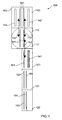
Figure 1 illustrates an embodiment of adeposition system 100. The system includes thefirst deposition chamber 101, asecond deposition chamber 102, and athird deposition chamber 103. Further, the system includes atransfer chamber 111, which is configured for transferring substrates from thefirst deposition chamber 101 to one of the second orthird deposition chambers 102/103. Further, thetransfer chamber 111 is configured for transferring the substrate from one of the second/third deposition chambers 102/103 to thefirst deposition chamber 101. - As shown in
figure 1 , thefirst deposition chamber 101 has afirst deposition source 141, and thesecond deposition chamber 102 and thethird deposition chamber 103 each have anotherdeposition source 142. Typically, thedeposition sources 142 in the second and the third chamber can be a similar deposition source such that thesecond deposition chamber 102 and thethird deposition chamber 103 can be used in an alternating manner. According to typical embodiments, which can be combined with other embodiments described herein, the deposition sources are provided as sputtering targets, such as rotatable sputtering targets. - Thereby, in the event the deposition with the
deposition source 142 is a limiting factor for the throughput of the in-line processing system 100, the overall throughput can be increased because substrates, which are continuously or quasi-continuously processed in the processing system, can be processed in the second/third deposition chambers deposition source 142 is a thick layer or if the deposition rate of adeposition source 142 is low. - According to embodiments described herein, the
transfer chamber 111 and thedeposition chambers linear transport paths processing system 100. Typically, thelinear transport paths transportation tracks 161, such as linear transportation tracks having, e.g., a plurality of rollers arranged along a line. According to typical embodiments, the transportation tracks 161 can be provided by a transportation system at the bottom of the large area substrates and a guiding system at the top of the essentially vertically oriented large area substrates. - According to yet further embodiments, which can be combined with other embodiments described herein, the
transfer chamber 111 can be a rotation module, particularly a vacuum rotation module, which is configured for rotation of the substrates with respect to a vertical rotational axis. This rotation is indicated byreference numeral 112. Thereby, a substrate entering thetransfer chamber 111 via thetransportation path 151 can be further transferred to thethird deposition chamber 103 viatransportation path 153 without a rotation in thetransfer chamber 111. A substrate which enters thetransfer chamber 111 via thetransportation path 151 can be a rotated within thetransfer chamber 111 in order to enter thesecond deposition chamber 102 viatransportation path 152. A transfer out of the second/third deposition chambers transfer chamber 111 can be conducted with or without a corresponding rotation, respectively. - As described above, the arrangement of
deposition chambers transfer chamber 111 can be used to improve the utilization of a plurality of deposition chambers, particularly of thedeposition chamber 101. Accordingly, if thedeposition chamber 101 is configured for deposition of expensive materials such as a molybdenum-containing material, a platinum-containing material, a gold-containing material, or a silver-containing material, an operator of theprocessing system 100 needs to purchase only one set of deposition sources of the expensive kind. Accordingly, the value of targets that need to be held on stock in order to enable short downtimes can be reduced. - According to embodiments described herein, the in-
line processing system 100 includes an improved utilization of the processing chambers and allows for feeding of the substrates into the processing system in a continuous or quasi-continuous manner. Thereby, thefurther chamber 121 and the yetfurther chamber 122 are provided with a first and asecond transportation track - The set of transportation tracks is configured for a lateral movement of a substrate within the
further chamber 121. Thereby, the substrate can be moved essentially horizontally such that a displacement along a direction perpendicular to the transportation paths. - According to typical embodiments, which can be combined with other embodiments described herein, the yet
further chamber 122 can be a load lock chamber for inserting the substrates into theprocessing system 100 and for discharging the substrates out of the processing system. Further, thefurther chamber 121 can be a chamber selected from the group consisting of: a buffer chamber, a heating chamber, a transfer chamber, a cycle-time-adjusting chamber, or the like. - According to typical embodiments, the chambers shown exemplarity in
figure 1 are vacuum chambers, i.e., they are configured for transferring or processing the substrates at the pressure of 10 mbar or below. Thereby, the substrates are locked into or locked out off the yetfurther chamber 122, which is configured for being evacuated before a vacuum valve betweenchambers further chamber 121 in theprocessing system 100. - According to different embodiments, several substrates can be processed in the processing system having an in-line processing system portion at the same time.
- According to typical embodiments, which can be combined with other embodiments described herein, the improved utilization of deposition chambers can be used for layer stacks, wherein the first layer and another layer, e.g., a final layer, are thin as compared to an intermediate layer. For example, a layer stack can include at least a molybdenum-containing layer, a copper-containing layer, and a molybdenum-containing layer, wherein these three layers included are provided in this order. The layer stack could also include a molybdenum-containing layer, an aluminum-containing layer, and a molybdenum containing layer, wherein these three layers included are provided in this order. Yet, according to further embodiments, the molybdenum-containing layer could also be another layer of the above-described layers including an expensive material.
- As illustrated with respect to
Fig. 2 , according to yet further embodiments, which can be combined with other embodiments described herein, afurther deposition chamber 204 and a yetfurther deposition chamber 205 can also be provided. Thereby thefurther deposition chambers transfer chamber 111. Thereby,linear transport paths further deposition chambers deposition sources 244 which may include a source for a yet further material. - Thereby, according to different implementations, the
deposition sources 244 can be of a similar kind such that essentially the same layer can be deposited infurther deposition chambers further deposition chambers - For example, a layer stack can include a thin molybdenum-containing layer, a thick layer comprising a first material, a thick layer comprising a second material, and a thin molybdenum-containing layer. Yet, according to further embodiments, the molybdenum-containing layer could also be another layer of the above-described layers including an expensive material. According to yet alternative embodiments, which can be combined with other embodiments described herein, the
further deposition chambers - According to another implementation, the
deposition sources 244 could be of the same kind asdeposition sources 142, such that an intermediate layer could be processed for an even longer time as compared to the embodiments shown infigure 1 . According to typical embodiments, which can be combined with other embodiments described herein, the deposition sources are provided as sputtering targets, such as rotatable sputtering targets. - According to yet further alternative implementations, the
deposition sources 244 could deposit different materials such that a layer stack with more than four layers to be deposited can be manufactured in the system. - According to yet further embodiments, which can be combined with other embodiments described herein, the processing systems, such as the
processing system 200 shown infigure 2 , can also have a transportation system with afirst transportation track 163, asecond transportation track 164 and one or more further transportation tracks, such as thethird transportation track 265, which is shown infurther chambers figure 2 . - Thereby, the substrates can be transferred from the yet further chamber (load lock chamber) 122 in the
further chamber 121, or one substrate can be transferred from thefurther chamber 121 in the yet further chamber (load lock chamber) 122 while another substrate is transferred from the yetfurther chamber 122 in thefurther chamber 121. Accordingly, a transfer of substrates can be conducted in a more flexible manner, such that applications for which the transfer of substrates might be a limiting factor for the cycle time can be increased in throughput. - An example of the
further chamber 121 with thefirst transportation track 163 and thesecond transportation track 164 is shown infigure 3 . Thefurther chamber 121 has achamber wall 302 withopenings 306. Theopenings 306 are configured for transfer of the essentially vertically-oriented substrates. Accordingly, theopenings 306 can have the shape of a slit. Typically, the openings can be opened and closed with a vacuum valve. - Further, the
further chamber 121 can have aflange 304 for connection of a vacuum system, such as a vacuum pump or the like. Thereby, thefurther chamber 121 can be evacuated when at least one of the vacuum valves, preferably both vacuum valves for closing theopenings 306, are closed. - The substrate transport system or carrier transport system, respectively, having a
first transportation track 163 and asecond transportation track 164 includes two groups of transportation elements. Thetransportation elements 310 of the first group of transportation elements include atransportation roller 312. Thetransportation elements 320 of the second group of transportation elements include atransportation roller 322. Thetransportation elements 310 are rotatable around therotation axis 311. Thetransportation elements 320 are rotatable around therotation axis 321. - Each of the
transportation elements figure 3 in two positions. Thereby, one position is shown with dotted lines. Each of the transportation elements has abearing element axis - As illustrated in
figure 3 , thetransportation roller 312 is offset with respect to thetransportation roller 322. By the linear movement of the transportation elements, thetransportation roller 312 of thetransportation elements 310 can move from thefirst transportation track 163 to thesecond transportation track 164. Accordingly, by movement of thetransportation elements second transportation track 164, can be moved to the first transportation track. - The
transportation elements figure 3 , provide the substrate support for the essentially vertically oriented substrate, which is adapted to support the substrate at the lower end thereof. According to further embodiments, which can be combined with other embodiments described herein, the substrate transportation system or the carrier transportation system, respectively, can also include an upper transportation means. - Typically, the transportation means is one or more groups of guiding elements for guiding the substrates in one of the first transportation path or the second transportation path. For example, the guiding elements can be magnetic guiding elements having a recess, e.g., two slits, through which the substrate can be transferred. According to yet further embodiments, these guiding elements can also include a bearing for linear movement such that the shift from the first transportation track to the second transportation track can be conducted.
- According to typical embodiments, the
transportation elements 310 and thetransportation elements 320 are moved synchronously for lateral transfer of the essentially vertically oriented substrate within thefurther chamber 121. Typically, the upper elements, such as the guiding elements, are also moved at the same time. - The
transportation elements -
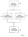
Figure 4 illustrates a method of depositing a layer stack in a hybrid system between an inline-processing system and a cluster processing system having an improved utilization of deposition chambers. As shown infigure 4 , a first layer is deposited in a first chamber instep 402. The first layer can typically include at least one material selected from the group consisting of: molybdenum, platinum, and gold. - Further, the first layer is typically a thin layer or a layer which can be deposited within a time that is short as compared to the deposition time of a second layer. The substrate is then transferred in either the second or the third chamber such that the second layer can be either deposited in the second chamber in
step 404 or third chamber instep 405. - Thereby, the
steps step 406 another layer comprising the same material as the first layer (see step 402) is deposited. Step 406 is conducted in the same chamber asstep 402. Thereby, an improved utilization of deposition chambers is provided. -
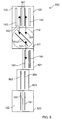
Figure 5 illustrates another embodiment of adeposition system 100. The system includes thefirst deposition chamber 101, asecond deposition chamber 102, and athird deposition chamber 103. Further, the system includes atransfer chamber 111, which is configured for transferring substrates from thefirst deposition chamber 101 to one of the second orthird deposition chambers 102/103. Further, thetransfer chamber 111 is configured for transferring the substrate from one of thedeposition chambers 102/103 to thefirst deposition chamber 101. - As shown in
figure 5 , thefirst deposition chamber 101 has afirst deposition source 141, and thesecond deposition chamber 102 and thethird deposition chamber 103 each have anotherdeposition source 142. Further details have been described with respect tofigure 1 above. - According to embodiments described herein, the
transfer chamber 111 and thedeposition chambers linear transport paths inline processing system 100. Typically, thelinear transport paths transportation tracks 161 such as linear transportation tracks having, e.g., a plurality of rollers arranged along a line. According to typical embodiments, the transportation tracks 161 can be provided by a transportation system at the bottom of the large area substrates and a guiding system at the top of the essentially vertically-oriented large area substrates. - According to yet further embodiments, which can be combined with other embodiments described herein, the
transfer chamber 111 can be a rotation module, particularly a vacuum rotation module, which is configured for rotation of the substrates with respect to a vertical rotational axis. This rotation is indicated byreference numeral 112. Thereby, a substrate entering thetransfer chamber 111 via thetransportation path 151 can be further transferred to thethird deposition chamber 103 viatransportation path 153 without a rotation in thetransfer chamber 111. A substrate which enters thetransfer chamber 111 via thetransportation path 151 can be a rotated within thetransfer chamber 111 in order to enter thesecond deposition chamber 102 viatransportation path 152. A transfer out of the second/third deposition chambers chamber 111 can be conducted with or without a corresponding rotation, respectively. - As described above, the arrangement of
deposition chambers transfer chamber 111 can be used to improve the utilization of a plurality of deposition chambers, particularly of thedeposition chamber 101. Accordingly, if thedeposition chamber 101 is configured for deposition of expensive materials such as a molybdenum-containing material, a platinum-containing material, a gold-containing material, or a silver-containing material, an operator of theprocessing system 100 needs to purchase only one set of deposition sources of the expensive kind. Accordingly, the value of targets that need to be held on stock in order to enable short downtimes can be reduced. - According to embodiments described herein, the
hybrid system 100 between an inline-processing system and a cluster processing system includes an improved utilization of the processing chambers and allows for feeding of the substrates into the processing system in a continuous or quasi-continuous manner. As shown inFigure 5 , according to further embodiments, which can be combined with other embodiments described herein, afurther chamber 521 andload lock chambers 122 and 522 (yet further chambers) are provided in theprocessing system 500. Thefurther chamber 521 has a first and asecond transportation track further chamber 521. Thereby, the substrate can be moved essentially horizontally such that a displacement along a direction perpendicular to the transportation paths occurs. - Accordingly, the lateral movement of the substrate can be used to transfer the substrates in either one of the first and the second load lock chambers, respectively. As compared to
Figure 1 , two load lock chambers are provided, which can be evacuated or vented individually. This might be helpful to further increase the throughput of the processing system. - In light of the above a plurality of embodiments are described. For example, according to one embodiment, a substrate processing system for processing an essentially vertically-oriented substrate is provided. The system includes a first processing chamber having a first processing region and being adapted to deposit a first layer comprising a first material, a second processing chamber having a second processing region and being adapted to deposit a second layer over the first layer, the second layer comprising a second material, a third processing chamber having a third processing region and being adapted to deposit a layer comprising the second material, a transfer chamber providing essentially linear transport paths with the first, the second, and the third chambers, respectively, and a further chamber comprising a first and a second transportation track, wherein at least one of the first and second transportation tracks forms an essentially linear transportation path with the first processing chamber, and wherein the first chamber is adapted to receive the substrate from the transfer chamber, and to deposit a further layer comprising the first material. According to further implementations, which can be combined with other embodiments described herein, the transfer chamber can be a rotation module, particularly a vacuum rotation module for rotation substrate under a pressure below 10 mbar; the system can include an inline processing system portion, particularly wherein the system can be a hybrid system between an inline-processing system and a cluster processing system; and/or the system can further include a lateral displacement mechanism configured for lateral displacement of the substrate from the first transportation track to the second transportation track and vice versa. For example, the lateral displacement mechanism can be disposed in the further chamber. According to yet further embodiments, which can be combined with other embodiments and implementations described herein, the system can further include one or more of the following features selected from the group consisting of: the system can further include at least one load lock chamber comprising further portions of each of the first and the second transportation track, wherein the further portions are provided in extension of the first and second transportation track in the further chamber; the system can further include at least one further chamber having a further processing region and being adapted to deposit a further layer comprising a third material, wherein the at last one further chamber is connected to the transfer chamber; the at least one further chamber can be at least two further chambers, each being adapted to deposit the layer comprising the third material; and the first material can be selected from the group consisting of: molybdenum, molybdenum-alloys, platinum, platinum-alloys, gold, gold-alloys, titanium, titanium-alloys, silver, and silver-alloys. For example, the first material can be molybdenum, a molybdenum-alloy, titanium, or a titanium-alloy. According to yet further embodiments, which can be combined with other embodiments and implementations described herein, the system can further include one or more of the following features selected from the group consisting of: the further chamber can include a third transportation track; the first transportation track can include a plurality of guiding elements for guiding in a transport direction, wherein the second transportation track can include a plurality of guiding elements for guiding in the transport direction, and wherein the guiding elements of the first transportation track and the second transportation track are adapted for a first and second guiding position respectively such that the guiding positions are displaced in a direction perpendicular to the transport direction; and the guiding elements of the first transportation track and the guiding elements of the second transportation track can be provided along the transportation direction alternately.
- According to a further embodiment, a method of depositing a layer stack in a substrate processing system having a first, a second, and a third processing chamber is provided. The method includes depositing a first layer comprising a first material in the first processing chamber over an essentially vertically oriented substrate, depositing a second layer comprising a second material in one chamber selected from: the second processing chamber and the third processing chamber, wherein the second chamber processing and the third processing chamber are used in an essentially alternating manner, depositing a third layer comprising the first material in the first processing chamber, wherein the first, the second, and the third processing chambers are connected to a transfer chamber with essentially linear transport paths, and laterally displacing a substrate between a first transportation track and a second transportation track in a further chamber.
- According to typical modifications thereof the first layer on a first substrate can be deposited while the second layer on another substrate is deposited; the method can further include transferring two substrates simultaneously onto or off the first transportation track and the second transportation track; and/or the first material can be selected from the group consisting of: molybdenum, molybdenum-alloys, platinum, platinum-alloys, gold, gold-alloys, titanium, titanium-alloys, silver, and silver-alloys. For example, the first material can be molybdenum, a molybdenum-alloy, titanium, or a titanium-alloy.
- While the foregoing is directed to embodiments of the invention, other and further embodiments of the invention may be devised without departing from the basic scope thereof, and the scope thereof is determined by the claims that follow.
Claims (13)
- A substrate processing system for processing an essentially vertically-oriented substrate, comprising:a first processing chamber (101) having a first processing region and being adapted to deposit a first layer comprising a first material;a second processing chamber (102) having a second processing region and being adapted to deposit a second layer over the first layer, the second layer comprising a second material;a third processing chamber (103) having a third processing region and being adapted to deposit a layer comprising the second material;a transfer chamber (111) providing linear transport paths (151, 152, 153) with the first, the second, and the third chambers, respectively;a further chamber (121) comprising a first and a second transportation track (163, 164), wherein at least one of the first and second transportation tracks forms a linear transportation path with the first processing chamber;a lateral displacement mechanism configured for lateral displacement of the substrate from the first transportation track to the second transportation track and vice versa, particularly wherein the lateral displacement mechanism is disposed in the further chamber; andat least one load lock chamber (122) comprising further portions of each of the first and the second transportation track (163, 164), wherein the further portions are provided in extension of the first and second transportation track in the further chamber (121),wherein the first chamber is adapted to receive the substrate from the transfer chamber, and to deposit a further layer comprising the first material.
- The system according to claim 1, wherein the transfer chamber (111) is a rotation module, particularly a vacuum rotation module for rotation substrate under a pressure below 10 mbar.
- The system according to any of claims 1 to 2, wherein the system comprises an inline processing system portion, particularly wherein the system is a hybrid system between an inline-processing system and a cluster processing system.
- The system according to any of claims 1 to 3, further comprising:at least one further deposition chamber (204, 205) having a further processing region and being adapted to deposit a further layer comprising a third material, wherein the at last one further deposition chamber is connected to the transfer chamber.
- The system according to claim 4, wherein the at least one further deposition chamber are at least two further deposition chambers (204, 205), each being adapted to deposit the layer comprising the third material.
- The system according to any of claims 1 to 5, wherein the first material is selected from the group consisting of: molybdenum, molybdenum-alloys, platinum, platinum-alloys, gold, gold-alloys, titanium, titanium-alloys, silver, and silver-alloys, particularly wherein the first material is molybdenum, a molybdenum-alloy, titanium, or a titanium-alloy.
- The system according to any of claims 1 to 6, wherein the further chamber comprises a third transportation track.
- The system according to any of claims 1 to 7, wherein the first transportation track comprises a plurality of guiding elements for guiding in a transport direction, wherein the second transportation track comprises a plurality of guiding elements for guiding in the transport direction, and wherein the guiding elements of the first transportation track and the second transportation track are adapted for a first and second guiding position respectively such that the guiding positions are displaced in a direction perpendicular to the transport direction.
- The system according to claim 8, wherein the guiding elements of the first transportation track and the guiding elements of the second transportation track are provided along the transportation direction alternately.
- A method of depositing a layer stack in a substrate processing system having a first, a second, and a third processing chamber (101, 102, 103), the method comprising:depositing a first layer comprising a first material in the first processing chamber (101) over an essentially vertically oriented substrate;depositing a second layer comprising a second material in one chamber selected from: the second processing chamber (102) and the third processing chamber (103), wherein the second chamber processing and the third processing chamber are used in an alternating manner; anddepositing a third layer comprising the first material in the first processing chamber (101), wherein the first, the second, and the third processing chambers are connected to a transfer chamber with linear transport paths; andlaterally displacing a substrate between a first transportation track (163) and a second transportation track (164) in a further chamber (121), whereinfurther portions of each of the first and the second transportation track (163, 164) are comprised in at least one load lock chamber (122), wherein the further portions are provided in extension of the first and second transportation track in the further chamber (121).
- The method of claim 10, wherein the first layer on a first substrate is deposited while the second layer on another substrate is deposited.
- The method of any one of claims 10 to 11, further comprising:transferring two substrates simultaneously onto or off the first transportation track (163) and the second transportation track (164).
- The method of any one of claims 10 to 12, wherein the first material is selected from the group consisting of: molybdenum, molybdenum-alloys, platinum, platinum-alloys, gold, gold-alloys, titanium, titanium-alloys, silver, and silver-alloys, particularly wherein the first material is molybdenum, a molybdenum-alloy, titanium, or a titanium-alloy.
Priority Applications (10)
| Application Number | Priority Date | Filing Date | Title |
|---|---|---|---|
| EP11155238.6A EP2489759B1 (en) | 2011-02-21 | 2011-02-21 | System for utilization improvement of process chambers and method of operating thereof |
| US13/036,265 US20120213938A1 (en) | 2011-02-21 | 2011-02-28 | System for utilization improvement of process chambers and method of operating thereof |
| EP12706232.1A EP2678462B1 (en) | 2011-02-21 | 2012-02-21 | Coating apparatus and method. |
| KR1020137024539A KR102095717B1 (en) | 2011-02-21 | 2012-02-21 | Coating apparatus and method |
| TW101105674A TWI579952B (en) | 2011-02-21 | 2012-02-21 | System for utilization improvement of process chambers and method of operating thereof |
| JP2013553970A JP5945553B2 (en) | 2011-02-21 | 2012-02-21 | Coating apparatus and coating method |
| CN201280000407.3A CN102803551B (en) | 2011-02-21 | 2012-02-21 | For improving system and the working method thereof for the treatment of chamber utilization |
| PCT/EP2012/052935 WO2012113792A1 (en) | 2011-02-21 | 2012-02-21 | Coating apparatus and method. |
| KR1020197013377A KR20190053293A (en) | 2011-02-21 | 2012-02-21 | Coating apparatus and method |
| US14/000,369 US9211563B2 (en) | 2011-02-21 | 2012-02-21 | Coating apparatus and method |
Applications Claiming Priority (1)
| Application Number | Priority Date | Filing Date | Title |
|---|---|---|---|
| EP11155238.6A EP2489759B1 (en) | 2011-02-21 | 2011-02-21 | System for utilization improvement of process chambers and method of operating thereof |
Publications (2)
| Publication Number | Publication Date |
|---|---|
| EP2489759A1 EP2489759A1 (en) | 2012-08-22 |
| EP2489759B1 true EP2489759B1 (en) | 2014-12-10 |
Family
ID=44243134
Family Applications (2)
| Application Number | Title | Priority Date | Filing Date |
|---|---|---|---|
| EP11155238.6A Not-in-force EP2489759B1 (en) | 2011-02-21 | 2011-02-21 | System for utilization improvement of process chambers and method of operating thereof |
| EP12706232.1A Not-in-force EP2678462B1 (en) | 2011-02-21 | 2012-02-21 | Coating apparatus and method. |
Family Applications After (1)
| Application Number | Title | Priority Date | Filing Date |
|---|---|---|---|
| EP12706232.1A Not-in-force EP2678462B1 (en) | 2011-02-21 | 2012-02-21 | Coating apparatus and method. |
Country Status (7)
| Country | Link |
|---|---|
| US (2) | US20120213938A1 (en) |
| EP (2) | EP2489759B1 (en) |
| JP (1) | JP5945553B2 (en) |
| KR (2) | KR20190053293A (en) |
| CN (1) | CN102803551B (en) |
| TW (1) | TWI579952B (en) |
| WO (1) | WO2012113792A1 (en) |
Families Citing this family (21)
| Publication number | Priority date | Publication date | Assignee | Title |
|---|---|---|---|---|
| TWI468538B (en) * | 2011-10-14 | 2015-01-11 | Chenming Mold Ind Corp | Method for manufacturing shielding |
| EP2892834B1 (en) * | 2012-09-10 | 2018-05-02 | Applied Materials, Inc. | Substrate transfer device and method of moving substrates |
| TWI582256B (en) | 2013-02-04 | 2017-05-11 | 愛發科股份有限公司 | Thin substrate processing apparatus |
| KR20160138295A (en) * | 2014-04-02 | 2016-12-02 | 어플라이드 머티어리얼스, 인코포레이티드 | System for substrate processing, vacuum rotation module for a system for substrate processing and method of operating a substrate processing system |
| TWI557837B (en) * | 2014-04-10 | 2016-11-11 | Uvat Technology Co Ltd | Vacuum equipment multi-vehicle simultaneous multi-processing process |
| TWI732285B (en) * | 2015-01-23 | 2021-07-01 | 美商應用材料股份有限公司 | Semiconductor process equipment |
| CN208240622U (en) * | 2015-05-22 | 2018-12-14 | 应用材料公司 | For loading and unloading the load lock chamber and array base plate processing system of carried base board |
| US9972740B2 (en) | 2015-06-07 | 2018-05-15 | Tesla, Inc. | Chemical vapor deposition tool and process for fabrication of photovoltaic structures |
| DE102015013799A1 (en) * | 2015-10-26 | 2017-04-27 | Grenzebach Maschinenbau Gmbh | Apparatus and method for coating overlong planar substrates, in particular glass panes, in a vacuum coating installation |
| CN105239051B (en) * | 2015-11-17 | 2018-11-30 | 广东腾胜真空技术工程有限公司 | Two-way disengaging alternate plating device and method |
| US9748434B1 (en) | 2016-05-24 | 2017-08-29 | Tesla, Inc. | Systems, method and apparatus for curing conductive paste |
| US9954136B2 (en) | 2016-08-03 | 2018-04-24 | Tesla, Inc. | Cassette optimized for an inline annealing system |
| JP6830772B2 (en) * | 2016-08-04 | 2021-02-17 | 株式会社ジャパンディスプレイ | Laminated film manufacturing equipment and laminated film manufacturing method |
| US10115856B2 (en) | 2016-10-31 | 2018-10-30 | Tesla, Inc. | System and method for curing conductive paste using induction heating |
| KR20180086715A (en) * | 2017-01-23 | 2018-08-01 | 어플라이드 머티어리얼스, 인코포레이티드 | Transfer module, substrate processing system having the same and substrate processing mehtod using the same |
| US10043693B1 (en) * | 2017-06-06 | 2018-08-07 | Applied Materials, Inc. | Method and apparatus for handling substrates in a processing system having a buffer chamber |
| CN114127331A (en) * | 2019-07-25 | 2022-03-01 | 应用材料公司 | Substrate processing system for processing a plurality of substrates and method of processing substrates in an inline substrate processing system |
| EP4094306A4 (en) | 2020-01-22 | 2024-02-28 | Applied Materials, Inc. | In-line monitoring of oled layer thickness and dopant concentration |
| US11889740B2 (en) * | 2020-01-22 | 2024-01-30 | Applied Materials, Inc. | In-line monitoring of OLED layer thickness and dopant concentration |
| WO2023174510A1 (en) * | 2022-03-14 | 2023-09-21 | Applied Materials, Inc. | Vacuum deposition system and method of coating substrates in a vacuum deposition system |
| TWI843196B (en) * | 2022-09-08 | 2024-05-21 | 凌嘉科技股份有限公司 | Rotary transfer vertical coating equipment and double-sided multi-layer coating method |
Citations (1)
| Publication number | Priority date | Publication date | Assignee | Title |
|---|---|---|---|---|
| FR2230167A5 (en) * | 1973-05-17 | 1974-12-13 | Globe Amerada Glass Co | Metal-coated glass - e.g. dichroic windows, using molecular-bonded metal layer |
Family Cites Families (13)
| Publication number | Priority date | Publication date | Assignee | Title |
|---|---|---|---|---|
| US4526670A (en) * | 1983-05-20 | 1985-07-02 | Lfe Corporation | Automatically loadable multifaceted electrode with load lock mechanism |
| US7207766B2 (en) * | 2003-10-20 | 2007-04-24 | Applied Materials, Inc. | Load lock chamber for large area substrate processing system |
| KR101270526B1 (en) * | 2004-05-26 | 2013-06-04 | 가부시키가이샤 아루박 | Vacuum process apparatus |
| JP4754791B2 (en) * | 2004-08-04 | 2011-08-24 | 株式会社アルバック | Vacuum processing equipment |
| KR100667886B1 (en) * | 2005-07-01 | 2007-01-11 | 주식회사 에스에프에이 | In-line sputtering system |
| JP4711770B2 (en) * | 2005-08-01 | 2011-06-29 | 株式会社アルバック | Conveying apparatus, vacuum processing apparatus, and conveying method |
| KR101225312B1 (en) * | 2005-12-16 | 2013-01-22 | 엘지디스플레이 주식회사 | Process apparatus |
| DE102005061563A1 (en) * | 2005-12-22 | 2007-07-19 | Applied Materials Gmbh & Co. Kg | Plant for the treatment of substrates and processes |
| DE502007004989D1 (en) * | 2007-02-09 | 2010-10-21 | Applied Materials Inc | Plant with a transport device for the treatment of substrates |
| JP2008199021A (en) * | 2007-02-09 | 2008-08-28 | Applied Materials Inc | Conveyance device in substrate processing equipment |
| KR20100132517A (en) * | 2008-03-05 | 2010-12-17 | 어플라이드 머티어리얼스, 인코포레이티드 | Coating apparatus with rotation module |
| US9353436B2 (en) * | 2008-03-05 | 2016-05-31 | Applied Materials, Inc. | Coating apparatus with rotation module |
| CN102057076B (en) * | 2008-06-09 | 2013-03-06 | 应用材料公司 | Coating system and method for coating a substrate |
-
2011
- 2011-02-21 EP EP11155238.6A patent/EP2489759B1/en not_active Not-in-force
- 2011-02-28 US US13/036,265 patent/US20120213938A1/en not_active Abandoned
-
2012
- 2012-02-21 CN CN201280000407.3A patent/CN102803551B/en active Active
- 2012-02-21 US US14/000,369 patent/US9211563B2/en active Active
- 2012-02-21 TW TW101105674A patent/TWI579952B/en not_active IP Right Cessation
- 2012-02-21 KR KR1020197013377A patent/KR20190053293A/en not_active Application Discontinuation
- 2012-02-21 JP JP2013553970A patent/JP5945553B2/en not_active Expired - Fee Related
- 2012-02-21 WO PCT/EP2012/052935 patent/WO2012113792A1/en active Application Filing
- 2012-02-21 EP EP12706232.1A patent/EP2678462B1/en not_active Not-in-force
- 2012-02-21 KR KR1020137024539A patent/KR102095717B1/en active IP Right Grant
Patent Citations (1)
| Publication number | Priority date | Publication date | Assignee | Title |
|---|---|---|---|---|
| FR2230167A5 (en) * | 1973-05-17 | 1974-12-13 | Globe Amerada Glass Co | Metal-coated glass - e.g. dichroic windows, using molecular-bonded metal layer |
Also Published As
| Publication number | Publication date |
|---|---|
| KR20190053293A (en) | 2019-05-17 |
| US20120213938A1 (en) | 2012-08-23 |
| JP5945553B2 (en) | 2016-07-05 |
| CN102803551A (en) | 2012-11-28 |
| CN102803551B (en) | 2016-03-16 |
| TW201248760A (en) | 2012-12-01 |
| US9211563B2 (en) | 2015-12-15 |
| WO2012113792A1 (en) | 2012-08-30 |
| JP2014507565A (en) | 2014-03-27 |
| KR20140015372A (en) | 2014-02-06 |
| EP2678462B1 (en) | 2017-07-26 |
| KR102095717B1 (en) | 2020-04-01 |
| EP2678462A1 (en) | 2014-01-01 |
| EP2489759A1 (en) | 2012-08-22 |
| TWI579952B (en) | 2017-04-21 |
| US20140044880A1 (en) | 2014-02-13 |
Similar Documents
| Publication | Publication Date | Title |
|---|---|---|
| EP2489759B1 (en) | System for utilization improvement of process chambers and method of operating thereof | |
| WO2015149848A1 (en) | System for substrate processing, vacuum rotation module for a system for substrate processing and method of operating a substrate processing system | |
| US20090324368A1 (en) | Processing system and method of operating a processing system | |
| EP2892834B1 (en) | Substrate transfer device and method of moving substrates | |
| US20100272550A1 (en) | Substrate holding mechanism, substrate delivering/receiving mechanism, and substrate processing apparatus | |
| CN105026611B (en) | Device and its operating method with adjacent sputter cathode | |
| JP6211086B2 (en) | Substrate processing system and method for processing a substrate | |
| JP5657527B2 (en) | Coating system and method for coating a substrate | |
| EP2297376A1 (en) | Processing system and method of operating a processing system | |
| US20090304907A1 (en) | Coating system and method for coating a substrate | |
| CN208240622U (en) | For loading and unloading the load lock chamber and array base plate processing system of carried base board | |
| JP6055229B2 (en) | To-be-processed object conveyance mechanism and vacuum processing apparatus | |
| EP2133445B1 (en) | Coating System and Method for Coating a Substrate | |
| US8534976B2 (en) | Apparatus for providing a rotation carrier magazine, and method of operating thereof | |
| EP2141258A1 (en) | Processing system and method of operating a processing system |
Legal Events
| Date | Code | Title | Description |
|---|---|---|---|
| PUAI | Public reference made under article 153(3) epc to a published international application that has entered the european phase |
Free format text: ORIGINAL CODE: 0009012 |
|
| AK | Designated contracting states |
Kind code of ref document: A1 Designated state(s): AL AT BE BG CH CY CZ DE DK EE ES FI FR GB GR HR HU IE IS IT LI LT LU LV MC MK MT NL NO PL PT RO RS SE SI SK SM TR |
|
| AX | Request for extension of the european patent |
Extension state: BA ME |
|
| 17P | Request for examination filed |
Effective date: 20130222 |
|
| RIN1 | Information on inventor provided before grant (corrected) |
Inventor name: KOPARAL, ERKAN |
|
| 17Q | First examination report despatched |
Effective date: 20130528 |
|
| RIC1 | Information provided on ipc code assigned before grant |
Ipc: H01L 21/677 20060101ALI20140513BHEP Ipc: C23C 14/56 20060101AFI20140513BHEP Ipc: H01L 21/67 20060101ALI20140513BHEP Ipc: B05D 7/00 20060101ALI20140513BHEP Ipc: B05C 13/00 20060101ALI20140513BHEP Ipc: C03C 17/00 20060101ALI20140513BHEP |
|
| GRAP | Despatch of communication of intention to grant a patent |
Free format text: ORIGINAL CODE: EPIDOSNIGR1 |
|
| INTG | Intention to grant announced |
Effective date: 20140711 |
|
| GRAS | Grant fee paid |
Free format text: ORIGINAL CODE: EPIDOSNIGR3 |
|
| GRAA | (expected) grant |
Free format text: ORIGINAL CODE: 0009210 |
|
| AK | Designated contracting states |
Kind code of ref document: B1 Designated state(s): AL AT BE BG CH CY CZ DE DK EE ES FI FR GB GR HR HU IE IS IT LI LT LU LV MC MK MT NL NO PL PT RO RS SE SI SK SM TR |
|
| REG | Reference to a national code |
Ref country code: GB Ref legal event code: FG4D |
|
| REG | Reference to a national code |
Ref country code: CH Ref legal event code: EP |
|
| REG | Reference to a national code |
Ref country code: IE Ref legal event code: FG4D |
|
| REG | Reference to a national code |
Ref country code: AT Ref legal event code: REF Ref document number: 700715 Country of ref document: AT Kind code of ref document: T Effective date: 20150115 |
|
| REG | Reference to a national code |
Ref country code: DE Ref legal event code: R096 Ref document number: 602011012060 Country of ref document: DE Effective date: 20150122 |
|
| REG | Reference to a national code |
Ref country code: CH Ref legal event code: NV Representative=s name: MICHELI AND CIE SA, CH |
|
| REG | Reference to a national code |
Ref country code: NL Ref legal event code: T3 |
|
| REG | Reference to a national code |
Ref country code: AT Ref legal event code: MK05 Ref document number: 700715 Country of ref document: AT Kind code of ref document: T Effective date: 20141210 |
|
| PG25 | Lapsed in a contracting state [announced via postgrant information from national office to epo] |
Ref country code: NO Free format text: LAPSE BECAUSE OF FAILURE TO SUBMIT A TRANSLATION OF THE DESCRIPTION OR TO PAY THE FEE WITHIN THE PRESCRIBED TIME-LIMIT Effective date: 20150310 Ref country code: LT Free format text: LAPSE BECAUSE OF FAILURE TO SUBMIT A TRANSLATION OF THE DESCRIPTION OR TO PAY THE FEE WITHIN THE PRESCRIBED TIME-LIMIT Effective date: 20141210 Ref country code: ES Free format text: LAPSE BECAUSE OF FAILURE TO SUBMIT A TRANSLATION OF THE DESCRIPTION OR TO PAY THE FEE WITHIN THE PRESCRIBED TIME-LIMIT Effective date: 20141210 Ref country code: FI Free format text: LAPSE BECAUSE OF FAILURE TO SUBMIT A TRANSLATION OF THE DESCRIPTION OR TO PAY THE FEE WITHIN THE PRESCRIBED TIME-LIMIT Effective date: 20141210 |
|
| REG | Reference to a national code |
Ref country code: LT Ref legal event code: MG4D |
|
| PG25 | Lapsed in a contracting state [announced via postgrant information from national office to epo] |
Ref country code: SE Free format text: LAPSE BECAUSE OF FAILURE TO SUBMIT A TRANSLATION OF THE DESCRIPTION OR TO PAY THE FEE WITHIN THE PRESCRIBED TIME-LIMIT Effective date: 20141210 Ref country code: HR Free format text: LAPSE BECAUSE OF FAILURE TO SUBMIT A TRANSLATION OF THE DESCRIPTION OR TO PAY THE FEE WITHIN THE PRESCRIBED TIME-LIMIT Effective date: 20141210 Ref country code: RS Free format text: LAPSE BECAUSE OF FAILURE TO SUBMIT A TRANSLATION OF THE DESCRIPTION OR TO PAY THE FEE WITHIN THE PRESCRIBED TIME-LIMIT Effective date: 20141210 Ref country code: GR Free format text: LAPSE BECAUSE OF FAILURE TO SUBMIT A TRANSLATION OF THE DESCRIPTION OR TO PAY THE FEE WITHIN THE PRESCRIBED TIME-LIMIT Effective date: 20150311 Ref country code: LV Free format text: LAPSE BECAUSE OF FAILURE TO SUBMIT A TRANSLATION OF THE DESCRIPTION OR TO PAY THE FEE WITHIN THE PRESCRIBED TIME-LIMIT Effective date: 20141210 Ref country code: AT Free format text: LAPSE BECAUSE OF FAILURE TO SUBMIT A TRANSLATION OF THE DESCRIPTION OR TO PAY THE FEE WITHIN THE PRESCRIBED TIME-LIMIT Effective date: 20141210 |
|
| PG25 | Lapsed in a contracting state [announced via postgrant information from national office to epo] |
Ref country code: PT Free format text: LAPSE BECAUSE OF FAILURE TO SUBMIT A TRANSLATION OF THE DESCRIPTION OR TO PAY THE FEE WITHIN THE PRESCRIBED TIME-LIMIT Effective date: 20150410 Ref country code: EE Free format text: LAPSE BECAUSE OF FAILURE TO SUBMIT A TRANSLATION OF THE DESCRIPTION OR TO PAY THE FEE WITHIN THE PRESCRIBED TIME-LIMIT Effective date: 20141210 Ref country code: CZ Free format text: LAPSE BECAUSE OF FAILURE TO SUBMIT A TRANSLATION OF THE DESCRIPTION OR TO PAY THE FEE WITHIN THE PRESCRIBED TIME-LIMIT Effective date: 20141210 Ref country code: RO Free format text: LAPSE BECAUSE OF FAILURE TO SUBMIT A TRANSLATION OF THE DESCRIPTION OR TO PAY THE FEE WITHIN THE PRESCRIBED TIME-LIMIT Effective date: 20141210 Ref country code: SK Free format text: LAPSE BECAUSE OF FAILURE TO SUBMIT A TRANSLATION OF THE DESCRIPTION OR TO PAY THE FEE WITHIN THE PRESCRIBED TIME-LIMIT Effective date: 20141210 |
|
| PG25 | Lapsed in a contracting state [announced via postgrant information from national office to epo] |
Ref country code: PL Free format text: LAPSE BECAUSE OF FAILURE TO SUBMIT A TRANSLATION OF THE DESCRIPTION OR TO PAY THE FEE WITHIN THE PRESCRIBED TIME-LIMIT Effective date: 20141210 Ref country code: IS Free format text: LAPSE BECAUSE OF FAILURE TO SUBMIT A TRANSLATION OF THE DESCRIPTION OR TO PAY THE FEE WITHIN THE PRESCRIBED TIME-LIMIT Effective date: 20150410 |
|
| REG | Reference to a national code |
Ref country code: DE Ref legal event code: R097 Ref document number: 602011012060 Country of ref document: DE |
|
| PG25 | Lapsed in a contracting state [announced via postgrant information from national office to epo] |
Ref country code: LU Free format text: LAPSE BECAUSE OF FAILURE TO SUBMIT A TRANSLATION OF THE DESCRIPTION OR TO PAY THE FEE WITHIN THE PRESCRIBED TIME-LIMIT Effective date: 20150221 |
|
| PLBE | No opposition filed within time limit |
Free format text: ORIGINAL CODE: 0009261 |
|
| STAA | Information on the status of an ep patent application or granted ep patent |
Free format text: STATUS: NO OPPOSITION FILED WITHIN TIME LIMIT |
|
| PG25 | Lapsed in a contracting state [announced via postgrant information from national office to epo] |
Ref country code: DK Free format text: LAPSE BECAUSE OF FAILURE TO SUBMIT A TRANSLATION OF THE DESCRIPTION OR TO PAY THE FEE WITHIN THE PRESCRIBED TIME-LIMIT Effective date: 20141210 Ref country code: MC Free format text: LAPSE BECAUSE OF FAILURE TO SUBMIT A TRANSLATION OF THE DESCRIPTION OR TO PAY THE FEE WITHIN THE PRESCRIBED TIME-LIMIT Effective date: 20141210 |
|
| 26N | No opposition filed |
Effective date: 20150911 |
|
| REG | Reference to a national code |
Ref country code: IE Ref legal event code: MM4A |
|
| PG25 | Lapsed in a contracting state [announced via postgrant information from national office to epo] |
Ref country code: IT Free format text: LAPSE BECAUSE OF FAILURE TO SUBMIT A TRANSLATION OF THE DESCRIPTION OR TO PAY THE FEE WITHIN THE PRESCRIBED TIME-LIMIT Effective date: 20141210 |
|
| PG25 | Lapsed in a contracting state [announced via postgrant information from national office to epo] |
Ref country code: IE Free format text: LAPSE BECAUSE OF NON-PAYMENT OF DUE FEES Effective date: 20150221 |
|
| REG | Reference to a national code |
Ref country code: FR Ref legal event code: PLFP Year of fee payment: 6 |
|
| PG25 | Lapsed in a contracting state [announced via postgrant information from national office to epo] |
Ref country code: SI Free format text: LAPSE BECAUSE OF FAILURE TO SUBMIT A TRANSLATION OF THE DESCRIPTION OR TO PAY THE FEE WITHIN THE PRESCRIBED TIME-LIMIT Effective date: 20141210 |
|
| PG25 | Lapsed in a contracting state [announced via postgrant information from national office to epo] |
Ref country code: MT Free format text: LAPSE BECAUSE OF FAILURE TO SUBMIT A TRANSLATION OF THE DESCRIPTION OR TO PAY THE FEE WITHIN THE PRESCRIBED TIME-LIMIT Effective date: 20141210 |
|
| REG | Reference to a national code |
Ref country code: FR Ref legal event code: PLFP Year of fee payment: 7 |
|
| PG25 | Lapsed in a contracting state [announced via postgrant information from national office to epo] |
Ref country code: BG Free format text: LAPSE BECAUSE OF FAILURE TO SUBMIT A TRANSLATION OF THE DESCRIPTION OR TO PAY THE FEE WITHIN THE PRESCRIBED TIME-LIMIT Effective date: 20141210 Ref country code: SM Free format text: LAPSE BECAUSE OF FAILURE TO SUBMIT A TRANSLATION OF THE DESCRIPTION OR TO PAY THE FEE WITHIN THE PRESCRIBED TIME-LIMIT Effective date: 20141210 Ref country code: HU Free format text: LAPSE BECAUSE OF FAILURE TO SUBMIT A TRANSLATION OF THE DESCRIPTION OR TO PAY THE FEE WITHIN THE PRESCRIBED TIME-LIMIT; INVALID AB INITIO Effective date: 20110221 |
|
| PG25 | Lapsed in a contracting state [announced via postgrant information from national office to epo] |
Ref country code: CY Free format text: LAPSE BECAUSE OF FAILURE TO SUBMIT A TRANSLATION OF THE DESCRIPTION OR TO PAY THE FEE WITHIN THE PRESCRIBED TIME-LIMIT Effective date: 20141210 |
|
| PG25 | Lapsed in a contracting state [announced via postgrant information from national office to epo] |
Ref country code: TR Free format text: LAPSE BECAUSE OF FAILURE TO SUBMIT A TRANSLATION OF THE DESCRIPTION OR TO PAY THE FEE WITHIN THE PRESCRIBED TIME-LIMIT Effective date: 20141210 |
|
| REG | Reference to a national code |
Ref country code: FR Ref legal event code: PLFP Year of fee payment: 8 |
|
| PG25 | Lapsed in a contracting state [announced via postgrant information from national office to epo] |
Ref country code: MK Free format text: LAPSE BECAUSE OF FAILURE TO SUBMIT A TRANSLATION OF THE DESCRIPTION OR TO PAY THE FEE WITHIN THE PRESCRIBED TIME-LIMIT Effective date: 20141210 |
|
| PG25 | Lapsed in a contracting state [announced via postgrant information from national office to epo] |
Ref country code: AL Free format text: LAPSE BECAUSE OF FAILURE TO SUBMIT A TRANSLATION OF THE DESCRIPTION OR TO PAY THE FEE WITHIN THE PRESCRIBED TIME-LIMIT Effective date: 20141210 |
|
| PGFP | Annual fee paid to national office [announced via postgrant information from national office to epo] |
Ref country code: NL Payment date: 20190218 Year of fee payment: 9 |
|
| PGFP | Annual fee paid to national office [announced via postgrant information from national office to epo] |
Ref country code: DE Payment date: 20190219 Year of fee payment: 9 Ref country code: GB Payment date: 20190218 Year of fee payment: 9 |
|
| PGFP | Annual fee paid to national office [announced via postgrant information from national office to epo] |
Ref country code: FR Payment date: 20190220 Year of fee payment: 9 |
|
| PGFP | Annual fee paid to national office [announced via postgrant information from national office to epo] |
Ref country code: CH Payment date: 20200219 Year of fee payment: 10 Ref country code: BE Payment date: 20200219 Year of fee payment: 10 |
|
| REG | Reference to a national code |
Ref country code: DE Ref legal event code: R119 Ref document number: 602011012060 Country of ref document: DE |
|
| REG | Reference to a national code |
Ref country code: NL Ref legal event code: MM Effective date: 20200301 |
|
| GBPC | Gb: european patent ceased through non-payment of renewal fee |
Effective date: 20200221 |
|
| PG25 | Lapsed in a contracting state [announced via postgrant information from national office to epo] |
Ref country code: NL Free format text: LAPSE BECAUSE OF NON-PAYMENT OF DUE FEES Effective date: 20200301 |
|
| PG25 | Lapsed in a contracting state [announced via postgrant information from national office to epo] |
Ref country code: DE Free format text: LAPSE BECAUSE OF NON-PAYMENT OF DUE FEES Effective date: 20200901 Ref country code: GB Free format text: LAPSE BECAUSE OF NON-PAYMENT OF DUE FEES Effective date: 20200221 Ref country code: FR Free format text: LAPSE BECAUSE OF NON-PAYMENT OF DUE FEES Effective date: 20200229 |
|
| REG | Reference to a national code |
Ref country code: BE Ref legal event code: MM Effective date: 20210228 |
|
| PG25 | Lapsed in a contracting state [announced via postgrant information from national office to epo] |
Ref country code: LI Free format text: LAPSE BECAUSE OF NON-PAYMENT OF DUE FEES Effective date: 20210228 Ref country code: CH Free format text: LAPSE BECAUSE OF NON-PAYMENT OF DUE FEES Effective date: 20210228 |
|
| PG25 | Lapsed in a contracting state [announced via postgrant information from national office to epo] |
Ref country code: BE Free format text: LAPSE BECAUSE OF NON-PAYMENT OF DUE FEES Effective date: 20210228 |