EP2489321A1 - Energieabgabevorrichtung mit einer Ultraschallwandleranordnung und einer phasengesteuerten Gruppenantenne - Google Patents
Energieabgabevorrichtung mit einer Ultraschallwandleranordnung und einer phasengesteuerten Gruppenantenne Download PDFInfo
- Publication number
- EP2489321A1 EP2489321A1 EP12000984A EP12000984A EP2489321A1 EP 2489321 A1 EP2489321 A1 EP 2489321A1 EP 12000984 A EP12000984 A EP 12000984A EP 12000984 A EP12000984 A EP 12000984A EP 2489321 A1 EP2489321 A1 EP 2489321A1
- Authority
- EP
- European Patent Office
- Prior art keywords
- medical device
- tissue
- user
- antenna array
- phased antenna
- Prior art date
- Legal status (The legal status is an assumption and is not a legal conclusion. Google has not performed a legal analysis and makes no representation as to the accuracy of the status listed.)
- Granted
Links
Images


Classifications
-
- A—HUMAN NECESSITIES
- A61—MEDICAL OR VETERINARY SCIENCE; HYGIENE
- A61B—DIAGNOSIS; SURGERY; IDENTIFICATION
- A61B18/00—Surgical instruments, devices or methods for transferring non-mechanical forms of energy to or from the body
- A61B18/18—Surgical instruments, devices or methods for transferring non-mechanical forms of energy to or from the body by applying electromagnetic radiation, e.g. microwaves
- A61B18/1815—Surgical instruments, devices or methods for transferring non-mechanical forms of energy to or from the body by applying electromagnetic radiation, e.g. microwaves using microwaves
-
- A—HUMAN NECESSITIES
- A61—MEDICAL OR VETERINARY SCIENCE; HYGIENE
- A61B—DIAGNOSIS; SURGERY; IDENTIFICATION
- A61B8/00—Diagnosis using ultrasonic, sonic or infrasonic waves
-
- A—HUMAN NECESSITIES
- A61—MEDICAL OR VETERINARY SCIENCE; HYGIENE
- A61B—DIAGNOSIS; SURGERY; IDENTIFICATION
- A61B8/00—Diagnosis using ultrasonic, sonic or infrasonic waves
- A61B8/44—Constructional features of the ultrasonic, sonic or infrasonic diagnostic device
- A61B8/4444—Constructional features of the ultrasonic, sonic or infrasonic diagnostic device related to the probe
-
- A—HUMAN NECESSITIES
- A61—MEDICAL OR VETERINARY SCIENCE; HYGIENE
- A61B—DIAGNOSIS; SURGERY; IDENTIFICATION
- A61B18/00—Surgical instruments, devices or methods for transferring non-mechanical forms of energy to or from the body
- A61B2018/00005—Cooling or heating of the probe or tissue immediately surrounding the probe
- A61B2018/00011—Cooling or heating of the probe or tissue immediately surrounding the probe with fluids
- A61B2018/00023—Cooling or heating of the probe or tissue immediately surrounding the probe with fluids closed, i.e. without wound contact by the fluid
-
- A—HUMAN NECESSITIES
- A61—MEDICAL OR VETERINARY SCIENCE; HYGIENE
- A61B—DIAGNOSIS; SURGERY; IDENTIFICATION
- A61B18/00—Surgical instruments, devices or methods for transferring non-mechanical forms of energy to or from the body
- A61B2018/00571—Surgical instruments, devices or methods for transferring non-mechanical forms of energy to or from the body for achieving a particular surgical effect
- A61B2018/00577—Ablation
-
- A—HUMAN NECESSITIES
- A61—MEDICAL OR VETERINARY SCIENCE; HYGIENE
- A61B—DIAGNOSIS; SURGERY; IDENTIFICATION
- A61B18/00—Surgical instruments, devices or methods for transferring non-mechanical forms of energy to or from the body
- A61B18/18—Surgical instruments, devices or methods for transferring non-mechanical forms of energy to or from the body by applying electromagnetic radiation, e.g. microwaves
- A61B18/1815—Surgical instruments, devices or methods for transferring non-mechanical forms of energy to or from the body by applying electromagnetic radiation, e.g. microwaves using microwaves
- A61B2018/183—Surgical instruments, devices or methods for transferring non-mechanical forms of energy to or from the body by applying electromagnetic radiation, e.g. microwaves using microwaves characterised by the type of antenna
- A61B2018/1838—Dipole antennas
-
- A—HUMAN NECESSITIES
- A61—MEDICAL OR VETERINARY SCIENCE; HYGIENE
- A61B—DIAGNOSIS; SURGERY; IDENTIFICATION
- A61B18/00—Surgical instruments, devices or methods for transferring non-mechanical forms of energy to or from the body
- A61B18/18—Surgical instruments, devices or methods for transferring non-mechanical forms of energy to or from the body by applying electromagnetic radiation, e.g. microwaves
- A61B18/1815—Surgical instruments, devices or methods for transferring non-mechanical forms of energy to or from the body by applying electromagnetic radiation, e.g. microwaves using microwaves
- A61B2018/183—Surgical instruments, devices or methods for transferring non-mechanical forms of energy to or from the body by applying electromagnetic radiation, e.g. microwaves using microwaves characterised by the type of antenna
- A61B2018/1846—Helical antennas
-
- A—HUMAN NECESSITIES
- A61—MEDICAL OR VETERINARY SCIENCE; HYGIENE
- A61B—DIAGNOSIS; SURGERY; IDENTIFICATION
- A61B90/00—Instruments, implements or accessories specially adapted for surgery or diagnosis and not covered by any of the groups A61B1/00 - A61B50/00, e.g. for luxation treatment or for protecting wound edges
- A61B90/36—Image-producing devices or illumination devices not otherwise provided for
- A61B90/37—Surgical systems with images on a monitor during operation
- A61B2090/378—Surgical systems with images on a monitor during operation using ultrasound
-
- A—HUMAN NECESSITIES
- A61—MEDICAL OR VETERINARY SCIENCE; HYGIENE
- A61B—DIAGNOSIS; SURGERY; IDENTIFICATION
- A61B8/00—Diagnosis using ultrasonic, sonic or infrasonic waves
- A61B8/44—Constructional features of the ultrasonic, sonic or infrasonic diagnostic device
- A61B8/4416—Constructional features of the ultrasonic, sonic or infrasonic diagnostic device related to combined acquisition of different diagnostic modalities, e.g. combination of ultrasound and X-ray acquisitions
Definitions
- the present disclosure relates to electrosurgical devices suitable for tissue ablation applications and, more particularly, to an energy-delivery device including an ultrasound transducer array and a phased antenna array and systems including the same.
- Electromagnetic radiation can be used to heat and destroy tumor cells. Treatment may involve inserting ablation probes into tissues where cancerous tumors have been identified. Once the probes are positioned, electromagnetic energy is passed through the probes into surrounding tissue.
- microwave apparatus for use in ablation procedures include a microwave generator that functions as an energy source, and a microwave surgical instrument (e.g., microwave ablation probe) having an antenna assembly for directing energy to the target tissue.
- the microwave generator and surgical instrument are typically operatively coupled by a cable assembly having a plurality of conductors for transmitting microwave energy from the generator to the instrument, and for communicating control, feedback and identification signals between the instrument and the generator.
- monopole and dipole antenna assemblies microwave energy generally radiates perpendicularly away from the axis of the conductor.
- Monopole antenna assemblies typically include a single, elongated conductor.
- a typical dipole antenna assembly includes two elongated conductors that are linearly-aligned and positioned end-to-end relative to one another with an electrical insulator placed therebetween.
- Helical antenna assemblies include helically-shaped conductor configurations of various dimensions, e.g., diameter and length.
- the main modes of operation of a helical antenna assembly are normal mode (broadside), in which the field radiated by the helix is maximum in a perpendicular plane to the helix axis, and axial mode (end fire), in which maximum radiation is along the helix axis.
- a probe may be inserted directly into tissue, inserted through a lumen, e.g., a vein, needle or catheter, or placed into the body using surgical techniques.
- Ultrasound or computed tomography (CT) guidance may be used prior to ablation treatments for aiding probe placement.
- Multiple probes may be used to synergistically create a large ablation or to ablate separate sites simultaneously.
- tissue ablation procedure may dictate a particular ablation volume in order to achieve a desired surgical outcome.
- Ablation volume is correlated with antenna design, antenna performance, antenna impedance, number of energy applicators used simultaneously, ablation time and wattage, and tissue characteristics, e.g., tissue impedance.
- tissue characteristics e.g., tissue impedance.
- the present disclosure relates to a medical device suitable for delivery of energy to tissue including a housing, a phased antenna array disposed within the housing, and a user-interface coupled to the housing.
- the user-interface is adapted to enable a user to selectively adjust the radiation pattern of electromagnetic energy delivered into a tissue region by the phased antenna array.
- the medical device also includes an ultrasound transducer array disposed within the housing. The ultrasound transducer array is configured to acquire data representative of the tissue region during energy delivery into the tissue region by the phased antenna array.
- the present disclosure also relates to a system including an electrosurgical power generating source and a hand-holdable device operably associated with the electrosurgical power generating source.
- the hand-holdable device includes a phased antenna array, a user-interface coupled to the housing, the user-interface adapted to enable a user to selectively adjust the radiation pattern of electromagnetic energy delivered into a tissue region by the phased antenna array, and an ultrasound transducer array configured to acquire data representative of the tissue region during energy delivery into the tissue region by the phased antenna array.
- the hand-holdable device of the system may further include an electromagnetic window. Still further, the system may comprise a coolant supply system in fluid communication with the electromagnetic window.
- an energy-delivery device also referred to herein as a "medical device” or a “handheld device” including an ultrasound transducer array and a phased antenna array and systems including the same of the present disclosure are described with reference to the accompanying drawings.
- Like reference numerals may refer to similar or identical elements throughout the description of the figures.
- proximal refers to that portion of the apparatus, or component thereof, closer to the user and the term “distal” refers to that portion of the apparatus, or component thereof, farther from the user.
- a phrase in the form "A/B” means A or B.
- a phrase in the form "A and/or B” means "(A), (B), or (A and B)”.
- a phrase in the form "at least one of A, B, or C” means "(A), (B), (C), (A and B), (A and C), (B and C), or (A, B and C)".
- Electromagnetic energy is generally classified by increasing energy or decreasing wavelength into radio waves, microwaves, infrared, visible light, ultraviolet, X-rays and gamma-rays.
- microwave generally refers to electromagnetic waves in the frequency range of 300 megahertz (MHz) (3 x 10 8 cycles/second) to 300 gigahertz (GHz) (3 x 10 11 cycles/second).
- ablation procedure generally refers to any ablation procedure, such as, for example, microwave ablation, radiofrequency (RF) ablation, or microwave or RF ablation-assisted resection.
- energy applicator generally refers to any device that can be used to transfer energy from a power generating source, such as a microwave or RF electrosurgical generator, to tissue.
- a power generating source such as a microwave or RF electrosurgical generator
- transmission line generally refers to any transmission medium that can be used for the propagation of signals from one point to another.
- phased antenna array generally refers to any multielement antenna array capable of shifting the phase of the signal emitted from each radiating element, to provide constructive/destructive interference so as to steer the antenna beam in the desired direction.
- radiating element is interchangeable with the term “antenna element”.
- electromagnic window generally refers to any and all types of radomes and windows through which electromagnetic signals are passed in use.
- length may refer to electrical length or physical length.
- electrical length is an expression of the length of a transmission medium in terms of the wavelength of a signal propagating within the medium. Electrical length is normally expressed in terms of wavelength, radians or degrees. For example, electrical length may be expressed as a multiple or sub-multiple of the wavelength of an electromagnetic wave or electrical signal propagating within a transmission medium. The wavelength may be expressed in radians or in artificial units of angular measure, such as degrees.
- the electric length of a transmission medium may be expressed as its physical length multiplied by the ratio of (a) the propagation time of an electrical or electromagnetic signal through the medium to (b) the propagation time of an electromagnetic wave in free space over a distance equal to the physical length of the medium.
- the electrical length is in general different from the physical length. By the addition of an appropriate reactive element (capacitive or inductive), the electrical length may be made significantly shorter or longer than the physical length.
- real-time means generally with no observable latency between data processing and display.
- near real-time generally refers to a relatively short time span between the time of data acquisition and display.
- Various embodiments of the present disclosure provide an ultrasound transducer array and a phased antenna array incorporated into one, direct-to-patient contact device capable of directing electromagnetic energy into tissue.
- the presently-disclosed energy-delivery devices including an ultrasound transducer array and a phased antenna array are adapted to enable user control of the radiation pattern of electromagnetic energy delivered into tissue, and may be suitable for use in a variety of procedures and operations.
- Various embodiments of the presently-disclosed energy-delivery device including an ultrasound transducer array and a phased antenna array are adapted to be hand-holdable and include an ergonomically located user-interface.
- Various embodiments of the presently-disclosed energy-delivery device including an ultrasound transducer array and a phased antenna array are adapted to enable user-controllable focal location of electromagnetic energy delivery into tissue to depths ranging from about one centimeter (cm) to about three centimeters, e.g., in relation to a tissue surface, at an operational frequency between about 1 GHz and about 5 GHz.
- Embodiments may enable user-controllable focal location of electromagnetic energy delivery into tissue to a variable predetermined depth or range of depths. In the case of a 3 cm ablation that is focally located 3 cm deep, for example, tissue 4.5 cm deep can be treated.
- data acquired by the ultrasound transducer array may be outputted from the energy-delivery device to an ultrasound imaging system, and may be outputted from the imaging system to one or more display devices, which may be used by the clinician to visualize the targeted region in real-time and/or near real-time.
- the presently-disclosed energy-delivery device including an ultrasound transducer array and a phased antenna array is designed and configured to operate between about 300 MHz and about 10 GHz.
- Embodiments may be implemented using electromagnetic radiation at microwave frequencies, RF frequencies or at other frequencies.
- Various embodiments of the presently-disclosed energy-delivery device including an ultrasound transducer array and a phased antenna array are suitable for microwave or RF ablation and for use to pre-coagulate tissue for microwave or RF ablation-assisted surgical resection.
- various methods described hereinbelow are targeted toward microwave ablation and the complete destruction of target tissue, it is to be understood that methods for directing electromagnetic radiation may be used with other therapies in which the target tissue is partially destroyed or damaged.
- the teachings of the present disclosure may also apply to other type of user-controllable phased antenna array.
- An electrosurgical system including an energy-delivery device including an ultrasound transducer array and a phased antenna array is capable of providing real-time and/or near real-time image feedback during electromagnetic energy-induced thermal therapy, e.g., to allow the clinician to better visualize and understand how to achieve more optimized results during thermal treatment of tissue.
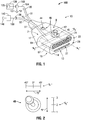
- FIG. 1 shows an electrosurgical system (shown generally as 100) according to an embodiment of the present disclosure that includes an energy-delivery device 10 including an ultrasound transducer array 67 and a microwave phased antenna array 61.
- Microwave phased antenna array 61 generally includes a plurality of radiating elements (e.g., "A 1 ", “A 2 ", “A 3 “, “A 4 " through “A N “ shown in FIG. 3 ) positioned to form a desired number of rows and columns.
- the radiating elements may be aperture (waveguide) or linear (dipole) antennas operating at S, L, or C band frequencies.
- the radiating elements may be spiral, dipole, slot, or any type of microstrip antenna, e.g., a patch antenna (also known as a rectangular microstrip antenna), and may be formed on a substrate, such as a dielectric sheet material, e.g., using conventional printed circuit board (PCB) fabrication techniques.
- a patch antenna also known as a rectangular microstrip antenna
- PCB printed circuit board
- Ultrasound transducer device 67 may be any suitable device capable of generating, transmitting and receiving ultrasound waves.
- Ultrasound transducer device 67 may include a one-dimensional or multi-dimensional array of transducer elements (not shown).
- Ultrasound transducer device 67 may be adapted for amplifying the reflected ultrasound signal received by the ultrasound transducer device 67.
- ultrasound transducer array 67 includes a plurality of transducer elements that are individually controllable and operable to form a two-dimensional array, e.g., suitable for scanning a volumetric region in three dimensions.
- Ultrasound transducer array 67 may be adapted to produce an image over a wide field of view, such as a sector scan image produced by repeatedly transmitting and receiving ultrasound energy in radial directions from the medical device 10. Ultrasound imaging may allow the clinician to observe the relationship between abnormal tissue structures, such as tumors, and normal tissue structures, such as vessels and tissue boundaries, during treatments.
- Energy-delivery device 10 includes a housing 15 generally defining a first axis "A 1 " - “A 1 ", e.g., a central longitudinal axis, and a second axis "A 2 " - “A 2 " disposed perpendicular to the first axis "A 1 " - “A 1 ".
- the housing 15 is formed from two housing halves (not shown). Each half of the housing 15 may include a series of mechanical interfacing components (not shown) configured to matingly engage with a corresponding series of mechanical interfaces (not shown) to align the two housing halves about the inner components and assemblies of the energy-delivery device 10.
- the housing 15 includes a body member 17 including a distal end 13.
- Body member 17 defines a tissue-contact surface 14 at the distal end 13, a top surface 12 including a proximal edge coupled to the tissue-contact surface 14, and an internal chamber 7 configured to contain the ultrasound transducer device 67 and the microwave phased antenna array 61 therein.
- Tissue-contact surface 14 may have any suitable configuration, e.g., a flat, planar or curved configuration, and may be disposed generally perpendicular to the top surface 12.
- Tissue-contact surface 14 generally includes one or more regions defining one or more electromagnetic windows through which electromagnetic signals are passed in use.
- the tissue-contact surface 14 includes a first region 28 defining an ultrasound transmissive window 27 and a second region 22 defining a microwave transmissive window 21.
- the first region 28 corresponds to a lower portion of the tissue-contact surface 14
- the second region 22 corresponds to an upper portion of the tissue-contact surface 14.
- Ultrasound transducer device 67 operations may involve directing ultrasound energy through the ultrasound transmissive window 27 and receiving ultrasound energy through the ultrasound transmissive window 27.
- Ultrasound transmissive window 27 and the microwave transmissive window 21 may be composed of low-loss dielectric materials. It will be appreciated that the ultrasound transmissive window 27 and the microwave transmissive window 21 may be disposed in any suitable relation to one another, such as one above (or below) the other, and may have any suitable shape, e.g., depending on the particular configuration of the ultrasound transducer device 67 and/or the microwave phased antenna array 61 housed within the body member 17.
- Body member 17, or portion thereof may be formed from metal, thermoplastic, e.g., polycarbonate, composites, e.g., plastic-metal or ceramic-metal composites, or other materials, and may be configured to be hand-holdable.
- the design and/or material of the ultrasound transmissive window 27 and the microwave transmissive window 21 may differ compared to one or more structural parts of the tissue-contact surface 14, e.g., to achieve desired electrical performance.
- the size and shape of the housing 15 may be varied from the configuration depicted in FIG. 1 .
- electrosurgical system 100 generally includes an electrosurgical power generating source 120, e.g., a microwave or RF electrosurgical generator, a user-interface 46 associated with the energy-delivery device 10, and a processor unit 150 communicatively coupled with the phased antenna array 61.
- User-interface 46 may be communicatively coupled with the processor unit 150 and/or other processor unit (not shown).
- Electrosurgical system 100 may include an ultrasonic imaging system 140 communicatively coupled with the ultrasound transducer array 67.
- Ultrasonic imaging system 140 may be connected to one or more display devices and/or screens 146 (e.g., LCD (liquid crystal display), plasma, OLED (organic light emitting diode), holographic, flat, and the like) for displaying output from the ultrasonic imaging system 140, which may allow clinicians to visualize the ablative process in real-time and/or near real-time.
- display devices and/or screens 146 e.g., LCD (liquid crystal display), plasma, OLED (organic light emitting diode), holographic, flat, and the like
- User-interface 46 may be adapted to cooperatively operate with the processor unit 150 and/or other processor (not shown) to enable the user to selectively-control one or more parameters of electromagnetic energy delivery into tissue by the medical device 10.
- User-interface 46 may be disposed on, or otherwise associated with, the housing 15, e.g., ergonomically located on the top surface 12 of the body member 17.
- the user-interface 46 includes a pointing device 45, e.g., a joystick, trackball, or the like, communicatively coupled to the processor unit 150.
- user-effected movement of the pointing device 45 is defined with respect to "X" and "Y" axes (schematically shown by double arrowheaded lines in FIG. 2 ), representative of indicative orientations of the pointing device 45.
- the axis “Y” may be oriented in a direction parallel to the first axis "A 1 " - “A 1 " of the housing 15, and the axis "X” may be oriented in a direction parallel to the second axis "A 2 " - “A 2 " of the housing 15.
- one or more parameters of electromagnetic energy delivery into tissue by the medical device 10 may be correlated to the indicative orientations of the pointing device 45.
- Pointing device 45 may be ergonomically located on the top surface 12 of the body member 17 such that the user can control the pointing device 45 easily with thumb, finger, or palm.
- the User-interface 46 may include voice input technology, including, for example, hardware and/or software incorporated in the processor unit 150, or a separate digital module connected to the processor unit 150.
- the voice input technology may include voice recognition, voice activation, voice rectification, and/or embedded speech.
- User-interface 46 may additionally, or alternatively, include a power on/off switch 44.
- the power on/off switch 44 may be disposed on, or otherwise associated with, the housing 15, e.g., ergonomically located on the top surface 12, and may have any suitable configuration, e.g., rotatable knobs, depressable buttons, toggle switches, slide switches, voice or sound actuated switches, or any other suitable device capable of turning off power to the medical device 10.
- the power on/off switch 44 may be implemented as a remotely operable device, such as a footswitch, a handswitch, or an orally-activated switch.
- User-interface 46 may additionally, or alternatively, include an indicator (not shown), such as an audible and/or visual indicator, e.g., an illuminated indicator (e.g., a single- or variably-colored LED indicator), to alert or signal the user that power is turned on/off.
- an indicator such as an audible and/or visual indicator, e.g., an illuminated indicator (e.g., a single- or variably-colored LED indicator), to alert or signal the user that power is turned on/off.
- User-interface 46 may be adapted to cooperatively operate with the processor unit 150 to enable the user to selectively-steer the focal point of energy delivery in tissue to various locations and/or to enable the user to the control the energy deposition pattern, e.g., an ablation field radiating into tissue.
- One or more electrical signals outputted from the user-interface 46, e.g., responsive to a user-effected movement of the pointing device 45, received by the processor unit 150 may be used to determine and set the phasing of radiating elements of the microwave phased antenna array 61, e.g., to allow the focal point of energy delivery in tissue to be varied in position in real-time and/or near real-time.
- Processor unit 150 may include any type of computing device, computational circuit, or any type of processor or processing circuit capable of executing a series of instructions that are stored in a memory, e.g., memory 151, associated with the processor unit 150.
- Processor unit 150 may be adapted to run an operating system platform and application programs.
- the processor unit 150 is illustrated as a standalone module in FIG. 1 , it is to be understood that the processor unit 150 may be integrated fully or partially into the electrosurgical power generating source 120, or other component of the electrosurgical system 100.
- Medical device 10 may be configured with a memory 51 disposed within the body member 17 and communicatively coupled with the processor unit 150 and/or communicatively coupled with an internal processor (not shown).
- Processor unit 150 may receive user inputs from the user-interface 46, such as an electric signal indicative of the position and/or a relative movement of the pointing device 45, e.g., a joystick or trackball, and/or other device communicatively coupled to the processor unit 150.
- data "D" (representative of a mapping of the indicative orientations of the pointing device 45 to settings for properly phasing the phased antenna array 61 to achieve desired radiation patterns) is stored in a suitable memory for use by the processor 150, e.g., to enable steering of the beam and/or the focal point of energy delivery in the desired direction and/or to the desired location in tissue.
- Data “D” may be stored in any suitable data structure, such as a look-up table or other data structure.
- Data “D” may be stored in a memory 51 (internal to medical device 10) and/or stored in a memory 151 (external to medical device 10).
- data “D” may be stored in a library (not shown) communicatively coupled to processor 150.
- library generally refers to any repository, databank, database, cache, storage unit and the like.
- Electrosurgical power generating source 120 may be any generator suitable for use with electrosurgical devices, and may be configured to provide various frequencies of electromagnetic energy. In some embodiments, the electrosurgical power generating source 120 is configured to provide microwave energy at an operational frequency from about 300 MHz to about 10 GHz.
- An example of an electrosurgical generator that delivers 915 MHz, which may be suitable for use as a source of electrosurgical energy, is commercially available under the trademark EVIDENTTM Microwave Ablation Generator offered by Covidien.
- Electrosurgical power generating source 120 may include a user-interface 125 in operable communication with processor unit 150. Electrosurgical power generating source 120 may include a database configured to store and retrieve energy applicator data, e.g., parameters associated with one or more energy-delivery devices. In use, the clinician may interact with the user-interface 125 to preview operational characteristics of an energy-delivery device, such as, for example, medical device 10.
- User-interface 125 may include a display device (not shown) adapted to visually display one or more user-interface elements. The display device may include touchscreen capability, e.g., the ability to receive user input through direct physical interaction with the display device, e.g., by contacting the display panel of the display device with a stylus or fingertip.
- Microwave phased antenna array 61 may be operably coupled to the processor unit 150 and/or the electrosurgical power generating source 120 by a cable connection or a wireless connection, e.g., a radiofrequency or infrared link.
- energy-delivery device 10 includes a first cable assembly 31 operably coupled to a first connector 35, which further operably connects the phased antenna array 61 via a first transmission line 104 to the processor unit 150.
- First cable assembly 31 may have a proximal end suitable for connection to the electrosurgical energy source 120.
- Energy-delivery device 10 may additionally, or alternatively, include a second cable assembly 32 operably coupled to a second connector 36, which further operably connects the ultrasound transducer device 61 via a second transmission line 109 to the ultrasonic imaging system 140.
- Second cable assembly 32 may have a proximal end suitable for connection to the ultrasonic imaging system 140.
- data acquired from the ultrasound transducer array 61 is outputted from the energy-delivery device 100 to the ultrasound imaging system 140, e.g., for processing to provide an image format suitable for display, and may be outputted from the imaging system 140 to one or more display devices 146, which may be used by the clinician to visualize the targeted region and/or the ablation isotherm volume in real-time or near real-time during a procedure.
- a bubble field or cloud of micro-fine bubbles may be generated in the targeted region, e.g., resulting from thermally-induced mass phase transition (e.g., liquid-gas phase transition), and may be visibly observable within the ultrasound imaging.
- Observation of the temporal evolution and spatial distribution of the bubble cloud generated in the target region may allow clinicians to better visualize and understand how to achieve more optimized results during thermal treatment of tissue, e.g., to allow clinicians to avoid ablating sensitive structures, such as large vessels, healthy organs or vital membrane barriers.
- Electrosurgical system 100 may include a coolant supply system (e.g., 350 shown in FIG. 3 ) coupled in fluid communication with one or more components of the medical device 10.
- the coolant supply system may be adapted to circulate coolant fluid (e.g., "F" shown in FIG. 3 ) into and out of an electromagnetic window (e.g., 390 shown in FIG. 3 ) disposed at the proximal end 13 of the housing 15.
- the medical device 10 is placed adjacent to tissue and microwave energy is supplied thereto.
- a clinician may pre-determine the length of time that microwave energy is to be applied.
- Application duration may depend on many factors such as tumor size and location and whether the tumor was a secondary or primary cancer.
- the duration of microwave energy application using the medical device 10 may depend on the progress of the heat distribution within the tissue area that is to be destroyed and/or the surrounding tissue. Treatment of certain tumors may involve probe repositioning during the ablation procedure, such as where the tumor is larger than the probe or has a shape that does not correspond with available probe geometry or radiation pattern.
- User-interface 46 may include indicia thereon representative of one or more user-selectable parameters of electromagnetic energy delivery into tissue by the medical device 10, e.g., a first scale “S 1 " and a second scale “S 2 ".
- the first scale “S 1 " includes indicia graduation marks and angle in degrees (e.g., 45°, 0°, 45°)
- the second scale “S 2 " includes indicia graduation marks and a series of consecutive positive integers (e.g., 1, 2, 3) corresponding to increasing levels of energy intensity indicative of energy intensity levels.
- the indicia may be etched, stamped, formed or the like, e.g., on the upper surface 12 and neighboring the pointing device 45. The design of the indicia may be varied from the configuration depicted in FIG. 2 .
- One or more parameters of electromagnetic energy delivery into tissue by the medical device 10 may be correlated to indicative orientations of the pointing device 45.
- User-effected movement of the pointing device 45 may be defined in terms of movement in a first direction (e.g., an X-axis direction) and movement in a second direction (e.g., a Y-axis direction) perpendicular to the first direction.
- Signals outputted from the pointing device 45 representative of indicative orientations of the pointing device 45 may be correlated to one or more parameters of electromagnetic energy delivery into tissue.
- user-effected movement of the pointing device 45 in a first direction e.g., an X-axis direction
- a second direction e.g., a Y-axis direction
- a third direction e.g., a Z-axis direction
- a predetermined phasing of the phased antenna array 61 to enable steering of the beam and/or steering of the focal point of energy delivery by the medical device 10 in the desired direction and/or to the desired location in tissue 'T'.
- medical device 10 is configured to adjust power parameters (e.g., voltage, power and/or current intensity) and/or the power verses impedance curve shape to affect the perceived output intensity, responsive to user-effected movement of the pointing device 45 in a first direction (e.g., an X-axis direction).
- power parameters e.g., voltage, power and/or current intensity
- the power verses impedance curve shape to affect the perceived output intensity, responsive to user-effected movement of the pointing device 45 in a first direction (e.g., an X-axis direction).
- Intensity settings may be preset and selected from a look-up table, e.g., based on a configuration of the radiating elements of the phased antenna array 61, desired surgical effect, surgical specialty and/or surgeon preference. The selection may be made automatically or selected manually by the user.
- the intensity values may be predetermined or adjusted by the user.
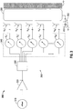
- FIG. 3 is schematic diagram of an embodiment of an energy-delivery system (shown generally as 300) that includes a signal source 310, a phased antenna array 360 coupled to the signal source 310, and a radiant electromagnetic energy transmissive structure 390 (also referred to herein as an "electromagnetic window") disposed at the proximal end of the phased antenna array 360.
- Signal source 310 is generally configured to provide microwave frequency output signals.
- Phased antenna array 360 includes a microwave amplifier unit 320 coupled to the signal source 310, a microwave power splitter 330 coupled to the microwave amplifier unit 320, a controller 340 coupled to the microwave power splitter 330, and a plurality of radiating elements "A 1 ", "A 2 ", “A 3 ", “A 4 " through “A N “ coupled to the controller 340.
- Microwave amplifier unit 320 may have any suitable input power and output power.
- Power splitter 330 may be implemented by a variety of components, including without limitation, coplanar striplines, coplanar waveguides, Wilkinson power dividers, and/or other suitable power dividers. In some embodiments, the power splitter 330 may be implemented by any suitable power divider that provides an equal or unequal power split at its output ports while substantially maintaining a predetermined phase relationship.
- Controller 340 generally includes a plurality of phase shifters “S 1 ", “S 2 “, “S 3 “, “S 4 “ through “S N “. Controller 340 may include a number of processor units (not shown) coupled to the phase shifters “S 1 “, “S 2 “, “S 3 “, “S 4 “ through “S N “ for controlling output of one or more of the phase shifters “S 1 " through “S N “ to provide a desired phase relationship of electrical signals in each channel of the phased antenna array 360.
- the processing units may include multiple processors and/or multicore CPUs and may include any type of processor capable of executing software, such as a microprocessor, digital signal processor, microcontroller, or the like.
- Energy-delivery system 300 includes an electromagnetic window 390 disposed between the phased antenna array 360 and tissue "T".
- Electromagnetic window 390 may include a water bolus, or other dielectric material.
- the electromagnetic window 390 is coupled in fluid communication with a coolant supply system 350 including a coolant source 355.
- Coolant source 355 may be any suitable housing containing a reservoir of coolant fluid "F", and may maintain coolant fluid "F” at a predetermined temperature.
- the coolant source 355 may include a cooling unit (not shown) capable of cooling the returning coolant fluid "F” from the electromagnetic window 390.
- Coolant fluid "F” may be any suitable fluid that can be used for cooling or buffering the electromagnetic window 390, e.g., deionized water, or other suitable cooling medium. Coolant fluid "F” may have dielectric properties and may provide dielectric impedance buffering for the phased antenna array 360.
- liquids including, but not limited to, water, saline, perfluorocarbon, such as the commercially available Fluorinert ® perfluorocarbon liquid offered by Minnesota Mining and Manufacturing Company (3M), liquid chlorodifluoromethane, etc.
- gases such as nitrous oxide, nitrogen, carbon dioxide, etc.
- a combination of liquids and/or gases including, for example, those mentioned above, may be utilized as the coolant fluid "F".
- FIGS. 4 through 7 show the medical device 10 positioned for delivery of electromagnetic energy into tissue "T' shown with the pointing device 45 positioned in varied indicative orientations and shown with diagrammatic representations of radiation patterns of electromagnetic energy delivered into tissue by the medical device 10 responsive to the indicative orientations of the pointing device 45.
- the indicative orientations of the pointing device 45 and the radiation patterns of electromagnetic energy are provided for illustrative purposes only, and that medical device 10 embodiments of the present disclosure may be utilized with many different indicative orientations of the pointing device 45 and many different radiation patterns.
- FIG. 4 shows the tissue-contact surface 14 of the medical device 10 disposed adjacent to tissue "T" during a procedure, e.g., an ablation procedure, wherein the pointing device 45 is positioned in a first indicative orientation "I 1 ".
- the first indicative orientation "I 1 " may correlate with a 30° beam angle and an intensity level "1", e.g., low-intensity level.
- FIG. 4 shows a diagrammatic representation of a radiation pattern "P 1 " of electromagnetic energy delivered into tissue "T" by the medical device 10 responsive to the first indicative orientation "I 1 " of the pointing device 45 in accordance with an embodiment of the present disclosure.
- FIG. 5 shows the tissue-contact surface 14 of the medical device 10 disposed adjacent to tissue "T" during a procedure wherein the pointing device 45 is positioned in a second indicative orientation "I 2 ".
- the second indicative orientation "I 2 " may correlate with a 0° beam angle and an intensity level "2", e.g., medium-intensity level.
- FIG. 5 shows a diagrammatic representation of a radiation pattern "P 2 " of electromagnetic energy delivered into tissue "T" by the medical device responsive to the second indicative orientation "I 2 " of the pointing device 45 in accordance with an embodiment of the present disclosure.
- FIG. 6 shows the tissue-contact surface 14 of the medical device 10 disposed adjacent to tissue "T" during a procedure wherein the pointing device 45 is positioned in a third indicative orientation "I 3 ".
- the third indicative orientation "I 3 " may correlate with a 0° beam angle and an intensity level "3", e.g., high-intensity level.
- FIG. 6 shows a diagrammatic representation of a radiation pattern "P 3 " of electromagnetic energy delivered into tissue "T" by the medical device responsive to the third indicative orientation "I 3 " of the pointing device 45 in accordance with an embodiment of the present disclosure.
- FIG. 7 shows the tissue-contact surface 14 of the medical device 10 disposed adjacent to tissue "T" during a procedure wherein the pointing device 45 is positioned in a fourth indicative orientation "I 4 ".
- the fourth indicative orientation "I 4 " may correlate with a -30° beam angle and an intensity level "1", e.g., low-intensity level.
- FIG. 7 shows a diagrammatic representation of a radiation pattern "P 4 " of electromagnetic energy delivered into tissue "T" by the medical device 10 responsive to the fourth indicative orientation "I 4 " of the pointing device 45 in accordance with an embodiment of the present disclosure.
- FIG. 8 is a schematic diagram of an embodiment of a control system 800 according to the present disclosure that is communicatively coupled with an on/off button 810 and configured to utilize a joystick position signal 820 indicative of intensity and angle of beam.
- the control system 800 utilizes the joystick position signal 820 to determine whether to adjust antenna and/or amplifier gain 830 and/or to determine the phasing of the radiating elements (1 through N) of a phased antenna array 861, e.g., to allow the focal point of energy delivery in tissue to be varied in position in real-time and/or near real-time.
- Control system 800 is configured such that when the on/off button 810 is in the "ON” state, adjustment of antenna and/or amplifier gain 830 is permitted, and when the on/off button 810 is in the "OFF” state, adjustment of antenna and/or amplifier gain 830 is not permitted.
- Joystick position signal 820 may be used in conjunction with a lookup table 840 to enable selective steering of the radiated beam of the phased antenna array 861.
- Lookup table 840 includes data representative of a mapping of the joystick positions to the phasing of the phased antenna array 861. As schematically-illustrated in FIG. 8 , the control system 800 utilizes the lookup table 840 to determine the phasing of the radiating elements (1 through N) of the phased antenna array 861.
- the above-described energy-delivery devices including an ultrasound transducer array and a phased antenna array are capable of directing energy into tissue, and may be suitable for use in a variety of procedures and operations.
- the presently-disclosed energy-delivery device including an ultrasound transducer array and a phased antenna array may be implemented using electromagnetic radiation at microwave frequencies, RF frequencies or at other frequencies.
- the above-described energy-delivery device including an ultrasound transducer array and a phased antenna array are adapted to be hand-holdable and include an ergonomically located user-interface.
- the above-described electrosurgical systems provide clinicians the ability to visualize a tissue region during energy delivery into the tissue region.
- data acquired by the ultrasound transducer array may be outputted from the above-described energy-delivery device to an ultrasound imaging system, and may be outputted from the imaging system to one or more display devices and/or screens, which may be used by the clinician to visualize the targeted region in real-time and/or near real-time.
Landscapes
- Health & Medical Sciences (AREA)
- Life Sciences & Earth Sciences (AREA)
- Surgery (AREA)
- Public Health (AREA)
- Veterinary Medicine (AREA)
- Nuclear Medicine, Radiotherapy & Molecular Imaging (AREA)
- Physics & Mathematics (AREA)
- Engineering & Computer Science (AREA)
- Biomedical Technology (AREA)
- Heart & Thoracic Surgery (AREA)
- Medical Informatics (AREA)
- Molecular Biology (AREA)
- General Health & Medical Sciences (AREA)
- Animal Behavior & Ethology (AREA)
- Biophysics (AREA)
- Radiology & Medical Imaging (AREA)
- Pathology (AREA)
- Electromagnetism (AREA)
- Otolaryngology (AREA)
- Surgical Instruments (AREA)
Applications Claiming Priority (1)
| Application Number | Priority Date | Filing Date | Title |
|---|---|---|---|
| US13/029,521 US8376948B2 (en) | 2011-02-17 | 2011-02-17 | Energy-delivery device including ultrasound transducer array and phased antenna array |
Publications (2)
| Publication Number | Publication Date |
|---|---|
| EP2489321A1 true EP2489321A1 (de) | 2012-08-22 |
| EP2489321B1 EP2489321B1 (de) | 2014-04-09 |
Family
ID=45655028
Family Applications (1)
| Application Number | Title | Priority Date | Filing Date |
|---|---|---|---|
| EP12000984.0A Not-in-force EP2489321B1 (de) | 2011-02-17 | 2012-02-15 | Energieabgabevorrichtung mit einer Ultraschallwandleranordnung und einer phasengesteuerten Gruppenantenne |
Country Status (5)
| Country | Link |
|---|---|
| US (1) | US8376948B2 (de) |
| EP (1) | EP2489321B1 (de) |
| JP (1) | JP6104508B2 (de) |
| AU (1) | AU2012200877B2 (de) |
| CA (1) | CA2768158C (de) |
Cited By (1)
| Publication number | Priority date | Publication date | Assignee | Title |
|---|---|---|---|---|
| US9469241B2 (en) | 2012-09-11 | 2016-10-18 | Zedel S.A. | Electric lamp having an automatic light regulation |
Families Citing this family (12)
| Publication number | Priority date | Publication date | Assignee | Title |
|---|---|---|---|---|
| US8394092B2 (en) | 2009-11-17 | 2013-03-12 | Vivant Medical, Inc. | Electromagnetic energy delivery devices including an energy applicator array and electrosurgical systems including same |
| US8409188B2 (en) | 2010-03-26 | 2013-04-02 | Covidien Lp | Ablation devices with adjustable radiating section lengths, electrosurgical systems including same, and methods of adjusting ablation fields using same |
| US9724010B2 (en) | 2010-07-08 | 2017-08-08 | Emtensor Gmbh | Systems and methods of 4D electromagnetic tomographic (EMT) differential (dynamic) fused imaging |
| US10335230B2 (en) | 2011-03-09 | 2019-07-02 | Covidien Lp | Systems for thermal-feedback-controlled rate of fluid flow to fluid-cooled antenna assembly and methods of directing energy to tissue using same |
| US8888771B2 (en) | 2011-07-15 | 2014-11-18 | Covidien Lp | Clip-over disposable assembly for use with hemostat-style surgical instrument and methods of manufacturing same |
| US9119648B2 (en) | 2012-01-06 | 2015-09-01 | Covidien Lp | System and method for treating tissue using an expandable antenna |
| US9364278B2 (en) | 2012-04-30 | 2016-06-14 | Covidien Lp | Limited reuse ablation needles and ablation devices for use therewith |
| CA2936145C (en) | 2012-11-21 | 2021-06-15 | Emtensor Gmbh | Electromagnetic tomography solutions for scanning head |
| US20140275944A1 (en) | 2013-03-15 | 2014-09-18 | Emtensor Gmbh | Handheld electromagnetic field-based bio-sensing and bio-imaging system |
| US9072449B2 (en) * | 2013-03-15 | 2015-07-07 | Emtensor Gmbh | Wearable/man-portable electromagnetic tomographic imaging |
| WO2017066731A1 (en) | 2015-10-16 | 2017-04-20 | Emtensor Gmbh | Electromagnetic interference pattern recognition tomography |
| ES2957552T3 (es) | 2016-11-23 | 2024-01-22 | Emtensor Gmbh | Uso de campo electromagnético para imágenes tomográficas de la cabeza |
Citations (4)
| Publication number | Priority date | Publication date | Assignee | Title |
|---|---|---|---|---|
| US20070016032A1 (en) * | 2005-04-05 | 2007-01-18 | Gerard Aknine | Microwave devices for treating biological samples and tissue and methods for imaging |
| WO2007134256A2 (en) * | 2006-05-11 | 2007-11-22 | Reliant Technologies, Inc. | Apparatus and method for ablation-related dermatological treatment of selected targets |
| US20080125772A1 (en) * | 2004-09-10 | 2008-05-29 | Minnow Medical, Inc | Tuned RF energy and electrical tissue characterization for selective treatment of target tissues |
| US20090221999A1 (en) * | 2008-02-29 | 2009-09-03 | Ramin Shahidi | Thermal Ablation Design and Planning Methods |
Family Cites Families (123)
| Publication number | Priority date | Publication date | Assignee | Title |
|---|---|---|---|---|
| DE390937C (de) | 1922-10-13 | 1924-03-03 | Adolf Erb | Vorrichtung zur Innenbeheizung von Wannenoefen zum Haerten, Anlassen, Gluehen, Vergueten und Schmelzen |
| DE1099658B (de) | 1959-04-29 | 1961-02-16 | Siemens Reiniger Werke Ag | Selbsttaetige Einschaltvorrichtung fuer Hochfrequenzchirurgiegeraete |
| FR1275415A (fr) | 1960-09-26 | 1961-11-10 | Dispositif détecteur de perturbations pour installations électriques, notamment d'électrochirurgie | |
| DE1139927B (de) | 1961-01-03 | 1962-11-22 | Friedrich Laber | Hochfrequenz-Chirurgiegeraet |
| DE1149832C2 (de) | 1961-02-25 | 1977-10-13 | Siemens AG, 1000 Berlin und 8000 München | Hochfrequenz-chirurgieapparat |
| FR1347865A (fr) | 1962-11-22 | 1964-01-04 | Perfectionnements aux appareils de diathermo-coagulation | |
| DE1439302B2 (de) | 1963-10-26 | 1971-05-19 | Siemens AG, 1000 Berlin u 8000 München | Hochfrequenz Chirurgiegerat |
| SU401367A1 (ru) | 1971-10-05 | 1973-10-12 | Тернопольский государственный медицинский институт | Биактивный электрохирургическнп инструмент |
| FR2235669A1 (en) | 1973-07-07 | 1975-01-31 | Lunacek Boris | Gynaecological sterilisation instrument - has hollow electrode protruding from the end of a curved ended tube |
| GB1480736A (en) | 1973-08-23 | 1977-07-20 | Matburn Ltd | Electrodiathermy apparatus |
| FR2251864A1 (en) | 1973-11-21 | 1975-06-13 | Termiflex Corp | Portable input and output unit for connection to a data processor - is basically a calculator with transmitter and receiver |
| DE2407559C3 (de) | 1974-02-16 | 1982-01-21 | Dornier System Gmbh, 7990 Friedrichshafen | Wärmesonde |
| DE2415263A1 (de) | 1974-03-29 | 1975-10-02 | Aesculap Werke Ag | Chirurgische hf-koagulationssonde |
| DE2429021C2 (de) | 1974-06-18 | 1983-12-08 | Erbe Elektromedizin GmbH, 7400 Tübingen | Fernschalteinrichtung für ein HF-Chirurgiegerät |
| FR2276027A1 (fr) | 1974-06-25 | 1976-01-23 | Medical Plastics Inc | Raccordement electrique pour electrode plane |
| DE2460481A1 (de) | 1974-12-20 | 1976-06-24 | Delma Elektro Med App | Elektrodenhandgriff zur handfernschaltung eines hochfrequenz-chirurgiegeraets |
| US4237887A (en) | 1975-01-23 | 1980-12-09 | Valleylab, Inc. | Electrosurgical device |
| DE2504280C3 (de) | 1975-02-01 | 1980-08-28 | Hans Heinrich Prof. Dr. 8035 Gauting Meinke | Vorrichtung zum Schneiden und/oder Koagulieren menschlichen Gewebes mit Hochfrequenzstrom |
| CA1064581A (en) | 1975-06-02 | 1979-10-16 | Stephen W. Andrews | Pulse control circuit and method for electrosurgical units |
| FR2315286A2 (fr) | 1975-06-26 | 1977-01-21 | Lamidey Marcel | Pince a dissequer, hemostatique, haute frequence |
| DE2540968C2 (de) | 1975-09-13 | 1982-12-30 | Erbe Elektromedizin GmbH, 7400 Tübingen | Einrichtung zum Einschalten des Koagulationsstroms einer bipolaren Koagulationspinzette |
| FR2390968A1 (fr) | 1977-05-16 | 1978-12-15 | Skovajsa Joseph | Dispositif de traitement local d'un patient, notamment pour acupuncture ou auriculotherapie |
| SU727201A2 (ru) | 1977-11-02 | 1980-04-15 | Киевский Научно-Исследовательский Институт Нейрохирургии | Электрохирургический аппарат |
| DE2803275C3 (de) | 1978-01-26 | 1980-09-25 | Aesculap-Werke Ag Vormals Jetter & Scheerer, 7200 Tuttlingen | Fernschalteinrichtung zum Schalten eines monopolaren HF-Chirurgiegerätes |
| DE2823291A1 (de) | 1978-05-27 | 1979-11-29 | Rainer Ing Grad Koch | Schaltung zur automatischen einschaltung des hochfrequenzstromes von hochfrequenz-koagulationsgeraeten |
| DE2946728A1 (de) | 1979-11-20 | 1981-05-27 | Erbe Elektromedizin GmbH & Co KG, 7400 Tübingen | Hochfrequenz-chirurgiegeraet |
| USD263020S (en) | 1980-01-22 | 1982-02-16 | Rau Iii David M | Retractable knife |
| USD266842S (en) | 1980-06-27 | 1982-11-09 | Villers Mark W | Phonograph record spacer |
| USD278306S (en) | 1980-06-30 | 1985-04-09 | Mcintosh Lois A | Microwave oven rack |
| JPS5778844A (en) | 1980-11-04 | 1982-05-17 | Kogyo Gijutsuin | Lasre knife |
| DE3045996A1 (de) | 1980-12-05 | 1982-07-08 | Medic Eschmann Handelsgesellschaft für medizinische Instrumente mbH, 2000 Hamburg | Elektro-chirurgiegeraet |
| FR2502935B1 (fr) | 1981-03-31 | 1985-10-04 | Dolley Roger | Procede et dispositif de controle de la coagulation de tissus a l'aide d'un courant a haute frequence |
| DE3120102A1 (de) | 1981-05-20 | 1982-12-09 | F.L. Fischer GmbH & Co, 7800 Freiburg | Anordnung zur hochfrequenzkoagulation von eiweiss fuer chirurgische zwecke |
| JPS5846949A (ja) * | 1981-09-14 | 1983-03-18 | アロカ株式会社 | 電子走査型超音波探触子 |
| FR2517953A1 (fr) | 1981-12-10 | 1983-06-17 | Alvar Electronic | Appareil diaphanometre et son procede d'utilisation |
| FR2573301B3 (fr) | 1984-11-16 | 1987-04-30 | Lamidey Gilles | Pince chirurgicale et son appareillage de commande et de controle |
| DE3510586A1 (de) | 1985-03-23 | 1986-10-02 | Erbe Elektromedizin GmbH, 7400 Tübingen | Kontrolleinrichtung fuer ein hochfrequenz-chirurgiegeraet |
| USD295893S (en) | 1985-09-25 | 1988-05-24 | Acme United Corporation | Disposable surgical clamp |
| USD295894S (en) | 1985-09-26 | 1988-05-24 | Acme United Corporation | Disposable surgical scissors |
| DE3604823C2 (de) | 1986-02-15 | 1995-06-01 | Lindenmeier Heinz | Hochfrequenzgenerator mit automatischer Leistungsregelung für die Hochfrequenzchirurgie |
| US4700716A (en) | 1986-02-27 | 1987-10-20 | Kasevich Associates, Inc. | Collinear antenna array applicator |
| EP0246350A1 (de) | 1986-05-23 | 1987-11-25 | Erbe Elektromedizin GmbH. | Koagulationselektrode |
| DE3711511C1 (de) | 1987-04-04 | 1988-06-30 | Hartmann & Braun Ag | Verfahren zur Bestimmung der Gaskonzentrationen in einem Gasgemisch und Sensor zur Messung der Waermeleitfaehigkeit |
| DE8712328U1 (de) | 1987-09-11 | 1988-02-18 | Jakoubek, Franz, 7201 Emmingen-Liptingen | Endoskopiezange |
| DE3904558C2 (de) | 1989-02-15 | 1997-09-18 | Lindenmeier Heinz | Automatisch leistungsgeregelter Hochfrequenzgenerator für die Hochfrequenz-Chirurgie |
| DE3942998C2 (de) | 1989-12-27 | 1998-11-26 | Delma Elektro Med App | Elektrochirurgisches Hochfrequenzgerät |
| DE4122050C2 (de) | 1991-07-03 | 1996-05-30 | Gore W L & Ass Gmbh | Antennenanordnung mit Zuleitung zur medizinischen Wärmeapplikation in Körperhohlräumen |
| DE4238263A1 (en) | 1991-11-15 | 1993-05-19 | Minnesota Mining & Mfg | Adhesive comprising hydrogel and crosslinked polyvinyl:lactam - is used in electrodes for biomedical application providing low impedance and good mechanical properties when water and/or moisture is absorbed from skin |
| DE4205213A1 (de) | 1992-02-20 | 1993-08-26 | Delma Elektro Med App | Hochfrequenzchirurgiegeraet |
| FR2687786B1 (fr) | 1992-02-26 | 1994-05-06 | Pechiney Recherche | Mesure de la resistivite electrique et de la conductivite thermique a haute temperature de produits refractaires. |
| USD354218S (en) | 1992-10-01 | 1995-01-10 | Fiberslab Pty Limited | Spacer for use in concrete construction |
| JPH06197908A (ja) * | 1993-01-06 | 1994-07-19 | Toshiba Corp | 衝撃波治療装置 |
| DE4303882C2 (de) | 1993-02-10 | 1995-02-09 | Kernforschungsz Karlsruhe | Kombinationsinstrument zum Trennen und Koagulieren für die minimal invasive Chirurgie |
| FR2711066B1 (fr) | 1993-10-15 | 1995-12-01 | Sadis Bruker Spectrospin | Antenne pour le chauffage de tissus par micro-ondes et sonde comportant une ou plusieurs de ces antennes. |
| DE4339049C2 (de) | 1993-11-16 | 2001-06-28 | Erbe Elektromedizin | Einrichtung zur Konfiguration chirurgischer Systeme |
| CN1079269C (zh) | 1993-11-17 | 2002-02-20 | 刘中一 | 多频率微波治疗仪 |
| US6575969B1 (en) | 1995-05-04 | 2003-06-10 | Sherwood Services Ag | Cool-tip radiofrequency thermosurgery electrode system for tumor ablation |
| US5769879A (en) * | 1995-06-07 | 1998-06-23 | Medical Contouring Corporation | Microwave applicator and method of operation |
| US5843144A (en) * | 1995-06-26 | 1998-12-01 | Urologix, Inc. | Method for treating benign prostatic hyperplasia with thermal therapy |
| DE19608716C1 (de) | 1996-03-06 | 1997-04-17 | Aesculap Ag | Bipolares chirurgisches Faßinstrument |
| DE29616210U1 (de) | 1996-09-18 | 1996-11-14 | Olympus Winter & Ibe Gmbh, 22045 Hamburg | Handhabe für chirurgische Instrumente |
| DE19643127A1 (de) | 1996-10-18 | 1998-04-23 | Berchtold Gmbh & Co Geb | Hochfrequenzchirurgiegerät und Verfahren zu dessen Betrieb |
| US5923475A (en) | 1996-11-27 | 1999-07-13 | Eastman Kodak Company | Laser printer using a fly's eye integrator |
| DE19717411A1 (de) | 1997-04-25 | 1998-11-05 | Aesculap Ag & Co Kg | Verfahren und Vorrichtung zur Überwachung der thermischen Belastung des Gewebes eines Patienten |
| EP0882955B1 (de) | 1997-06-06 | 2005-04-06 | Endress + Hauser GmbH + Co. KG | Mit Mikrowellen arbeitendes Füllstandsmessgerät |
| US6104959A (en) | 1997-07-31 | 2000-08-15 | Microwave Medical Corp. | Method and apparatus for treating subcutaneous histological features |
| DE69834644T2 (de) | 1997-08-13 | 2007-05-10 | Solarant Medical, Inc., Livermore | Nichtinvasive geräte und systeme zum schrumpfen von geweben |
| DE19751108A1 (de) | 1997-11-18 | 1999-05-20 | Beger Frank Michael Dipl Desig | Elektrochirurgisches Operationswerkzeug |
| DE19801173C1 (de) | 1998-01-15 | 1999-07-15 | Kendall Med Erzeugnisse Gmbh | Klemmverbinder für Filmelektroden |
| DE19848540A1 (de) | 1998-10-21 | 2000-05-25 | Reinhard Kalfhaus | Schaltungsanordnung und Verfahren zum Betreiben eines Wechselrichters |
| USD449886S1 (en) | 1998-10-23 | 2001-10-30 | Sherwood Services Ag | Forceps with disposable electrode |
| USD424694S (en) | 1998-10-23 | 2000-05-09 | Sherwood Services Ag | Forceps |
| USD425201S (en) | 1998-10-23 | 2000-05-16 | Sherwood Services Ag | Disposable electrode assembly |
| US6097985A (en) | 1999-02-09 | 2000-08-01 | Kai Technologies, Inc. | Microwave systems for medical hyperthermia, thermotherapy and diagnosis |
| US6181970B1 (en) | 1999-02-09 | 2001-01-30 | Kai Technologies, Inc. | Microwave devices for medical hyperthermia, thermotherapy and diagnosis |
| USD424693S (en) | 1999-04-08 | 2000-05-09 | Pruter Rick L | Needle guide for attachment to an ultrasound transducer probe |
| US7226446B1 (en) | 1999-05-04 | 2007-06-05 | Dinesh Mody | Surgical microwave ablation assembly |
| GB9911956D0 (en) | 1999-05-21 | 1999-07-21 | Gyrus Medical Ltd | Electrosurgery system and method |
| GB9911954D0 (en) | 1999-05-21 | 1999-07-21 | Gyrus Medical Ltd | Electrosurgery system and instrument |
| GB9912627D0 (en) | 1999-05-28 | 1999-07-28 | Gyrus Medical Ltd | An electrosurgical instrument |
| GB9912625D0 (en) | 1999-05-28 | 1999-07-28 | Gyrus Medical Ltd | An electrosurgical generator and system |
| GB9913652D0 (en) | 1999-06-11 | 1999-08-11 | Gyrus Medical Ltd | An electrosurgical generator |
| US6542767B1 (en) | 1999-11-09 | 2003-04-01 | Biotex, Inc. | Method and system for controlling heat delivery to a target |
| JP2001231870A (ja) | 2000-02-23 | 2001-08-28 | Olympus Optical Co Ltd | 加温治療装置 |
| US6944504B1 (en) | 2000-02-23 | 2005-09-13 | The United States Of America As Represented By The Administrator Of The National Aeronautics And Space Administration | Microwave medical treatment apparatus and method |
| JP3875841B2 (ja) * | 2000-03-28 | 2007-01-31 | アロカ株式会社 | 医療システム |
| DE10027727C1 (de) | 2000-06-03 | 2001-12-06 | Aesculap Ag & Co Kg | Scheren- oder zangenförmiges chirurgisches Instrument |
| US20020087151A1 (en) | 2000-12-29 | 2002-07-04 | Afx, Inc. | Tissue ablation apparatus with a sliding ablation instrument and method |
| US20020165529A1 (en) | 2001-04-05 | 2002-11-07 | Danek Christopher James | Method and apparatus for non-invasive energy delivery |
| USD457958S1 (en) | 2001-04-06 | 2002-05-28 | Sherwood Services Ag | Vessel sealer and divider |
| USD457959S1 (en) | 2001-04-06 | 2002-05-28 | Sherwood Services Ag | Vessel sealer |
| DE10224154A1 (de) | 2002-05-27 | 2003-12-18 | Celon Ag Medical Instruments | Vorrichtung zum elektrochirurgischen Veröden von Körpergewebe |
| AU2003302229A1 (en) | 2002-09-27 | 2004-06-30 | The Trustees Of Dartmouth College | Imaging by magnetic resonance adsorption, elastography and tomography |
| JP4192545B2 (ja) * | 2002-09-27 | 2008-12-10 | 株式会社日立メディコ | 超音波診断装置 |
| USD487039S1 (en) | 2002-11-27 | 2004-02-24 | Robert Bosch Corporation | Spacer |
| DE10310765A1 (de) | 2003-03-12 | 2004-09-30 | Dornier Medtech Systems Gmbh | Sonde und Vorrichtung für eine Thermotherapie |
| USD499181S1 (en) | 2003-05-15 | 2004-11-30 | Sherwood Services Ag | Handle for a vessel sealer and divider |
| USD496997S1 (en) | 2003-05-15 | 2004-10-05 | Sherwood Services Ag | Vessel sealer and divider |
| US6957108B2 (en) | 2003-06-02 | 2005-10-18 | Bsd Medical Corporation | Invasive microwave antenna array for hyperthermia and brachytherapy |
| DE10328514B3 (de) | 2003-06-20 | 2005-03-03 | Aesculap Ag & Co. Kg | Chirurgisches Instrument |
| FR2862813B1 (fr) | 2003-11-20 | 2006-06-02 | Pellenc Sa | Procede de chargement equilibre d'une batterie lithium-ion ou lithium polymere |
| FR2864439B1 (fr) | 2003-12-30 | 2010-12-03 | Image Guided Therapy | Dispositif de traitement d'un volume de tissu biologique par hyperthermie localisee |
| USD541938S1 (en) | 2004-04-09 | 2007-05-01 | Sherwood Services Ag | Open vessel sealer with mechanical cutter |
| DE102004022206B4 (de) | 2004-05-04 | 2006-05-11 | Bundesrepublik Deutschland, vertr. d. d. Bundesministerium für Wirtschaft und Arbeit, dieses vertr. d. d. Präsidenten der Physikalisch-Technischen Bundesanstalt | Sensor und Sensoranordnung zur Messung der Wärmeleitfähigkeit einer Probe |
| USD533942S1 (en) | 2004-06-30 | 2006-12-19 | Sherwood Services Ag | Open vessel sealer with mechanical cutter |
| USD541418S1 (en) | 2004-10-06 | 2007-04-24 | Sherwood Services Ag | Lung sealing device |
| USD531311S1 (en) | 2004-10-06 | 2006-10-31 | Sherwood Services Ag | Pistol grip style elongated dissecting and dividing instrument |
| USD535027S1 (en) | 2004-10-06 | 2007-01-09 | Sherwood Services Ag | Low profile vessel sealing and cutting mechanism |
| USD525361S1 (en) | 2004-10-06 | 2006-07-18 | Sherwood Services Ag | Hemostat style elongated dissecting and dividing instrument |
| USD564662S1 (en) | 2004-10-13 | 2008-03-18 | Sherwood Services Ag | Hourglass-shaped knife for electrosurgical forceps |
| US7452357B2 (en) * | 2004-10-22 | 2008-11-18 | Ethicon Endo-Surgery, Inc. | System and method for planning treatment of tissue |
| USD576932S1 (en) | 2005-03-01 | 2008-09-16 | Robert Bosch Gmbh | Spacer |
| US20060265034A1 (en) | 2005-04-05 | 2006-11-23 | Ams Medical Sa | Microwave devices for treating biological samples and tissue and methods for using same |
| DE202005015147U1 (de) | 2005-09-26 | 2006-02-09 | Health & Life Co., Ltd., Chung-Ho | Biosensor-Teststreifen mit Identifizierfunktion |
| EP1998698B1 (de) | 2006-03-24 | 2020-12-23 | Neuwave Medical, Inc. | Wärmeübertragungsfähige übertragungsleitung |
| US20070276240A1 (en) * | 2006-05-02 | 2007-11-29 | Rosner S J | System and method for imaging a target medium using acoustic and electromagnetic energies |
| JP4618241B2 (ja) | 2006-12-13 | 2011-01-26 | 株式会社村田製作所 | 同軸プローブ装置 |
| USD606203S1 (en) | 2008-07-04 | 2009-12-15 | Cambridge Temperature Concepts, Ltd. | Hand-held device |
| USD594736S1 (en) | 2008-08-13 | 2009-06-23 | Saint-Gobain Ceramics & Plastics, Inc. | Spacer support |
| WO2010035831A1 (ja) | 2008-09-29 | 2010-04-01 | 京セラ株式会社 | 切削インサート、切削工具、およびそれらを用いる切削方法 |
| USD594737S1 (en) | 2008-10-28 | 2009-06-23 | Mmi Management Services Lp | Rebar chair |
| USD634010S1 (en) | 2009-08-05 | 2011-03-08 | Vivant Medical, Inc. | Medical device indicator guide |
| USD613412S1 (en) | 2009-08-06 | 2010-04-06 | Vivant Medical, Inc. | Vented microwave spacer |
-
2011
- 2011-02-17 US US13/029,521 patent/US8376948B2/en not_active Expired - Fee Related
-
2012
- 2012-02-14 JP JP2012029390A patent/JP6104508B2/ja not_active Expired - Fee Related
- 2012-02-15 CA CA2768158A patent/CA2768158C/en active Active
- 2012-02-15 AU AU2012200877A patent/AU2012200877B2/en not_active Ceased
- 2012-02-15 EP EP12000984.0A patent/EP2489321B1/de not_active Not-in-force
Patent Citations (4)
| Publication number | Priority date | Publication date | Assignee | Title |
|---|---|---|---|---|
| US20080125772A1 (en) * | 2004-09-10 | 2008-05-29 | Minnow Medical, Inc | Tuned RF energy and electrical tissue characterization for selective treatment of target tissues |
| US20070016032A1 (en) * | 2005-04-05 | 2007-01-18 | Gerard Aknine | Microwave devices for treating biological samples and tissue and methods for imaging |
| WO2007134256A2 (en) * | 2006-05-11 | 2007-11-22 | Reliant Technologies, Inc. | Apparatus and method for ablation-related dermatological treatment of selected targets |
| US20090221999A1 (en) * | 2008-02-29 | 2009-09-03 | Ramin Shahidi | Thermal Ablation Design and Planning Methods |
Cited By (1)
| Publication number | Priority date | Publication date | Assignee | Title |
|---|---|---|---|---|
| US9469241B2 (en) | 2012-09-11 | 2016-10-18 | Zedel S.A. | Electric lamp having an automatic light regulation |
Also Published As
| Publication number | Publication date |
|---|---|
| CA2768158A1 (en) | 2012-08-17 |
| EP2489321B1 (de) | 2014-04-09 |
| US20120215103A1 (en) | 2012-08-23 |
| JP2012170822A (ja) | 2012-09-10 |
| AU2012200877B2 (en) | 2014-05-01 |
| JP6104508B2 (ja) | 2017-03-29 |
| AU2012200877A1 (en) | 2012-09-06 |
| US8376948B2 (en) | 2013-02-19 |
| CA2768158C (en) | 2018-08-14 |
Similar Documents
| Publication | Publication Date | Title |
|---|---|---|
| US9192441B2 (en) | Energy-delivery device including ultrasound transducer array and phased antenna array, and methods of adjusting an ablation field radiating into tissue using same | |
| US8376948B2 (en) | Energy-delivery device including ultrasound transducer array and phased antenna array | |
| EP2345454B1 (de) | Ablationsvorrichtung mit Benutzerschnittstelle am Vorrichtungsgriff und System mit der Ablationsvorrichtung | |
| US8394092B2 (en) | Electromagnetic energy delivery devices including an energy applicator array and electrosurgical systems including same | |
| US8491579B2 (en) | Electrosurgical devices with choke shorted to biological tissue | |
| US8690869B2 (en) | Electrosurgical devices with directional radiation pattern | |
| US9370392B2 (en) | Heat-sensitive optical probes | |
| US11147621B2 (en) | Systems and methods for ablating tissue | |
| AU2013263812B2 (en) | Electrosurgical devices with directional radiation pattern |
Legal Events
| Date | Code | Title | Description |
|---|---|---|---|
| PUAI | Public reference made under article 153(3) epc to a published international application that has entered the european phase |
Free format text: ORIGINAL CODE: 0009012 |
|
| AK | Designated contracting states |
Kind code of ref document: A1 Designated state(s): AL AT BE BG CH CY CZ DE DK EE ES FI FR GB GR HR HU IE IS IT LI LT LU LV MC MK MT NL NO PL PT RO RS SE SI SK SM TR |
|
| AX | Request for extension of the european patent |
Extension state: BA ME |
|
| 17P | Request for examination filed |
Effective date: 20130103 |
|
| 17Q | First examination report despatched |
Effective date: 20130807 |
|
| RAP1 | Party data changed (applicant data changed or rights of an application transferred) |
Owner name: COVIDIEN LP |
|
| GRAP | Despatch of communication of intention to grant a patent |
Free format text: ORIGINAL CODE: EPIDOSNIGR1 |
|
| INTG | Intention to grant announced |
Effective date: 20131031 |
|
| GRAS | Grant fee paid |
Free format text: ORIGINAL CODE: EPIDOSNIGR3 |
|
| GRAA | (expected) grant |
Free format text: ORIGINAL CODE: 0009210 |
|
| AK | Designated contracting states |
Kind code of ref document: B1 Designated state(s): AL AT BE BG CH CY CZ DE DK EE ES FI FR GB GR HR HU IE IS IT LI LT LU LV MC MK MT NL NO PL PT RO RS SE SI SK SM TR |
|
| REG | Reference to a national code |
Ref country code: GB Ref legal event code: FG4D |
|
| REG | Reference to a national code |
Ref country code: AT Ref legal event code: REF Ref document number: 660889 Country of ref document: AT Kind code of ref document: T Effective date: 20140415 Ref country code: CH Ref legal event code: EP |
|
| REG | Reference to a national code |
Ref country code: IE Ref legal event code: FG4D |
|
| REG | Reference to a national code |
Ref country code: DE Ref legal event code: R096 Ref document number: 602012001310 Country of ref document: DE Effective date: 20140522 |
|
| REG | Reference to a national code |
Ref country code: AT Ref legal event code: MK05 Ref document number: 660889 Country of ref document: AT Kind code of ref document: T Effective date: 20140409 |
|
| REG | Reference to a national code |
Ref country code: NL Ref legal event code: VDEP Effective date: 20140409 |
|
| REG | Reference to a national code |
Ref country code: LT Ref legal event code: MG4D |
|
| PG25 | Lapsed in a contracting state [announced via postgrant information from national office to epo] |
Ref country code: GR Free format text: LAPSE BECAUSE OF FAILURE TO SUBMIT A TRANSLATION OF THE DESCRIPTION OR TO PAY THE FEE WITHIN THE PRESCRIBED TIME-LIMIT Effective date: 20140710 Ref country code: IS Free format text: LAPSE BECAUSE OF FAILURE TO SUBMIT A TRANSLATION OF THE DESCRIPTION OR TO PAY THE FEE WITHIN THE PRESCRIBED TIME-LIMIT Effective date: 20140809 Ref country code: NO Free format text: LAPSE BECAUSE OF FAILURE TO SUBMIT A TRANSLATION OF THE DESCRIPTION OR TO PAY THE FEE WITHIN THE PRESCRIBED TIME-LIMIT Effective date: 20140709 Ref country code: LT Free format text: LAPSE BECAUSE OF FAILURE TO SUBMIT A TRANSLATION OF THE DESCRIPTION OR TO PAY THE FEE WITHIN THE PRESCRIBED TIME-LIMIT Effective date: 20140409 Ref country code: FI Free format text: LAPSE BECAUSE OF FAILURE TO SUBMIT A TRANSLATION OF THE DESCRIPTION OR TO PAY THE FEE WITHIN THE PRESCRIBED TIME-LIMIT Effective date: 20140409 Ref country code: BG Free format text: LAPSE BECAUSE OF FAILURE TO SUBMIT A TRANSLATION OF THE DESCRIPTION OR TO PAY THE FEE WITHIN THE PRESCRIBED TIME-LIMIT Effective date: 20140709 Ref country code: NL Free format text: LAPSE BECAUSE OF FAILURE TO SUBMIT A TRANSLATION OF THE DESCRIPTION OR TO PAY THE FEE WITHIN THE PRESCRIBED TIME-LIMIT Effective date: 20140409 |
|
| PG25 | Lapsed in a contracting state [announced via postgrant information from national office to epo] |
Ref country code: SE Free format text: LAPSE BECAUSE OF FAILURE TO SUBMIT A TRANSLATION OF THE DESCRIPTION OR TO PAY THE FEE WITHIN THE PRESCRIBED TIME-LIMIT Effective date: 20140409 Ref country code: LV Free format text: LAPSE BECAUSE OF FAILURE TO SUBMIT A TRANSLATION OF THE DESCRIPTION OR TO PAY THE FEE WITHIN THE PRESCRIBED TIME-LIMIT Effective date: 20140409 Ref country code: HR Free format text: LAPSE BECAUSE OF FAILURE TO SUBMIT A TRANSLATION OF THE DESCRIPTION OR TO PAY THE FEE WITHIN THE PRESCRIBED TIME-LIMIT Effective date: 20140409 Ref country code: AT Free format text: LAPSE BECAUSE OF FAILURE TO SUBMIT A TRANSLATION OF THE DESCRIPTION OR TO PAY THE FEE WITHIN THE PRESCRIBED TIME-LIMIT Effective date: 20140409 Ref country code: RS Free format text: LAPSE BECAUSE OF FAILURE TO SUBMIT A TRANSLATION OF THE DESCRIPTION OR TO PAY THE FEE WITHIN THE PRESCRIBED TIME-LIMIT Effective date: 20140409 Ref country code: PL Free format text: LAPSE BECAUSE OF FAILURE TO SUBMIT A TRANSLATION OF THE DESCRIPTION OR TO PAY THE FEE WITHIN THE PRESCRIBED TIME-LIMIT Effective date: 20140409 Ref country code: ES Free format text: LAPSE BECAUSE OF FAILURE TO SUBMIT A TRANSLATION OF THE DESCRIPTION OR TO PAY THE FEE WITHIN THE PRESCRIBED TIME-LIMIT Effective date: 20140409 |
|
| PG25 | Lapsed in a contracting state [announced via postgrant information from national office to epo] |
Ref country code: PT Free format text: LAPSE BECAUSE OF FAILURE TO SUBMIT A TRANSLATION OF THE DESCRIPTION OR TO PAY THE FEE WITHIN THE PRESCRIBED TIME-LIMIT Effective date: 20140811 |
|
| REG | Reference to a national code |
Ref country code: DE Ref legal event code: R097 Ref document number: 602012001310 Country of ref document: DE |
|
| PG25 | Lapsed in a contracting state [announced via postgrant information from national office to epo] |
Ref country code: BE Free format text: LAPSE BECAUSE OF FAILURE TO SUBMIT A TRANSLATION OF THE DESCRIPTION OR TO PAY THE FEE WITHIN THE PRESCRIBED TIME-LIMIT Effective date: 20140409 Ref country code: EE Free format text: LAPSE BECAUSE OF FAILURE TO SUBMIT A TRANSLATION OF THE DESCRIPTION OR TO PAY THE FEE WITHIN THE PRESCRIBED TIME-LIMIT Effective date: 20140409 Ref country code: CZ Free format text: LAPSE BECAUSE OF FAILURE TO SUBMIT A TRANSLATION OF THE DESCRIPTION OR TO PAY THE FEE WITHIN THE PRESCRIBED TIME-LIMIT Effective date: 20140409 Ref country code: DK Free format text: LAPSE BECAUSE OF FAILURE TO SUBMIT A TRANSLATION OF THE DESCRIPTION OR TO PAY THE FEE WITHIN THE PRESCRIBED TIME-LIMIT Effective date: 20140409 Ref country code: SK Free format text: LAPSE BECAUSE OF FAILURE TO SUBMIT A TRANSLATION OF THE DESCRIPTION OR TO PAY THE FEE WITHIN THE PRESCRIBED TIME-LIMIT Effective date: 20140409 Ref country code: RO Free format text: LAPSE BECAUSE OF FAILURE TO SUBMIT A TRANSLATION OF THE DESCRIPTION OR TO PAY THE FEE WITHIN THE PRESCRIBED TIME-LIMIT Effective date: 20140409 |
|
| PLBE | No opposition filed within time limit |
Free format text: ORIGINAL CODE: 0009261 |
|
| STAA | Information on the status of an ep patent application or granted ep patent |
Free format text: STATUS: NO OPPOSITION FILED WITHIN TIME LIMIT |
|
| 26N | No opposition filed |
Effective date: 20150112 |
|
| PG25 | Lapsed in a contracting state [announced via postgrant information from national office to epo] |
Ref country code: IT Free format text: LAPSE BECAUSE OF FAILURE TO SUBMIT A TRANSLATION OF THE DESCRIPTION OR TO PAY THE FEE WITHIN THE PRESCRIBED TIME-LIMIT Effective date: 20140409 |
|
| REG | Reference to a national code |
Ref country code: DE Ref legal event code: R097 Ref document number: 602012001310 Country of ref document: DE Effective date: 20150112 |
|
| PG25 | Lapsed in a contracting state [announced via postgrant information from national office to epo] |
Ref country code: SI Free format text: LAPSE BECAUSE OF FAILURE TO SUBMIT A TRANSLATION OF THE DESCRIPTION OR TO PAY THE FEE WITHIN THE PRESCRIBED TIME-LIMIT Effective date: 20140409 |
|
| PG25 | Lapsed in a contracting state [announced via postgrant information from national office to epo] |
Ref country code: LU Free format text: LAPSE BECAUSE OF FAILURE TO SUBMIT A TRANSLATION OF THE DESCRIPTION OR TO PAY THE FEE WITHIN THE PRESCRIBED TIME-LIMIT Effective date: 20150215 |
|
| REG | Reference to a national code |
Ref country code: CH Ref legal event code: PL |
|
| PG25 | Lapsed in a contracting state [announced via postgrant information from national office to epo] |
Ref country code: CH Free format text: LAPSE BECAUSE OF NON-PAYMENT OF DUE FEES Effective date: 20150228 Ref country code: MC Free format text: LAPSE BECAUSE OF FAILURE TO SUBMIT A TRANSLATION OF THE DESCRIPTION OR TO PAY THE FEE WITHIN THE PRESCRIBED TIME-LIMIT Effective date: 20140409 Ref country code: LI Free format text: LAPSE BECAUSE OF NON-PAYMENT OF DUE FEES Effective date: 20150228 |
|
| REG | Reference to a national code |
Ref country code: FR Ref legal event code: PLFP Year of fee payment: 5 |
|
| PG25 | Lapsed in a contracting state [announced via postgrant information from national office to epo] |
Ref country code: MT Free format text: LAPSE BECAUSE OF FAILURE TO SUBMIT A TRANSLATION OF THE DESCRIPTION OR TO PAY THE FEE WITHIN THE PRESCRIBED TIME-LIMIT Effective date: 20140409 |
|
| REG | Reference to a national code |
Ref country code: FR Ref legal event code: PLFP Year of fee payment: 6 |
|
| PG25 | Lapsed in a contracting state [announced via postgrant information from national office to epo] |
Ref country code: HU Free format text: LAPSE BECAUSE OF FAILURE TO SUBMIT A TRANSLATION OF THE DESCRIPTION OR TO PAY THE FEE WITHIN THE PRESCRIBED TIME-LIMIT; INVALID AB INITIO Effective date: 20120215 Ref country code: SM Free format text: LAPSE BECAUSE OF FAILURE TO SUBMIT A TRANSLATION OF THE DESCRIPTION OR TO PAY THE FEE WITHIN THE PRESCRIBED TIME-LIMIT Effective date: 20140409 |
|
| PG25 | Lapsed in a contracting state [announced via postgrant information from national office to epo] |
Ref country code: CY Free format text: LAPSE BECAUSE OF FAILURE TO SUBMIT A TRANSLATION OF THE DESCRIPTION OR TO PAY THE FEE WITHIN THE PRESCRIBED TIME-LIMIT Effective date: 20140409 |
|
| PG25 | Lapsed in a contracting state [announced via postgrant information from national office to epo] |
Ref country code: TR Free format text: LAPSE BECAUSE OF FAILURE TO SUBMIT A TRANSLATION OF THE DESCRIPTION OR TO PAY THE FEE WITHIN THE PRESCRIBED TIME-LIMIT Effective date: 20140409 |
|
| REG | Reference to a national code |
Ref country code: FR Ref legal event code: PLFP Year of fee payment: 7 |
|
| PG25 | Lapsed in a contracting state [announced via postgrant information from national office to epo] |
Ref country code: MK Free format text: LAPSE BECAUSE OF FAILURE TO SUBMIT A TRANSLATION OF THE DESCRIPTION OR TO PAY THE FEE WITHIN THE PRESCRIBED TIME-LIMIT Effective date: 20140409 |
|
| PG25 | Lapsed in a contracting state [announced via postgrant information from national office to epo] |
Ref country code: AL Free format text: LAPSE BECAUSE OF FAILURE TO SUBMIT A TRANSLATION OF THE DESCRIPTION OR TO PAY THE FEE WITHIN THE PRESCRIBED TIME-LIMIT Effective date: 20140409 |
|
| PGFP | Annual fee paid to national office [announced via postgrant information from national office to epo] |
Ref country code: GB Payment date: 20210120 Year of fee payment: 10 |
|
| PGFP | Annual fee paid to national office [announced via postgrant information from national office to epo] |
Ref country code: IE Payment date: 20220121 Year of fee payment: 11 |
|
| GBPC | Gb: european patent ceased through non-payment of renewal fee |
Effective date: 20220215 |
|
| PG25 | Lapsed in a contracting state [announced via postgrant information from national office to epo] |
Ref country code: GB Free format text: LAPSE BECAUSE OF NON-PAYMENT OF DUE FEES Effective date: 20220215 |
|
| REG | Reference to a national code |
Ref country code: IE Ref legal event code: MM4A |
|
| PG25 | Lapsed in a contracting state [announced via postgrant information from national office to epo] |
Ref country code: IE Free format text: LAPSE BECAUSE OF NON-PAYMENT OF DUE FEES Effective date: 20230215 |
|
| PGFP | Annual fee paid to national office [announced via postgrant information from national office to epo] |
Ref country code: DE Payment date: 20240123 Year of fee payment: 13 |
|
| PGFP | Annual fee paid to national office [announced via postgrant information from national office to epo] |
Ref country code: FR Payment date: 20240123 Year of fee payment: 13 |
|
| REG | Reference to a national code |
Ref country code: DE Ref legal event code: R119 Ref document number: 602012001310 Country of ref document: DE |
|
| PG25 | Lapsed in a contracting state [announced via postgrant information from national office to epo] |
Ref country code: DE Free format text: LAPSE BECAUSE OF NON-PAYMENT OF DUE FEES Effective date: 20250902 |
|
| PG25 | Lapsed in a contracting state [announced via postgrant information from national office to epo] |
Ref country code: FR Free format text: LAPSE BECAUSE OF NON-PAYMENT OF DUE FEES Effective date: 20250228 |