EP2489091B1 - Zellblock mit seitlicher abstützung der zellen - Google Patents
Zellblock mit seitlicher abstützung der zellen Download PDFInfo
- Publication number
- EP2489091B1 EP2489091B1 EP10763631.8A EP10763631A EP2489091B1 EP 2489091 B1 EP2489091 B1 EP 2489091B1 EP 10763631 A EP10763631 A EP 10763631A EP 2489091 B1 EP2489091 B1 EP 2489091B1
- Authority
- EP
- European Patent Office
- Prior art keywords
- main body
- galvanic cell
- assembly according
- cells
- narrow sides
- Prior art date
- Legal status (The legal status is an assumption and is not a legal conclusion. Google has not performed a legal analysis and makes no representation as to the accuracy of the status listed.)
- Not-in-force
Links
- 239000004020 conductor Substances 0.000 claims description 36
- 239000011888 foil Substances 0.000 claims description 10
- 238000004146 energy storage Methods 0.000 claims description 9
- WHXSMMKQMYFTQS-UHFFFAOYSA-N Lithium Chemical compound [Li] WHXSMMKQMYFTQS-UHFFFAOYSA-N 0.000 claims description 6
- 229910052744 lithium Inorganic materials 0.000 claims description 6
- 238000005520 cutting process Methods 0.000 claims description 4
- 239000000463 material Substances 0.000 claims description 4
- 230000007704 transition Effects 0.000 claims description 4
- 238000004873 anchoring Methods 0.000 claims 3
- 230000002093 peripheral effect Effects 0.000 claims 1
- 210000004027 cell Anatomy 0.000 description 152
- 229920001971 elastomer Polymers 0.000 description 11
- 238000011161 development Methods 0.000 description 9
- 230000018109 developmental process Effects 0.000 description 9
- 238000007789 sealing Methods 0.000 description 9
- 239000000806 elastomer Substances 0.000 description 7
- 238000003860 storage Methods 0.000 description 5
- 238000012986 modification Methods 0.000 description 4
- 230000004048 modification Effects 0.000 description 4
- 239000005060 rubber Substances 0.000 description 4
- 239000003990 capacitor Substances 0.000 description 3
- 238000005253 cladding Methods 0.000 description 3
- 238000003487 electrochemical reaction Methods 0.000 description 3
- 229910001416 lithium ion Inorganic materials 0.000 description 3
- 238000004519 manufacturing process Methods 0.000 description 3
- 239000004033 plastic Substances 0.000 description 3
- HBBGRARXTFLTSG-UHFFFAOYSA-N Lithium ion Chemical compound [Li+] HBBGRARXTFLTSG-UHFFFAOYSA-N 0.000 description 2
- 238000006243 chemical reaction Methods 0.000 description 2
- 150000001875 compounds Chemical class 0.000 description 2
- 238000007599 discharging Methods 0.000 description 2
- 239000006260 foam Substances 0.000 description 2
- 238000007639 printing Methods 0.000 description 2
- 210000000352 storage cell Anatomy 0.000 description 2
- 230000015572 biosynthetic process Effects 0.000 description 1
- 235000012182 cereal bars Nutrition 0.000 description 1
- 239000003795 chemical substances by application Substances 0.000 description 1
- 235000019219 chocolate Nutrition 0.000 description 1
- 230000006835 compression Effects 0.000 description 1
- 238000007906 compression Methods 0.000 description 1
- 238000010276 construction Methods 0.000 description 1
- 238000013016 damping Methods 0.000 description 1
- 230000001419 dependent effect Effects 0.000 description 1
- 238000013461 design Methods 0.000 description 1
- 238000009826 distribution Methods 0.000 description 1
- 238000005553 drilling Methods 0.000 description 1
- 230000000694 effects Effects 0.000 description 1
- 239000013013 elastic material Substances 0.000 description 1
- 238000005516 engineering process Methods 0.000 description 1
- 239000000835 fiber Substances 0.000 description 1
- 239000000446 fuel Substances 0.000 description 1
- 229910010272 inorganic material Inorganic materials 0.000 description 1
- 239000011147 inorganic material Substances 0.000 description 1
- 150000002642 lithium compounds Chemical class 0.000 description 1
- 229910021450 lithium metal oxide Inorganic materials 0.000 description 1
- 238000012423 maintenance Methods 0.000 description 1
- 238000005259 measurement Methods 0.000 description 1
- 238000000034 method Methods 0.000 description 1
- 210000001331 nose Anatomy 0.000 description 1
- 229920000642 polymer Polymers 0.000 description 1
- 230000000717 retained effect Effects 0.000 description 1
- 230000008719 thickening Effects 0.000 description 1
- 238000003466 welding Methods 0.000 description 1
Images

Classifications
-
- H—ELECTRICITY
- H01—ELECTRIC ELEMENTS
- H01M—PROCESSES OR MEANS, e.g. BATTERIES, FOR THE DIRECT CONVERSION OF CHEMICAL ENERGY INTO ELECTRICAL ENERGY
- H01M50/00—Constructional details or processes of manufacture of the non-active parts of electrochemical cells other than fuel cells, e.g. hybrid cells
- H01M50/20—Mountings; Secondary casings or frames; Racks, modules or packs; Suspension devices; Shock absorbers; Transport or carrying devices; Holders
-
- H—ELECTRICITY
- H01—ELECTRIC ELEMENTS
- H01M—PROCESSES OR MEANS, e.g. BATTERIES, FOR THE DIRECT CONVERSION OF CHEMICAL ENERGY INTO ELECTRICAL ENERGY
- H01M10/00—Secondary cells; Manufacture thereof
- H01M10/04—Construction or manufacture in general
- H01M10/0413—Large-sized flat cells or batteries for motive or stationary systems with plate-like electrodes
-
- H—ELECTRICITY
- H01—ELECTRIC ELEMENTS
- H01M—PROCESSES OR MEANS, e.g. BATTERIES, FOR THE DIRECT CONVERSION OF CHEMICAL ENERGY INTO ELECTRICAL ENERGY
- H01M10/00—Secondary cells; Manufacture thereof
- H01M10/04—Construction or manufacture in general
- H01M10/0468—Compression means for stacks of electrodes and separators
-
- H—ELECTRICITY
- H01—ELECTRIC ELEMENTS
- H01M—PROCESSES OR MEANS, e.g. BATTERIES, FOR THE DIRECT CONVERSION OF CHEMICAL ENERGY INTO ELECTRICAL ENERGY
- H01M10/00—Secondary cells; Manufacture thereof
- H01M10/04—Construction or manufacture in general
- H01M10/0486—Frames for plates or membranes
-
- H—ELECTRICITY
- H01—ELECTRIC ELEMENTS
- H01M—PROCESSES OR MEANS, e.g. BATTERIES, FOR THE DIRECT CONVERSION OF CHEMICAL ENERGY INTO ELECTRICAL ENERGY
- H01M10/00—Secondary cells; Manufacture thereof
- H01M10/05—Accumulators with non-aqueous electrolyte
- H01M10/058—Construction or manufacture
- H01M10/0585—Construction or manufacture of accumulators having only flat construction elements, i.e. flat positive electrodes, flat negative electrodes and flat separators
-
- H—ELECTRICITY
- H01—ELECTRIC ELEMENTS
- H01M—PROCESSES OR MEANS, e.g. BATTERIES, FOR THE DIRECT CONVERSION OF CHEMICAL ENERGY INTO ELECTRICAL ENERGY
- H01M8/00—Fuel cells; Manufacture thereof
- H01M8/02—Details
- H01M8/0271—Sealing or supporting means around electrodes, matrices or membranes
- H01M8/0273—Sealing or supporting means around electrodes, matrices or membranes with sealing or supporting means in the form of a frame
-
- H—ELECTRICITY
- H01—ELECTRIC ELEMENTS
- H01M—PROCESSES OR MEANS, e.g. BATTERIES, FOR THE DIRECT CONVERSION OF CHEMICAL ENERGY INTO ELECTRICAL ENERGY
- H01M8/00—Fuel cells; Manufacture thereof
- H01M8/24—Grouping of fuel cells, e.g. stacking of fuel cells
-
- H—ELECTRICITY
- H01—ELECTRIC ELEMENTS
- H01M—PROCESSES OR MEANS, e.g. BATTERIES, FOR THE DIRECT CONVERSION OF CHEMICAL ENERGY INTO ELECTRICAL ENERGY
- H01M8/00—Fuel cells; Manufacture thereof
- H01M8/24—Grouping of fuel cells, e.g. stacking of fuel cells
- H01M8/241—Grouping of fuel cells, e.g. stacking of fuel cells with solid or matrix-supported electrolytes
-
- Y—GENERAL TAGGING OF NEW TECHNOLOGICAL DEVELOPMENTS; GENERAL TAGGING OF CROSS-SECTIONAL TECHNOLOGIES SPANNING OVER SEVERAL SECTIONS OF THE IPC; TECHNICAL SUBJECTS COVERED BY FORMER USPC CROSS-REFERENCE ART COLLECTIONS [XRACs] AND DIGESTS
- Y02—TECHNOLOGIES OR APPLICATIONS FOR MITIGATION OR ADAPTATION AGAINST CLIMATE CHANGE
- Y02E—REDUCTION OF GREENHOUSE GAS [GHG] EMISSIONS, RELATED TO ENERGY GENERATION, TRANSMISSION OR DISTRIBUTION
- Y02E60/00—Enabling technologies; Technologies with a potential or indirect contribution to GHG emissions mitigation
- Y02E60/10—Energy storage using batteries
-
- Y—GENERAL TAGGING OF NEW TECHNOLOGICAL DEVELOPMENTS; GENERAL TAGGING OF CROSS-SECTIONAL TECHNOLOGIES SPANNING OVER SEVERAL SECTIONS OF THE IPC; TECHNICAL SUBJECTS COVERED BY FORMER USPC CROSS-REFERENCE ART COLLECTIONS [XRACs] AND DIGESTS
- Y02—TECHNOLOGIES OR APPLICATIONS FOR MITIGATION OR ADAPTATION AGAINST CLIMATE CHANGE
- Y02E—REDUCTION OF GREENHOUSE GAS [GHG] EMISSIONS, RELATED TO ENERGY GENERATION, TRANSMISSION OR DISTRIBUTION
- Y02E60/00—Enabling technologies; Technologies with a potential or indirect contribution to GHG emissions mitigation
- Y02E60/30—Hydrogen technology
- Y02E60/50—Fuel cells
-
- Y—GENERAL TAGGING OF NEW TECHNOLOGICAL DEVELOPMENTS; GENERAL TAGGING OF CROSS-SECTIONAL TECHNOLOGIES SPANNING OVER SEVERAL SECTIONS OF THE IPC; TECHNICAL SUBJECTS COVERED BY FORMER USPC CROSS-REFERENCE ART COLLECTIONS [XRACs] AND DIGESTS
- Y02—TECHNOLOGIES OR APPLICATIONS FOR MITIGATION OR ADAPTATION AGAINST CLIMATE CHANGE
- Y02P—CLIMATE CHANGE MITIGATION TECHNOLOGIES IN THE PRODUCTION OR PROCESSING OF GOODS
- Y02P70/00—Climate change mitigation technologies in the production process for final industrial or consumer products
- Y02P70/50—Manufacturing or production processes characterised by the final manufactured product
Definitions
- the present invention relates to a cell block, i. an arrangement of at least one galvanic cell and at least two frame elements, an electric energy storage device with such an arrangement, and a vehicle having such an electric energy storage device.
- the inventors are also aware of a development that has not yet been made publicly available, according to which flat cells are arranged with frame-side current conductors between frames extending from opposite narrow sides such that the current conductors are caught by the frames by means of a tensioning device and the cells are thus arranged in a block being held.
- the contacting takes place frictionally over the clamping device by means of contact elements, which are clamped between the current conductors with.
- the tensioning device consists of tie rods that extend through the current conductors in the area of the contact elements.
- the radial centering of the cells takes place, for example, via the arresters, which abut or surround corresponding frames (noses, knobs, strips, pins, etc.) of the frames (for example holes in the arresters).
- an arrangement of at least one galvanic cell and at least two frame elements wherein in each case a galvanic cell is arranged between two frame elements, wherein the arrangement forms a stack and has a tensioning device, which braces the arrangement in the stacking direction;
- the galvanic cell having a flat main body and at least two current conductors, the main body having two flat sides and circumferential narrow sides;
- each frame member having a plurality of, preferably four, interconnected beams defining a free space therebetween; wherein the main body of the galvanic cell is received in the free space of two adjacent frame members; and wherein, at least in the region of the narrow sides of the main body, beyond an edge at which the narrow sides merge into a flat side of the galvanic cell, sections of the frame elements facing the free space are formed in cross section following the contour of the main body of the galvanic cell are.
- a galvanic cell is understood to be a preferably structurally self-contained and solely functional device which is also designed and set up to emit electrical current. It may be, but is not limited to, an electrochemical primary or secondary cell.
- the term is in the context of the invention but also, without limitation of generality, to capacitors, so-called SuperCaps (a particularly efficient type capacitor), fuel cells or the like applicable.
- the invention relates to lithium type secondary cells.
- a current conductor means a connection which is accessible from the outside and which is connected to the electrochemically active parts in the interior of the galvanic cell and also serves as a pole of the cell.
- the arrangement with a galvanic cell and two frame elements corresponds to the smallest possible size of the arrangement. Usually, more than one galvanic cell will be present. The arrangement will ideally be so many individual galvanic cells in suitable electrical interconnection as the desired total voltage and the desired total capacity.
- a main body according to the invention is understood to mean the basic geometric appearance of the galvanic cell, without any appendages, notches, tabs, fastening elements or the like projecting therefrom.
- the main body is according to the definition of the invention with two flat sides and circumferential narrow sides a flat cuboid, ie plate-shaped, with curves, bevels and / or curves, concave or convex, should not be excluded.
- a free space between adjacent frame members in the sense of the invention also includes, in addition to the space between the beams of each frame member, the space connecting the spaces between the beams of the frame members, in other words, the gap between the frame members.
- the invention at least in the region of the narrow sides of the main body, beyond an edge on which the narrow sides merge into a flat side of the galvanic cell, pointing to the free space portions of the frame elements in cross section of the contour of the main body of the galvanic cell.
- a uniform distance between this edge region and the frame elements can be ensured in the edge region of the cell.
- the advantages can be achieved to support the cells laterally on the frame elements and / or to ensure a safe centering of the cells at least in the radial direction during assembly and operation. On additional construction elements for lateral fixation of the cells can be omitted and thus the design and manufacturing effort can be reduced.
- a development of the invention is characterized in that the narrow sides of the main body of the galvanic cell each have two flanks extending in cross section in each case from one of the flat sides to a center plane defined between the two flat sides, wherein an angle between the flanks and the adjoining flat side of the main body of the galvanic cell is 90 ° or larger. By chamfering the flanks also an even more reliable centering can be achieved.
- the areas of the frame elements that follow the contour of the main body of the galvanic cell serve as stop surfaces, contact surfaces or pressure surfaces for the galvanic cell. More specifically, if a gap is maintained between said surfaces in the assembled condition, relative movements between the cells and the frame members may also be limited. When the distance becomes zero, such relative movements can also be avoided altogether. If pressure is applied between the surfaces, the cells can also be clamped over these surfaces, alone or in addition to other measures.
- a development of the invention is characterized in that the main body of the galvanic cell has an active part which is designed and adapted for receiving, storing and dispensing electrical energy and sandwiched by two Hüllfolienlagen, the Hüllfolienlagen at least on two opposite narrow sides, preferably all around, protrude laterally from the narrow sides of the main body and form a sealed seam, which closes the active part tight, and wherein at least sections of the sealed seam of bar sections adjacent frame elements taken and clamped axially by means of the clamping device are.
- an envelope layer is understood to mean a film, preferably one or more layers, which is placed around the active part and forms a tear-resistant, gas-tight and moisture-proof envelope as well as possibly an electromagnetic shielding.
- the wrapping film may be in one piece - in this case the active part is wrapped in the wrapping film - or in two parts - in this case the active part is sandwiched therebetween.
- a seal seam is understood to be a seam at which the jacket film layers are sealed-for example, without restriction of generality, adhesively bonded or welded-are.
- a sealing seam can extend over the flat side of the galvanic cell and lie flat, while the other two sealing seams protrude from opposite narrow sides of the galvanic cell - as in the case of wrapping a certain kind of chocolate bars or cereal bars.
- the sealing seam runs preferably on all four narrow sides all around.
- the special shape of the frame elements which follows the contour of the main part of the galvanic cell in the edge region, can also ensure that stresses in the cladding foil, which may arise in relative movements between the main part of the galvanic cell and the seal defined on the frame elements, limited or avoided.
- a development of the invention is characterized in that the current conductors are electrically and mechanically connected to the active part, extend between the two Hüllfolienlagen through the sealed seam and protrude from the main body to the outside, wherein they preferably protrude from two opposite narrow sides of the main body, and the Sealed seam, especially in those sections in which the current conductors pass through them, taken from the beam portions of the frame members and axially clamped by means of the clamping device.
- the current conductors are freely accessible even from the outside.
- the galvanic cell is held at this point, then the connection of the current conductor with the active part in the interior of the cell for more stable clamping of the cell can be exploited, since this compound largely absorbs relative movements of the active part. Also, the inertial masses externally attached to the current conductors of the connecting elements can be decoupled from those of the main body of the galvanic cell.
- an elastic element is arranged between the narrow sides of the main body of the galvanic cell and the sections of the frame elements following its contour, which is preferably fixed to the frame element in a form-fitting or materially bonded manner.
- an elastic element is understood in particular to mean a component or a section which is resiliently flexible under pressure.
- Such elements may, for example, without restriction of generality, be made of elastomer, foam, rubber, sponge rubber, or the like, or else a thin-walled, elastically compressible cross section profile, which is for example, without loss of generality, made of plastic.
- Such elastic elements can also damp the stop or holding forces and thus further reduce the mechanical loads on the galvanic cell.
- an arrangement of at least one galvanic cell and at least two frame elements wherein in each case a galvanic cell is arranged between two frame elements, wherein the arrangement forms a stack and has a clamping device which braces the arrangement in the stacking direction, wherein the frame elements each several, preferably four, closed together interconnected beams defining therebetween a free space, the main body of the galvanic cell being received in the free space of two adjacent frame members, the tensioning means having tie rods extending through anchor pad portions of the frame members in the stacking direction of the assembly, the tie rods relative to a cutting plane perpendicular to the stacking direction, extend outside of a region of the galvanic cell, wherein the anchor receiving portions are formed by webs or tabs, which of the bars of the frame member, preferably in each case extending one beam, in particular on both sides in extension of two parallel bars, protrude transversely to the stacking direction.
- the further advantage can also be achieved that the current conductors are structurally simpler than a likewise conceivable arrangement in which the tie rods extend through the current conductors can not be tolerated so geometrically. This also helps to reduce manufacturing costs and reduce the scrap of the galvanic cells.
- a development of the invention is characterized in that the current conductors of the galvanic cell are freely accessible from the outside. It is therefore also possible to attach fasteners from the outside and possibly remove again.
- a development of the invention is characterized in that, based on a sectional plane transverse to the stacking direction, the area circumscribed by an envelope of the frame element defines the outline of the galvanic cell completely absorbs.
- An envelope according to the invention is a closed, around the outer contour of a frame element, viewed from the outside only convex polyline. This means that even externally accessible current conductors or other sensitive sections can be reliably protected against accidental contact.
- a further development of the invention is characterized in that the current conductors of a plurality of galvanic cells are interconnected by means of connecting elements in such a way that the galvanic cells within the arrangement form a series connection or a parallel connection or a combination thereof.
- a block with suitable electrical characteristics, in particular voltage and capacitance can be created.
- the voltage of the block corresponds to the sum of the cell voltages of the cells connected in series
- the capacitance of the block corresponds to the sum of the capacitances of the cells connected in parallel, taking into account circuit losses and cell errors in practice.
- the invention is particularly, but not exclusively, suitable for arrangements in which the galvanic cell (s) is / are a secondary cell, the active part comprising at least one material containing lithium.
- the invention also relates to an electric energy storage device, in particular traction or drive battery, for a vehicle, with one of the above-described inventive arrangements, as well as a vehicle having such an electric energy storage device.
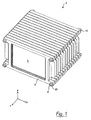
- Fig. 1 is a perspective view of an assembled cell block 2 according to an embodiment of the invention.
- plural (here: fourteen) galvanic cells 4 hereinafter referred to as "cells" are held by a plurality of (here: fifteen) frames 6.
- Two frames 6 each enclose a cell 4.
- the cell block 2 is an arrangement in the sense of the invention.
- the stack of frame 6 and cells 4 is clamped by several (here: four) tie rods 8 so that the stack forms a stable block.
- the tie rods 8 extend through holes (described later) in the frame 6 and are braced by two nuts 10, which are screwed onto the ends of the tie rods 8.
- the tie rods 8 and the nuts 10 are a tensioning device in the context of the invention.
- the space directions are set so that the x-direction corresponds to the stacking direction of the cell block 2, the y-direction corresponds to the width direction of the cell block 2, and the z-direction corresponds to the height direction of the cell block 2 Cell block 2 corresponds.
- the stacking direction x is also referred to as the axial direction, the y-direction as the lateral direction, and the z-direction as the vertical direction.
- Each direction perpendicular to the axial (x) direction, in particular the y and the z direction is also referred to as a radial direction.
- the xy plane forms a horizontal plane and the xz plane and the yz plane form vertical planes.
- These direction definitions relate solely to the cell block 2 itself, but do not exclude that the arrangement shown according to the invention is used in a different global spatial position.
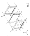
- Fig. 2 is an exploded perspective view of a galvanic cell with two frames of the cell block after Fig. 1 ,
- the cells 4 are lithium-ion cells in the form of so-called flat cells, also called pouch cells or coffeebag cells. These galvanic cells 4 have an active part (main part) 12, which has the shape of a flat cuboid. In the active part 12 takes place an electrochemical reaction for storage and delivery of electrical energy (charging and discharging reaction).
- the inner structure of the active part 12, not shown in detail in the figure, corresponds to a flat, laminated stack of electrochemically active electrode foils of two types (cathode and anode), electrically conductive foils for collecting and supplying or discharging electrical current to and from the electrochemically active regions , and separator foils for separating the electrochemically active regions of the two types from each other.
- At least one kind of the electrochemically active electrode sheets has a lithium compound.
- the cells 4 are thus lithium-ion, lithium-polymer battery cells or similar cells from the family of lithium batteries.
- a separator is formed with a fleece of electrically non-conductive fibers, wherein the fleece is coated on at least one side with an inorganic material.
- the EP 1 017 476 B1 describes such a separator and a method for its production. A separator with the above properties is currently called “ Separion "from Evonik AG, Germany and, available.
- the active part 12 of cell 4 is defined by two in Fig. 2 Unspecified films (32 in Fig. 4 and 5 sandwiched.
- the two films are gas-tight and moisture-tight welded at their free ends and form a so-called sealed seam 14, which surrounds the active part 12 as a circumferential, in the radial direction dissipative, inactive edge zone.
- the active part 12 is also evacuated so that the envelopes fit snugly. The trapped by the envelopes active part 12, without the sealing seam, geometrically forms a main part of the cell 4 according to the invention.
- Two current conductors 16 protrude out of the interior of the cell 4 at the lateral narrow sides of the cell 4 (opposite in the y direction or width direction) through the sealed seam 14 and are accessible there as flat structures.
- the current conductors 16 are connected to the electrochemically active cathode and anode regions in the interior of the active region 12 and thus serve as cathode and anode connections of the cell 4.
- the frame 6 are formed of four circumferential bars 18, 20, 18, 20.
- the vertical bars 18 are distinguished from the horizontal bars 20.
- the horizontal bars 20 continue beyond the boundaries of the vertical beams 18 as tabs 22 in the horizontal direction.
- the tabs 22 may have a different cross-section than the horizontal bars 20. In particular, they may or may not have a different vertical strength than the horizontal beams 20.
- Through each tab 22 extends in the x direction (stacking direction) has a bore 24.
- the holes 24 are used to hold the tie rods 8 (FIG. Fig. 1 ), here only by their axis lines (dash-dotted lines in Fig. 2 ) are indicated. Accordingly, the frame 6 of the cell block 2 are quasi threaded onto the tie rods 8 extending through the bores 24 of the tabs 22.
- the bars 18, 20 form a closed frame, thus rewrite a window 26.
- the beams 18, 20 each have two grooves 28, each of the end faces (ie those sides whose Surface normal along the stacking direction) are introduced here forth so that a circumferential, projecting into the window 26 web 30 stops.
- the area in the radial direction between the grooves 28 and in the axial direction between the webs 30 of two adjacent frame 6 form a free space between frame elements in the context of the invention.
- the current conductors 16 extend between the vertical beams 18 of the adjacent frames 6 and are freely accessible from the sides of the frames, being framed in the vertical direction by the tabs 22 and thus protected from accidental contact.
- the current collector 16 are accessible from the side and can be contacted by suitable connecting elements (not shown); Likewise, the compounds can be solved without complete disassembly of the cell block 2, such as for maintenance or measurement purposes.
- the cells 4 in the cell block 2 (FIG. Fig. 1 ) arranged with alternating polarity. That is, the cells 4 are arranged so that on each side on which the current conductors 16 are exposed, each positive and negative poles (current conductor 16) alternate with each other. Also not shown in detail in the figure are the already mentioned connecting elements which act on the current conductors 16 and connect them in a suitable manner to a battery or a rechargeable battery. Such a battery is an electric energy storage device according to the invention.
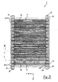
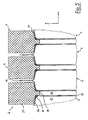
- Fig. 3 is a sectional view of the cell block in Fig. 1 in vertical longitudinal section
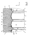
- Fig. 4 is an enlarged view of a detail "IV" in FIG Fig. 3
- the detail "IV" contains the cross-sections of three successive horizontal bars 20 corresponding frame 6 and a part of the adjoining cells 4.
- the section in Fig. 3 and 4 passes through the active part 12 and the sealing seam 14 of the cells 4 and the horizontal bars 20 of the frame 6 Fig. 3 the layer arrangement of the foils within the active part 12 is indicated by parallel lines; in Fig. 4 was waived this presentation.
- the enveloping films 32 are clearly shown.
- Each of the enveloping films 32 is an enveloping film layer in the sense of the invention.
- the narrow sides of the main body of the galvanic cell each have two flanks 34 which extend in cross section in each case from one of the flat sides to a center plane defined between the two flat sides and then pass into the sealed seam 14.
- the grooves 28 and webs 30 follow the outer contour of the active part 12 of the cells 4 (ie their main body) in the region of the narrow sides (flanks 34) and beyond the edge on which the narrow sides pass into the flat side of the cell 4 out ,
- the length (meaning the extent inward) of the webs 30 is limited to the edge region of the flat side of the cell 4. It is preferably no longer than half the thickness, more preferably not more than half the half thickness of the main body of the cell 4.
- flanks 34 and correspondingly also the flutes 28 have a cross-sectional plane x-y, ie to the flat sides of the cells 4, a flank angle ⁇ , which is 90 ° or greater.
- a flank angle ⁇ which is 90 ° or greater.
- a radial and axial centering or guidance between the flanks 34 and the flutes 28 can take place without the edge of the active part 12 abutting the web 30.
- the flank angle ⁇ is not set larger than 120 °, axial portions of guide forces can be limited and the fine adjustment of the distance in the axial direction can be optimized. So overall, a gentle but effective centering can be realized.
- a practicable range for the flank angle ⁇ a range of 92.5 ° to 115 ° has been found, with a range of 95 ° to 110 ° being particularly preferred.
- the sealed seam 14 is free between the horizontal bars 20 at a considerable distance.
- the tension of the tie rods 8 is preferably set so that the grooves 28 exert pressure in the radial direction (transverse to the stacking direction) on the narrow sides (flanks 34) of the main body of the cells 4 (see arrows in FIG Fig. 4 ).
- the cells will be 4 held so reliably in their position, in the radial and axial direction.
- the webs 30 act as an end stop and thus prevent an excessive lateral pressure of the flanks 34.
- the vast majority of the flat sides of the cells 4 is kept free of mechanical stress.
- stop elements can be provided, which ensure that the axial distance between frame 6 does not fall below a predetermined limit.
- Such stop elements may e.g. To be discs that are pushed between the frame 6 respectively via the tie rods 8, or thickening of the frame, in particular in the region of the tabs 22, or the like.
- the clamping forces can be limited to the edges of the cells 4, even if the tie rods 8 are tightened with high torques.
- the grooves 28 and webs 30 follow the outer contour of the active part 12 of the cells 4 in its edge region such that pressure is exerted transversely to the stacking direction on the narrow sides (flanks 34) of the main body of the cells 6, and the seal around freely of clamping forces is.
- the cells 4 are held in the region of the sealed seam 14, in particular where the current conductors 16 pass.
- the thickness (the extent in the stacking direction x) of the horizontal and vertical beams 20, 18 of the frame 6 and the depth of the grooves 28 are adapted to the thickness of the cells 4, the current conductor 16 and the cladding films 32 such that the vertical beams 18 in contact with the enveloping films 32 in the region of the passage of the current collector 16 (see. Fig. 2 ) come before the grooves 28 may come into contact with the edge portions of the active parts 12 of the cells 4 in contact with the flanks 34 or the webs 30.
- the cells 4 are reliably clamped between the frames 6, the seal between the current conductors 16 and the envelopes 32 is free of shear forces.
- Evasive movements of the active parts 12 relative to the frame 6, in particular in the radial direction (directions perpendicular to the stacking direction x), but also in the stacking direction itself, are stopped on the inner contour of the frame 6 (at the groove 28 and the web 30) and so in tight , tolerable limits. Inadmissible mechanical stresses on the enveloping films 32 and the connection points of the current conductors within the cells 4 can therefore also be avoided.
- the frame 6 may be made of a material, such as a plastic, which allows low elastic compressions, and be dimensioned such that the recesses 28 gently abut the flanks 34 of the cells 4 when setting a certain contact pressure of the tie rods 8.
- a material such as a plastic, which allows low elastic compressions, and be dimensioned such that the recesses 28 gently abut the flanks 34 of the cells 4 when setting a certain contact pressure of the tie rods 8.
- Fig. 5 shows in one of the details of Fig. 4 corresponding representation of a modified embodiment of the present invention.
- the structure of the cell block corresponds to that of the embodiment described above except for the deviations discussed below.
- the grooves are replaced by notches 36, which follow the flank angle of the flanks 34, but sharp-edged transition (without noticeable rounding) in a web 38.
- the only difference between the web 38 of this modified embodiment and the web 30 of the previous embodiment is the lack of rounding in the transition to the notch 36.
- an elastomer strip 40 is arranged and shaped - And / or materially attached, which touches the edge between the shoulder 34 and the flat side of the active part 12 of the cell 4.
- a soft support of the active parts 12 of the cells 4 takes place within the frame 6.
- the notch 36 and the web 38 itself touch in this embodiment cell 4 not.
- elastomers in the context of the invention may be any technically meaningful, soft elastic material such as foam, rubber, sponge rubber, or the like or a thin-walled, in cross-section elastically compressible profile, which is for example, without limitation of generality, made of plastic, used.
- the elastomer strip 40 is an elastic element in the sense of the invention.
- Fig. 6 is a perspective, enlarged view of a corner portion of a frame according to the modified embodiment, ie in the transition region between a vertical beam 18 and a horizontal beam 20th
- the elastomeric strip 40 is either glued or directly sprayed on or otherwise secured. It may also be sufficient if the elastomer strip 40 alone holds by its residual stress, since it is held after mounting the cell block 2 positive and non-positive in its position between the cell 4 and the frame 6.
- stop elements can be provided, which ensure that when tightening the tie rods 8 a certain distance between adjacent frame 6 and thus a certain minimum distance between the notches 36 and the edges of the cells 4 is maintained, so that it is ensured only press the elastomer strips 40 with limited force on the flanks.
- This modified embodiment can alternatively be carried out so that the cells 4 are also clamped to the sealing seam 14, preferably in the region of the passage of the current collector 16.
- the elastomer strip 40 would in this case essentially only the task of radial centering and the Damping of axial evasive movements of the main body of the cells 4 meet.
- electric power storage cells of the lithium ion secondary storage (rechargeable battery) type have been described as galvanic cells.
- the term is applicable within the scope of the invention to any type of electric energy storage devices. It can be applied to primary storage (batteries as such) as to secondary storage.
- the nature of the electrochemical reaction for storage and delivery of electrical energy is not limited to lithium-metal oxide reactions, but the individual storage cells may be based on any electrochemical reaction.
- capacitors, supercaps and the like can be arranged in a corresponding manner and
- the number of cells and frames is immaterial to the understanding and scope of the invention. There may be more or fewer than fourteen cells 4 and fifteen frames 6. However, in general, a frame 6 is more present than cells 4, so that each cell 4 is accommodated between every two adjacent frames 6.
- discs or end frame may be provided, on which the nuts 10 rest.
- the sealing seam 14 may be folded in a modification along the upper and lower narrow side and there each form a fold (not shown in detail), which stabilizes the sealing seam at this point and prevents tearing. If the clamping of the cells 4 takes place at the sealing seam 14, the thickness of the fold can be adapted to the thickness of the current conductors 16 including film layers 32, in order to enable a clamping by the vertical and horizontal beams 18, 20 with a uniform beam thickness.
Landscapes
- Chemical & Material Sciences (AREA)
- Chemical Kinetics & Catalysis (AREA)
- Electrochemistry (AREA)
- General Chemical & Material Sciences (AREA)
- Engineering & Computer Science (AREA)
- Manufacturing & Machinery (AREA)
- Life Sciences & Earth Sciences (AREA)
- Sustainable Development (AREA)
- Sustainable Energy (AREA)
- Battery Mounting, Suspending (AREA)
- Connection Of Batteries Or Terminals (AREA)
Applications Claiming Priority (2)
| Application Number | Priority Date | Filing Date | Title |
|---|---|---|---|
| DE102009049043A DE102009049043A1 (de) | 2009-10-12 | 2009-10-12 | Zellblock mit seitlicher Abstützung der Zellen |
| PCT/EP2010/006141 WO2011045000A1 (de) | 2009-10-12 | 2010-10-07 | Zellblock mit seitlicher abstützung der zellen |
Publications (2)
| Publication Number | Publication Date |
|---|---|
| EP2489091A1 EP2489091A1 (de) | 2012-08-22 |
| EP2489091B1 true EP2489091B1 (de) | 2016-01-06 |
Family
ID=43568361
Family Applications (1)
| Application Number | Title | Priority Date | Filing Date |
|---|---|---|---|
| EP10763631.8A Not-in-force EP2489091B1 (de) | 2009-10-12 | 2010-10-07 | Zellblock mit seitlicher abstützung der zellen |
Country Status (8)
| Country | Link |
|---|---|
| US (1) | US20120308864A1 (enExample) |
| EP (1) | EP2489091B1 (enExample) |
| JP (1) | JP2013507744A (enExample) |
| KR (1) | KR20120095900A (enExample) |
| CN (1) | CN102576894A (enExample) |
| BR (1) | BR112012008522A2 (enExample) |
| DE (1) | DE102009049043A1 (enExample) |
| WO (1) | WO2011045000A1 (enExample) |
Families Citing this family (17)
| Publication number | Priority date | Publication date | Assignee | Title |
|---|---|---|---|---|
| DE102010046529A1 (de) * | 2010-09-24 | 2012-03-29 | Volkswagen Ag | Rahmensystem für Batteriezellen sowie Batteriemodul |
| JP2012248416A (ja) * | 2011-05-27 | 2012-12-13 | Sharp Corp | 組電池およびバッテリーシステム |
| DE202011107298U1 (de) * | 2011-10-28 | 2013-01-30 | Li-Tec Battery Gmbh | Zellrahmen einer elektrochemischen Zelle, elektrochemische Zelle mit Zellrahmen und Batterie mit entsprechenden elektrochemischen Zellen |
| JP2013214497A (ja) * | 2012-03-08 | 2013-10-17 | Nissan Motor Co Ltd | 組電池 |
| JP5988669B2 (ja) * | 2012-04-18 | 2016-09-07 | 日立マクセル株式会社 | 電池積層体 |
| JP6160202B2 (ja) * | 2013-04-18 | 2017-07-12 | 日産自動車株式会社 | 電池モジュール |
| AT514491B1 (de) * | 2013-06-20 | 2017-05-15 | Gildemeister Energy Storage Gmbh | Laminierte bipolare Platte |
| DE102013114765A1 (de) | 2013-12-23 | 2015-06-25 | Jungheinrich Aktiengesellschaft | Energiespeicher |
| JP5913445B2 (ja) * | 2014-06-27 | 2016-04-27 | 日本特殊陶業株式会社 | スパークプラグ |
| DE102014013403A1 (de) * | 2014-09-10 | 2016-03-24 | Li-Tec Battery Gmbh | Elektrochemische Energiespeicherzelle mit Rahmeneinrichtung |
| DE102015202894A1 (de) * | 2015-02-18 | 2016-08-18 | Robert Bosch Gmbh | Batteriezelle |
| JP6344293B2 (ja) * | 2015-04-03 | 2018-06-20 | 株式会社デンソー | 電池パック |
| KR102172515B1 (ko) * | 2016-03-16 | 2020-10-30 | 주식회사 엘지화학 | 배터리 모듈 |
| US10381678B2 (en) * | 2016-07-01 | 2019-08-13 | Intel Corporation | Compressed Li-metal battery |
| WO2018234722A1 (en) | 2017-06-19 | 2018-12-27 | Tti (Macao Commercial Offshore) Limited | SURFACE CLEANING APPARATUS |
| FR3071789B1 (fr) * | 2017-10-04 | 2020-07-17 | Valeo Systemes Thermiques | Boitier de support pour batterie |
| KR20200115824A (ko) * | 2019-03-27 | 2020-10-08 | 현대자동차주식회사 | 차량용 배터리 냉각 시스템 |
Family Cites Families (19)
| Publication number | Priority date | Publication date | Assignee | Title |
|---|---|---|---|---|
| US3126302A (en) * | 1964-03-24 | Fuel cell and module | ||
| DE1933305C3 (de) * | 1969-07-01 | 1978-04-06 | Siemens Ag, 1000 Berlin Und 8000 Muenchen | Verfahren zur Herstellung eines Bauteils für Brennstoffelemente |
| JPS60200468A (ja) * | 1984-03-23 | 1985-10-09 | Hitachi Ltd | 燃料電池 |
| DE4309976A1 (de) * | 1993-03-26 | 1994-09-29 | Daimler Benz Ag | Elektrochemische Mehrzellenbatterie |
| PL338474A1 (en) | 1998-06-03 | 2000-11-06 | Creavis Ges F Technologie Und | Hydrophobous permeable compoiste material, method of obtaining same and application thereof |
| US6368740B1 (en) * | 1998-12-29 | 2002-04-09 | Proton Energy Systems, Inc. | Electrochemical cell frame having integral protector portion |
| US20040023090A1 (en) * | 2002-03-30 | 2004-02-05 | Pearson Kenneth E. | Fuel cell system |
| JP3972884B2 (ja) * | 2003-10-10 | 2007-09-05 | 日産自動車株式会社 | 組電池 |
| EP1530247A3 (en) * | 2003-10-10 | 2005-05-18 | Nissan Motor Co., Ltd. | Battery comprising a stack of unit cells and method of making the same |
| JP3897029B2 (ja) * | 2004-03-30 | 2007-03-22 | 日産自動車株式会社 | 組電池用フレームおよび組電池 |
| US9653748B2 (en) * | 2005-04-14 | 2017-05-16 | Enerdel, Inc. | Apparatus and method for securing battery cell packs |
| JP5046505B2 (ja) * | 2005-10-14 | 2012-10-10 | 日本電気株式会社 | 収納ケース、収納部材およびフィルム外装電気デバイス |
| KR100920210B1 (ko) * | 2006-02-09 | 2009-10-05 | 주식회사 엘지화학 | 전지모듈 제조용 프레임 부재 |
| CN101682019B (zh) | 2007-04-24 | 2013-10-23 | 英耐时有限公司 | 具有防错接功能的储能组件 |
| EP2143160A1 (en) | 2007-04-24 | 2010-01-13 | TEMIC Automotive Electric Motors GmbH | Electrochemical cell and energy storage assembly |
| JP2010525552A (ja) | 2007-04-24 | 2010-07-22 | テミツク・オートモテイーベ・エレクトリツク・モータース・ゲゼルシヤフト・ミツト・ベシユレンクテル・ハフツング | 溶接点接続部を持つ電気化学単電池及びエネルギー貯蔵装置 |
| EP2143164A1 (en) | 2007-04-24 | 2010-01-13 | TEMIC Automotive Electric Motors GmbH | Electrochemical cell with a non-graphitizable carbon electrode and energy storage assembly |
| JP2009021067A (ja) * | 2007-07-11 | 2009-01-29 | Fuji Heavy Ind Ltd | 蓄電組立体 |
| US9337456B2 (en) * | 2009-04-20 | 2016-05-10 | Lg Chem, Ltd. | Frame member, frame assembly and battery cell assembly made therefrom and methods of making the same |
-
2009
- 2009-10-12 DE DE102009049043A patent/DE102009049043A1/de not_active Withdrawn
-
2010
- 2010-10-07 EP EP10763631.8A patent/EP2489091B1/de not_active Not-in-force
- 2010-10-07 JP JP2012533513A patent/JP2013507744A/ja active Pending
- 2010-10-07 BR BR112012008522A patent/BR112012008522A2/pt not_active IP Right Cessation
- 2010-10-07 CN CN2010800459188A patent/CN102576894A/zh active Pending
- 2010-10-07 US US13/501,668 patent/US20120308864A1/en not_active Abandoned
- 2010-10-07 KR KR1020127011981A patent/KR20120095900A/ko not_active Withdrawn
- 2010-10-07 WO PCT/EP2010/006141 patent/WO2011045000A1/de not_active Ceased
Also Published As
| Publication number | Publication date |
|---|---|
| EP2489091A1 (de) | 2012-08-22 |
| KR20120095900A (ko) | 2012-08-29 |
| JP2013507744A (ja) | 2013-03-04 |
| US20120308864A1 (en) | 2012-12-06 |
| CN102576894A (zh) | 2012-07-11 |
| DE102009049043A1 (de) | 2011-04-14 |
| BR112012008522A2 (pt) | 2016-04-05 |
| WO2011045000A1 (de) | 2011-04-21 |
Similar Documents
| Publication | Publication Date | Title |
|---|---|---|
| EP2489091B1 (de) | Zellblock mit seitlicher abstützung der zellen | |
| DE69108818T2 (de) | Aufladbare batterie. | |
| EP2517284B1 (de) | Akkumulator mit spannungserzeugenden zellen und dazwischen liegenden ausgleichsplatten | |
| EP2404338B1 (de) | Elektroenergie-speicherzelle und zellblock, elektroenergie-speichervorrichtung und fahrzeug damit | |
| EP2572393B1 (de) | Galvanische zelle | |
| DE102016104036B4 (de) | Batteriepackabstandhalter und Batteriepack | |
| EP2593982B1 (de) | Batteriezellenmodul, batterie und kraftfahrzeug | |
| DE102014216407A1 (de) | Aufnahme für ein Batteriemodul und Batteriemodul aufweisend eine derartige Aufnahme | |
| DE102014221944A1 (de) | Spannvorrichtung zum Verspannen von Speichereinheiten eines elektrischen Energiespeichermoduls und entsprechendes Energiespeichermodul | |
| DE102010013024A1 (de) | Batterie aus einer Vielzahl von Batterieeinzelzellen | |
| DE102010012998A1 (de) | Batterie mit einem Stapel von Batterieeinzelzellen | |
| DE102013016618A1 (de) | Batterieeinzelzelle und Hochvoltbatterie | |
| DE102014106204A1 (de) | Batteriezelle sowie Batterie mit ein oder mehreren Batteriezellen | |
| DE112014004792T5 (de) | Brennstoffzellenstapel mit erhöhter Eigenfreguenz | |
| EP2617085A1 (de) | Elektrochemische energiespeichervorrichtung mit flachzellen und abstandselementen | |
| WO2008098555A1 (de) | Befestigung von energiespeicherzellen in einem gehäuse | |
| DE102013000381A1 (de) | Zellrahmen einer elektrochemischen Zelle, Anordnung von Zellrahmen mit elektrochemischen Zellen und entsprechende Batterie | |
| DE102010013031A1 (de) | Batterie mit einem Zellenstapel von Batterieeinzelzellen | |
| DE102015008275A1 (de) | Zellblock und elektrochemischer Energiespeicher | |
| DE102010014905A1 (de) | Energiespeicherzelleneinheit sowie Energiespeichermodul | |
| AT514595B1 (de) | Zellrahmen für eine Batteriezelle | |
| DE102008043960A1 (de) | Vorrichtung mit mindestens einer Akkumulatorzelle | |
| AT526109B1 (de) | Pouch-Zelle und Batteriepack | |
| DE102021114357A1 (de) | Batteriezellenbaugruppe und Batteriezelle sowie Verfahren zum Herstellen einer Batteriezelle und Verfahren zum Betrieb einer Batteriezelle | |
| AT513835B1 (de) | Wiederaufladbare Batterie |
Legal Events
| Date | Code | Title | Description |
|---|---|---|---|
| PUAI | Public reference made under article 153(3) epc to a published international application that has entered the european phase |
Free format text: ORIGINAL CODE: 0009012 |
|
| 17P | Request for examination filed |
Effective date: 20120502 |
|
| AK | Designated contracting states |
Kind code of ref document: A1 Designated state(s): AL AT BE BG CH CY CZ DE DK EE ES FI FR GB GR HR HU IE IS IT LI LT LU LV MC MK MT NL NO PL PT RO RS SE SI SK SM TR |
|
| DAX | Request for extension of the european patent (deleted) | ||
| RIC1 | Information provided on ipc code assigned before grant |
Ipc: H01M 10/04 20060101ALI20150429BHEP Ipc: H01M 8/24 20060101AFI20150429BHEP Ipc: H01M 8/02 20060101ALI20150429BHEP Ipc: H01M 10/0585 20100101ALI20150429BHEP |
|
| GRAP | Despatch of communication of intention to grant a patent |
Free format text: ORIGINAL CODE: EPIDOSNIGR1 |
|
| INTG | Intention to grant announced |
Effective date: 20150709 |
|
| GRAS | Grant fee paid |
Free format text: ORIGINAL CODE: EPIDOSNIGR3 |
|
| GRAA | (expected) grant |
Free format text: ORIGINAL CODE: 0009210 |
|
| AK | Designated contracting states |
Kind code of ref document: B1 Designated state(s): AL AT BE BG CH CY CZ DE DK EE ES FI FR GB GR HR HU IE IS IT LI LT LU LV MC MK MT NL NO PL PT RO RS SE SI SK SM TR |
|
| REG | Reference to a national code |
Ref country code: GB Ref legal event code: FG4D Free format text: NOT ENGLISH |
|
| REG | Reference to a national code |
Ref country code: CH Ref legal event code: EP |
|
| REG | Reference to a national code |
Ref country code: IE Ref legal event code: FG4D Free format text: LANGUAGE OF EP DOCUMENT: GERMAN |
|
| REG | Reference to a national code |
Ref country code: AT Ref legal event code: REF Ref document number: 769554 Country of ref document: AT Kind code of ref document: T Effective date: 20160215 |
|
| REG | Reference to a national code |
Ref country code: DE Ref legal event code: R096 Ref document number: 502010010902 Country of ref document: DE |
|
| REG | Reference to a national code |
Ref country code: LT Ref legal event code: MG4D |
|
| REG | Reference to a national code |
Ref country code: NL Ref legal event code: MP Effective date: 20160106 |
|
| PG25 | Lapsed in a contracting state [announced via postgrant information from national office to epo] |
Ref country code: NL Free format text: LAPSE BECAUSE OF FAILURE TO SUBMIT A TRANSLATION OF THE DESCRIPTION OR TO PAY THE FEE WITHIN THE PRESCRIBED TIME-LIMIT Effective date: 20160106 |
|
| PG25 | Lapsed in a contracting state [announced via postgrant information from national office to epo] |
Ref country code: ES Free format text: LAPSE BECAUSE OF FAILURE TO SUBMIT A TRANSLATION OF THE DESCRIPTION OR TO PAY THE FEE WITHIN THE PRESCRIBED TIME-LIMIT Effective date: 20160106 Ref country code: IT Free format text: LAPSE BECAUSE OF FAILURE TO SUBMIT A TRANSLATION OF THE DESCRIPTION OR TO PAY THE FEE WITHIN THE PRESCRIBED TIME-LIMIT Effective date: 20160106 Ref country code: NO Free format text: LAPSE BECAUSE OF FAILURE TO SUBMIT A TRANSLATION OF THE DESCRIPTION OR TO PAY THE FEE WITHIN THE PRESCRIBED TIME-LIMIT Effective date: 20160406 Ref country code: GR Free format text: LAPSE BECAUSE OF FAILURE TO SUBMIT A TRANSLATION OF THE DESCRIPTION OR TO PAY THE FEE WITHIN THE PRESCRIBED TIME-LIMIT Effective date: 20160407 Ref country code: FI Free format text: LAPSE BECAUSE OF FAILURE TO SUBMIT A TRANSLATION OF THE DESCRIPTION OR TO PAY THE FEE WITHIN THE PRESCRIBED TIME-LIMIT Effective date: 20160106 Ref country code: HR Free format text: LAPSE BECAUSE OF FAILURE TO SUBMIT A TRANSLATION OF THE DESCRIPTION OR TO PAY THE FEE WITHIN THE PRESCRIBED TIME-LIMIT Effective date: 20160106 |
|
| PG25 | Lapsed in a contracting state [announced via postgrant information from national office to epo] |
Ref country code: PL Free format text: LAPSE BECAUSE OF FAILURE TO SUBMIT A TRANSLATION OF THE DESCRIPTION OR TO PAY THE FEE WITHIN THE PRESCRIBED TIME-LIMIT Effective date: 20160106 Ref country code: LV Free format text: LAPSE BECAUSE OF FAILURE TO SUBMIT A TRANSLATION OF THE DESCRIPTION OR TO PAY THE FEE WITHIN THE PRESCRIBED TIME-LIMIT Effective date: 20160106 Ref country code: IS Free format text: LAPSE BECAUSE OF FAILURE TO SUBMIT A TRANSLATION OF THE DESCRIPTION OR TO PAY THE FEE WITHIN THE PRESCRIBED TIME-LIMIT Effective date: 20160506 Ref country code: PT Free format text: LAPSE BECAUSE OF FAILURE TO SUBMIT A TRANSLATION OF THE DESCRIPTION OR TO PAY THE FEE WITHIN THE PRESCRIBED TIME-LIMIT Effective date: 20160506 Ref country code: LT Free format text: LAPSE BECAUSE OF FAILURE TO SUBMIT A TRANSLATION OF THE DESCRIPTION OR TO PAY THE FEE WITHIN THE PRESCRIBED TIME-LIMIT Effective date: 20160106 Ref country code: SE Free format text: LAPSE BECAUSE OF FAILURE TO SUBMIT A TRANSLATION OF THE DESCRIPTION OR TO PAY THE FEE WITHIN THE PRESCRIBED TIME-LIMIT Effective date: 20160106 Ref country code: RS Free format text: LAPSE BECAUSE OF FAILURE TO SUBMIT A TRANSLATION OF THE DESCRIPTION OR TO PAY THE FEE WITHIN THE PRESCRIBED TIME-LIMIT Effective date: 20160106 |
|
| REG | Reference to a national code |
Ref country code: DE Ref legal event code: R097 Ref document number: 502010010902 Country of ref document: DE |
|
| PG25 | Lapsed in a contracting state [announced via postgrant information from national office to epo] |
Ref country code: EE Free format text: LAPSE BECAUSE OF FAILURE TO SUBMIT A TRANSLATION OF THE DESCRIPTION OR TO PAY THE FEE WITHIN THE PRESCRIBED TIME-LIMIT Effective date: 20160106 Ref country code: DK Free format text: LAPSE BECAUSE OF FAILURE TO SUBMIT A TRANSLATION OF THE DESCRIPTION OR TO PAY THE FEE WITHIN THE PRESCRIBED TIME-LIMIT Effective date: 20160106 |
|
| PLBE | No opposition filed within time limit |
Free format text: ORIGINAL CODE: 0009261 |
|
| STAA | Information on the status of an ep patent application or granted ep patent |
Free format text: STATUS: NO OPPOSITION FILED WITHIN TIME LIMIT |
|
| PG25 | Lapsed in a contracting state [announced via postgrant information from national office to epo] |
Ref country code: CZ Free format text: LAPSE BECAUSE OF FAILURE TO SUBMIT A TRANSLATION OF THE DESCRIPTION OR TO PAY THE FEE WITHIN THE PRESCRIBED TIME-LIMIT Effective date: 20160106 Ref country code: SK Free format text: LAPSE BECAUSE OF FAILURE TO SUBMIT A TRANSLATION OF THE DESCRIPTION OR TO PAY THE FEE WITHIN THE PRESCRIBED TIME-LIMIT Effective date: 20160106 Ref country code: RO Free format text: LAPSE BECAUSE OF FAILURE TO SUBMIT A TRANSLATION OF THE DESCRIPTION OR TO PAY THE FEE WITHIN THE PRESCRIBED TIME-LIMIT Effective date: 20160106 Ref country code: SM Free format text: LAPSE BECAUSE OF FAILURE TO SUBMIT A TRANSLATION OF THE DESCRIPTION OR TO PAY THE FEE WITHIN THE PRESCRIBED TIME-LIMIT Effective date: 20160106 |
|
| 26N | No opposition filed |
Effective date: 20161007 |
|
| PG25 | Lapsed in a contracting state [announced via postgrant information from national office to epo] |
Ref country code: BG Free format text: LAPSE BECAUSE OF FAILURE TO SUBMIT A TRANSLATION OF THE DESCRIPTION OR TO PAY THE FEE WITHIN THE PRESCRIBED TIME-LIMIT Effective date: 20160406 Ref country code: SI Free format text: LAPSE BECAUSE OF FAILURE TO SUBMIT A TRANSLATION OF THE DESCRIPTION OR TO PAY THE FEE WITHIN THE PRESCRIBED TIME-LIMIT Effective date: 20160106 Ref country code: BE Free format text: LAPSE BECAUSE OF NON-PAYMENT OF DUE FEES Effective date: 20161031 |
|
| REG | Reference to a national code |
Ref country code: DE Ref legal event code: R119 Ref document number: 502010010902 Country of ref document: DE |
|
| REG | Reference to a national code |
Ref country code: CH Ref legal event code: PL |
|
| GBPC | Gb: european patent ceased through non-payment of renewal fee |
Effective date: 20161007 |
|
| REG | Reference to a national code |
Ref country code: IE Ref legal event code: MM4A |
|
| REG | Reference to a national code |
Ref country code: FR Ref legal event code: ST Effective date: 20170630 |
|
| PG25 | Lapsed in a contracting state [announced via postgrant information from national office to epo] |
Ref country code: GB Free format text: LAPSE BECAUSE OF NON-PAYMENT OF DUE FEES Effective date: 20161007 Ref country code: DE Free format text: LAPSE BECAUSE OF NON-PAYMENT OF DUE FEES Effective date: 20170503 Ref country code: LI Free format text: LAPSE BECAUSE OF NON-PAYMENT OF DUE FEES Effective date: 20161031 Ref country code: CH Free format text: LAPSE BECAUSE OF NON-PAYMENT OF DUE FEES Effective date: 20161031 Ref country code: FR Free format text: LAPSE BECAUSE OF NON-PAYMENT OF DUE FEES Effective date: 20161102 |
|
| PG25 | Lapsed in a contracting state [announced via postgrant information from national office to epo] |
Ref country code: LU Free format text: LAPSE BECAUSE OF NON-PAYMENT OF DUE FEES Effective date: 20161007 |
|
| PG25 | Lapsed in a contracting state [announced via postgrant information from national office to epo] |
Ref country code: IE Free format text: LAPSE BECAUSE OF NON-PAYMENT OF DUE FEES Effective date: 20161007 |
|
| REG | Reference to a national code |
Ref country code: BE Ref legal event code: MM Effective date: 20161031 |
|
| REG | Reference to a national code |
Ref country code: AT Ref legal event code: MM01 Ref document number: 769554 Country of ref document: AT Kind code of ref document: T Effective date: 20161007 |
|
| PG25 | Lapsed in a contracting state [announced via postgrant information from national office to epo] |
Ref country code: AT Free format text: LAPSE BECAUSE OF NON-PAYMENT OF DUE FEES Effective date: 20161007 |
|
| PG25 | Lapsed in a contracting state [announced via postgrant information from national office to epo] |
Ref country code: HU Free format text: LAPSE BECAUSE OF FAILURE TO SUBMIT A TRANSLATION OF THE DESCRIPTION OR TO PAY THE FEE WITHIN THE PRESCRIBED TIME-LIMIT; INVALID AB INITIO Effective date: 20101007 Ref country code: CY Free format text: LAPSE BECAUSE OF FAILURE TO SUBMIT A TRANSLATION OF THE DESCRIPTION OR TO PAY THE FEE WITHIN THE PRESCRIBED TIME-LIMIT Effective date: 20160106 |
|
| PG25 | Lapsed in a contracting state [announced via postgrant information from national office to epo] |
Ref country code: MK Free format text: LAPSE BECAUSE OF FAILURE TO SUBMIT A TRANSLATION OF THE DESCRIPTION OR TO PAY THE FEE WITHIN THE PRESCRIBED TIME-LIMIT Effective date: 20160106 Ref country code: TR Free format text: LAPSE BECAUSE OF FAILURE TO SUBMIT A TRANSLATION OF THE DESCRIPTION OR TO PAY THE FEE WITHIN THE PRESCRIBED TIME-LIMIT Effective date: 20160106 Ref country code: MT Free format text: LAPSE BECAUSE OF FAILURE TO SUBMIT A TRANSLATION OF THE DESCRIPTION OR TO PAY THE FEE WITHIN THE PRESCRIBED TIME-LIMIT Effective date: 20160106 Ref country code: MC Free format text: LAPSE BECAUSE OF FAILURE TO SUBMIT A TRANSLATION OF THE DESCRIPTION OR TO PAY THE FEE WITHIN THE PRESCRIBED TIME-LIMIT Effective date: 20160106 |
|
| PG25 | Lapsed in a contracting state [announced via postgrant information from national office to epo] |
Ref country code: AL Free format text: LAPSE BECAUSE OF FAILURE TO SUBMIT A TRANSLATION OF THE DESCRIPTION OR TO PAY THE FEE WITHIN THE PRESCRIBED TIME-LIMIT Effective date: 20160106 |