EP2488397B1 - Kraftfahrzeug mit bremsregelvorrichtung - Google Patents
Kraftfahrzeug mit bremsregelvorrichtung Download PDFInfo
- Publication number
- EP2488397B1 EP2488397B1 EP10785468.9A EP10785468A EP2488397B1 EP 2488397 B1 EP2488397 B1 EP 2488397B1 EP 10785468 A EP10785468 A EP 10785468A EP 2488397 B1 EP2488397 B1 EP 2488397B1
- Authority
- EP
- European Patent Office
- Prior art keywords
- braking
- brake
- piston
- pressure
- duct
- Prior art date
- Legal status (The legal status is an assumption and is not a legal conclusion. Google has not performed a legal analysis and makes no representation as to the accuracy of the status listed.)
- Not-in-force
Links
Images


Classifications
-
- B—PERFORMING OPERATIONS; TRANSPORTING
- B62—LAND VEHICLES FOR TRAVELLING OTHERWISE THAN ON RAILS
- B62L—BRAKES SPECIALLY ADAPTED FOR CYCLES
- B62L3/00—Brake-actuating mechanisms; Arrangements thereof
- B62L3/02—Brake-actuating mechanisms; Arrangements thereof for control by a hand lever
- B62L3/023—Brake-actuating mechanisms; Arrangements thereof for control by a hand lever acting on fluid pressure systems
-
- B—PERFORMING OPERATIONS; TRANSPORTING
- B60—VEHICLES IN GENERAL
- B60L—PROPULSION OF ELECTRICALLY-PROPELLED VEHICLES; SUPPLYING ELECTRIC POWER FOR AUXILIARY EQUIPMENT OF ELECTRICALLY-PROPELLED VEHICLES; ELECTRODYNAMIC BRAKE SYSTEMS FOR VEHICLES IN GENERAL; MAGNETIC SUSPENSION OR LEVITATION FOR VEHICLES; MONITORING OPERATING VARIABLES OF ELECTRICALLY-PROPELLED VEHICLES; ELECTRIC SAFETY DEVICES FOR ELECTRICALLY-PROPELLED VEHICLES
- B60L7/00—Electrodynamic brake systems for vehicles in general
- B60L7/10—Dynamic electric regenerative braking
- B60L7/18—Controlling the braking effect
-
- B—PERFORMING OPERATIONS; TRANSPORTING
- B60—VEHICLES IN GENERAL
- B60L—PROPULSION OF ELECTRICALLY-PROPELLED VEHICLES; SUPPLYING ELECTRIC POWER FOR AUXILIARY EQUIPMENT OF ELECTRICALLY-PROPELLED VEHICLES; ELECTRODYNAMIC BRAKE SYSTEMS FOR VEHICLES IN GENERAL; MAGNETIC SUSPENSION OR LEVITATION FOR VEHICLES; MONITORING OPERATING VARIABLES OF ELECTRICALLY-PROPELLED VEHICLES; ELECTRIC SAFETY DEVICES FOR ELECTRICALLY-PROPELLED VEHICLES
- B60L7/00—Electrodynamic brake systems for vehicles in general
- B60L7/24—Electrodynamic brake systems for vehicles in general with additional mechanical or electromagnetic braking
-
- B—PERFORMING OPERATIONS; TRANSPORTING
- B60—VEHICLES IN GENERAL
- B60T—VEHICLE BRAKE CONTROL SYSTEMS OR PARTS THEREOF; BRAKE CONTROL SYSTEMS OR PARTS THEREOF, IN GENERAL; ARRANGEMENT OF BRAKING ELEMENTS ON VEHICLES IN GENERAL; PORTABLE DEVICES FOR PREVENTING UNWANTED MOVEMENT OF VEHICLES; VEHICLE MODIFICATIONS TO FACILITATE COOLING OF BRAKES
- B60T13/00—Transmitting braking action from initiating means to ultimate brake actuator with power assistance or drive; Brake systems incorporating such transmitting means, e.g. air-pressure brake systems
- B60T13/10—Transmitting braking action from initiating means to ultimate brake actuator with power assistance or drive; Brake systems incorporating such transmitting means, e.g. air-pressure brake systems with fluid assistance, drive, or release
- B60T13/58—Combined or convertible systems
- B60T13/585—Combined or convertible systems comprising friction brakes and retarders
- B60T13/586—Combined or convertible systems comprising friction brakes and retarders the retarders being of the electric type
-
- B—PERFORMING OPERATIONS; TRANSPORTING
- B62—LAND VEHICLES FOR TRAVELLING OTHERWISE THAN ON RAILS
- B62K—CYCLES; CYCLE FRAMES; CYCLE STEERING DEVICES; RIDER-OPERATED TERMINAL CONTROLS SPECIALLY ADAPTED FOR CYCLES; CYCLE AXLE SUSPENSIONS; CYCLE SIDECARS, FORECARS, OR THE LIKE
- B62K2204/00—Adaptations for driving cycles by electric motor
Definitions
- the invention relates to the field of braking control devices for mounting on a hydraulic braking circuit of a motorized vehicle to ride.
- a problem that arises relates to the control of the hydraulic control brake / brakes of the vehicle.
- Another problem relates to the control of the electric motor of the vehicle so that it operates in generator, thereby providing regenerative / dynamic braking.
- Yet another problem relates to the design of a solution easy to mount / operate on such motor vehicles to ride.
- Yet another problem relates to progressive braking.
- Another problem concerns the way to secure the repetitiveness of orders, with a solution easy to implement, reliable and inexpensive.
- the piston is moved by action on it of the brake fluid and against a return means , which triggers the operation of the electric motor generator, via a sensor means.
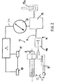
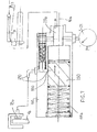
- the motorized riding vehicle 1 is provided with a braking circuit 3.
- It comprises several wheels, preferably two or three, respectively before 4a and rear 4b provided with brakes, respectively 15a, 15b, and a handlebar 5 and an onboard computer 7.
- a braking control device 10 is also embarked at the location of the portion 111 of the duct.
- a brake lever 9 (handle or pedal)
- means 11 for hydraulic pressurization of at least one zone 13 of the circuit and the brakes 15a (front) and 15b (rear ) with hydraulic control.
- the means 11 will be adapted to a hydraulic pressurization. They will include a master cylinder 110 adapted to transmit pressure through a hydraulic fluid.
- the vehicle typically a scooter, also comprises (at least) an electric motor 17 for propulsion adapted to operate as a generator, following a maneuver of said handle or brake pedal 9, and means 19 embedded accumulator of electricity. Electric motor running in motor, they feed it with energy. In generating operation, they are loaded by this engine 17.
- a link 18, for example by chain, allows the motor 17 to transmit the drive energy to the wheel concerned, here 4b.
- Other transmissions are possible: belt, variator, electric motor in the wheel (motor-wheel) ... etc.
- In 200 is schematized the chassis of the vehicle that carries the whole.
- FIG. 2 there is seen a sensor means comprising the pressure sensor 21 adapted to record the pressure in the zone 13 and transmit it to the computer 7 (link 211).
- This zone 13 is provided with valve means 20 arranged in series on the circuit 3.
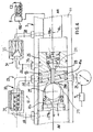
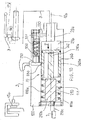
- a "return circuit" 23 of this fluid towards the pressurizing means 110 and mounted locally in parallel with the braking circuit 3 is provided, as shown fig.3 and following.
- valves 27,29 allow fluid communications, respectively at 271 and 291.
- the pressure detected by the transducer / sensor 21 in the zone 13 will depend on the displacement of the piston 25 and the opening and closing conditions of the valves 27, 29 located on either side of it.
- first and second valves 29, 27 they are thus successively arranged on the part of the braking circuit going from the master cylinder 110 to the hydraulically controlled brake, such as 15a, with the output of the first valve and the inlet of the second which are in fluid communication at the location of said zone 13.
- the hydraulic fluid return circuit 23 comprises, as a bypass of the conduit 111, a first section 31 between said zone / pressure chamber 13 and the inlet 29a of the first valve 29, and a second section 33 between the outlet 27b of the second valve 27 and the zone 13.
- first and second circuits 31, 33 are here respectively provided with a reduction of section 35 and a third valve 37.
- the third valve 37 opens, it, at a downstream pressure, at 27b, greater than the pressure in the zone / chamber 13, as shown figure 5 .
- means 39 for selective opening and closing, depending on the pressure transmitted by the hydraulic fluid equip the aforementioned valves. These displacements take place parallel to the axis 10a of the duct 111. Along this axis, the chamber 13 is arranged and the valves 27, 29 and the piston 25 are movable.
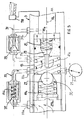
- Figure 3 only all or part of the stroke C1 is depressed.
- the pressure rises at the entrance 29a.
- the piston 25 advances against 41e, but does not close the inlet 31a of the circuit 31.
- the valves 27, 29, 37 are closed.
- the pressure increases in the chamber 13, which is detected by the sensor 21 which translates this into electrical data (or signals) sent into the on-board computer 7.
- the latter engages the regenerative braking, that is to say that the electric motor 17 operates as a generator and charges the accumulator means of electricity, here the battery 19.
- the mechanical braking is not yet activated (delay effect).
- FIG. 5 the driver released the brake handle. Valves 27/25 are closed. The hydraulic fluid returns to the chamber 13 by the bypass 33. The valve 37 is open. The piston 25 starts axially towards the rear (AR), against the return means 41a. At rest, the piston is like figure 3 and the valves 27,29,37 are closed.
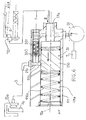
- the valve means 20 comprises a piston 250 sliding in a chamber 111a of the conduit 111, which may be (as in the previous version) an attached section, connected at the input (29a) and at the output (270) to the braking circuit 3, so in series.
- the piston 250 is mounted to act against the return means 410e (here a spring) when it slides forward (AVT), under the effect of the maneuver (crush) of the joystick. brake, in the direction of an opening of the communication 330 (see arrow fig.6 ).
- This communication exists here in the form of an orifice in the side wall of the conduit (chamber 111a).
- This piston is sensitive to the input pressure generated via the stroke of the lever 9 and closes (at least substantially) the communication 330 to the output 270 as the input pressure is below the threshold S2 (see figs.6-7 ). On the other hand, it opens it (by going beyond the orifice) if the input pressure becomes greater than this threshold ( fig.8 ). The means 410e is then compressed to the maximum.
- the joystick 9 is in its second race portion C2.
- the brake concerned (15a here) is tightened.
- the transducer / sensor 21 has further captured the hydraulic pressure P transmitted in the conduit and converted this pressure into electrical data addressed to the computer 7, so that at the threshold S1 the regenerative braking is engaged.
- the race C2 If the race C2 is engaged, it is supposed that there could be cases where the sliding back (arrow fig.6 ) of the piston 250 renders uncertain the return of hydraulic fluid to the inlet 29a through the communication 330 and the entry space 29b of the conduit 111. Also it is advisable to provide, in the body 120 of the conduit, a circuit return 230 between the output 270 and the input 29a, connected bypass means 20/250 valve.
- the circuit 230 comprises a valve 350 opening towards the inlet 29a, against a biasing means 351, when the lever 9 is released, after having been maneuvered beyond the first part (C1) of its braking stroke.
- Figure 10 one finds the version a priori the most accomplished which takes again that of figs.6-9 , except the solid piston 250 which is replaced by the one 260 mounted so as to act physically, during its sliding, on (or interact with) the sensor means 210 which comprises a potentiometer here.
- This sensor mounted with the piston in the chamber 111a of the conduit 111, comprises a rod 210a sliding parallel to the axis 10a of sliding of the piston.
- This piston may be hollow, so as to open and close the lateral orifice 330 as above, via its peripheral side wall 260a.
- the potentiometer 210 here therefore of the linear type, is fixed in the duct and connected to the computer 7. It is therefore thanks to the piston 260 that the hydraulic pressure can be made to act on such a sensor means 210, in order to generate its movement. .
- Other types of potentiometer could be used (rotary ).
- the rod 210a is then moved.
- the importance of the electrical signal sent to the calculator depends on the extent of its displacement.
- the crushing value of the rod 210a corresponding to an electrical value, it is sent to the computer via the link 210c.
- the computer 7 controls the regenerative braking (operation of the electric motor (s), such as 7, as a generator) as a function of the signal it receives, thus the movement undergone by the potentiometer.
- the electric motor 17 will operate as a generator, following the control induced by the data (signals) from the sensor means 210.
- the valve means 260 will close the communication 330 from the input 29b to the output 330 as long as the input pressure P remains below the threshold S2 (S1 ⁇ S2), by opening against this communication if said pressure becomes greater than this threshold.
- the communication 330 will open to trigger the braking of the mechanical brake concerned, such as 15a.
- a clearance j of a few hundredths of a millimeter, typically 2 to 10 / 100mm, between the side wall 260a of the piston and that of the conduit 111, this for a piston diameter of 4 to 10mm, on a length 1 of the order from 5 to 20mm must be suitable for a scooter; see fig.11 where, for the rest, everything is identical to the solution of figs.6-10 . (At least) along the length of the game, the diameter D of the piston is constant.
- the seal 280 will be fixed; it is here carried by the body 120.
- valve 350 open 23.230 bypasses secure the return of hydraulic fluid after the C2 race by avoiding that the brakes concerned remain tight when the brake lever is released.
- Both the pressure sensor 21 and the assembly comprising the potentiometer 210 and the piston 260 define a pressure transducer. Indeed, they provide an electrical signal (typically a voltage signal) from a pressure applied to them. Moreover, the set 210 + 260 can be in one piece. It can therefore be considered that the delay means comprise a pressure transducer.
Landscapes
- Engineering & Computer Science (AREA)
- Mechanical Engineering (AREA)
- Transportation (AREA)
- Power Engineering (AREA)
- Physics & Mathematics (AREA)
- Fluid Mechanics (AREA)
- Electromagnetism (AREA)
- Regulating Braking Force (AREA)
- Valves And Accessory Devices For Braking Systems (AREA)
- Braking Systems And Boosters (AREA)
Claims (8)
- Fahrzeug mit zwei oder drei Rädern und/oder versehen mit einem Richtungslenker (5) und einem Sattel, wobei dieses Fahrzeug Folgendes umfasst:- mindestens einen elektrischen Antriebsmotor (17), der ausgelegt ist, um als Generator zu funktionieren, in Antwort auf eine Bedienung eines beweglichen Bremshebels auf einem ersten Weg, der durch eine Betätigung eines Benutzers bedient werden kann, und verbunden mit mindestens einer Reibungsbremse (15a, 15b) durch einen hydraulischen Bremskreislauf (3),- Mittel (19) zur Speicherung von Elektrizität, die mit dem elektrischen Motor verbunden sind, und- eine Vorrichtung zur Steuerung der Bremsung, umfassend den Bremshebel (9) und Verzögerungsmittel (20, 25, 27, 29, 250, 21, 210, 260), die funktionell mit diesem Hebel, mit der Bremse und mit dem elektrischen Motor verbunden sind, dadurch gekennzeichnet, dass es einen beweglichen Kolben (250, 260) in einer Leitung (111) umfasst, und die Verzögerungsmittel ausgelegt sind, um wenn der Benutzer den Bremshebel bedient, die Anwendung einer Bremsung über die Reibungsbremse(n) auf das Fahrzeug, nach einem ersten Zeitraum des Betriebs des elektrischen Motors als Generator zu verzögern,
ab dem ersten Weg (C1) der Bedienung des Bremshebels der Kolben durch die Einwirkung auf ihn der Bremsflüssigkeit und entgegen einem Rückholmittel (41e) verschoben wird, wodurch der Betrieb des elektrischen Motors (17) als Generator über ein Sensormittel (21, 210) ausgelöst wird. - Verfahren nach Anspruch 1, dadurch gekennzeichnet, dass die Vorrichtung (10) zur Steuerung der Bremsung mit einem hydraulischen Rückleitung (23, 230, 31, 33) ausgestattet ist, die in Umleitung zwischen einem Ausgang (27b, 270) und einem Eingang (29a, 29b) der Leitung (111) montiert ist.
- Vorrichtung zur Steuerung der Bremsung für ein Fahrzeug nach einem der vorhergehenden Ansprüche, und die, montiert auf einem Bremskreislauf (3)und in Verbindung mit einer zweiten Bedienung (C2) des Hebels, die derjenigen gemäß dem ersten Weg (C1) folgt, eine Bremsung über die Reibungsbremse(n) sicherstellt, dadurch gekennzeichnet, dass:- der Kolben, der zu Ventilmitteln (20, 25, 27, 29, 250, 260) gehört, während des ersten Wegs (C1) unter der Einwirkung einer Zirkulierung der hydraulischen Flüssigkeit in diesem Kreislauf verschoben wird,- und das Sensormittel (21, 210), das sie umfasst, ausgelegt ist, um den Druck, der von dieser Flüssigkeit ausgeübt wird, in elektrischen Daten umzuwandeln.
- Vorrichtung nach Anspruch 3, dadurch gekennzeichnet, dass der Kolben:- während des ersten Wegs (C1) solange der hydraulische Druck, der ihn antreibt, unter einer vorbestimmen Schwelle (S2) liegt, eine Verbindung (271, 291, 330) zur Bremse derart schließt, dass keine Bremsung über die Reibungsbremse(n) stattfindet,- während der zweiten Bedienung (C2),und während der hydraulische Druck, der auf ihn ausgeübt wird, größer als die Schwelle (S2) wird, die Verbindung derart öffnet, dass dann eine derartige Bremsung stattfindet.
- Vorrichtung nach Anspruch 3 oder 4, dadurch gekennzeichnet, dass sich in der Leitung (111) und während des/der ersten und zweiten Wegs und Bedienung (C1, C2) des Hebels der Kolben mit Bezug auf eine Öffnung (270, 330) in der seitlichen Wand des Leitung verschiebt, die er öffnet und schließt, je nach seiner Gleitposition.
- Vorrichtung nach einem der Ansprüche 3 bis 5, dadurch gekennzeichnet, dass, sich in der Leitung (111) der Kolben, der eine vollständige Stirnwand (251, 261) aufweist, mit Bezug auf eine Öffnung (270, 330) in der seitlichen Wand des Leitung verschiebt, die er öffnet, indem er gleitet, bis er frontal über sie hinausragt, wobei ein Leckdurchsatz hin zu dieser Öffnung um die periphere seitliche Wand des Kolbens vorhanden ist, auf dem Abschnitt (252, 262), der sich zwischen seiner vorderen Wand und einer Dichtung (280) befindet, wenn sich diese Dichtung jenseits der Öffnung befindet.
- Vorrichtung nach einem der Ansprüche 3 bis 6, dadurch gekennzeichnet, dass das Sensormittel einen Drucksensor (21) umfasst, der in der Leitung (111) angeordnet und ausgelegt ist, um einen Druck, den er dort abgelesen hat, zu übertragen.
- Verfahren zur Durchführung und zur Steuerung der Bremsung auf einem Bremskreislauf (3) eines Fahrzeugs nach Anspruch 1 oder 2, und/oder Vorrichtung (10) zur Steuerung der Bremsung nach einem der Ansprüche 3 bis 7, montiert auf einem derartigen Fahrzeug, das einen Bordcomputer (7) umfasst, einen elektrischen Antriebsmotor (17), der ausgelegt ist, um als Generator zu funktionieren, in Antwort auf eine Bedienung des Bremshebels (9), Bordmittel (19) zur Speicherung von Elektrizität, die ausgelegt sind, um durch den elektrischen Motors (17), der als Generator funktioniert, geladen zu werden, wobei der Eingang der Ventilmittel (20, 25, 27, 29, 250, 260) in fluidischer Verbindung mit den Mitteln (11, 110) zur Unterdrucksetzung verbunden ist, wobei der Ausgang (27b, 270) mit der Bremse (15a, 15b) verbunden ist, und das Sensormittel (21, 210) mit dem Bordcomputer (7) verbunden ist,
wobei in diesem Prozess:- der Eingangsdruck in die elektrischen Daten umgewandelt wird, die an den Computer (7) übertragen werden,- und:- wenn der Druck über einer ersten vorbestimmten Schwelle (S1) liegt, der Kolben durch den Druck der zirkulierenden hydraulischen Flüssigkeit verschoben wird und der elektrische Motor (17) als Generator betrieben wird,- wenn der Druck über einer zweiten vorbestimmten Schwelle (S2) liegt, die selbst höher als die erste Schwelle (S1) ist, durch den Druck der hydraulischen Flüssigkeit weiterhin der Kolben verschoben wird, bis die Verbindung zwischen dem Eingang (29a, 29b) und dem Ausgang (27b, 270) derart geöffnet wird, dass die Betätigung der Bremse (15a, 15b) ausgelöst wird.
Applications Claiming Priority (2)
| Application Number | Priority Date | Filing Date | Title |
|---|---|---|---|
| FR0957212A FR2951131B1 (fr) | 2009-10-14 | 2009-10-14 | Vehicule motorise pourvu d'un dispositif de controle du freinage. |
| PCT/FR2010/052172 WO2011045537A2 (fr) | 2009-10-14 | 2010-10-13 | Vehicule motorise pourvu d'un dispositif de controle du freinage. |
Publications (2)
| Publication Number | Publication Date |
|---|---|
| EP2488397A2 EP2488397A2 (de) | 2012-08-22 |
| EP2488397B1 true EP2488397B1 (de) | 2014-04-23 |
Family
ID=42320752
Family Applications (1)
| Application Number | Title | Priority Date | Filing Date |
|---|---|---|---|
| EP10785468.9A Not-in-force EP2488397B1 (de) | 2009-10-14 | 2010-10-13 | Kraftfahrzeug mit bremsregelvorrichtung |
Country Status (6)
| Country | Link |
|---|---|
| EP (1) | EP2488397B1 (de) |
| CN (1) | CN102648116A (de) |
| BR (1) | BR112012011577A2 (de) |
| FR (1) | FR2951131B1 (de) |
| IN (1) | IN2012DN03046A (de) |
| WO (1) | WO2011045537A2 (de) |
Cited By (1)
| Publication number | Priority date | Publication date | Assignee | Title |
|---|---|---|---|---|
| EP4417502A1 (de) * | 2023-02-20 | 2024-08-21 | HL Mando Corporation | Bremsbetätigungsvorrichtung und fahrrad mit einer bremsbetätigungsvorrichtung |
Family Cites Families (8)
| Publication number | Priority date | Publication date | Assignee | Title |
|---|---|---|---|---|
| SE352574B (de) * | 1968-09-28 | 1973-01-08 | Teves Gmbh Alfred | |
| GB1554161A (en) * | 1976-10-21 | 1979-10-17 | Lucas Industries Ltd | Cycles |
| EP0269547A3 (de) * | 1986-11-05 | 1988-09-07 | Joseph Rogozinski | Bremsanlage |
| CN87205365U (zh) * | 1987-11-21 | 1988-07-20 | 西北建筑工程学院 | 汽车制动能回收装置 |
| JP4662226B2 (ja) * | 2001-09-28 | 2011-03-30 | 本田技研工業株式会社 | 電動補助自転車のインジケータ |
| CN1242891C (zh) * | 2002-11-08 | 2006-02-22 | 刘艳阳 | 汽车制动能和车轮振动能利用装置 |
| FR2874564B1 (fr) * | 2004-08-27 | 2006-12-08 | Peugeot Citroen Automobiles Sa | Dispositif de freinage automobile et vehicule automobile a propulsion electrique equipe d'un tel dispositif de freinage |
| CN101112869B (zh) * | 2007-09-14 | 2010-06-16 | 奇瑞汽车股份有限公司 | 一种汽车能源再生制动系统及其控制方法 |
-
2009
- 2009-10-14 FR FR0957212A patent/FR2951131B1/fr not_active Expired - Fee Related
-
2010
- 2010-10-13 EP EP10785468.9A patent/EP2488397B1/de not_active Not-in-force
- 2010-10-13 BR BR112012011577-4A patent/BR112012011577A2/pt not_active IP Right Cessation
- 2010-10-13 WO PCT/FR2010/052172 patent/WO2011045537A2/fr not_active Ceased
- 2010-10-13 CN CN2010800460382A patent/CN102648116A/zh active Pending
-
2012
- 2012-04-10 IN IN3046DEN2012 patent/IN2012DN03046A/en unknown
Cited By (1)
| Publication number | Priority date | Publication date | Assignee | Title |
|---|---|---|---|---|
| EP4417502A1 (de) * | 2023-02-20 | 2024-08-21 | HL Mando Corporation | Bremsbetätigungsvorrichtung und fahrrad mit einer bremsbetätigungsvorrichtung |
Also Published As
| Publication number | Publication date |
|---|---|
| FR2951131A1 (fr) | 2011-04-15 |
| CN102648116A (zh) | 2012-08-22 |
| WO2011045537A3 (fr) | 2012-03-22 |
| IN2012DN03046A (de) | 2015-07-31 |
| EP2488397A2 (de) | 2012-08-22 |
| FR2951131B1 (fr) | 2012-10-19 |
| BR112012011577A2 (pt) | 2018-06-05 |
| WO2011045537A2 (fr) | 2011-04-21 |
Similar Documents
| Publication | Publication Date | Title |
|---|---|---|
| EP1634787B1 (de) | Kraftfahrzeugbremsvorrichtung | |
| EP0912382B1 (de) | Bremskraftverstärker mit veränderbarer verstärkungsverhaltung | |
| EP2199163B1 (de) | System zur simulierung des bremsgefühls und anwendung eines solchen systems | |
| FR2516037A1 (fr) | Perfectionnements a des systemes de freinage hydraulique antipatinage pour vehicules | |
| FR2505281A1 (fr) | Modulateur de freinage pour systeme de freinage anti-patinant | |
| EP0939713B1 (de) | Hilfskraftbremsvorrichtung mit variablem verstärkerverhältnis und verringerter hysterese | |
| FR2597052A1 (fr) | Systeme hydraulique de freinage equipe d'un dispositif de regulation du glissement de roue | |
| EP2488397B1 (de) | Kraftfahrzeug mit bremsregelvorrichtung | |
| FR2574735A1 (fr) | Amplificateur d'effort de freinage a simulateur de course | |
| EP2098425B1 (de) | Bremssysteme, die die Ausführung eines Stabilitäts- und Bewegungsbahnsteuerverfahrens erlauben | |
| FR2931769A1 (fr) | Systeme de feinage permettant la mise en oeuvre d'un procede de controle de stabilite et de trajectoire dans un vehicule muni d'elements de frein motorises. | |
| FR2576368A1 (fr) | Dispositif d'assistance hydraulique | |
| EP1499815A2 (de) | Scheibenbremse mit mindestens einem neigbaren bremsbelag | |
| EP1538363B1 (de) | Hydraulische Feststellbremse und Verfahren zu deren Verwendung in einer Neigung | |
| EP2102049B1 (de) | Kraftfahrzeugbremsanordnung | |
| FR2931766A1 (fr) | Systeme de freinage avec controle de stabilite et de trajectoire et elements de frein motorises. | |
| FR2931765A1 (fr) | Systeme de freinage avec controle de stabilite et de trajectoire a au moins un element de frein motorise muni d'un systeme de recuperation d'energie mecanique. | |
| EP2253521B1 (de) | Servobremse mit Magnetventil | |
| EP0346171B1 (de) | Hydraulischer Druckerzeuger in Tandembauweise | |
| FR2931764A1 (fr) | Systeme de freinage avec controle de stabilite et de trajectoire a au moins un element de frein motorise muni d'un dispositif de stockage d'energie ainsi qu'une pompe externe. | |
| EP0915790B1 (de) | Hilfskraftunterstütztes bremssystem mit geregelter reaktion | |
| FR2939726A1 (fr) | Vehicule deux ou trois roues et son procede de commande | |
| FR2774642A1 (fr) | Dispositif de limitation de l'effort sur la pedale de freinage d'un vehicule | |
| FR2931767A1 (fr) | Systeme de freinage pour le controle de stabilite et de traj ectoire d'un vehicule automobile et procedes d'utilisation d 'un tel systeme | |
| FR2958900A1 (fr) | Vehicule motorise a controle de freinage |
Legal Events
| Date | Code | Title | Description |
|---|---|---|---|
| PUAI | Public reference made under article 153(3) epc to a published international application that has entered the european phase |
Free format text: ORIGINAL CODE: 0009012 |
|
| 17P | Request for examination filed |
Effective date: 20120326 |
|
| AK | Designated contracting states |
Kind code of ref document: A2 Designated state(s): AL AT BE BG CH CY CZ DE DK EE ES FI FR GB GR HR HU IE IS IT LI LT LU LV MC MK MT NL NO PL PT RO RS SE SI SK SM TR |
|
| DAX | Request for extension of the european patent (deleted) | ||
| GRAP | Despatch of communication of intention to grant a patent |
Free format text: ORIGINAL CODE: EPIDOSNIGR1 |
|
| GRAS | Grant fee paid |
Free format text: ORIGINAL CODE: EPIDOSNIGR3 |
|
| INTG | Intention to grant announced |
Effective date: 20140217 |
|
| GRAA | (expected) grant |
Free format text: ORIGINAL CODE: 0009210 |
|
| AK | Designated contracting states |
Kind code of ref document: B1 Designated state(s): AL AT BE BG CH CY CZ DE DK EE ES FI FR GB GR HR HU IE IS IT LI LT LU LV MC MK MT NL NO PL PT RO RS SE SI SK SM TR |
|
| REG | Reference to a national code |
Ref country code: GB Ref legal event code: FG4D Free format text: NOT ENGLISH |
|
| REG | Reference to a national code |
Ref country code: CH Ref legal event code: EP |
|
| REG | Reference to a national code |
Ref country code: AT Ref legal event code: REF Ref document number: 663640 Country of ref document: AT Kind code of ref document: T Effective date: 20140515 |
|
| REG | Reference to a national code |
Ref country code: IE Ref legal event code: FG4D Free format text: LANGUAGE OF EP DOCUMENT: FRENCH |
|
| REG | Reference to a national code |
Ref country code: DE Ref legal event code: R096 Ref document number: 602010015443 Country of ref document: DE Effective date: 20140605 |
|
| REG | Reference to a national code |
Ref country code: AT Ref legal event code: MK05 Ref document number: 663640 Country of ref document: AT Kind code of ref document: T Effective date: 20140423 |
|
| REG | Reference to a national code |
Ref country code: NL Ref legal event code: VDEP Effective date: 20140423 |
|
| REG | Reference to a national code |
Ref country code: LT Ref legal event code: MG4D |
|
| PG25 | Lapsed in a contracting state [announced via postgrant information from national office to epo] |
Ref country code: NL Free format text: LAPSE BECAUSE OF FAILURE TO SUBMIT A TRANSLATION OF THE DESCRIPTION OR TO PAY THE FEE WITHIN THE PRESCRIBED TIME-LIMIT Effective date: 20140423 Ref country code: LT Free format text: LAPSE BECAUSE OF FAILURE TO SUBMIT A TRANSLATION OF THE DESCRIPTION OR TO PAY THE FEE WITHIN THE PRESCRIBED TIME-LIMIT Effective date: 20140423 Ref country code: NO Free format text: LAPSE BECAUSE OF FAILURE TO SUBMIT A TRANSLATION OF THE DESCRIPTION OR TO PAY THE FEE WITHIN THE PRESCRIBED TIME-LIMIT Effective date: 20140723 Ref country code: BG Free format text: LAPSE BECAUSE OF FAILURE TO SUBMIT A TRANSLATION OF THE DESCRIPTION OR TO PAY THE FEE WITHIN THE PRESCRIBED TIME-LIMIT Effective date: 20140723 Ref country code: CY Free format text: LAPSE BECAUSE OF FAILURE TO SUBMIT A TRANSLATION OF THE DESCRIPTION OR TO PAY THE FEE WITHIN THE PRESCRIBED TIME-LIMIT Effective date: 20140423 Ref country code: GR Free format text: LAPSE BECAUSE OF FAILURE TO SUBMIT A TRANSLATION OF THE DESCRIPTION OR TO PAY THE FEE WITHIN THE PRESCRIBED TIME-LIMIT Effective date: 20140724 Ref country code: IS Free format text: LAPSE BECAUSE OF FAILURE TO SUBMIT A TRANSLATION OF THE DESCRIPTION OR TO PAY THE FEE WITHIN THE PRESCRIBED TIME-LIMIT Effective date: 20140823 Ref country code: FI Free format text: LAPSE BECAUSE OF FAILURE TO SUBMIT A TRANSLATION OF THE DESCRIPTION OR TO PAY THE FEE WITHIN THE PRESCRIBED TIME-LIMIT Effective date: 20140423 |
|
| PG25 | Lapsed in a contracting state [announced via postgrant information from national office to epo] |
Ref country code: AT Free format text: LAPSE BECAUSE OF FAILURE TO SUBMIT A TRANSLATION OF THE DESCRIPTION OR TO PAY THE FEE WITHIN THE PRESCRIBED TIME-LIMIT Effective date: 20140423 Ref country code: SE Free format text: LAPSE BECAUSE OF FAILURE TO SUBMIT A TRANSLATION OF THE DESCRIPTION OR TO PAY THE FEE WITHIN THE PRESCRIBED TIME-LIMIT Effective date: 20140423 Ref country code: PL Free format text: LAPSE BECAUSE OF FAILURE TO SUBMIT A TRANSLATION OF THE DESCRIPTION OR TO PAY THE FEE WITHIN THE PRESCRIBED TIME-LIMIT Effective date: 20140423 Ref country code: LV Free format text: LAPSE BECAUSE OF FAILURE TO SUBMIT A TRANSLATION OF THE DESCRIPTION OR TO PAY THE FEE WITHIN THE PRESCRIBED TIME-LIMIT Effective date: 20140423 Ref country code: RS Free format text: LAPSE BECAUSE OF FAILURE TO SUBMIT A TRANSLATION OF THE DESCRIPTION OR TO PAY THE FEE WITHIN THE PRESCRIBED TIME-LIMIT Effective date: 20140423 Ref country code: ES Free format text: LAPSE BECAUSE OF FAILURE TO SUBMIT A TRANSLATION OF THE DESCRIPTION OR TO PAY THE FEE WITHIN THE PRESCRIBED TIME-LIMIT Effective date: 20140423 Ref country code: HR Free format text: LAPSE BECAUSE OF FAILURE TO SUBMIT A TRANSLATION OF THE DESCRIPTION OR TO PAY THE FEE WITHIN THE PRESCRIBED TIME-LIMIT Effective date: 20140423 |
|
| PG25 | Lapsed in a contracting state [announced via postgrant information from national office to epo] |
Ref country code: PT Free format text: LAPSE BECAUSE OF FAILURE TO SUBMIT A TRANSLATION OF THE DESCRIPTION OR TO PAY THE FEE WITHIN THE PRESCRIBED TIME-LIMIT Effective date: 20140825 |
|
| REG | Reference to a national code |
Ref country code: DE Ref legal event code: R097 Ref document number: 602010015443 Country of ref document: DE |
|
| PG25 | Lapsed in a contracting state [announced via postgrant information from national office to epo] |
Ref country code: SK Free format text: LAPSE BECAUSE OF FAILURE TO SUBMIT A TRANSLATION OF THE DESCRIPTION OR TO PAY THE FEE WITHIN THE PRESCRIBED TIME-LIMIT Effective date: 20140423 Ref country code: DK Free format text: LAPSE BECAUSE OF FAILURE TO SUBMIT A TRANSLATION OF THE DESCRIPTION OR TO PAY THE FEE WITHIN THE PRESCRIBED TIME-LIMIT Effective date: 20140423 Ref country code: RO Free format text: LAPSE BECAUSE OF FAILURE TO SUBMIT A TRANSLATION OF THE DESCRIPTION OR TO PAY THE FEE WITHIN THE PRESCRIBED TIME-LIMIT Effective date: 20140423 Ref country code: CZ Free format text: LAPSE BECAUSE OF FAILURE TO SUBMIT A TRANSLATION OF THE DESCRIPTION OR TO PAY THE FEE WITHIN THE PRESCRIBED TIME-LIMIT Effective date: 20140423 Ref country code: EE Free format text: LAPSE BECAUSE OF FAILURE TO SUBMIT A TRANSLATION OF THE DESCRIPTION OR TO PAY THE FEE WITHIN THE PRESCRIBED TIME-LIMIT Effective date: 20140423 |
|
| PLBE | No opposition filed within time limit |
Free format text: ORIGINAL CODE: 0009261 |
|
| STAA | Information on the status of an ep patent application or granted ep patent |
Free format text: STATUS: NO OPPOSITION FILED WITHIN TIME LIMIT |
|
| PG25 | Lapsed in a contracting state [announced via postgrant information from national office to epo] |
Ref country code: IT Free format text: LAPSE BECAUSE OF FAILURE TO SUBMIT A TRANSLATION OF THE DESCRIPTION OR TO PAY THE FEE WITHIN THE PRESCRIBED TIME-LIMIT Effective date: 20140423 |
|
| 26N | No opposition filed |
Effective date: 20150126 |
|
| REG | Reference to a national code |
Ref country code: DE Ref legal event code: R097 Ref document number: 602010015443 Country of ref document: DE Effective date: 20150126 |
|
| PG25 | Lapsed in a contracting state [announced via postgrant information from national office to epo] |
Ref country code: LU Free format text: LAPSE BECAUSE OF FAILURE TO SUBMIT A TRANSLATION OF THE DESCRIPTION OR TO PAY THE FEE WITHIN THE PRESCRIBED TIME-LIMIT Effective date: 20141013 Ref country code: MC Free format text: LAPSE BECAUSE OF FAILURE TO SUBMIT A TRANSLATION OF THE DESCRIPTION OR TO PAY THE FEE WITHIN THE PRESCRIBED TIME-LIMIT Effective date: 20140423 |
|
| REG | Reference to a national code |
Ref country code: CH Ref legal event code: PL |
|
| GBPC | Gb: european patent ceased through non-payment of renewal fee |
Effective date: 20141013 |
|
| REG | Reference to a national code |
Ref country code: IE Ref legal event code: MM4A |
|
| PG25 | Lapsed in a contracting state [announced via postgrant information from national office to epo] |
Ref country code: CH Free format text: LAPSE BECAUSE OF NON-PAYMENT OF DUE FEES Effective date: 20141031 Ref country code: GB Free format text: LAPSE BECAUSE OF NON-PAYMENT OF DUE FEES Effective date: 20141013 Ref country code: LI Free format text: LAPSE BECAUSE OF NON-PAYMENT OF DUE FEES Effective date: 20141031 Ref country code: SI Free format text: LAPSE BECAUSE OF FAILURE TO SUBMIT A TRANSLATION OF THE DESCRIPTION OR TO PAY THE FEE WITHIN THE PRESCRIBED TIME-LIMIT Effective date: 20140423 |
|
| PG25 | Lapsed in a contracting state [announced via postgrant information from national office to epo] |
Ref country code: IE Free format text: LAPSE BECAUSE OF NON-PAYMENT OF DUE FEES Effective date: 20141013 |
|
| PG25 | Lapsed in a contracting state [announced via postgrant information from national office to epo] |
Ref country code: SM Free format text: LAPSE BECAUSE OF FAILURE TO SUBMIT A TRANSLATION OF THE DESCRIPTION OR TO PAY THE FEE WITHIN THE PRESCRIBED TIME-LIMIT Effective date: 20140423 |
|
| PG25 | Lapsed in a contracting state [announced via postgrant information from national office to epo] |
Ref country code: HU Free format text: LAPSE BECAUSE OF FAILURE TO SUBMIT A TRANSLATION OF THE DESCRIPTION OR TO PAY THE FEE WITHIN THE PRESCRIBED TIME-LIMIT; INVALID AB INITIO Effective date: 20101013 Ref country code: TR Free format text: LAPSE BECAUSE OF FAILURE TO SUBMIT A TRANSLATION OF THE DESCRIPTION OR TO PAY THE FEE WITHIN THE PRESCRIBED TIME-LIMIT Effective date: 20140423 Ref country code: MT Free format text: LAPSE BECAUSE OF FAILURE TO SUBMIT A TRANSLATION OF THE DESCRIPTION OR TO PAY THE FEE WITHIN THE PRESCRIBED TIME-LIMIT Effective date: 20140423 |
|
| REG | Reference to a national code |
Ref country code: FR Ref legal event code: PLFP Year of fee payment: 7 |
|
| PGFP | Annual fee paid to national office [announced via postgrant information from national office to epo] |
Ref country code: FR Payment date: 20160916 Year of fee payment: 7 |
|
| PGFP | Annual fee paid to national office [announced via postgrant information from national office to epo] |
Ref country code: DE Payment date: 20161019 Year of fee payment: 7 |
|
| PGFP | Annual fee paid to national office [announced via postgrant information from national office to epo] |
Ref country code: BE Payment date: 20161020 Year of fee payment: 7 |
|
| REG | Reference to a national code |
Ref country code: DE Ref legal event code: R119 Ref document number: 602010015443 Country of ref document: DE |
|
| PG25 | Lapsed in a contracting state [announced via postgrant information from national office to epo] |
Ref country code: MK Free format text: LAPSE BECAUSE OF FAILURE TO SUBMIT A TRANSLATION OF THE DESCRIPTION OR TO PAY THE FEE WITHIN THE PRESCRIBED TIME-LIMIT Effective date: 20140423 |
|
| REG | Reference to a national code |
Ref country code: FR Ref legal event code: ST Effective date: 20180629 |
|
| PG25 | Lapsed in a contracting state [announced via postgrant information from national office to epo] |
Ref country code: DE Free format text: LAPSE BECAUSE OF NON-PAYMENT OF DUE FEES Effective date: 20180501 |
|
| REG | Reference to a national code |
Ref country code: BE Ref legal event code: MM Effective date: 20171031 |
|
| PG25 | Lapsed in a contracting state [announced via postgrant information from national office to epo] |
Ref country code: FR Free format text: LAPSE BECAUSE OF NON-PAYMENT OF DUE FEES Effective date: 20171031 Ref country code: BE Free format text: LAPSE BECAUSE OF NON-PAYMENT OF DUE FEES Effective date: 20171031 |
|
| PG25 | Lapsed in a contracting state [announced via postgrant information from national office to epo] |
Ref country code: AL Free format text: LAPSE BECAUSE OF FAILURE TO SUBMIT A TRANSLATION OF THE DESCRIPTION OR TO PAY THE FEE WITHIN THE PRESCRIBED TIME-LIMIT Effective date: 20140423 |