EP2488006A2 - Temperaturausgleichsvorrichtung zum Sprühen von Flüssigkeit für die thermische Leitung unter Verwendung in elektrischen Geräten - Google Patents
Temperaturausgleichsvorrichtung zum Sprühen von Flüssigkeit für die thermische Leitung unter Verwendung in elektrischen Geräten Download PDFInfo
- Publication number
- EP2488006A2 EP2488006A2 EP12155190A EP12155190A EP2488006A2 EP 2488006 A2 EP2488006 A2 EP 2488006A2 EP 12155190 A EP12155190 A EP 12155190A EP 12155190 A EP12155190 A EP 12155190A EP 2488006 A2 EP2488006 A2 EP 2488006A2
- Authority
- EP
- European Patent Office
- Prior art keywords
- fluid
- thermal conductive
- electric
- thermal
- conductive fluid
- Prior art date
- Legal status (The legal status is an assumption and is not a legal conclusion. Google has not performed a legal analysis and makes no representation as to the accuracy of the status listed.)
- Granted
Links
Images




Classifications
-
- H—ELECTRICITY
- H05—ELECTRIC TECHNIQUES NOT OTHERWISE PROVIDED FOR
- H05K—PRINTED CIRCUITS; CASINGS OR CONSTRUCTIONAL DETAILS OF ELECTRIC APPARATUS; MANUFACTURE OF ASSEMBLAGES OF ELECTRICAL COMPONENTS
- H05K7/00—Constructional details common to different types of electric apparatus
- H05K7/20—Modifications to facilitate cooling, ventilating, or heating
- H05K7/20218—Modifications to facilitate cooling, ventilating, or heating using a liquid coolant without phase change in electronic enclosures
- H05K7/20254—Cold plates transferring heat from heat source to coolant
-
- F—MECHANICAL ENGINEERING; LIGHTING; HEATING; WEAPONS; BLASTING
- F28—HEAT EXCHANGE IN GENERAL
- F28D—HEAT-EXCHANGE APPARATUS, NOT PROVIDED FOR IN ANOTHER SUBCLASS, IN WHICH THE HEAT-EXCHANGE MEDIA DO NOT COME INTO DIRECT CONTACT
- F28D15/00—Heat-exchange apparatus with the intermediate heat-transfer medium in closed tubes passing into or through the conduit walls ; Heat-exchange apparatus employing intermediate heat-transfer medium or bodies
-
- F—MECHANICAL ENGINEERING; LIGHTING; HEATING; WEAPONS; BLASTING
- F28—HEAT EXCHANGE IN GENERAL
- F28D—HEAT-EXCHANGE APPARATUS, NOT PROVIDED FOR IN ANOTHER SUBCLASS, IN WHICH THE HEAT-EXCHANGE MEDIA DO NOT COME INTO DIRECT CONTACT
- F28D15/00—Heat-exchange apparatus with the intermediate heat-transfer medium in closed tubes passing into or through the conduit walls ; Heat-exchange apparatus employing intermediate heat-transfer medium or bodies
- F28D15/02—Heat-exchange apparatus with the intermediate heat-transfer medium in closed tubes passing into or through the conduit walls ; Heat-exchange apparatus employing intermediate heat-transfer medium or bodies in which the medium condenses and evaporates, e.g. heat pipes
-
- F—MECHANICAL ENGINEERING; LIGHTING; HEATING; WEAPONS; BLASTING
- F28—HEAT EXCHANGE IN GENERAL
- F28D—HEAT-EXCHANGE APPARATUS, NOT PROVIDED FOR IN ANOTHER SUBCLASS, IN WHICH THE HEAT-EXCHANGE MEDIA DO NOT COME INTO DIRECT CONTACT
- F28D15/00—Heat-exchange apparatus with the intermediate heat-transfer medium in closed tubes passing into or through the conduit walls ; Heat-exchange apparatus employing intermediate heat-transfer medium or bodies
- F28D15/02—Heat-exchange apparatus with the intermediate heat-transfer medium in closed tubes passing into or through the conduit walls ; Heat-exchange apparatus employing intermediate heat-transfer medium or bodies in which the medium condenses and evaporates, e.g. heat pipes
- F28D15/0233—Heat-exchange apparatus with the intermediate heat-transfer medium in closed tubes passing into or through the conduit walls ; Heat-exchange apparatus employing intermediate heat-transfer medium or bodies in which the medium condenses and evaporates, e.g. heat pipes the conduits having a particular shape, e.g. non-circular cross-section, annular
-
- F—MECHANICAL ENGINEERING; LIGHTING; HEATING; WEAPONS; BLASTING
- F28—HEAT EXCHANGE IN GENERAL
- F28D—HEAT-EXCHANGE APPARATUS, NOT PROVIDED FOR IN ANOTHER SUBCLASS, IN WHICH THE HEAT-EXCHANGE MEDIA DO NOT COME INTO DIRECT CONTACT
- F28D20/00—Heat storage plants or apparatus in general; Regenerative heat-exchange apparatus not covered by groups F28D17/00 or F28D19/00
-
- F—MECHANICAL ENGINEERING; LIGHTING; HEATING; WEAPONS; BLASTING
- F28—HEAT EXCHANGE IN GENERAL
- F28D—HEAT-EXCHANGE APPARATUS, NOT PROVIDED FOR IN ANOTHER SUBCLASS, IN WHICH THE HEAT-EXCHANGE MEDIA DO NOT COME INTO DIRECT CONTACT
- F28D20/00—Heat storage plants or apparatus in general; Regenerative heat-exchange apparatus not covered by groups F28D17/00 or F28D19/00
- F28D20/0034—Heat storage plants or apparatus in general; Regenerative heat-exchange apparatus not covered by groups F28D17/00 or F28D19/00 using liquid heat storage material
-
- H—ELECTRICITY
- H05—ELECTRIC TECHNIQUES NOT OTHERWISE PROVIDED FOR
- H05K—PRINTED CIRCUITS; CASINGS OR CONSTRUCTIONAL DETAILS OF ELECTRIC APPARATUS; MANUFACTURE OF ASSEMBLAGES OF ELECTRICAL COMPONENTS
- H05K7/00—Constructional details common to different types of electric apparatus
- H05K7/20—Modifications to facilitate cooling, ventilating, or heating
- H05K7/20218—Modifications to facilitate cooling, ventilating, or heating using a liquid coolant without phase change in electronic enclosures
- H05K7/20272—Accessories for moving fluid, for expanding fluid, for connecting fluid conduits, for distributing fluid, for removing gas or for preventing leakage, e.g. pumps, tanks or manifolds
-
- H—ELECTRICITY
- H05—ELECTRIC TECHNIQUES NOT OTHERWISE PROVIDED FOR
- H05K—PRINTED CIRCUITS; CASINGS OR CONSTRUCTIONAL DETAILS OF ELECTRIC APPARATUS; MANUFACTURE OF ASSEMBLAGES OF ELECTRICAL COMPONENTS
- H05K7/00—Constructional details common to different types of electric apparatus
- H05K7/20—Modifications to facilitate cooling, ventilating, or heating
- H05K7/2029—Modifications to facilitate cooling, ventilating, or heating using a liquid coolant with phase change in electronic enclosures
- H05K7/20345—Sprayers; Atomizers
-
- H—ELECTRICITY
- H05—ELECTRIC TECHNIQUES NOT OTHERWISE PROVIDED FOR
- H05K—PRINTED CIRCUITS; CASINGS OR CONSTRUCTIONAL DETAILS OF ELECTRIC APPARATUS; MANUFACTURE OF ASSEMBLAGES OF ELECTRICAL COMPONENTS
- H05K7/00—Constructional details common to different types of electric apparatus
- H05K7/20—Modifications to facilitate cooling, ventilating, or heating
- H05K7/2029—Modifications to facilitate cooling, ventilating, or heating using a liquid coolant with phase change in electronic enclosures
- H05K7/20381—Thermal management, e.g. evaporation control
-
- H—ELECTRICITY
- H10—SEMICONDUCTOR DEVICES; ELECTRIC SOLID-STATE DEVICES NOT OTHERWISE PROVIDED FOR
- H10W—GENERIC PACKAGES, INTERCONNECTIONS, CONNECTORS OR OTHER CONSTRUCTIONAL DETAILS OF DEVICES COVERED BY CLASS H10
- H10W40/00—Arrangements for thermal protection or thermal control
- H10W40/40—Arrangements for thermal protection or thermal control involving heat exchange by flowing fluids
- H10W40/47—Arrangements for thermal protection or thermal control involving heat exchange by flowing fluids by flowing liquids, e.g. forced water cooling
- H10W40/475—Arrangements for thermal protection or thermal control involving heat exchange by flowing fluids by flowing liquids, e.g. forced water cooling using jet impingement
-
- F—MECHANICAL ENGINEERING; LIGHTING; HEATING; WEAPONS; BLASTING
- F17—STORING OR DISTRIBUTING GASES OR LIQUIDS
- F17C—VESSELS FOR CONTAINING OR STORING COMPRESSED, LIQUEFIED OR SOLIDIFIED GASES; FIXED-CAPACITY GAS-HOLDERS; FILLING VESSELS WITH, OR DISCHARGING FROM VESSELS, COMPRESSED, LIQUEFIED, OR SOLIDIFIED GASES
- F17C2227/00—Transfer of fluids, i.e. method or means for transferring the fluid; Heat exchange with the fluid
- F17C2227/03—Heat exchange with the fluid
- F17C2227/0367—Localisation of heat exchange
- F17C2227/0388—Localisation of heat exchange separate
- F17C2227/0395—Localisation of heat exchange separate using a submerged heat exchanger
-
- Y—GENERAL TAGGING OF NEW TECHNOLOGICAL DEVELOPMENTS; GENERAL TAGGING OF CROSS-SECTIONAL TECHNOLOGIES SPANNING OVER SEVERAL SECTIONS OF THE IPC; TECHNICAL SUBJECTS COVERED BY FORMER USPC CROSS-REFERENCE ART COLLECTIONS [XRACs] AND DIGESTS
- Y02—TECHNOLOGIES OR APPLICATIONS FOR MITIGATION OR ADAPTATION AGAINST CLIMATE CHANGE
- Y02E—REDUCTION OF GREENHOUSE GAS [GHG] EMISSIONS, RELATED TO ENERGY GENERATION, TRANSMISSION OR DISTRIBUTION
- Y02E60/00—Enabling technologies; Technologies with a potential or indirect contribution to GHG emissions mitigation
- Y02E60/14—Thermal energy storage
Definitions
- the present invention discloses an external thermal conduction interface structure of electrical equipment (101) wherein a fluid jetting device (103) is utilized to jet a thermal conductive fluid (104) for exchanging heat with the external thermal conduction interface structure of electrical equipment (101) via the thermal energy of the jetted thermal conductive fluid (104), the heat exchange means includes the external thermal conduction interface structure of electrical equipment (101) having relative high temperature being cooled by a fluid having relative lower temperature, and the external thermal conduction interface structure of electrical equipment (101) having relative lower temperature being heated by a fluid having relative higher temperature;
- the fluid jetted by the fluid jetting device (103) includes the thermal conductive fluid (104) in a liquid state or in a particle liquid or mist or gaseous state, or the thermal conductive fluid (104) capable of converting into a gaseous state from a liquid state or converting into a liquid state from a gaseous state, and a fluid collecting basin (105) is installed for collecting the returned fluid which is jetted to the external thermal conduction interface structure of electrical equipment (101), so as to form a circulative operation of the thermal conductive fluid (104), and the thermal conductive fluid (104) and the fluid collecting basin (105) can be served as interfaces for performing temperature equalizing and regulating to the exterior;
- the fluid jetting device (103) of the present invention injects the fluid through the fluid jetting device (103) in a small particle or fine mist state to the external thermal conduction interface structure of electrical equipment (101), such that the fluid in the small particle or fine mist state is enabled to be accelerated for being injected to the surface of the external thermal conduction interface structure of electrical equipment (101) thereby being diffused to films and evaporated, and forcing the gaseous fluid, which has already been evaporated, to be away from the surface of the external thermal conduction interface structure of electrical equipment (101); or a dry-expansion type evaporator, or a flooded type evaporator, or a spray type evaporator, or a falling type evaporator is installed to the external thermal conduction interface structure of electrical equipment (101), so as to constitute temperature equalization operating function of the external thermal conduction interface structure of electrical equipment (101).
- the temperature maintaining, cooling or heating for conventional electrical equipment often needs active temperature regulating devices for temperature maintaining, cooling or heating, the disadvantages thereof are higher installation cost and consuming greater energy in operation.
- the present invention provides a temperature equalization apparatus jetting fluid for thermal conduction used in an electrical equipment, wherein a thermal conductive fluid (104) is jetted to an external thermal conduction interface structure of electrical equipment (101) through a fluid jetting device (103) then returned to a fluid collecting basin (105) for forming a circulation, and the thermal conductive fluid (104) and the fluid collecting basin (105) can be served as interfaces for performing temperature equalizing and regulating to the exterior, and
- the mentioned natural thermal energy body (200) can be a thermal storage member such as an earth surface, stratum, river, lake, artificial water channel or pipeline or pond.
- a heat exchange apparatus comprises:
- the present invention discloses an external thermal conduction interface structure of electrical equipment (101) wherein a fluid jetting device (103) is utilized to jet a thermal conductive fluid (104) for exchanging heat with the external thermal conduction interface structure of electrical equipment (101) via the thermal energy of the jetted thermal conductive fluid (104), the heat exchange means includes the external thermal conduction interface structure of electrical equipment (101) having relative high temperature being cooled by a fluid having relative lower temperature, and the external thermal conduction interface structure of electrical equipment (101) having relative lower temperature being heated by a fluid having relative higher temperature;
- the fluid jetted by the fluid jetting device (103) includes the thermal conductive fluid (104) in a liquid state or in a particle liquid or mist or gaseous state, or the thermal conductive fluid (104) capable of converting into a gaseous state from a liquid state or converting into a liquid state from a gaseous state, and a fluid collecting basin (105) is installed for collecting the returned fluid which is jetted to the external thermal conduction interface structure of electrical equipment (101), so as to form a circulative operation of the thermal conductive fluid (104), and the thermal conductive fluid (104) and the fluid collecting basin (105) can be served as interfaces for performing temperature equalizing and regulating to the exterior;
- the fluid jetting device (103) of the present invention injects the fluid through the fluid jetting device (103) in a small particle or fine mist state to the external thermal conduction interface structure of electrical equipment (101), such that the fluid in the small particle or fine mist state is enabled to be accelerated for being injected to the surface of the external thermal conduction interface structure of electrical equipment (101) thereby being diffused to films and evaporated, and forcing the gaseous fluid, which has already been evaporated, to be away from the surface of the external thermal conduction interface structure of electrical equipment (101); or a dry-expansion type evaporator, or a flooded type evaporator, or a spray type evaporator, or a falling type evaporator is installed to the external thermal conduction interface structure of electrical equipment (101), so as to constitute temperature equalization operating function of the external thermal conduction interface structure of electrical equipment (101).
- the present invention provides a temperature equalization apparatus jetting fluid for thermal conduction used in an electrical equipment, wherein a thermal conductive fluid (104) is jetted to an external thermal conduction interface structure of electrical equipment (101) through a fluid jetting device (103) then returned to a fluid collecting basin (105) for forming a circulation, and the thermal conductive fluid (104) and the fluid collecting basin (105) can be served as interfaces for performing temperature equalizing and regulating to the exterior, and the conduction structure of the thermal conductive fluid (104) performing temperature equalizing and regulating to the exterior includes one or more than one of the following means:
- the mentioned natural thermal energy body (200) can be a thermal storage member such as an earth surface, stratum, river, lake, artificial water channel or pipeline or pond.
- a thermal conductive fluid (104) is jetted to an external thermal conduction interface structure of electrical equipment (101) through a fluid jetting device (103) then returned to a fluid collecting basin (105) for forming a circulation, and the thermal conductive fluid (104) and the fluid collecting basin (105) are served as interfaces for performing temperature equalizing and regulating to the exterior, and the conduction structure of the thermal conductive fluid (104) performing temperature equalizing and regulating to the exterior is as following:
- the thermal conductive fluid (104) in the fluid collecting basin (105) is introduced through a fluid inlet of the fluid jetting device (103) so as to be jetted to the external thermal conduction interface structure of electrical equipment (101), then the thermal conductive fluid (104) is returned to the fluid collecting basin (105) thereby forming the circulation of the thermal conductive fluid (104), and a housing of the fluid collecting basin (105) is served to perform temperature equalizing and regulating to the exterior;
- FIG 1 is a schematic structural view showing the operation of the fluid collecting basin (105) dissipating heat to the exterior, according to the present invention
- FIG 1 it mainly consists of:
- the electric equipment composed of electric machineries or electric controls includes a power supply, an adapter, an electric resistor, a static electric machinery, a motor, a power generator, a turbine transmission device, a revolving electric machinery, an electric machinery driven control device, a converter, an inverter, an electric charging device, a power control device or an electromagnetic control device;
- External thermal conduction interface structure of electrical equipment (101) constituted by an external thermal conduction structure of the electric equipment (100), the surface thereof is provided with a property of being compatible with the thermal conductive fluid (104) and corrosion proof, and provided with an anti-moist structure or an anti-moist layer;
- the mentioned external thermal conduction interface structure of electrical equipment (101) can be horizontally, vertically or obliquely installed for allowing the thermal conductive fluid (104) jetted from the fluid jetting device (103) to return to the fluid collecting basin (105);
- the conduction structure of the thermal conductive fluid (104) performing thermal conduction to the exterior can be further constructed by that the thermal conductive fluid (104) in the outlet of a pipeline (108) of a temperature equalizing device (102) installed in a natural thermal energy body (200) is directly introduced through the fluid introducing pipe (1031) of the fluid jetting device (103) so as to be jetted to the external thermal conduction interface structure of electrical equipment (101), then the thermal conductive fluid (104) is returned to the fluid collecting basin (105), as well as passed through the temperature equalizing device (102) installed in the natural thermal energy body (200), so as to enable the thermal conductive fluid (104) to perform temperature equalizing and regulating with the natural thermal energy body (200) through the temperature equalizing device (102), then returned to the fluid inlet of the fluid jetting device thereby forming the circulation of the thermal conductive fluid (104);
- the mentioned natural thermal energy body (200) can be a thermal storage member such as an earth surface, stratum, river, lake, artificial water channel or pipeline or pond.
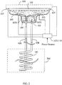
- FIG 2 is a schematic view showing the thermal conductive fluid (104) in the pipeline (108) of the temperature equalizing device (102) being directly introduced through the fluid introducing pipe (1031) of the fluid jetting device (103) and being jetted to the external thermal conduction interface structure of electrical equipment (101), then the thermal conductive fluid (104) being returned to the fluid collecting basin (105), as well as passed through the temperature equalizing device (102) installed in the natural thermal energy body (200), so as to enable the thermal conductive fluid (104) to perform temperature equalizing and regulating with the natural thermal energy body (200) through the temperature equalizing device (102), then returned to the fluid collecting basin (105), according to one embodiment of the present invention;
- FIG 2 it mainly consists of:
- the electric equipment composed of electric machineries or electric controls includes a power supply, an adapter, an electric resistor, a static electric machinery, a motor, a power generator, a turbine transmission device, a revolving electric machinery, an electric machinery driven control device, a converter, an inverter, an electric charging device, a power control device or an electromagnetic control device;
- the mentioned external thermal conduction interface structure of electrical equipment (101) can be horizontally, vertically or obliquely installed for allowing the thermal conductive fluid (104) jetted from the fluid jetting device (103) to return to the fluid collecting basin (105);
- the conduction structure of the thermal conductive fluid (104) performing thermal conduction to the exterior can be further constructed by that the thermal conductive fluid (104) in the fluid collecting basin (105) is introduced through the fluid inlet of the fluid jetting device (103) so as to be jetted to the external thermal conduction interface structure of electrical equipment (101), then the thermal conductive fluid (104) is returned to the fluid collecting basin (105); a fluid pump (106) and a pipeline (108) are installed between the fluid collecting basin (105) and the temperature equalizing device (102) installed in the natural thermal energy body (200); and the thermal conductive fluid (104) in the fluid collecting basin (105) is pumped by the fluid pump (106) to pass through the temperature equalizing device (102) installed in the natural thermal energy body (200) via the pipeline (108), thereby to enable the thermal conductive fluid (104) to perform temperature equalizing and regulating with the natural thermal energy body (200) through the temperature equalizing device (102), then returned to the fluid collecting basin (105) thereby forming
- the mentioned natural thermal energy body (200) can be a thermal storage member such as an earth surface, stratum, river, lake, artificial water channel or pipeline or pond.
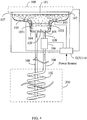
- FIG 3 is a schematic view showing the thermal conductive fluid (104) being pumped through the fluid pump (106) and the pipeline (108) to pass through the temperature equalizing device (102) installed in the natural thermal energy body (200) so as to perform temperature equalizing and regulating with the natural thermal energy body (200), according to one embodiment of the present invention;
- FIG 3 it mainly consists of:
- the electric equipment composed of electric machineries or electric controls includes a power supply, an adapter, an electric resistor, a static electric machinery, a motor, a power generator, a turbine transmission device, a revolving electric machinery, an electric machinery driven control device, a converter, an inverter, an electric charging device, a power control device or an electromagnetic control device;
- the mentioned external thermal conduction interface structure of electrical equipment (101) can be horizontally, vertically or obliquely installed for allowing the thermal conductive fluid (104) jetted from the fluid jetting device (103) to return to the fluid collecting basin (105);
- the conduction structure of the thermal conductive fluid (104) performing thermal conduction to the exterior can further be constructed by that the thermal conductive fluid (104) in the fluid collecting basin (105) is introduced through the fluid inlet of the fluid jetting device (103) so as to be jetted to the external thermal conduction interface structure of electrical equipment (101), then the thermal conductive fluid (104) is returned to the fluid collecting basin (105) thereby forming the circulation of the thermal conductive fluid (104); and a heat exchanging device (120) immersed in the thermal conductive fluid (104) of the fluid collecting basin (105) is installed, the thermal conductive fluid (104) in the heat exchanging device (120) is pumped by a fluid pump (106) installed at the fluid outlet of the heat exchanging device (120) and passed through the temperature equalizing device (102) installed in the natural thermal energy body (200) via the pipeline (108), then returned to the heat exchanging device (120) through the fluid inlet of the heat exchanging device (120), so as to form
- the mentioned natural thermal energy body (200) can be a thermal storage member such as an earth surface, stratum, river, lake, artificial water channel or pipeline or pond.
- FIG 4 is a schematic view showing the thermal conductive fluid (104) in the heat exchanging device (120) immersed in the thermal conductive fluid (104) of the fluid collecting basin (105), through installing the heat exchanging device (120) immersed in the thermal conductive fluid (104) of the fluid collecting basin (105), the fluid pump (106), the pipeline (108) and the temperature equalizing device (102), being pumped by the fluid pump (106) to pass through the temperature equalizing device (102) of the natural thermal energy body (200) via the pipeline (108) for performing temperature equalizing and regulating to the natural thermal energy body (200), according to one embodiment of the present invention;
- FIG 4 it mainly consists of:
- the electric equipment composed of electric machineries or electric controls includes a power supply, an adapter, an electric resistor, a static electric machinery, a motor, a power generator, a turbine transmission device, a revolving electric machinery, an electric machinery driven control device, a converter, an inverter, an electric charging device, a power control device or an electromagnetic control device;
- External thermal conduction interface structure of electrical equipment (101) constituted by an external thermal conduction structure of the electric equipment (100), the surface thereof is provided with a property of being compatible with the thermal conductive fluid (104) and corrosion proof, and provided with an anti-moist structure or an anti-moist layer;
- the mentioned external thermal conduction interface structure of electrical equipment (101) can be horizontally, vertically or obliquely installed for allowing the thermal conductive fluid (104) jetted from the fluid jetting device (103) to return to the fluid collecting basin (105);
- the conduction structure of the thermal conductive fluid (104) conducting thermal energy to the exterior can further be constructed by that a relay heat exchanging device (121) is installed between the fluid collecting basin (105) and the temperature equalizing device (102), the fluid inlet at the primary side of the relay heat exchanging device (121) is communicated to the fluid collecting basin (105), the system operation is that the thermal conductive fluid (104) at the fluid outlet at the primary side of the relay heat exchanging device (121) is directly introduced through the fluid introducing pipe (1031) of the fluid jetting device (103) so as to be jetted to the external thermal conduction interface structure of electrical equipment (101), then the thermal conductive fluid (104) is returned to the fluid collecting basin (105) and further flowed to the fluid inlet at the primary side of the relay heat exchanging device (121), thereby forming the circulation of the thermal conductive fluid (104) at the primary side of the relay heat exchanging device (121); and a fluid pump (106) is installed between the fluid inlet
- the mentioned natural thermal energy body (200) can be a thermal storage member such as an earth surface, stratum, river, lake, artificial water channel or pipeline or pond;
- FIG 5 is a schematic view showing the present invention being installed with the relay heat exchanging device (121), wherein the primary side thereof being communicated to the fluid collecting basin (105), the fluid pump (106) and the pipeline (108) being installed between the secondary side thereof and the temperature equalizing device (102) installed in the natural thermal energy body (200) for pumping the thermal conductive fluid (104) to pass through the temperature equalizing device (102) for performing temperature equalizing and regulating to the natural thermal energy body (200);
- FIG 5 it mainly consists of:
- the electric equipment composed of electric machineries or electric controls includes a power supply, an adapter, an electric resistor, a static electric machinery, a motor, a power generator, a turbine transmission device, a revolving electric machinery, an electric machinery driven control device, a converter, an inverter, an electric charging device, a power control device or an electromagnetic control device;
- the mentioned external thermal conduction interface structure of electrical equipment (101) can be horizontally, vertically or obliquely installed for allowing the thermal conductive fluid (104) jetted from the fluid jetting device (103) to return to the fluid collecting basin (105);
- the conduction structure of the thermal conductive fluid (104) conducting thermal energy to the exterior can further be constructed by that a relay heat exchanging device (121) is installed between the fluid collecting basin (105) and the temperature equalizing device (102), and the system operation is that the thermal conductive fluid (104) of the fluid collecting basin (105) is introduced through the fluid inlet of the fluid jetting device (103) so as to be jetted to the external thermal conduction interface structure of electrical equipment (101), then the thermal conductive fluid (104) is returned to the fluid collecting basin (105) for forming the circulation of the thermal conductive fluid (104); a fluid pump (1061) and a pipeline (108) are installed between the fluid outlet at the primary side of the relay heat exchanging device (121) and the fluid collecting basin (105) for pumping the thermal conductive fluid (104) at the primary side to return to the fluid collecting basin (105) via the pipeline (108) so as to form the circulation of the thermal conductive fluid (104) at the primary side; and a fluid pump (106) is
- the mentioned natural thermal energy body (200) can be a thermal storage member such as an earth surface, stratum, river, lake, artificial water channel or pipeline or pond;
- FIG 6 is a schematic view showing the present invention being installed with the relay heat exchanging device (121), wherein the primary side thereof being installed with the pipeline (108) and a fluid pump (1061) for pumping the thermal conductive fluid (104) at the primary side to the fluid collecting basin (105), and the fluid pump (106) and the pipeline (108) being installed between the secondary side thereof and the temperature equalizing device (102) installed in the natural thermal energy body (200) for pumping the thermal conductive fluid (104) to pass through the temperature equalizing device (102), so as to perform temperature equalizing and regulating to the natural thermal energy body (200);
- FIG 6 it mainly consists of:
- the electric equipment composed of electric machineries or electric controls includes a power supply, an adapter, an electric resistor, a static electric machinery, a motor, a power generator, a turbine transmission device, a revolving electric machinery, an electric machinery driven control device, a converter, an inverter, an electric charging device, a power control device or an electromagnetic control device;
- External thermal conduction interface structure of electrical equipment (101) constituted by an external thermal conduction structure of the electric equipment (100), the surface thereof is provided with a property of being compatible with the thermal conductive fluid (104) and corrosion proof, and provided with an anti-moist structure or an anti-moist layer;
- the mentioned external thermal conduction interface structure of electrical equipment (101) can be horizontally, vertically or obliquely installed for allowing the thermal conductive fluid (104) jetted from the fluid jetting device (103) to return to the fluid collecting basin (105);
- the thermal conductive fluids (104) in two and more than two of the fluid collecting basins (105) can be communicated towards the primary side of the relay heat exchanging device (121) through individual fluid pumps (1061) and pipelines (108);
- FIG 7 is a schematic view showing the thermal conductive fluids (104) in the individual fluid collecting basins (105) being communicated towards the primary side of the relay heat exchanging device (121) through the individual fluid pumps (1061) and pipelines (108);
- the structuring method is that a fluid pump (1061) and a pipeline (108) are respectively installed between individual fluid collecting basin (105) and the relay heat exchanging device (121), and connected to the primary side of the replay heat exchanging device (121) in parallel or in series.
- secondary sides at two or more than two relay heat exchanging devices (121) can be connected to the shared temperature equalizing device (102);
- FIG 8 is a schematic view showing the secondary sides of individual relay heat exchanging devices (121) being connected to the shared temperature equalizing device (102);
- the structuring method is that a fluid pump (106) and pipelines are respectively installed between the secondary side of individual relay heat exchanging device (121) and the temperature equalizing device (102) for being connected between the secondary sides of the relay heat exchanging devices (121) and the temperature equalizing device (102) in parallel or in series.
Landscapes
- Engineering & Computer Science (AREA)
- Microelectronics & Electronic Packaging (AREA)
- Physics & Mathematics (AREA)
- Thermal Sciences (AREA)
- Mechanical Engineering (AREA)
- General Engineering & Computer Science (AREA)
- Life Sciences & Earth Sciences (AREA)
- Sustainable Development (AREA)
- Cooling Or The Like Of Electrical Apparatus (AREA)
- Wind Motors (AREA)
- Control Of Temperature (AREA)
- Inverter Devices (AREA)
- Heat-Pump Type And Storage Water Heaters (AREA)
Applications Claiming Priority (1)
| Application Number | Priority Date | Filing Date | Title |
|---|---|---|---|
| US13/025,337 US10051762B2 (en) | 2011-02-11 | 2011-02-11 | Temperature equalization apparatus jetting fluid for thermal conduction used in electrical equipment |
Publications (3)
| Publication Number | Publication Date |
|---|---|
| EP2488006A2 true EP2488006A2 (de) | 2012-08-15 |
| EP2488006A3 EP2488006A3 (de) | 2017-04-19 |
| EP2488006B1 EP2488006B1 (de) | 2020-06-10 |
Family
ID=45581775
Family Applications (1)
| Application Number | Title | Priority Date | Filing Date |
|---|---|---|---|
| EP12155190.7A Active EP2488006B1 (de) | 2011-02-11 | 2012-02-13 | Temperaturausgleichsvorrichtung zum Sprühen von Flüssigkeit für die thermische Leitung unter Verwendung in elektrischen Geräten |
Country Status (7)
| Country | Link |
|---|---|
| US (2) | US10051762B2 (de) |
| EP (1) | EP2488006B1 (de) |
| CN (2) | CN202514228U (de) |
| AU (1) | AU2012200801A1 (de) |
| BR (1) | BR102012003095B1 (de) |
| ES (1) | ES2806028T3 (de) |
| TW (2) | TWM456071U (de) |
Families Citing this family (8)
| Publication number | Priority date | Publication date | Assignee | Title |
|---|---|---|---|---|
| US10051762B2 (en) * | 2011-02-11 | 2018-08-14 | Tai-Her Yang | Temperature equalization apparatus jetting fluid for thermal conduction used in electrical equipment |
| US9897400B2 (en) * | 2013-10-29 | 2018-02-20 | Tai-Her Yang | Temperature control system having adjacently-installed temperature equalizer and heat transfer fluid and application device thereof |
| US10634397B2 (en) * | 2015-09-17 | 2020-04-28 | Purdue Research Foundation | Devices, systems, and methods for the rapid transient cooling of pulsed heat sources |
| US10386091B2 (en) * | 2016-01-29 | 2019-08-20 | Robert S. Carter | Water evaporative cooled refrigerant condensing radiator upgrade |
| US10651112B2 (en) | 2016-11-01 | 2020-05-12 | Massachusetts Institute Of Technology | Thermal management of RF devices using embedded microjet arrays |
| US10665529B2 (en) | 2017-07-21 | 2020-05-26 | Massachusetts Institute Of Technology | Modular microjet cooling of packaged electronic components |
| CN107414241A (zh) * | 2017-07-31 | 2017-12-01 | 安徽华众焊业有限公司 | 一种钎焊用喷淋装置 |
| CN214592558U (zh) * | 2021-02-17 | 2021-11-02 | 建准电机工业股份有限公司 | 整合式冷却模块及具有该整合式冷却模块的电子装置 |
Family Cites Families (24)
| Publication number | Priority date | Publication date | Assignee | Title |
|---|---|---|---|---|
| US4149134A (en) * | 1977-08-01 | 1979-04-10 | Elect Power Research Institute, Inc. | Vaporization-cooled electrical apparatus |
| US4352392A (en) * | 1980-12-24 | 1982-10-05 | Thermacore, Inc. | Mechanically assisted evaporator surface |
| JPH065700B2 (ja) * | 1987-07-22 | 1994-01-19 | 株式会社日立製作所 | 電子回路デバイスの冷却装置 |
| CA2053055C (en) * | 1990-10-11 | 1997-02-25 | Tsukasa Mizuno | Liquid cooling system for lsi packages |
| US5924482A (en) * | 1997-10-29 | 1999-07-20 | Motorola, Inc. | Multi-mode, two-phase cooling module |
| US7082778B2 (en) * | 2001-02-22 | 2006-08-01 | Hewlett-Packard Development Company, L.P. | Self-contained spray cooling module |
| US20050284607A1 (en) * | 2002-06-27 | 2005-12-29 | Eastman Kodak Company | Cooling-assisted, heat-generating electrical component and method of manufacturing same |
| US6889509B1 (en) * | 2002-09-13 | 2005-05-10 | Isothermal Systems Research Inc. | Coolant recovery system |
| US6880350B2 (en) * | 2002-09-13 | 2005-04-19 | Isothermal Systems Research, Inc. | Dynamic spray system |
| US6857283B2 (en) * | 2002-09-13 | 2005-02-22 | Isothermal Systems Research, Inc. | Semiconductor burn-in thermal management system |
| CN1532923A (zh) * | 2003-03-20 | 2004-09-29 | 诺亚公司 | 喷射导热的方法与装置 |
| US7043933B1 (en) * | 2003-08-26 | 2006-05-16 | Isothermal Systems Research, Inc. | Spray coolant reservoir system |
| US7549298B2 (en) * | 2004-12-04 | 2009-06-23 | Hewlett-Packard Development Company, L.P. | Spray cooling with spray deflection |
| TWI279256B (en) * | 2005-12-13 | 2007-04-21 | Ind Tech Res Inst | A compact spray cooling module |
| DE102006012855A1 (de) * | 2006-03-21 | 2007-09-27 | Robert Bosch Gmbh | Verfahren und Dosiersystem zur Schadstoffreduktion in Kraftfahrzeugabgasen |
| US8100172B2 (en) * | 2006-05-26 | 2012-01-24 | Tai-Her Yang | Installation adapted with temperature equalization system |
| JP4464940B2 (ja) * | 2006-07-11 | 2010-05-19 | トヨタ自動車株式会社 | 冷却装置およびそれを備える車両 |
| US7450378B2 (en) * | 2006-10-25 | 2008-11-11 | Gm Global Technology Operations, Inc. | Power module having self-contained cooling system |
| WO2008090544A2 (en) * | 2007-01-22 | 2008-07-31 | Silentium Ltd. | Quiet fan incorporating active noise control (anc) |
| EP2031332B1 (de) * | 2007-08-27 | 2010-09-15 | ABB Research LTD | Wärmetauscher für Komponenten der Leistungselektronik |
| JP4636205B2 (ja) * | 2008-12-19 | 2011-02-23 | ダイキン工業株式会社 | 地中熱交換器及びそれを備えた空調システム |
| CN101534627A (zh) * | 2009-04-23 | 2009-09-16 | 中国科学技术大学 | 高效整体式喷雾冷却系统 |
| US8448876B2 (en) * | 2009-06-12 | 2013-05-28 | Tai-Her Yang | Semiconductor application installation adapted with a temperature equalization system |
| US10051762B2 (en) * | 2011-02-11 | 2018-08-14 | Tai-Her Yang | Temperature equalization apparatus jetting fluid for thermal conduction used in electrical equipment |
-
2011
- 2011-02-11 US US13/025,337 patent/US10051762B2/en active Active
-
2012
- 2012-02-09 TW TW101202319U patent/TWM456071U/zh unknown
- 2012-02-09 TW TW101104145A patent/TWI678509B/zh active
- 2012-02-10 CN CN201220043356XU patent/CN202514228U/zh not_active Expired - Lifetime
- 2012-02-10 AU AU2012200801A patent/AU2012200801A1/en not_active Abandoned
- 2012-02-10 CN CN201210029926.4A patent/CN102638956B/zh active Active
- 2012-02-10 BR BR102012003095-0A patent/BR102012003095B1/pt active IP Right Grant
- 2012-02-13 EP EP12155190.7A patent/EP2488006B1/de active Active
- 2012-02-13 ES ES12155190T patent/ES2806028T3/es active Active
-
2014
- 2014-03-21 US US14/222,049 patent/US20140202658A1/en not_active Abandoned
Non-Patent Citations (1)
| Title |
|---|
| None |
Also Published As
| Publication number | Publication date |
|---|---|
| US20120205071A1 (en) | 2012-08-16 |
| CN202514228U (zh) | 2012-10-31 |
| EP2488006B1 (de) | 2020-06-10 |
| BR102012003095B1 (pt) | 2021-09-21 |
| EP2488006A3 (de) | 2017-04-19 |
| TWI678509B (zh) | 2019-12-01 |
| BR102012003095A2 (pt) | 2016-06-14 |
| US20140202658A1 (en) | 2014-07-24 |
| BR102012003095A8 (pt) | 2021-04-06 |
| ES2806028T3 (es) | 2021-02-16 |
| CN102638956A (zh) | 2012-08-15 |
| US10051762B2 (en) | 2018-08-14 |
| AU2012200801A1 (en) | 2012-08-30 |
| TWM456071U (zh) | 2013-06-21 |
| CN102638956B (zh) | 2017-07-07 |
| TW201303251A (zh) | 2013-01-16 |
Similar Documents
| Publication | Publication Date | Title |
|---|---|---|
| EP2488006A2 (de) | Temperaturausgleichsvorrichtung zum Sprühen von Flüssigkeit für die thermische Leitung unter Verwendung in elektrischen Geräten | |
| US11018289B2 (en) | Thermoelectric generation system | |
| CN103094226B (zh) | 用于操作电功率转换器的系统和方法 | |
| TWI615085B (zh) | 半導體熱損藉自然蓄溫體均溫儲熱系統 | |
| Tang et al. | Experimental investigation on thermal management performance of an integrated heat sink with a piezoelectric micropump | |
| CN109302834A (zh) | 一种液冷循环直流充电桩系统 | |
| EP3474647A1 (de) | Kühlsystem mit arbeitsmittelkontakt für eine hochleistungsvorrichtung und betriebsverfahren dafür | |
| WO2017119113A1 (ja) | 沸騰冷却装置および沸騰冷却システム | |
| US9036349B2 (en) | Cooling device | |
| Yerasimou et al. | On the application of liquid metal cooling for electronic switching devices | |
| CN203086912U (zh) | 一种大功率模块水冷散热板 | |
| US9648781B2 (en) | Temperature equalization apparatus jetting fluid for thermal conduction used in electrical equipment | |
| CN105493271A (zh) | 用于电流转换器模块的冷却装置 | |
| Gong et al. | Comparative thermo-fluid assessment of automotive power module with elliptical pin-fin | |
| US20220104397A1 (en) | Liquid cooling radiator based on a working medium capable of liquid-liquid phase separation | |
| EP2314872A1 (de) | System zur Erzeugung von Energie und Verfahren zur Erzeugung von elektrischer Energie auf dem Meeresboden | |
| Liu et al. | A study on a simplified liquid cooling system with a pump serving as cold plate | |
| SE1400342A1 (sv) | Arrangement for cooling electrial components of a subsea electric system | |
| CN205544884U (zh) | 基于液态金属的换流阀冷却系统 | |
| KR20180127880A (ko) | 공기 열과 풍력을 이용한 발전장치 | |
| CN105474385A (zh) | 用于电流转换器模块的冷却装置 | |
| CN113066770B (zh) | 一种室外开关电源用可控硅芯片 | |
| RU2733921C1 (ru) | Способ и устройство стабилизации температурного режима фотоэлектрического модуля | |
| CN208112526U (zh) | 一种大功率热电发电装置 | |
| KR20120096346A (ko) | 태양광발전 모듈의 유체냉각 시스템 |
Legal Events
| Date | Code | Title | Description |
|---|---|---|---|
| PUAI | Public reference made under article 153(3) epc to a published international application that has entered the european phase |
Free format text: ORIGINAL CODE: 0009012 |
|
| AK | Designated contracting states |
Kind code of ref document: A2 Designated state(s): AL AT BE BG CH CY CZ DE DK EE ES FI FR GB GR HR HU IE IS IT LI LT LU LV MC MK MT NL NO PL PT RO RS SE SI SK SM TR |
|
| AX | Request for extension of the european patent |
Extension state: BA ME |
|
| PUAL | Search report despatched |
Free format text: ORIGINAL CODE: 0009013 |
|
| AK | Designated contracting states |
Kind code of ref document: A3 Designated state(s): AL AT BE BG CH CY CZ DE DK EE ES FI FR GB GR HR HU IE IS IT LI LT LU LV MC MK MT NL NO PL PT RO RS SE SI SK SM TR |
|
| AX | Request for extension of the european patent |
Extension state: BA ME |
|
| RIC1 | Information provided on ipc code assigned before grant |
Ipc: H05K 7/20 20060101AFI20170314BHEP Ipc: H01L 23/473 20060101ALI20170314BHEP |
|
| STAA | Information on the status of an ep patent application or granted ep patent |
Free format text: STATUS: REQUEST FOR EXAMINATION WAS MADE |
|
| 17P | Request for examination filed |
Effective date: 20171019 |
|
| RBV | Designated contracting states (corrected) |
Designated state(s): AL AT BE BG CH CY CZ DE DK EE ES FI FR GB GR HR HU IE IS IT LI LT LU LV MC MK MT NL NO PL PT RO RS SE SI SK SM TR |
|
| GRAP | Despatch of communication of intention to grant a patent |
Free format text: ORIGINAL CODE: EPIDOSNIGR1 |
|
| STAA | Information on the status of an ep patent application or granted ep patent |
Free format text: STATUS: GRANT OF PATENT IS INTENDED |
|
| INTG | Intention to grant announced |
Effective date: 20200103 |
|
| GRAS | Grant fee paid |
Free format text: ORIGINAL CODE: EPIDOSNIGR3 |
|
| GRAA | (expected) grant |
Free format text: ORIGINAL CODE: 0009210 |
|
| STAA | Information on the status of an ep patent application or granted ep patent |
Free format text: STATUS: THE PATENT HAS BEEN GRANTED |
|
| AK | Designated contracting states |
Kind code of ref document: B1 Designated state(s): AL AT BE BG CH CY CZ DE DK EE ES FI FR GB GR HR HU IE IS IT LI LT LU LV MC MK MT NL NO PL PT RO RS SE SI SK SM TR |
|
| REG | Reference to a national code |
Ref country code: GB Ref legal event code: FG4D |
|
| REG | Reference to a national code |
Ref country code: AT Ref legal event code: REF Ref document number: 1280224 Country of ref document: AT Kind code of ref document: T Effective date: 20200615 Ref country code: CH Ref legal event code: EP |
|
| REG | Reference to a national code |
Ref country code: DE Ref legal event code: R096 Ref document number: 602012070581 Country of ref document: DE |
|
| REG | Reference to a national code |
Ref country code: IE Ref legal event code: FG4D |
|
| REG | Reference to a national code |
Ref country code: SE Ref legal event code: TRGR |
|
| REG | Reference to a national code |
Ref country code: NL Ref legal event code: FP |
|
| REG | Reference to a national code |
Ref country code: LT Ref legal event code: MG4D |
|
| PG25 | Lapsed in a contracting state [announced via postgrant information from national office to epo] |
Ref country code: LT Free format text: LAPSE BECAUSE OF FAILURE TO SUBMIT A TRANSLATION OF THE DESCRIPTION OR TO PAY THE FEE WITHIN THE PRESCRIBED TIME-LIMIT Effective date: 20200610 Ref country code: NO Free format text: LAPSE BECAUSE OF FAILURE TO SUBMIT A TRANSLATION OF THE DESCRIPTION OR TO PAY THE FEE WITHIN THE PRESCRIBED TIME-LIMIT Effective date: 20200910 Ref country code: GR Free format text: LAPSE BECAUSE OF FAILURE TO SUBMIT A TRANSLATION OF THE DESCRIPTION OR TO PAY THE FEE WITHIN THE PRESCRIBED TIME-LIMIT Effective date: 20200911 Ref country code: FI Free format text: LAPSE BECAUSE OF FAILURE TO SUBMIT A TRANSLATION OF THE DESCRIPTION OR TO PAY THE FEE WITHIN THE PRESCRIBED TIME-LIMIT Effective date: 20200610 |
|
| PG25 | Lapsed in a contracting state [announced via postgrant information from national office to epo] |
Ref country code: LV Free format text: LAPSE BECAUSE OF FAILURE TO SUBMIT A TRANSLATION OF THE DESCRIPTION OR TO PAY THE FEE WITHIN THE PRESCRIBED TIME-LIMIT Effective date: 20200610 Ref country code: HR Free format text: LAPSE BECAUSE OF FAILURE TO SUBMIT A TRANSLATION OF THE DESCRIPTION OR TO PAY THE FEE WITHIN THE PRESCRIBED TIME-LIMIT Effective date: 20200610 Ref country code: RS Free format text: LAPSE BECAUSE OF FAILURE TO SUBMIT A TRANSLATION OF THE DESCRIPTION OR TO PAY THE FEE WITHIN THE PRESCRIBED TIME-LIMIT Effective date: 20200610 Ref country code: BG Free format text: LAPSE BECAUSE OF FAILURE TO SUBMIT A TRANSLATION OF THE DESCRIPTION OR TO PAY THE FEE WITHIN THE PRESCRIBED TIME-LIMIT Effective date: 20200910 |
|
| REG | Reference to a national code |
Ref country code: AT Ref legal event code: MK05 Ref document number: 1280224 Country of ref document: AT Kind code of ref document: T Effective date: 20200610 |
|
| PG25 | Lapsed in a contracting state [announced via postgrant information from national office to epo] |
Ref country code: AL Free format text: LAPSE BECAUSE OF FAILURE TO SUBMIT A TRANSLATION OF THE DESCRIPTION OR TO PAY THE FEE WITHIN THE PRESCRIBED TIME-LIMIT Effective date: 20200610 |
|
| PG25 | Lapsed in a contracting state [announced via postgrant information from national office to epo] |
Ref country code: RO Free format text: LAPSE BECAUSE OF FAILURE TO SUBMIT A TRANSLATION OF THE DESCRIPTION OR TO PAY THE FEE WITHIN THE PRESCRIBED TIME-LIMIT Effective date: 20200610 Ref country code: CZ Free format text: LAPSE BECAUSE OF FAILURE TO SUBMIT A TRANSLATION OF THE DESCRIPTION OR TO PAY THE FEE WITHIN THE PRESCRIBED TIME-LIMIT Effective date: 20200610 Ref country code: EE Free format text: LAPSE BECAUSE OF FAILURE TO SUBMIT A TRANSLATION OF THE DESCRIPTION OR TO PAY THE FEE WITHIN THE PRESCRIBED TIME-LIMIT Effective date: 20200610 Ref country code: SM Free format text: LAPSE BECAUSE OF FAILURE TO SUBMIT A TRANSLATION OF THE DESCRIPTION OR TO PAY THE FEE WITHIN THE PRESCRIBED TIME-LIMIT Effective date: 20200610 Ref country code: PT Free format text: LAPSE BECAUSE OF FAILURE TO SUBMIT A TRANSLATION OF THE DESCRIPTION OR TO PAY THE FEE WITHIN THE PRESCRIBED TIME-LIMIT Effective date: 20201012 Ref country code: AT Free format text: LAPSE BECAUSE OF FAILURE TO SUBMIT A TRANSLATION OF THE DESCRIPTION OR TO PAY THE FEE WITHIN THE PRESCRIBED TIME-LIMIT Effective date: 20200610 |
|
| REG | Reference to a national code |
Ref country code: ES Ref legal event code: FG2A Ref document number: 2806028 Country of ref document: ES Kind code of ref document: T3 Effective date: 20210216 |
|
| PG25 | Lapsed in a contracting state [announced via postgrant information from national office to epo] |
Ref country code: IS Free format text: LAPSE BECAUSE OF FAILURE TO SUBMIT A TRANSLATION OF THE DESCRIPTION OR TO PAY THE FEE WITHIN THE PRESCRIBED TIME-LIMIT Effective date: 20201010 Ref country code: SK Free format text: LAPSE BECAUSE OF FAILURE TO SUBMIT A TRANSLATION OF THE DESCRIPTION OR TO PAY THE FEE WITHIN THE PRESCRIBED TIME-LIMIT Effective date: 20200610 Ref country code: PL Free format text: LAPSE BECAUSE OF FAILURE TO SUBMIT A TRANSLATION OF THE DESCRIPTION OR TO PAY THE FEE WITHIN THE PRESCRIBED TIME-LIMIT Effective date: 20200610 |
|
| REG | Reference to a national code |
Ref country code: DE Ref legal event code: R097 Ref document number: 602012070581 Country of ref document: DE |
|
| PLBE | No opposition filed within time limit |
Free format text: ORIGINAL CODE: 0009261 |
|
| STAA | Information on the status of an ep patent application or granted ep patent |
Free format text: STATUS: NO OPPOSITION FILED WITHIN TIME LIMIT |
|
| PG25 | Lapsed in a contracting state [announced via postgrant information from national office to epo] |
Ref country code: DK Free format text: LAPSE BECAUSE OF FAILURE TO SUBMIT A TRANSLATION OF THE DESCRIPTION OR TO PAY THE FEE WITHIN THE PRESCRIBED TIME-LIMIT Effective date: 20200610 |
|
| 26N | No opposition filed |
Effective date: 20210311 |
|
| PG25 | Lapsed in a contracting state [announced via postgrant information from national office to epo] |
Ref country code: SI Free format text: LAPSE BECAUSE OF FAILURE TO SUBMIT A TRANSLATION OF THE DESCRIPTION OR TO PAY THE FEE WITHIN THE PRESCRIBED TIME-LIMIT Effective date: 20200610 |
|
| PG25 | Lapsed in a contracting state [announced via postgrant information from national office to epo] |
Ref country code: MC Free format text: LAPSE BECAUSE OF FAILURE TO SUBMIT A TRANSLATION OF THE DESCRIPTION OR TO PAY THE FEE WITHIN THE PRESCRIBED TIME-LIMIT Effective date: 20200610 |
|
| REG | Reference to a national code |
Ref country code: BE Ref legal event code: MM Effective date: 20210228 |
|
| PG25 | Lapsed in a contracting state [announced via postgrant information from national office to epo] |
Ref country code: LU Free format text: LAPSE BECAUSE OF NON-PAYMENT OF DUE FEES Effective date: 20210213 Ref country code: LI Free format text: LAPSE BECAUSE OF NON-PAYMENT OF DUE FEES Effective date: 20210228 Ref country code: CH Free format text: LAPSE BECAUSE OF NON-PAYMENT OF DUE FEES Effective date: 20210228 |
|
| PG25 | Lapsed in a contracting state [announced via postgrant information from national office to epo] |
Ref country code: IE Free format text: LAPSE BECAUSE OF NON-PAYMENT OF DUE FEES Effective date: 20210213 |
|
| PG25 | Lapsed in a contracting state [announced via postgrant information from national office to epo] |
Ref country code: BE Free format text: LAPSE BECAUSE OF NON-PAYMENT OF DUE FEES Effective date: 20210228 |
|
| PG25 | Lapsed in a contracting state [announced via postgrant information from national office to epo] |
Ref country code: HU Free format text: LAPSE BECAUSE OF FAILURE TO SUBMIT A TRANSLATION OF THE DESCRIPTION OR TO PAY THE FEE WITHIN THE PRESCRIBED TIME-LIMIT; INVALID AB INITIO Effective date: 20120213 Ref country code: CY Free format text: LAPSE BECAUSE OF FAILURE TO SUBMIT A TRANSLATION OF THE DESCRIPTION OR TO PAY THE FEE WITHIN THE PRESCRIBED TIME-LIMIT Effective date: 20200610 |
|
| PG25 | Lapsed in a contracting state [announced via postgrant information from national office to epo] |
Ref country code: MK Free format text: LAPSE BECAUSE OF FAILURE TO SUBMIT A TRANSLATION OF THE DESCRIPTION OR TO PAY THE FEE WITHIN THE PRESCRIBED TIME-LIMIT Effective date: 20200610 |
|
| PG25 | Lapsed in a contracting state [announced via postgrant information from national office to epo] |
Ref country code: TR Free format text: LAPSE BECAUSE OF FAILURE TO SUBMIT A TRANSLATION OF THE DESCRIPTION OR TO PAY THE FEE WITHIN THE PRESCRIBED TIME-LIMIT Effective date: 20200610 |
|
| PG25 | Lapsed in a contracting state [announced via postgrant information from national office to epo] |
Ref country code: MT Free format text: LAPSE BECAUSE OF FAILURE TO SUBMIT A TRANSLATION OF THE DESCRIPTION OR TO PAY THE FEE WITHIN THE PRESCRIBED TIME-LIMIT Effective date: 20200610 |
|
| PGFP | Annual fee paid to national office [announced via postgrant information from national office to epo] |
Ref country code: NL Payment date: 20250227 Year of fee payment: 14 |
|
| PGFP | Annual fee paid to national office [announced via postgrant information from national office to epo] |
Ref country code: ES Payment date: 20250303 Year of fee payment: 14 |
|
| PGFP | Annual fee paid to national office [announced via postgrant information from national office to epo] |
Ref country code: SE Payment date: 20250227 Year of fee payment: 14 |
|
| PGFP | Annual fee paid to national office [announced via postgrant information from national office to epo] |
Ref country code: FR Payment date: 20250227 Year of fee payment: 14 |
|
| PGFP | Annual fee paid to national office [announced via postgrant information from national office to epo] |
Ref country code: IT Payment date: 20250227 Year of fee payment: 14 |
|
| PGFP | Annual fee paid to national office [announced via postgrant information from national office to epo] |
Ref country code: GB Payment date: 20260227 Year of fee payment: 15 |
|
| PGFP | Annual fee paid to national office [announced via postgrant information from national office to epo] |
Ref country code: DE Payment date: 20260227 Year of fee payment: 15 |