EP2487690B1 - Vorrichtung zur Ausscheidung und Rückhaltung von Ablagerungen für eine Brennstoffanordnung - Google Patents
Vorrichtung zur Ausscheidung und Rückhaltung von Ablagerungen für eine Brennstoffanordnung Download PDFInfo
- Publication number
- EP2487690B1 EP2487690B1 EP12154999.2A EP12154999A EP2487690B1 EP 2487690 B1 EP2487690 B1 EP 2487690B1 EP 12154999 A EP12154999 A EP 12154999A EP 2487690 B1 EP2487690 B1 EP 2487690B1
- Authority
- EP
- European Patent Office
- Prior art keywords
- debris
- assembly
- flow
- debris retention
- filter
- Prior art date
- Legal status (The legal status is an assumption and is not a legal conclusion. Google has not performed a legal analysis and makes no representation as to the accuracy of the status listed.)
- Active
Links
Images



Classifications
-
- G—PHYSICS
- G21—NUCLEAR PHYSICS; NUCLEAR ENGINEERING
- G21C—NUCLEAR REACTORS
- G21C3/00—Reactor fuel elements and their assemblies; Selection of substances for use as reactor fuel elements
- G21C3/30—Assemblies of a number of fuel elements in the form of a rigid unit
- G21C3/32—Bundles of parallel pin-, rod-, or tube-shaped fuel elements
- G21C3/3206—Means associated with the fuel bundle for filtering the coolant, e.g. nozzles, grids
-
- G—PHYSICS
- G21—NUCLEAR PHYSICS; NUCLEAR ENGINEERING
- G21C—NUCLEAR REACTORS
- G21C3/00—Reactor fuel elements and their assemblies; Selection of substances for use as reactor fuel elements
- G21C3/30—Assemblies of a number of fuel elements in the form of a rigid unit
-
- G—PHYSICS
- G21—NUCLEAR PHYSICS; NUCLEAR ENGINEERING
- G21C—NUCLEAR REACTORS
- G21C3/00—Reactor fuel elements and their assemblies; Selection of substances for use as reactor fuel elements
- G21C3/30—Assemblies of a number of fuel elements in the form of a rigid unit
- G21C3/32—Bundles of parallel pin-, rod-, or tube-shaped fuel elements
- G21C3/33—Supporting or hanging of elements in the bundle; Means forming part of the bundle for inserting it into, or removing it from, the core; Means for coupling adjacent bundles
- G21C3/3305—Lower nozzle
-
- Y—GENERAL TAGGING OF NEW TECHNOLOGICAL DEVELOPMENTS; GENERAL TAGGING OF CROSS-SECTIONAL TECHNOLOGIES SPANNING OVER SEVERAL SECTIONS OF THE IPC; TECHNICAL SUBJECTS COVERED BY FORMER USPC CROSS-REFERENCE ART COLLECTIONS [XRACs] AND DIGESTS
- Y02—TECHNOLOGIES OR APPLICATIONS FOR MITIGATION OR ADAPTATION AGAINST CLIMATE CHANGE
- Y02E—REDUCTION OF GREENHOUSE GAS [GHG] EMISSIONS, RELATED TO ENERGY GENERATION, TRANSMISSION OR DISTRIBUTION
- Y02E30/00—Energy generation of nuclear origin
- Y02E30/30—Nuclear fission reactors
Definitions
- the invention relates generally to nuclear reactors, and more specifically, to a debris exclusion and retention device for a reactor fuel assembly.
- Nuclear reactors such as boiling water reactors (BWR) have a core that contains fuel assemblies that enclose fuel rods. As the nuclear reactor is a closed circulation system, debris tends to accumulate within the system. Debris in this context refers to any solid material entrained in the fluid flow. Debris can include materials left over from reactor construction, corrosion byproducts, and detritus introduced or dislodged during outages and repair services.
- coolant that flows through the fuel assembly is typically filtered at the lower tie plate of the fuel assembly.
- debris can be prevented from entering into the fuel assembly depending on the effectiveness of the selected filter. This impeded debris simply accumulates within the lower tie plate, but only so long as there is sufficient forward coolant flow through the fuel assembly.
- the debris that has accumulated within the cavity of the lower tie plate during reactor operations becomes dislodged due to reverse or stagnant coolant flow conditions, or in reaction to an internal or external vibration source.
- Debris that has been filtered and has accumulated within the lower tie plate cavity during reactor operations can also backwash out of the lower tie plate upon significant reduction of flow, for example, where reactor flow is reduced at low or no power. This debris will be reintroduced to the lower tie plate in subsequent reactor operation, allowing for a subsequent opportunity for infiltration of the debris into the fuel assembly.
- US 5,390,221 relates to debris filters for boiling water reactors and discloses features generally corresponding to the preamble of claim 1 herein.
- EP 0 512 132 A1 relates to a nuclear pressure water fuel assembly comprising a bottom nozzle having an integrated debris catcher.
- JP 2003-232879 A relates to a fuel support metal fitting and fuel assembly.
- the present invention provides a debris retention assembly in accordance with claim 1 herein.
- the various embodiments of the invention provide a retention device that advantageously utilizes natural flow paths within a lower tie plate of a fuel assembly to entrap filtered debris within the lower tie plate.
- the problem of retention of the debris is solved, as the retention device entraps debris that has been impeded by an exclusion device, such as an independent or integral debris filter. Together, the exclusion device and the retention device cooperate to continuously flush the internal cavity of the lower tie plate, thereby mitigating undesirable levels of flow resistance.
- This "backwash" flushing removes debris trapped or embedded within cracks and crevices of the lower tie plate, all the while using the coolant flow that is present in the fuel assembly during normal reactor core operations.
- the retention devices have, at most, minimal impact on the pressure drop in the core.
- the exemplary retention devices are configured such that the coolant flow through the center opening of an inlet nozzle of the lower tie plate has a higher flow velocity than the coolant flow in low flow zones that naturally form along the internal walls of the lower tie plate, which results in the diversion and accumulation of debris along the internal walls and corners of the lower tie plate.
- this flow dynamic is accomplished by expanding an interior cavity of the lower tie plate.
- the invention resides in a debris retention assembly for a fuel assembly, the debris retention assembly including a debris filter that is disposed across a flow path along which coolant travels into the fuel assembly.
- the debris filter is configured to impede the flow of debris that is propelled by the flow of coolant, so as to prevent introduction of the debris into the fuel assembly.
- the debris retention assembly also includes a debris retention device that is positioned upstream from the debris filter with respect to the direction of coolant flow and also disposed across the flow path.
- the debris retention device is configured to entrap debris that has been impeded by the debris filter to prevent escape of the debris from the debris retention assembly. Moreover, the debris retention device entraps debris without redirecting coolant flow.
- the debris retention device utilizes the vortices that naturally exist in a BWR lower tie plate to resist backwash and to retain loose debris carried by the vortices to the periphery of the debris retention device.
- the debris retention device includes a forward flow channel that resists debris escape under reverse flow, such as with an array of cylindrical cells that allow flow that is normal to the plane of the forward flow channel and resists tangential flow.
- a straining plate, or series of straining plates encircles the forward flow channel, such that backwater and vortices carrying debris deposit the debris onto the straining plates.
- Each straining plate is perforated, and impervious dead zones may be disposed between straining plates or may interrupt perforated sections of a straining plate.
- the present invention resides in a lower tie plate for a fuel assembly that incorporates the debris retention assembly as described above.
- the exemplary retention devices can be retrofitted in to existing fuel assembly designs, either independently to cooperate with an existing debris filter, or as part of an assembly that includes both elements.
- the exemplary environment in which the various embodiments of the invention will be described is a boiling water reactor (BWR).
- BWR boiling water reactor
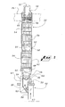
- FIG. 1 the general structure of a reactor pressure vessel (RPV) 10 is illustrated.
- the RPV 10 includes a reactor pressure vessel head 20, a steam dryer 22, a steam separator 24, a top guide 26, a core shroud 28, a core support plate 30, fuel assemblies 32, control rods 34, fuel support members 36, control rod guide tube 38, a lower plenum 40, reinforcing beams 42, recirculation pumps 44, and main steam lines 46.
- Coolant flow F cools the components of the RPV 10.
- Coolant e.g., water
- the coolant is heated to produce a two-phase flow including steam and liquid components.
- the steam and liquid components are separated from the flow by the reactor systems including the steam separators 24 and the steam dryers 22.
- steam is separated from the coolant flow by the steam separators 24 and then directed into the steam dryers 22 to remove additional moisture that may remain.
- pressurized steam is produced that is now directed by way of the main steam line 46 into the reactor's turbine building (not shown).
- the pressurized steam that has been generated is then directed into the turbine. Water that is separated from the flow by the steam separators 24 and the steam dryers 22 is redirected back down and into the recirculation pumps 44.
- the upper ends of the fuel assemblies 32 are supported by the top guide 26 and the lower ends of the fuel assemblies 32 are supported by the fuel support members 36.
- the fuel support member 36 is configured so as to support four fuel assemblies 32 in a lattice arrangement and to direct coolant flow from the lower plenum 40 upwards and into each of the four nuclear fuel assemblies 32, individually.
- the fuel support member 36 is inserted into the upper end of the control rod guide tube 38 so as to be positioned at the upper end of the control rod guide tube 38.
- the fuel assembly 32 includes a hollow metal channel 50, expansion springs 51, full length fuel rods 52, part-length fuel rods 53, fuel spacers 54, water rods 55, an upper tie plate 56 with a handle 57, and a lower tie plate 58.
- the hollow metal channel 50 has an elongated shape with a square cross-section and upper and lower open ends in which the upper tie plate 56 and lower tie plate 58 are received.
- the full length fuel rods 52 and the part-length fuel rods 53 are arranged in parallel and contain fissionable material.
- the fuel spacers 54 support both the full length fuel rods 52, the part-length fuel rods 53, and the water rods 55 at several positions along the entire length of the fuel assembly once the assembly is placed within the hollow metal channel 50.
- the upper and lower tie plates 56, 58 secure the upper and the lower ends of the full length fuel rods 52, while the lower ends of the part-length rods 53 are secured only to the lower tie plate 58. This assembly ensures that the coolant can pass through and around each of the fuel rods 52 and 53.
- the fuel assembly 32 may also include at least one water rod 55.
- the hollow metal channel 50 is vertical within the reactor's core, the upper tie plate 56 is positioned at the top opening of the hollow metal channel 50, which contains the components of each fuel assembly 32.
- the lower tie plate 58 is positioned at the bottom opening of the hollow metal channel 50, and the fuel spacers 54 are positioned at various locations along the interior length of the hollow metal channel 50.
- the fuel spacers 54 and the tie plates 56, 58 are configured so as to allow coolant flow through the fuel assembly 32.
- coolant flows in the flow direction F through the lower tie plate 58, over the fuel rods 52 and 53, along the interior length of the hollow metal channel 50 and then out through the top of the upper tie plate 56. Debris from reactor 10 systems can be entrained in the coolant flow and introduced to the fuel assembly 32 during normal operation.
- the lower tie plate 58 includes an inlet nozzle 60 that leads to a lower tie plate cavity 62, in which a filter cartridge 63 is disposed below a lower tie plate grid 64.
- the lower tie plate grid 64 is located at an upper end of the lower tie plate cavity 62 and supports the lower end plugs for the fuel rods 52 and 53.
- the lower tie plate grid 64 directs the flow of coolant into the fuel assemblies 32 and between all of the fuel rods 52 and 53 and the water rods 55.
- the lower tie plate 58 further includes a bail 59, which extends outward and across the inlet nozzle 60.
- the bail 59 is configured to facilitate directing the lower end of the lower tie plate 58 of the fuel assembly 32 so as to be received by the fuel support member 36.
- the fuel support member 36 includes a lower side entry orifice 82 that is configured to direct flow F from the lower plenum 40, upwards and through the support chamber 80 and into the fuel assembly 32.
- the support chamber 80 leads from a lower side entry orifice 82 where direct flow F enters from below.
- the bail 59 When the lower tie plate 58 is received within the support chamber 80, the bail 59 extends into the conical portion of the support chamber 80 through the receiving orifice 84.
- the outer inclined surface of the lower tie plate 58 forms a mechanical seal against a lip of the receiving orifice 84.
- the support chamber 80, the lower tie plate 58, and the hollow metal channel 50 provide a substantially continuous channel that directs the coolant flow from the lower plenum 40 through the support chamber 80 and upwards through the fuel assembly 32 resting atop of each fuel support 36.
- an exemplary prior art debris filter cartridge 67 (shown in FIGs. 4 and 5 ) is a single stage filter system that is positioned across the coolant flow F as it enters the inlet nozzle 60 of the lower tie plate, moves through the housing 62, and exits through the lower tie plate grid 64.
- the debris filter 67 may function well under steady flow conditions to impede debris from migrating into the fuel assembly, but if flow ceases or reverses, the debris can escape and become mobile again. Also, flow resistance may divert some backwater down through the inlet nozzle 60, allowing debris to evade filtration.
- the exemplary debris retention assembly 63 is at least a dual stage entrapment system that includes a debris filter 65 and debris retention device 66.
- FIG. 7 is an exploded cross-sectional view of a lower tie plate 58 with a fully assembled debris retention assembly 63 for a nuclear fuel assembly 32.
- the debris retention device 66 contains a debris tray 68, which is defined in part by a peripheral band 93 and one or more straining plates 92 interrupted by dead zones 70 (see FIG. 12 ).
- the straining plates 92 which may be integral to the peripheral band 93, have perforations 78 in certain embodiments, as will be discussed.
- the debris retention device 66 is further defined by a forward flow channel 90 that provides structure to the debris retention assembly 63, resists reverse flow of debris, and adds additional filtering capability, without adversely impacting performance in forward flow conditions.
- a peripheral band 93 encompasses all of these components as it defines the walls of the debris retention assembly 63.
- the peripheral band 93 has an outer surface that may be contoured with features, such as raised detents 72, which aid positioning, stability, and retention within the lower tie plate 58.
- the illustrated debris retention assembly 63 is configured to be inserted through a slot 74 and positioned within the lower tie plate cavity 62 between the inlet nozzle 60 and the lower tie plate grid 64.
- an existing fuel assembly can be retrofitted with a debris retention assembly 63, and that a debris retention assembly 63 can be removed and cleaned or replaced during maintenance operations.
- a machined metal cover plate 69 is used to seal slot 74 into which the filter cartridge is first inserted and also used to further maintain the debris retention assembly 63 positioning within the lower tie plate 58. Referring to FIGs.
- depressions (not shown) in the interior casting of the lower tie plate 58 correspond to detents 72 that protrude from one or more edges P along the periphery of the debris retention assembly 63.
- the detents 72 are configured to be received in the depressions to locate and secure the debris retention assembly 63 in position.
- the inside wall of the housing 62 that houses the debris retention assembly 63 within a lower tie plate 58 is cast larger than most conventional designs, to achieve desired flow dynamics. Specifically, the high velocity of the flow through the inlet nozzle 60 encountering the relatively sudden area expansion in the enlarged housing 62 creates a jet impingement flow pattern that direct debris towards low flow zones Z around the inner periphery of the lower tie plate cavity 62. The low flow zones Z within the debris retention assembly 63 are less extensive than the low flow zones Z that would exist inside the lower tie plate 58 in the absence of the debris retention assembly 63. FIG.
- FIG. 5 shows a cross-sectional diagram showing the housing 62 as enlarged in accordance with this aspect of certain embodiments, but with a prior art debris filter cartridge 67 installed within a lower tie plate 58, to demonstrate the pattern of vortices that are created by jet impingement of the coolant flow F on the filter cartridge 67.
- Low flow zones Z are created as the direct coolant flow F moves through the enlarged housing 62. Debris particles accumulate on surfaces 61 in the low flow zone Z.
- FIG. 7 illustrates an exploded view of the same housing 62 with an exemplary debris retention assembly 63
- FIG. 8 shows the debris retention assembly in operation in the housing 62.
- the central forward flow channel 90 allows coolant flow F to enter the debris retention assembly 63 in an unobstructed, relatively linear path and does not substantially change the direction or momentum of the coolant flow F. Any openings in the forward flow channel 90 are much coarser by design, as compared to the size of openings in the debris filter 65. Consequently, forward coolant flow F may be sufficiently forceful to propel debris D through the forward flow channel 90 where the debris D then encounters and is impeded by the debris filter 65. Under stagnant or reverse flow R/F conditions, however, the forward flow channel 90 impedes the release of debris from the debris retention assembly 63, as these conditions generally do not generate sufficient force to propel the debris back through the forward flow channel 90.
- the forward flow channel 90 impedes backwash flow and the escape of debris D from the debris retention cavity 76 of the debris retention assembly 63, without substantially impacting normal flow dynamics within the lower tie plate cavity 62.
- this backwash restrictive functionality can be achieved as shown in FIG. 9 , wherein the forward flow channel 90 includes a matrix of cylindrical cells 94 that resist backwash and divert debris D to the periphery of the cavity 76 to be captured by the straining plates 92.
- each cell 94 has a hexagonal cross-sectional shape, although other shapes may be suitable.
- the height, size, and thickness of the cells 94 is selected to allow linear flow (i.e., flow normal to the plane of forward flow channel 90) to pass unimpeded.
- the cylindrical cells in the forward flow channel 90 may be replaced with apertures (not shown) the diameter of which is small enough to stop low velocity debris D but large enough to have negligible impact on flow of coolant under any conditions.
- low flow zones Z are areas of low velocity, reverse flow R/F in the enlarged cavity 62 and are created at least in part by the vortices that naturally exist in the lower tie plate 58.
- the low flow zone is a volume where debris D that is blocked by the debris filter 65 can be collected in the straining plates 92 of the debris retention device 66.
- the debris retention device 66 includes forward flow channel 90 that allows coolant flow F to flow substantially unobstructed into the debris retention device 66, and straining plates 92 that are positioned to extend at least partially across the low flow zones Z. Due to flow impingement, debris D ( FIG. 11 ) propelled by the flow will be directed to the low flow zone Z resulting in an optimal position for the debris retention assembly 63.
- the forward flow channel 90 geometries FIGs. 9 and 12 ) inhibit local flow and allow the entrapment of debris, preventing its release under stagnant, forward flow, and reverse flow conditions.
- the dead zones 70 attract the debris as the sections with fine perforations 78 allow any back- water to cycle out of the cavity 76 without carrying the debris away.
- the perforations 78 in the debris retention cavity 76 may be directed to enhance the flushing characteristics of the debris off the surfaces 61, within the low flow zone Z, that accumulates within the cavity 62 of the lower tie plate 58 (see FIG. 8 ).
- coolant flows in direction F through the inlet nozzle 60, into the enlarged housing 62, through the debris retention assembly 63, and through the lower tie plate grid 64 before entering the fuel assembly 32.
- Debris passes into the debris retention assembly 63 through the forward flow channel 90 of the debris retention device 66 and is blocked by the debris filter 65 before the debris can enter the fuel assembly 32 and damage fuel rods 52 and 53.
- the flow impingement at the surface of the debris filter 65 pushes the debris to the low flow zones Z in the interior of the debris retention assembly 63.
- the debris falls into the straining plates 92 of the debris retention device 66 that is positioned within the low flow zone Z.
- Debris that is impeded and that is held by the flow F proximate the center of the debris filter 65 may fall to the debris retention device 66 during stagnant or reverse flow, also known as a "backwash,” such as when the fuel assembly 32 is moved.
- the forward flow channel 90 resists the release of debris under backwash.
- the debris filter 65 and the debris retention device 66 can alternatively be separate devices that are installed in series within the lower tie plate housing. In such embodiments, individual components can be interchanged or replaced separately.
Landscapes
- Physics & Mathematics (AREA)
- Engineering & Computer Science (AREA)
- Plasma & Fusion (AREA)
- General Engineering & Computer Science (AREA)
- High Energy & Nuclear Physics (AREA)
- Structure Of Emergency Protection For Nuclear Reactors (AREA)
- Filtration Of Liquid (AREA)
Claims (9)
- Trümmerrückhalteanordnung (63) für eine Brennstoffanordnung (32), die Folgendes aufweist:einen Trümmerfilter (65), der angepasst ist, um über einem Flussweg für Kühlmittel in die Brennstoffanordnung (32) angeordnet zu werden, wobei der Trümmerfilter (65) Filteröffnungen aufweist, die konfiguriert sind, um den Fluss von Trümmern in die Brennstoffanordnung (32) zu behindern; undeine Trümmerrückhaltevorrichtung (66), die konfiguriert ist, um stromaufwärts vom Trümmerfilter (65) in Bezug auf eine Vonrvärtsrichtung des Flusses positioniert zu werden, und angepasst ist, um entlang des Flusswegs angeordnet zu werden;
wobei die Trümmerrückhaltevorrichtung (66) einen zentralen Vorwärtsflusskanal (90) aufweist, der wirksam ist, um Kühlmittelfluss durch diese zu erlauben, um auf den Trümmerfilter (65) zu treffen, wobei der zentrale Vorwärtsflusskanal (90) eine oder mehrere Kanalöffnungen aufweist, die verglichen mit den Filteröffnungen in der Größe gröber sind, wobei die Trümmerrückhaltevorrichtung (66) ferner Folgendes aufweist:mindestens eine Siebplatte (92), die konfiguriert ist, um Trümmer zurückzuhalten, wobei die mindestens eine Siebplatte (92) den zentralen Vorwärtsflusskanal (90) umschließt, wobei die Trümmerrückhaltevorrichtung konfiguriert ist, um Trümmer zurückzuhalten, die vom Trümmerfilter (65) behindert wurden, um den Ausbruch der Trümmer aus der Trümmerrückhalteanordnung (63) zu verhindern;dadurch gekennzeichnet, dass: die Trümmerrückhalteanordnung ferner eine Einfassung aufweist, die den Trümmerfilter (65) und die Trümmerrückhaltevorrichtung (66) miteinander verbindet und ferner Wände eines Trümmerrückhalteholraums (76) definiert; wobei der Trümmerrückhalteholraum zwischen dem Trümmerfilter (65) und der Trümmerrückhaltevorrichtung (66) definiert ist; wobei die Trümmerrückhalteanordnung (63) konfiguriert ist, um durch einen Schlitz (74) einer unteren Bindeplatte (58) der Brennstoffanordnung (32) zum Positionieren innerhalb eines Bindeplattenhohlraums (62) der Brennstoffanordnung (32) eingeführt zu werden. - Trümmerrückhalteanordnung gemäß Anspruch 1, wobei die mindestens eine Siebplatte (92) eine Vielzahl von gelochten Siebplatten (92) mit mindestens einer Totzone (70) aufweist, die zwischen den Siebplatten (92) definiert ist, wobei jede Totzone (70) konfiguriert ist, um im Wesentlichen gegenüber dem Fluss des Kühlmittels undurchlässig zu sein.
- Trümmerrückhalteanordnung gemäß einem der Ansprüche 1 oder 2, wobei der Vorwärtsflusskanal (90) konfiguriert ist, um durch den Vorwärtsflusskanal (90) Kühlmittel zu transportieren, das in eine Richtung fließt, die im Wesentlichen zur Ebene des Vorwärtsflusskanals (90) normal ist, und Fluss des Kühlmittels zu widerstehen, der im Wesentlichen zur Ebene des Vorwärtsflusskanals (90) tangential ist.
- Trümmerrückhalteanordnung gemäß einem der Ansprüche 1 bis 3, wobei die mindestens eine Siebplatte (92) integral zu einem peripheren Band (93) ist, das nahe der Begrenzung eines inneren Hohlraums verläuft, der zwischen der Trümmerrückhaltevorrichtung (66) und dem Trümmerfilter (65) definiert ist.
- Trümmerrückhalteanordnung gemäß Anspruch 4, wobei:die mindestens eine Siebplatte (92) integral zu einem peripheren Band (93) ist, das nahe der Begrenzung eines inneren Hohlraums (76) verläuft, der zwischen der Trümmerrückhaltevorrichtung (66) und dem Trümmerfilter (65) definiert ist;das periphere Band (93) um den Vorwärtsflusskanal (90) herum verläuft, der im Zentrum des Flussweges angeordnet ist; undder Vorwärtsflusskanal (90) konfiguriert ist, um Trümmer unter stagnierenden und rückspülenden Bedingungen zurückzuhalten.
- Trümmerrückhalteanordnung gemäß Anspruch 5, wobei der Vorwärtsflusskanal (90) eine Matrix von Zylindern (94) einschließt.
- Trümmerrückhalteanordnung gemäß Anspruch 5, wobei die eine oder mehreren Kanalöffnungen des Vorwärtsflusskanals (90) sechseckig sind.
- Untere Bindeplatte (58) für eine Brennstoffanordnung, die Folgendes aufweist:eine Einlaufdüse (60) zum Aufnehmen von Kühlmittel in der Brennstoffanordnung (32) entlang eines Flussweges;ein Gehäuse (62), das in Bezug auf die Einlaufdüse (60) nach außen expandiert, um einen unteren Bindeplattenhohlraum (62) zu definieren;einen Schlitz (74);eine Trümmerrückhalteanordnung (63) gemäß einem der vorhergehenden Ansprüche;wobei die Trümmerrückhalteanordnung (63) konfiguriert ist, um durch den Schlitz (74) eingeführt zu werden, um innerhalb des unteren Bindeplattenhohlraums (62) positioniert zu werden.
- Untere Bindeplatte gemäß Anspruch 8, wobei der Trümmerrückhalteholraum niedrige Flusszonen neben dem Flussweg enthält.
Applications Claiming Priority (1)
| Application Number | Priority Date | Filing Date | Title |
|---|---|---|---|
| US13/026,940 US8611488B2 (en) | 2011-02-14 | 2011-02-14 | Debris exclusion and retention device for a fuel assembly |
Publications (3)
| Publication Number | Publication Date |
|---|---|
| EP2487690A2 EP2487690A2 (de) | 2012-08-15 |
| EP2487690A3 EP2487690A3 (de) | 2013-09-11 |
| EP2487690B1 true EP2487690B1 (de) | 2015-04-15 |
Family
ID=45562244
Family Applications (1)
| Application Number | Title | Priority Date | Filing Date |
|---|---|---|---|
| EP12154999.2A Active EP2487690B1 (de) | 2011-02-14 | 2012-02-10 | Vorrichtung zur Ausscheidung und Rückhaltung von Ablagerungen für eine Brennstoffanordnung |
Country Status (4)
| Country | Link |
|---|---|
| US (1) | US8611488B2 (de) |
| EP (1) | EP2487690B1 (de) |
| JP (1) | JP5789202B2 (de) |
| ES (1) | ES2538701T3 (de) |
Cited By (3)
| Publication number | Priority date | Publication date | Assignee | Title |
|---|---|---|---|---|
| RU2610716C1 (ru) * | 2015-12-09 | 2017-02-15 | Публичное акционерное общество "Машиностроительный завод" | Фильтр для тепловыделяющей сборки ядерного реактора |
| RU2610913C1 (ru) * | 2016-03-17 | 2017-02-17 | Публичное акционерное общество "Машиностроительный завод" | Тепловыделяющая сборка ядерного реактора |
| TWI723181B (zh) * | 2016-09-06 | 2021-04-01 | 瑞典商西屋電器瑞典股份有限公司 | 燃料總成 |
Families Citing this family (8)
| Publication number | Priority date | Publication date | Assignee | Title |
|---|---|---|---|---|
| US10176897B2 (en) * | 2014-01-13 | 2019-01-08 | Yousef M. Farawila | Floating filter screen in a lower tie plate box of a nuclear fuel assembly |
| CN104538064B (zh) * | 2014-12-19 | 2017-05-31 | 上海核工程研究设计院 | 一种平衡堆芯入口冷却剂流量的燃料组件下管座 |
| CN109863564B (zh) * | 2016-09-06 | 2023-03-10 | 西屋电器瑞典股份有限公司 | 燃料组件 |
| US10923237B2 (en) * | 2017-08-28 | 2021-02-16 | Global Nuclear Fuel—Americas, LLC | Debris filters for nuclear fuel assembly and method of using the same |
| EP4239650A1 (de) * | 2022-03-03 | 2023-09-06 | Westinghouse Electric Sweden AB | Filter zum abscheiden von partikeln aus einer kühlflüssigkeit in einem kernkraftwerk, filteranordnung und brennstabbündel |
| FR3140703B1 (fr) * | 2022-10-07 | 2025-06-20 | Framatome Sa | Filtre anti-débris pour embout inférieur d’assemblage de combustible nucléaire avec épaisseur variable |
| CN116538992B (zh) * | 2023-05-17 | 2025-08-22 | 西安交通大学 | 一种加压固化装药的药柱应变及壳体变形测量装置 |
| FR3164266A1 (fr) | 2024-07-02 | 2026-01-09 | Electricite De France | Ensemble de retenue de corps migrants pour un robinet à soupape en cours de maintenance et procédé pour sa mise en place |
Family Cites Families (13)
| Publication number | Priority date | Publication date | Assignee | Title |
|---|---|---|---|---|
| FR2646006B1 (fr) | 1989-04-12 | 1993-12-03 | Framatome | Embout inferieur d'un assemblage combustible comportant un dispositif de retenue de particules |
| ES2057652T3 (es) * | 1991-05-03 | 1994-10-16 | Siemens Ag | Elemento combustible de reactor de agua a presion con interceptor de fragmentos integrado en la parte de base. |
| US5483564A (en) | 1993-04-12 | 1996-01-09 | General Electric Company | Lower tie plate strainers including double corrugated strainers for boiling water reactors |
| US5390221A (en) * | 1993-08-23 | 1995-02-14 | General Electric Company | Debris filters with flow bypass for boiling water reactors |
| JPH08271672A (ja) * | 1995-03-31 | 1996-10-18 | Toshiba Corp | 流れ抵抗要素を備えた原子炉及び燃料集合体 |
| SE509687C2 (sv) * | 1996-12-20 | 1999-02-22 | Asea Atom Ab | Filter för en kärnbränslepatron |
| JPH11133176A (ja) * | 1997-08-29 | 1999-05-21 | Toshiba Corp | 燃料集合体 |
| SE521610C2 (sv) | 2001-01-22 | 2003-11-18 | Westinghouse Atom Ab | Filter och bränslepatron för en nukleär anläggning av lättvattentyp |
| JP2003232879A (ja) * | 2002-02-08 | 2003-08-22 | Toshiba Corp | 燃料支持金具及び燃料集合体 |
| US8317035B2 (en) * | 2004-12-30 | 2012-11-27 | Global Nuclear Fuel-Americas, Llc. | Debris filter |
| US8396182B2 (en) * | 2007-08-31 | 2013-03-12 | Global Nuclear Fuel—Americas, LLC | Method and apparatus to shield a nuclear fuel assembly with removable debris shield in upper tie |
| US20090060114A1 (en) * | 2007-08-31 | 2009-03-05 | Global Nuclear Fuel - Americas, Llc | Debris shield for upper tie plate in a nuclear fuel bundle and method for filtering debris |
| KR20120107453A (ko) * | 2009-06-23 | 2012-10-02 | 아토믹 에너지 오브 캐나다 리미티드 | 날개식 여과 요소 |
-
2011
- 2011-02-14 US US13/026,940 patent/US8611488B2/en active Active - Reinstated
-
2012
- 2012-02-08 JP JP2012024603A patent/JP5789202B2/ja active Active
- 2012-02-10 ES ES12154999.2T patent/ES2538701T3/es active Active
- 2012-02-10 EP EP12154999.2A patent/EP2487690B1/de active Active
Cited By (4)
| Publication number | Priority date | Publication date | Assignee | Title |
|---|---|---|---|---|
| RU2610716C1 (ru) * | 2015-12-09 | 2017-02-15 | Публичное акционерное общество "Машиностроительный завод" | Фильтр для тепловыделяющей сборки ядерного реактора |
| RU2610913C1 (ru) * | 2016-03-17 | 2017-02-17 | Публичное акционерное общество "Машиностроительный завод" | Тепловыделяющая сборка ядерного реактора |
| TWI723181B (zh) * | 2016-09-06 | 2021-04-01 | 瑞典商西屋電器瑞典股份有限公司 | 燃料總成 |
| US11075014B2 (en) | 2016-09-06 | 2021-07-27 | Westinghouse Electric Sweden Ab | Filter zones with different filtering efficiencies for a fuel assembly of a nuclear water reactor |
Also Published As
| Publication number | Publication date |
|---|---|
| JP2012177692A (ja) | 2012-09-13 |
| EP2487690A3 (de) | 2013-09-11 |
| US8611488B2 (en) | 2013-12-17 |
| EP2487690A2 (de) | 2012-08-15 |
| ES2538701T3 (es) | 2015-06-23 |
| US20120207262A1 (en) | 2012-08-16 |
| JP5789202B2 (ja) | 2015-10-07 |
Similar Documents
| Publication | Publication Date | Title |
|---|---|---|
| EP2487690B1 (de) | Vorrichtung zur Ausscheidung und Rückhaltung von Ablagerungen für eine Brennstoffanordnung | |
| US5483564A (en) | Lower tie plate strainers including double corrugated strainers for boiling water reactors | |
| JP5607288B2 (ja) | 破片ガイドを有する核燃料スペーサアセンブリ | |
| US5390221A (en) | Debris filters with flow bypass for boiling water reactors | |
| EP0184219B1 (de) | Teilchenabscheider für Kernbrennelementbundel | |
| JP5778883B2 (ja) | 核燃料バンドル中の上部タイプレート用のデブリシールドおよびデブリをフィルタにかける方法 | |
| EP0656630A1 (de) | Sieb mit versetzten Öffnungen versehener Doppelplatte für untere Halteplatte in Siedewasserreaktoren | |
| US5384814A (en) | Lower tie plate strainers for boiling water reactors | |
| TWI734492B (zh) | 核能燃料總成底部噴嘴之碎屑過濾配置及包含其之底部噴嘴 | |
| JP5712285B2 (ja) | 多重様式のデブリトラップおよび同一物を用いてデブリを分離する方法 | |
| CN110537229B (zh) | 核燃料组件碎屑过滤底部喷嘴 | |
| CN111095431A (zh) | 核反应堆燃料组件 | |
| EP0690453B1 (de) | Filter für Siedewasserkernreaktorbrennstabbündel | |
| KR101730678B1 (ko) | 고효율 스트레이너 시스템 | |
| KR20200089347A (ko) | 적층된 항공기 익형구조를 활용하여 유로홀을 형성한 핵연료 집합체의 하단고정체 | |
| KR101826045B1 (ko) | 삽입형 이물질여과장치를 가지는 핵연료집합체의 하단고정체 | |
| JP2000284080A (ja) | 沸騰水型原子炉用燃料集合体 | |
| JP2004523762A (ja) | 軽水炉のためのフィルタおよび燃料アセンブリ | |
| KR102162013B1 (ko) | 나선형 유로홀을 형성한 핵연료 집합체의 하단고정체 | |
| JPH09166675A (ja) | 燃料集合体及びデブリフィルター並びに下部タイプレート | |
| JP4282785B2 (ja) | 燃料集合体 | |
| CN120900273A (zh) | 一种紧凑型过滤器 | |
| JPH10213691A (ja) | 核燃料集合体 | |
| KR102656311B1 (ko) | 연료 집합체 | |
| JP2003232879A (ja) | 燃料支持金具及び燃料集合体 |
Legal Events
| Date | Code | Title | Description |
|---|---|---|---|
| PUAI | Public reference made under article 153(3) epc to a published international application that has entered the european phase |
Free format text: ORIGINAL CODE: 0009012 |
|
| AK | Designated contracting states |
Kind code of ref document: A2 Designated state(s): AL AT BE BG CH CY CZ DE DK EE ES FI FR GB GR HR HU IE IS IT LI LT LU LV MC MK MT NL NO PL PT RO RS SE SI SK SM TR |
|
| AX | Request for extension of the european patent |
Extension state: BA ME |
|
| RIN1 | Information on inventor provided before grant (corrected) |
Inventor name: LUCIANO, GERALD A. Inventor name: LONGREN, RICHARD C. Inventor name: SMITH, DAVID GREY Inventor name: DILLER, PETER RAY |
|
| PUAL | Search report despatched |
Free format text: ORIGINAL CODE: 0009013 |
|
| AK | Designated contracting states |
Kind code of ref document: A3 Designated state(s): AL AT BE BG CH CY CZ DE DK EE ES FI FR GB GR HR HU IE IS IT LI LT LU LV MC MK MT NL NO PL PT RO RS SE SI SK SM TR |
|
| AX | Request for extension of the european patent |
Extension state: BA ME |
|
| RIC1 | Information provided on ipc code assigned before grant |
Ipc: G21C 3/32 20060101ALI20130807BHEP Ipc: G21C 3/33 20060101ALI20130807BHEP Ipc: G21C 3/30 20060101AFI20130807BHEP |
|
| 17P | Request for examination filed |
Effective date: 20140311 |
|
| RBV | Designated contracting states (corrected) |
Designated state(s): AL AT BE BG CH CY CZ DE DK EE ES FI FR GB GR HR HU IE IS IT LI LT LU LV MC MK MT NL NO PL PT RO RS SE SI SK SM TR |
|
| 17Q | First examination report despatched |
Effective date: 20140402 |
|
| GRAP | Despatch of communication of intention to grant a patent |
Free format text: ORIGINAL CODE: EPIDOSNIGR1 |
|
| INTG | Intention to grant announced |
Effective date: 20141023 |
|
| GRAS | Grant fee paid |
Free format text: ORIGINAL CODE: EPIDOSNIGR3 |
|
| GRAA | (expected) grant |
Free format text: ORIGINAL CODE: 0009210 |
|
| AK | Designated contracting states |
Kind code of ref document: B1 Designated state(s): AL AT BE BG CH CY CZ DE DK EE ES FI FR GB GR HR HU IE IS IT LI LT LU LV MC MK MT NL NO PL PT RO RS SE SI SK SM TR |
|
| REG | Reference to a national code |
Ref country code: GB Ref legal event code: FG4D Ref country code: CH Ref legal event code: EP |
|
| REG | Reference to a national code |
Ref country code: IE Ref legal event code: FG4D |
|
| REG | Reference to a national code |
Ref country code: AT Ref legal event code: REF Ref document number: 722370 Country of ref document: AT Kind code of ref document: T Effective date: 20150515 |
|
| REG | Reference to a national code |
Ref country code: DE Ref legal event code: R096 Ref document number: 602012006625 Country of ref document: DE Effective date: 20150528 |
|
| REG | Reference to a national code |
Ref country code: SE Ref legal event code: TRGR Ref country code: ES Ref legal event code: FG2A Ref document number: 2538701 Country of ref document: ES Kind code of ref document: T3 Effective date: 20150623 |
|
| REG | Reference to a national code |
Ref country code: NL Ref legal event code: VDEP Effective date: 20150415 |
|
| REG | Reference to a national code |
Ref country code: AT Ref legal event code: MK05 Ref document number: 722370 Country of ref document: AT Kind code of ref document: T Effective date: 20150415 |
|
| REG | Reference to a national code |
Ref country code: LT Ref legal event code: MG4D |
|
| PG25 | Lapsed in a contracting state [announced via postgrant information from national office to epo] |
Ref country code: NL Free format text: LAPSE BECAUSE OF FAILURE TO SUBMIT A TRANSLATION OF THE DESCRIPTION OR TO PAY THE FEE WITHIN THE PRESCRIBED TIME-LIMIT Effective date: 20150415 |
|
| PG25 | Lapsed in a contracting state [announced via postgrant information from national office to epo] |
Ref country code: NO Free format text: LAPSE BECAUSE OF FAILURE TO SUBMIT A TRANSLATION OF THE DESCRIPTION OR TO PAY THE FEE WITHIN THE PRESCRIBED TIME-LIMIT Effective date: 20150715 Ref country code: PT Free format text: LAPSE BECAUSE OF FAILURE TO SUBMIT A TRANSLATION OF THE DESCRIPTION OR TO PAY THE FEE WITHIN THE PRESCRIBED TIME-LIMIT Effective date: 20150817 Ref country code: LT Free format text: LAPSE BECAUSE OF FAILURE TO SUBMIT A TRANSLATION OF THE DESCRIPTION OR TO PAY THE FEE WITHIN THE PRESCRIBED TIME-LIMIT Effective date: 20150415 Ref country code: HR Free format text: LAPSE BECAUSE OF FAILURE TO SUBMIT A TRANSLATION OF THE DESCRIPTION OR TO PAY THE FEE WITHIN THE PRESCRIBED TIME-LIMIT Effective date: 20150415 Ref country code: FI Free format text: LAPSE BECAUSE OF FAILURE TO SUBMIT A TRANSLATION OF THE DESCRIPTION OR TO PAY THE FEE WITHIN THE PRESCRIBED TIME-LIMIT Effective date: 20150415 |
|
| PG25 | Lapsed in a contracting state [announced via postgrant information from national office to epo] |
Ref country code: IS Free format text: LAPSE BECAUSE OF FAILURE TO SUBMIT A TRANSLATION OF THE DESCRIPTION OR TO PAY THE FEE WITHIN THE PRESCRIBED TIME-LIMIT Effective date: 20150815 Ref country code: GR Free format text: LAPSE BECAUSE OF FAILURE TO SUBMIT A TRANSLATION OF THE DESCRIPTION OR TO PAY THE FEE WITHIN THE PRESCRIBED TIME-LIMIT Effective date: 20150716 Ref country code: RS Free format text: LAPSE BECAUSE OF FAILURE TO SUBMIT A TRANSLATION OF THE DESCRIPTION OR TO PAY THE FEE WITHIN THE PRESCRIBED TIME-LIMIT Effective date: 20150415 Ref country code: AT Free format text: LAPSE BECAUSE OF FAILURE TO SUBMIT A TRANSLATION OF THE DESCRIPTION OR TO PAY THE FEE WITHIN THE PRESCRIBED TIME-LIMIT Effective date: 20150415 Ref country code: LV Free format text: LAPSE BECAUSE OF FAILURE TO SUBMIT A TRANSLATION OF THE DESCRIPTION OR TO PAY THE FEE WITHIN THE PRESCRIBED TIME-LIMIT Effective date: 20150415 |
|
| REG | Reference to a national code |
Ref country code: DE Ref legal event code: R097 Ref document number: 602012006625 Country of ref document: DE |
|
| PG25 | Lapsed in a contracting state [announced via postgrant information from national office to epo] |
Ref country code: EE Free format text: LAPSE BECAUSE OF FAILURE TO SUBMIT A TRANSLATION OF THE DESCRIPTION OR TO PAY THE FEE WITHIN THE PRESCRIBED TIME-LIMIT Effective date: 20150415 Ref country code: DK Free format text: LAPSE BECAUSE OF FAILURE TO SUBMIT A TRANSLATION OF THE DESCRIPTION OR TO PAY THE FEE WITHIN THE PRESCRIBED TIME-LIMIT Effective date: 20150415 |
|
| PLBE | No opposition filed within time limit |
Free format text: ORIGINAL CODE: 0009261 |
|
| STAA | Information on the status of an ep patent application or granted ep patent |
Free format text: STATUS: NO OPPOSITION FILED WITHIN TIME LIMIT |
|
| PG25 | Lapsed in a contracting state [announced via postgrant information from national office to epo] |
Ref country code: SK Free format text: LAPSE BECAUSE OF FAILURE TO SUBMIT A TRANSLATION OF THE DESCRIPTION OR TO PAY THE FEE WITHIN THE PRESCRIBED TIME-LIMIT Effective date: 20150415 Ref country code: PL Free format text: LAPSE BECAUSE OF FAILURE TO SUBMIT A TRANSLATION OF THE DESCRIPTION OR TO PAY THE FEE WITHIN THE PRESCRIBED TIME-LIMIT Effective date: 20150415 Ref country code: RO Free format text: LAPSE BECAUSE OF NON-PAYMENT OF DUE FEES Effective date: 20150415 Ref country code: CZ Free format text: LAPSE BECAUSE OF FAILURE TO SUBMIT A TRANSLATION OF THE DESCRIPTION OR TO PAY THE FEE WITHIN THE PRESCRIBED TIME-LIMIT Effective date: 20150415 |
|
| 26N | No opposition filed |
Effective date: 20160118 |
|
| PG25 | Lapsed in a contracting state [announced via postgrant information from national office to epo] |
Ref country code: IT Free format text: LAPSE BECAUSE OF FAILURE TO SUBMIT A TRANSLATION OF THE DESCRIPTION OR TO PAY THE FEE WITHIN THE PRESCRIBED TIME-LIMIT Effective date: 20150415 |
|
| PG25 | Lapsed in a contracting state [announced via postgrant information from national office to epo] |
Ref country code: BE Free format text: LAPSE BECAUSE OF NON-PAYMENT OF DUE FEES Effective date: 20160229 Ref country code: SI Free format text: LAPSE BECAUSE OF FAILURE TO SUBMIT A TRANSLATION OF THE DESCRIPTION OR TO PAY THE FEE WITHIN THE PRESCRIBED TIME-LIMIT Effective date: 20150415 |
|
| PG25 | Lapsed in a contracting state [announced via postgrant information from national office to epo] |
Ref country code: BE Free format text: LAPSE BECAUSE OF FAILURE TO SUBMIT A TRANSLATION OF THE DESCRIPTION OR TO PAY THE FEE WITHIN THE PRESCRIBED TIME-LIMIT Effective date: 20150415 |
|
| PG25 | Lapsed in a contracting state [announced via postgrant information from national office to epo] |
Ref country code: MC Free format text: LAPSE BECAUSE OF FAILURE TO SUBMIT A TRANSLATION OF THE DESCRIPTION OR TO PAY THE FEE WITHIN THE PRESCRIBED TIME-LIMIT Effective date: 20150415 Ref country code: LU Free format text: LAPSE BECAUSE OF FAILURE TO SUBMIT A TRANSLATION OF THE DESCRIPTION OR TO PAY THE FEE WITHIN THE PRESCRIBED TIME-LIMIT Effective date: 20160210 |
|
| REG | Reference to a national code |
Ref country code: CH Ref legal event code: PL |
|
| GBPC | Gb: european patent ceased through non-payment of renewal fee |
Effective date: 20160210 |
|
| PG25 | Lapsed in a contracting state [announced via postgrant information from national office to epo] |
Ref country code: CH Free format text: LAPSE BECAUSE OF NON-PAYMENT OF DUE FEES Effective date: 20160229 Ref country code: LI Free format text: LAPSE BECAUSE OF NON-PAYMENT OF DUE FEES Effective date: 20160229 |
|
| REG | Reference to a national code |
Ref country code: FR Ref legal event code: ST Effective date: 20161028 |
|
| REG | Reference to a national code |
Ref country code: IE Ref legal event code: MM4A |
|
| PG25 | Lapsed in a contracting state [announced via postgrant information from national office to epo] |
Ref country code: GB Free format text: LAPSE BECAUSE OF NON-PAYMENT OF DUE FEES Effective date: 20160210 Ref country code: IE Free format text: LAPSE BECAUSE OF NON-PAYMENT OF DUE FEES Effective date: 20160210 Ref country code: FR Free format text: LAPSE BECAUSE OF NON-PAYMENT OF DUE FEES Effective date: 20160229 |
|
| PG25 | Lapsed in a contracting state [announced via postgrant information from national office to epo] |
Ref country code: MT Free format text: LAPSE BECAUSE OF FAILURE TO SUBMIT A TRANSLATION OF THE DESCRIPTION OR TO PAY THE FEE WITHIN THE PRESCRIBED TIME-LIMIT Effective date: 20150415 |
|
| PG25 | Lapsed in a contracting state [announced via postgrant information from national office to epo] |
Ref country code: CY Free format text: LAPSE BECAUSE OF FAILURE TO SUBMIT A TRANSLATION OF THE DESCRIPTION OR TO PAY THE FEE WITHIN THE PRESCRIBED TIME-LIMIT Effective date: 20150415 Ref country code: HU Free format text: LAPSE BECAUSE OF FAILURE TO SUBMIT A TRANSLATION OF THE DESCRIPTION OR TO PAY THE FEE WITHIN THE PRESCRIBED TIME-LIMIT; INVALID AB INITIO Effective date: 20120210 Ref country code: SM Free format text: LAPSE BECAUSE OF FAILURE TO SUBMIT A TRANSLATION OF THE DESCRIPTION OR TO PAY THE FEE WITHIN THE PRESCRIBED TIME-LIMIT Effective date: 20150415 |
|
| PG25 | Lapsed in a contracting state [announced via postgrant information from national office to epo] |
Ref country code: MK Free format text: LAPSE BECAUSE OF FAILURE TO SUBMIT A TRANSLATION OF THE DESCRIPTION OR TO PAY THE FEE WITHIN THE PRESCRIBED TIME-LIMIT Effective date: 20150415 Ref country code: TR Free format text: LAPSE BECAUSE OF FAILURE TO SUBMIT A TRANSLATION OF THE DESCRIPTION OR TO PAY THE FEE WITHIN THE PRESCRIBED TIME-LIMIT Effective date: 20150415 Ref country code: MT Free format text: LAPSE BECAUSE OF FAILURE TO SUBMIT A TRANSLATION OF THE DESCRIPTION OR TO PAY THE FEE WITHIN THE PRESCRIBED TIME-LIMIT Effective date: 20160229 |
|
| PG25 | Lapsed in a contracting state [announced via postgrant information from national office to epo] |
Ref country code: BG Free format text: LAPSE BECAUSE OF FAILURE TO SUBMIT A TRANSLATION OF THE DESCRIPTION OR TO PAY THE FEE WITHIN THE PRESCRIBED TIME-LIMIT Effective date: 20150415 |
|
| PG25 | Lapsed in a contracting state [announced via postgrant information from national office to epo] |
Ref country code: AL Free format text: LAPSE BECAUSE OF FAILURE TO SUBMIT A TRANSLATION OF THE DESCRIPTION OR TO PAY THE FEE WITHIN THE PRESCRIBED TIME-LIMIT Effective date: 20150415 |
|
| PGFP | Annual fee paid to national office [announced via postgrant information from national office to epo] |
Ref country code: SE Payment date: 20260121 Year of fee payment: 15 |
|
| PGFP | Annual fee paid to national office [announced via postgrant information from national office to epo] |
Ref country code: ES Payment date: 20260302 Year of fee payment: 15 |
|
| PGFP | Annual fee paid to national office [announced via postgrant information from national office to epo] |
Ref country code: DE Payment date: 20260121 Year of fee payment: 15 |