EP2485846B1 - Methods, systems and apparatus for manipulating particles - Google Patents
Methods, systems and apparatus for manipulating particles Download PDFInfo
- Publication number
- EP2485846B1 EP2485846B1 EP10771586.4A EP10771586A EP2485846B1 EP 2485846 B1 EP2485846 B1 EP 2485846B1 EP 10771586 A EP10771586 A EP 10771586A EP 2485846 B1 EP2485846 B1 EP 2485846B1
- Authority
- EP
- European Patent Office
- Prior art keywords
- chamber
- conduit
- rotor
- inlet
- outlet
- Prior art date
- Legal status (The legal status is an assumption and is not a legal conclusion. Google has not performed a legal analysis and makes no representation as to the accuracy of the status listed.)
- Active
Links
- 239000002245 particle Substances 0.000 title claims description 32
- 238000000034 method Methods 0.000 title claims description 21
- 239000012530 fluid Substances 0.000 claims description 126
- 239000000463 material Substances 0.000 claims description 65
- 238000004891 communication Methods 0.000 claims description 45
- 238000004382 potting Methods 0.000 claims description 40
- 238000001125 extrusion Methods 0.000 claims description 28
- 230000007246 mechanism Effects 0.000 claims description 11
- 230000008878 coupling Effects 0.000 claims description 5
- 238000010168 coupling process Methods 0.000 claims description 5
- 238000005859 coupling reaction Methods 0.000 claims description 5
- 230000002401 inhibitory effect Effects 0.000 claims description 4
- 230000000007 visual effect Effects 0.000 claims description 4
- 230000003100 immobilizing effect Effects 0.000 claims description 2
- 239000007787 solid Substances 0.000 description 22
- 230000008569 process Effects 0.000 description 9
- 239000007788 liquid Substances 0.000 description 8
- 238000012545 processing Methods 0.000 description 7
- 230000008901 benefit Effects 0.000 description 6
- 238000011109 contamination Methods 0.000 description 6
- 238000012546 transfer Methods 0.000 description 6
- 241000237983 Trochidae Species 0.000 description 4
- 230000000712 assembly Effects 0.000 description 4
- 238000000429 assembly Methods 0.000 description 4
- 238000011072 cell harvest Methods 0.000 description 3
- 238000010586 diagram Methods 0.000 description 3
- 230000000694 effects Effects 0.000 description 3
- 239000012737 fresh medium Substances 0.000 description 3
- 239000004519 grease Substances 0.000 description 3
- 238000003306 harvesting Methods 0.000 description 3
- 229920000642 polymer Polymers 0.000 description 3
- 238000000926 separation method Methods 0.000 description 3
- 238000003466 welding Methods 0.000 description 3
- 229920006362 Teflon® Polymers 0.000 description 2
- 230000009471 action Effects 0.000 description 2
- 238000005452 bending Methods 0.000 description 2
- 239000008280 blood Substances 0.000 description 2
- 210000004369 blood Anatomy 0.000 description 2
- 238000004113 cell culture Methods 0.000 description 2
- 238000005119 centrifugation Methods 0.000 description 2
- 238000004140 cleaning Methods 0.000 description 2
- 238000012258 culturing Methods 0.000 description 2
- 238000011194 good manufacturing practice Methods 0.000 description 2
- 230000000670 limiting effect Effects 0.000 description 2
- 238000012986 modification Methods 0.000 description 2
- 230000004048 modification Effects 0.000 description 2
- 230000036961 partial effect Effects 0.000 description 2
- 230000010412 perfusion Effects 0.000 description 2
- 229920002635 polyurethane Polymers 0.000 description 2
- 239000004814 polyurethane Substances 0.000 description 2
- 230000002829 reductive effect Effects 0.000 description 2
- 238000001890 transfection Methods 0.000 description 2
- 239000002699 waste material Substances 0.000 description 2
- 230000003313 weakening effect Effects 0.000 description 2
- 229920000299 Nylon 12 Polymers 0.000 description 1
- 229910000831 Steel Inorganic materials 0.000 description 1
- 230000002776 aggregation Effects 0.000 description 1
- 238000004220 aggregation Methods 0.000 description 1
- 229910052782 aluminium Inorganic materials 0.000 description 1
- XAGFODPZIPBFFR-UHFFFAOYSA-N aluminium Chemical compound [Al] XAGFODPZIPBFFR-UHFFFAOYSA-N 0.000 description 1
- 239000012620 biological material Substances 0.000 description 1
- 238000009954 braiding Methods 0.000 description 1
- -1 but not limited to Polymers 0.000 description 1
- 230000008859 change Effects 0.000 description 1
- 239000011248 coating agent Substances 0.000 description 1
- 238000000576 coating method Methods 0.000 description 1
- 239000012141 concentrate Substances 0.000 description 1
- 238000010276 construction Methods 0.000 description 1
- 230000008602 contraction Effects 0.000 description 1
- 238000001816 cooling Methods 0.000 description 1
- 230000007812 deficiency Effects 0.000 description 1
- 230000001687 destabilization Effects 0.000 description 1
- 238000007599 discharging Methods 0.000 description 1
- 230000008030 elimination Effects 0.000 description 1
- 238000003379 elimination reaction Methods 0.000 description 1
- 229920005570 flexible polymer Polymers 0.000 description 1
- 238000005194 fractionation Methods 0.000 description 1
- 230000006870 function Effects 0.000 description 1
- 230000005484 gravity Effects 0.000 description 1
- 230000036512 infertility Effects 0.000 description 1
- 238000003780 insertion Methods 0.000 description 1
- 230000037431 insertion Effects 0.000 description 1
- 238000009434 installation Methods 0.000 description 1
- 229920001684 low density polyethylene Polymers 0.000 description 1
- 239000004702 low-density polyethylene Substances 0.000 description 1
- 239000002184 metal Substances 0.000 description 1
- 229910052751 metal Inorganic materials 0.000 description 1
- 238000010899 nucleation Methods 0.000 description 1
- 239000004033 plastic Substances 0.000 description 1
- 229920003023 plastic Polymers 0.000 description 1
- 102000004169 proteins and genes Human genes 0.000 description 1
- 108090000623 proteins and genes Proteins 0.000 description 1
- 238000000746 purification Methods 0.000 description 1
- 230000004044 response Effects 0.000 description 1
- 238000005070 sampling Methods 0.000 description 1
- 229910052710 silicon Inorganic materials 0.000 description 1
- 239000010703 silicon Substances 0.000 description 1
- 239000010959 steel Substances 0.000 description 1
- 230000001954 sterilising effect Effects 0.000 description 1
- 238000004659 sterilization and disinfection Methods 0.000 description 1
- 239000000126 substance Substances 0.000 description 1
- 230000007704 transition Effects 0.000 description 1
Images


Classifications
-
- B—PERFORMING OPERATIONS; TRANSPORTING
- B04—CENTRIFUGAL APPARATUS OR MACHINES FOR CARRYING-OUT PHYSICAL OR CHEMICAL PROCESSES
- B04B—CENTRIFUGES
- B04B5/00—Other centrifuges
- B04B5/04—Radial chamber apparatus for separating predominantly liquid mixtures, e.g. butyrometers
- B04B5/0442—Radial chamber apparatus for separating predominantly liquid mixtures, e.g. butyrometers with means for adding or withdrawing liquid substances during the centrifugation, e.g. continuous centrifugation
-
- B—PERFORMING OPERATIONS; TRANSPORTING
- B04—CENTRIFUGAL APPARATUS OR MACHINES FOR CARRYING-OUT PHYSICAL OR CHEMICAL PROCESSES
- B04B—CENTRIFUGES
- B04B15/00—Other accessories for centrifuges
-
- C—CHEMISTRY; METALLURGY
- C12—BIOCHEMISTRY; BEER; SPIRITS; WINE; VINEGAR; MICROBIOLOGY; ENZYMOLOGY; MUTATION OR GENETIC ENGINEERING
- C12M—APPARATUS FOR ENZYMOLOGY OR MICROBIOLOGY; APPARATUS FOR CULTURING MICROORGANISMS FOR PRODUCING BIOMASS, FOR GROWING CELLS OR FOR OBTAINING FERMENTATION OR METABOLIC PRODUCTS, i.e. BIOREACTORS OR FERMENTERS
- C12M33/00—Means for introduction, transport, positioning, extraction, harvesting, peeling or sampling of biological material in or from the apparatus
- C12M33/10—Means for introduction, transport, positioning, extraction, harvesting, peeling or sampling of biological material in or from the apparatus by centrifugation ; Cyclones
-
- B—PERFORMING OPERATIONS; TRANSPORTING
- B04—CENTRIFUGAL APPARATUS OR MACHINES FOR CARRYING-OUT PHYSICAL OR CHEMICAL PROCESSES
- B04B—CENTRIFUGES
- B04B5/00—Other centrifuges
- B04B5/04—Radial chamber apparatus for separating predominantly liquid mixtures, e.g. butyrometers
- B04B5/0442—Radial chamber apparatus for separating predominantly liquid mixtures, e.g. butyrometers with means for adding or withdrawing liquid substances during the centrifugation, e.g. continuous centrifugation
- B04B2005/0471—Radial chamber apparatus for separating predominantly liquid mixtures, e.g. butyrometers with means for adding or withdrawing liquid substances during the centrifugation, e.g. continuous centrifugation with additional elutriation separation of different particles
-
- B—PERFORMING OPERATIONS; TRANSPORTING
- B04—CENTRIFUGAL APPARATUS OR MACHINES FOR CARRYING-OUT PHYSICAL OR CHEMICAL PROCESSES
- B04B—CENTRIFUGES
- B04B5/00—Other centrifuges
- B04B5/04—Radial chamber apparatus for separating predominantly liquid mixtures, e.g. butyrometers
- B04B5/0442—Radial chamber apparatus for separating predominantly liquid mixtures, e.g. butyrometers with means for adding or withdrawing liquid substances during the centrifugation, e.g. continuous centrifugation
- B04B2005/0492—Radial chamber apparatus for separating predominantly liquid mixtures, e.g. butyrometers with means for adding or withdrawing liquid substances during the centrifugation, e.g. continuous centrifugation with fluid conveying umbilicus between stationary and rotary centrifuge parts
Definitions
- the present invention is related to methods, systems, and apparatus that are used for transferring and manipulating particles, as well as components that are useful in systems and apparatus for transferring and manipulating particles, such as continuous flow centrifuges.
- Umbilical-like arrangements for use with continuous flow centrifuges have been disclosed in, for example, U.S. Patent Nos. 4,216,770 , 4,419,089 , 4,389,206 , and 5,665,048 .
- these solutions do not adequately address the high stresses and strains imparted on the tubes due to the g-forces created by rotating the centrifuge at high speeds and/or due to the continuous fluid flow necessary to substantially immobilize particles.
- rotating the centrifuge at high speeds creates increased "partial" twisting action of the umbilical system and the tubes contained therein, and the arrangements disclosed to date do not allow the umbilical system and the tubes contained therein to be rotated at a high rate of speed for an acceptable amount of time before failing.
- the aforementioned solutions simply do not allow the systems to be "scaled up" to an appreciable degree and do not allow the system to be rotated at high rates of speed without rapid and catastrophic failure of the tubing system.
- the elimination of rotary seals or the like may address some contamination concerns with regard to conventional continuous flow centrifuges.
- the fluid flow paths may become contaminated over time ( e.g ., after more than one use), unless the utmost care is taken in cleaning and/or sterilization.
- a disposable fluid flow path (or multiple disposable fluid flow paths) could eliminate the need for expensive and time-consuming cleaning, and could help ensure contamination-free operations.
- the disposable fluid flow paths would preferably be easily replaceable, and would be adaptable to a system that would allow the system as a whole to be "scaled-up," as discussed above.
- US4056224 discloses a seal-less disposable flow system for use in conjunction with a centrifugal liquid processing apparatus or the like wherein a rotor assembly for subjecting a liquid to be processed to centrifugation is rotatably mounted on a rotor drive assembly, which is rotatably mounted to a stationary base.
- the rotor assembly is rotatably driven in the same direction as the rotor drive assembly with a speed ratio of 2: 1.
- the flow system includes two containers adapted for mounting on the rotor assembly and a flexible umbilical cable which extends from the containers to a location external to the apparatus by way of a passageway provided in the support shaft of the rotor assembly and guide means carried on and rotatably mounted to the rotor drive assembly to maintain liquid communication with the containers during rotation of the rotor without the use of rotating seals.
- a reusable leader assembly facilitates installation of the flow system in the processing apparatus.
- a centrifugal separator has a flexible member for the transport of liquid to and/or from a centrifuge rotor, which rotates around the rotor in the same direction but with half the speed.
- the flexible member is provided with a braided casing to give it a large stiffness against torsion, good tension strength and an outside surface with good wear resistance.
- the casing comprises plaited threads of e.g. metal or plastics, some of which extend helically with a certain pitch around the flexible member and others of which extend helically in the opposite direction.
- the plaiting of the threads is such that the casing per se is axially contractable and extensible with simultaneous radial expansion and contraction, respectively. When in use the casing is axially extended so that it is radially contracted into frictional engagement with the flexible member.
- WO 2009/062714 proposes an apparatus and a method for transferring energy and/or a substance from a non-rotating means of an apparatus to a rotating device - or vice versa - through the intermediary of a suitable means.
- US4372484 discloses an apparatus for separating a liquid, such as whole blood, into fractions having different densities includes a separation chamber and a transfer device, such as a continuous piece of flexible tubing, for supplying the liquid to the separation chamber and discharging the liquid fractions therefrom.
- the separation chamber and the transfer device are conjointly rotated about a first axis which passes through a stationary end of the transfer device, while being simultaneously and conjointly rotated about a second axis which is coincident with a medial longitudinal axis of the rotating end of the transfer device so as to prevent the transfer device from twisting as a result of its rotation about the first axis.
- Embodiments of the present invention provide an apparatus for manipulating particles, such as recited in claim 1.
- the first and second passageways for each chamber comprise corresponding first and second flexible tubes that extend through at least a major portion of a length of the conduit. Potting material within the conduit is configured to hold the tubes in the spaced-apart relationship relative to the one another and hold the tubes in a spaced-apart relationship relative to the conduit. The potting material may be further configured to restrict movement of the tubes relative to the conduit and/or restrict movement of the tubes relative to one another.
- the umbilical assembly further includes a flexible member extending through at least a major portion of a length of the conduit, wherein the flexible member extends substantially along a centerline of the conduit, and wherein the flexible tubes surround the flexible member.
- the potting material may be further configured to restrict movement of the tubes relative to the flexible member.
- Each chamber may be a flexible translucent or transparent fluid chamber
- the apparatus may further include at least one chamber holder pivotably mounted to the front side of the rotor, wherein each chamber holder is configured to releasably enclose a respective chamber.
- Each chamber holder may include a window to allow visual access to the enclosed chamber.
- Each chamber may include a substantially conical body portion and a flange extending about at least a portion of a perimeter of the conical body portion.
- the flange includes an inlet fluid path and an outlet fluid path, wherein the first flexible tube connects with the flange inlet fluid path of a respective chamber and the second flexible tube connects -with the flange outlet fluid path of the respective chamber.
- the flange inlet and outlet paths may be substantially parallel along a segment extending from a point at which the first and second tubes connect with the flange inlet and outlet paths.
- the conduit and passageways are integrated as a flexible extrusion with an outer wall and internal elongate channels that define the spaced- apart passageways.
- Each chamber may include a substantially conical body portion and a flange extending about at least a portion of a perimeter of the conical body portion.
- the flange includes an inlet fluid path and an outlet fluid path, wherein the first passageway is in fluid communication with the flange inlet fluid path of a respective chamber and the second passageway is in fluid communication with the flange outlet fluid path of the respective chamber.
- a first tube may connect the first passageway and the flange inlet fluid path and a second tube may connect the second passageway and the flange outlet fluid path, and the flange inlet and outlet paths may be substantially parallel along a segment extending from a point at which the first and second tubes connect with the flange inlet and outlet paths.
- a connector may be included at each of the first and second passageways, with one connector configured to connect the first tube with the first passageway and the other connector configured to connect the second tube with the second passageway.
- the drive mechanism may include gears.
- the gears may be at least partially enclosed by the drum.
- the conduit may include proximal and distal opposite ends, wherein the conduit distal end connects to the rotor.
- the conduit distal end has a substantially hexagonally shaped coupling.
- the umbilical assembly includes a plurality of spaced- apart flexible holders in the conduit to hold the passageways in the spaced-apart relationship.
- the at least one chamber comprises a plurality of chambers mounted on the rotor in a spaced-apart relationship.
- a disposable fluid path for use with a continuous flow centrifuge including a rotor having an outer periphery and front and rear opposite sides includes: at least one chamber mounted on the rotor, each chamber having an inlet and an outlet; a flexible conduit curving around the outer periphery of the rotor and connecting to the rotor; first and second flexible tubes for each chamber .extending through the conduit, wherein the first tube is in fluid communication with the inlet of a respective chamber and the second tube is in fluid communication with the outlet of the respective chamber; and potting material within the conduit, wherein the potting material is configured to hold the tubes in a spaced-apart relationship.
- the potting material may be further configured to restrict movement of the tubes relative to the conduit and/or relative to one another.
- the disposable fluid path further includes a flexible member extending through the conduit, wherein the flexible member extends substantially -along a centerline of the conduit, and wherein the flexible tubes surround the flexible member.
- the potting material may be further configured to restrict movement of the tubes relative to the flexible member.
- the potting material may be further configured to restrict movement of the tubes relative to the conduit and/or relative to one another.
- the umbilical assembly further includes a flexible member extending through the conduit, wherein the flexible member extends substantially along a centerline of the conduit, and wherein the flexible tubes surround the flexible member.
- the potting material may be further configured to restrict movement of the tubes relative to the flexible member.
- an umbilical assembly for use with a continuous flow centrifuge having a rotor and at least one chamber attached to the rotor includes a flexible extrusion comprising first and second spaced-apart passageways therein for each chamber, wherein the first passageway is in fluid communication with an inlet of a respective chamber and the second passageway is in fluid communication with an outlet of the respective chamber.
- a disposable fluid path for use with a continuous flow centrifuge having a rotor includes a first disposable section and a second disposable section.
- the first disposable section includes: at least one chamber configured to be held on the rotor, wherein each chamber has an inlet and an outlet; and first and second tubes for each chamber, wherein the first tube is configured to be in fluid communication with the inlet of a respective chamber and the second tube is configured to be in fluid communication with the outlet of the respective chamber.
- the second disposable section includes: tubing in fluid communication with at least one container; the tubing configured to fit within one or more valves.
- the first disposable section includes return tubing in fluid communication with the at least one container.
- the second disposable section includes return tubing in fluid communication with the at least one container.
- the first and second disposable sections may be configured to be connected using a sterile tube welding process.
- each chamber is a flexible translucent or transparent fluid chamber, wherein the chamber includes a substantially conical body portion.
- the chamber also includes a flange extending about at least a portion of a perimeter of the substantially conical body portion, and the flange includes an integral inlet fluid path and an integral outlet fluid path.
- the first tube connects with the flange inlet fluid path of a respective chamber and the second tube connects with the flange outlet fluid path of the respective chamber.
- the flange inlet and outlet fluid paths may be substantially parallel along a segment extending from the point at which the first and second tubes connect with the flange inlet and outlet fluid paths.
- a centrifugal fluid processing system includes: a housing having an interior cavity with an access aperture extending from an external surface of the housing to the interior cavity; a plurality of fluid chambers held in spaced apart relationship on a rotor in the interior cavity; a flexible conduit holding a plurality of flexible tubes in a spaced-apart relationship therein, the flexible conduit extending from a location that is external to the housing through the access aperture and into the interior cavity, wherein the plurality of tubes includes first and second tubes for each chamber, wherein the first tube is in fluid communication with an inlet of a respective chamber and the second tube is in fluid communication with an outlet of the respective chamber, wherein the flexible conduit comprises a solid flexible material that substantially fills an internal volume of the conduit and surrounds the flexible tubes, with the solid flexible material configured to hold the flexible tubes in the spaced-apart relationship; a substantially rigid curvilinear guide tube holding a portion of the flexible conduit in the interior cavity; and a drive mechanism configured to rotate the guide tube at a first speed and
- a centrifugal fluid processing system includes: a housing having an interior cavity with an access aperture extending from an external surface of the housing to the interior cavity; a plurality of fluid chambers held in spaced apart relationship on a rotor in the interior cavity; a flexible conduit including a plurality of spaced-apart passageways therein, the flexible conduit extending from a location that is external to the housing through the access aperture and into the interior cavity, wherein the plurality of tubes includes first and second passageways for each chamber, wherein the first passageway is in fluid communication with an inlet of a respective chamber and the second passageway is in fluid communication with an outlet of the respective chamber; a substantially funnel-shaped support with an open center passage, the support having a shape that tapers outward as it extends further into the interior cavity, wherein the support surrounds the flexible conduit with a centerline of the funnel shaped support being in line with a centerline of the access aperture; a substantially rigid curvilinear guide tube holding a portion of the flexible conduit in the interior cavity
- a centrifugal fluid processing system includes: a housing having an interior cavity with an access aperture extending from an external surface of the housing to the interior cavity; a plurality of flexible translucent or transparent fluid chambers having an inlet and an outlet held in spaced-apart relationship on a rotor in the interior cavity, wherein each chamber includes a substantially conical body portion, each chamber including a flange extending about at least a portion of a perimeter of the conical body portion, the flange including an inlet fluid path and an outlet fluid path, wherein the flange inlet fluid path is in fluid communication with the inlet of the chamber and the flange outlet fluid path is in fluid communication with the outlet of the chamber; a flexible conduit including a plurality of elongate spaced-apart passageways therein, the flexible conduit extending from a location that is external to the housing through the access aperture and into the interior cavity, wherein the plurality of passageways includes first and second passageways for each chamber, and wherein the first passageway is in fluid communication
- Embodiments of the present invention also provide a method of manipulating particles, such as recited in claim 14.
- the device may be otherwise oriented (rotated 90 degrees or at other orientations) and the spatially relative descriptors used herein interpreted accordingly.
- the terms “upwardly”, “downwardly”, “vertical”, “horizontal” and the like are used herein for the purpose of explanation only unless specifically indicated otherwise.
- Apparatus, systems, and methods for the manipulation of particles are disclosed herein. Also, components useful in apparatus and systems for the manipulation of particles are disclosed herein.
- FIGS 1 and 2 illustrate a system 10 according to some embodiments of the present invention.
- the system 10 includes an enclosure or housing 15 and a door 20.
- the door 20 provides access to the internal components of the system 10, which are described in more detail below.
- the door 20 may include a window 25 to provide visual access to the internal components.
- the door 20 can be hingedly attached to the enclosure 15, and can be opened by a handle 30, for example.
- the system 10 includes a flange 35 .
- the flange 35 may be included with the door 20 , or may be a separate component ( i.e ., when the door 20 is opened, the flange 35 remains in place).
- the flange 35 includes an access aperture 40 , through which conduit with channels, passageways, or tubing therein, for example, can extend, as described in more detail below.
- the door 20 and/or the flange 35 can include a clamp 42 , which is configured to hold the conduit in place and/or release the conduit.
- Figure 3 illustrates the system 10 with the door 20 opened. As shown, the flange 35 remains in place.
- Figure 4 illustrates the system 10 with the door 20 and the flange 35 pivotably opened.
- the enclosure or housing has an interior cavity 44 , which can be seen in Figures 3 and 4 when the door 20 and/or the flange 35 have been opened. Some of the internal components of the system 10 are contained in the interior cavity 44, as seen in Figures 3 and 4 .
- a rotor 45 is configured to be rotatable about an axis.
- At least one fluid chamber 50 is attached to or mounted on the rotor 45 , so as to be held in a fixed spaced-apart relationship and rotate in response to rotation of the rotor 45.
- a plurality of chambers 50 are attached to or mounted on the rotor 45 ; in the illustrated embodiment, four chambers 50 are present.
- the chamber 50 may be substantially cone-shaped or may include a substantially cone-shaped portion, as illustrated, although other shapes are contemplated including, for example, cylindrical, rectangular, frustoconical, pyramidal, etc.
- the chamber 50 includes an inlet 55 and an outlet 60 .
- the chamber 50 is typically attached to or mounted on the rotor 45 such that inlet 55 is situated toward the outer periphery of the rotor 45 , and the outlet 60 is typically situated toward the center of the rotor 45 (see Figure 6 ).
- the chamber 50 is configured to allow fluid flow therethrough while the rotor 45 and the chamber 50 rotate about an axis.
- the force of fluid flowing from the inlet 55 to the outlet 60 can substantially oppose a centrifugal force created by the rotation of the rotor 45 and the chamber 50 .
- particles can be substantially immobilized in the chamber 50 , such as in a fluidized bed in the chamber 50 , by use of the summation of forces acting on the particles. This action is described in more detail in U.S. Patent Nos. 5,622,819 ; 5,821,116 ; 6,133,019 ; 6,214,617 ; 6,334,842 ; 6,514,189 ; 6,660,509 ; 6,703,217 ; 6,916,652 ; 6,942,804 ; 7,029,430 ; and 7,347,943 ; and U.S. Patent Application Publication Nos. 2005/0266548 and 2008/0264865 .
- the rotor 45 may rotate in a plane substantially coaxial with the gravitational axis (i.e ., the rotor may rotate about a substantially horizontal axis). Particles are substantially immobilized within a fluidized bed within the chamber 50 by use of the summation of the vector forces acting on each particle.
- Embodiments of such apparatus have been disclosed in U.S. Patent Nos. 5,622,819 ; 5,821,116 ; 6,133,019 ; 6,214,617 ; 6,660,509 ; 6,703,217 ; 6,916,652 ;. 6,942,804 ; 7,347,943 ; and U.S. Patent Application Publication Nos. 2005/0266548 and 2008/0264865 .
- the rotor 45 may rotate in a plane substantially transverse to the gravitational axis. In this regard, the rotor 45 may rotate about a substantially vertical axis.
- Embodiments of such apparatus have been disclosed in U.S. Patent Nos. 4,939,087 ; 5,674,173 ; 5,722,926 ; 6,051,146 ; 6,071,422 ; 6,334,842 ; 6,354,986 ; 6,514,189 ; 7,029,430 ; 7,201,848 ; and 7,422,693 .
- Particles are substantially immobilized within a fluidized bed within the chamber 50 by use of the summation of the vector forces acting on each particle. More particularly, the flow of liquid media acts to create a force which opposes the centrifugal force field created by the rotating chamber(s).
- the rotor may rotate about any axis between a horizontal axis and a vertical axis, including, for example, a substantially horizontal axis.
- the chamber 50 may include a substantially conical body portion 71 , and a flange 72 that surrounds at least a portion of the conical body portion 71 and/or that extends about at least a portion of a perimeter of the conical body portion 71 (e.g ., the flange 72 defines a plane that "wraps around" at least a portion of the chamber 50 and/or the conical body portion 71 ).
- the chamber 50 includes inlet and outlet fluid paths 65 , 70 which may be integrated with the flange 72 of the chamber 50 .
- tubes may connect with the flange inlet and outlet fluid .paths 65 , 70 .
- the flange inlet and outlet fluid paths 65 , 70 may include substantially parallel segments 73, 74 extending from the point at which the tubes connect with the flange inlet and outlet fluid paths 65, 70 .
- the chamber 50 may fit within a holder, such as the chamber holder 75 illustrated in Figure 5B .
- the chamber holder 75 can carry all or a significant portion of centripetal forces on the chamber 50.
- the chamber 50 (which may include the inlet and outlet paths 65, 70 ) may be disposable, as will be described in more detail below.
- the chamber 50 is disposable and made of a polymeric material which may be flexible ( e.g ., a "bag chamber").
- the chamber holder 75 may be particularly useful where the chamber 50 is disposable, as the chamber 50 (on its own) may not be able to take the loads experienced when the rotor 45 and chamber 50 is rotating, especially at high speeds and/or for a long period of time.
- the chamber holder 75 can have increased rigidity or strength relative to the chamber 50 .
- the chamber holder 75 includes cavities 80 sized to matably receive the chamber 50 and the associated inlet and outlet paths 65, 70 (where used) when the chamber holder 75 holds the chamber 50 .
- the chamber holder 75 and/or the rotor 45 may include a hinge assembly 85 located on or near the rotor 45 such that the chamber holder 75 can be rotated to open and close over or under the chamber 50 .
- the chamber holder(s) 75 may be configured to releasably enclose the chamber(s) 50 .
- At least one locating pin 90 may be located on or near the rotor 45 , with the pin(s) 90 configured to mate with corresponding aperture(s) 95 in the chamber holder 75 .
- the pin(s) 90 can be located on the chamber holder 75 and the corresponding apertures 95 can be located on or near the rotor 45 .
- the chamber holder 75 may also include at least one lock 100 configured to mate with corresponding aperture(s) 105 located on or near the rotor 45 .
- the lock(s) 100 may be on or near the rotor 45 and the corresponding aperture(s) 105 may be located on the chamber holder 75 .
- the chamber holder 75 may include a top shell 75 1 and a bottom shell 75 2 .
- the bottom shell 75 2 may be mounted to or integrated with the rotor 45 and the top shell 75 1 may be configured to open and close.
- the top shell 75 1 may be mounted to or integrated with the rotor 45 and the bottom shell 75 2 may be configured to open and close.
- the pin(s) 90 , aperture(s) 95 , and/or lock(s) 100 may be located on either the top shell 75 1 or the bottom shell 75 2 .
- At least one chamber 50 may be attached to or mounted on or held by the rotor 45 .
- four chambers 50 are attached to or mounted on the rotor 45 .
- any number of chambers 50 may be attached to or mounted on the rotor 45 .
- a chamber holder 75 has been rotated closed to cover each of the chambers 50 .
- the chamber holders 75 may include a window 110 , which may allow an operator to view or allow visual access to the interior of the chamber 50 .
- the chamber holder 75 may comprise a single piece or more than two pieces to hold a respective chamber 50 .
- the umbilical assembly 120 can include a curvilinear umbilical guide or guide tube 125 , which curves around or extends about the outer periphery of the rotor 45 and enters into and/or connects to a drum at the rear side of the rotor 45 , as described in more detail below.
- the guide 125 is typically constructed of a relatively strong material, such as aluminum or steel, to provide strength to the umbilical assembly 120 such that the umbilical assembly 120 can be "spun" about the same axis as the rotor 45 , as described in more detail below.
- the guide 125 may extend all the way through the aperture 40 of the flange 35 , may extend to the aperture 40 , or may terminate before reaching the aperture 40 , as illustrated in Figure 8 .
- Umbilical assemblies described herein may include a flexible conduit residing in the guide tube 120 .
- First and second elongate channels or passageways for each chamber 50 extend through the conduit.
- the first channel or passageway is in fluid communication with the inlet 55 of a respective chamber 50 and the second channel or passageway is in fluid communication with the outlet 60 of the respective chamber 50 .
- the channels or passageways i.e ., all the channels or passageways in the conduit
- the terms "channel” and "passageway” are interchangeable in this context.
- the umbilical assembly 120 can include a flexible conduit 130 mounted within and extending along the length of the umbilical guide 125 .
- the conduit 130 can reside within the umbilical guide or guide tube 125 .
- the conduit 130 may comprise a convoluted tube which provides suitable flexibility to bending and can also have high torsional rigidity or strength.
- the conduit 130 preferably has a sufficiently long fatigue life that can withstand continual flexing associated with centrifugal operation; an exemplary conduit 130 is type FPI available from Flexicon Limited, Birmingham, England, constructed of a modified Polyamide 12.
- the conduit 130 may have any inside diameter and any outside diameter suitable to accommodate the other components of the umbilical assembly 120, described below.
- the conduit 130 may have inside diameter of about 35.5 millimeters and an outside diameter of about 42.5 millimeters.
- grease or another lubricous material is provided between the umbilical guide 125 and the conduit 130 to reduce friction therebetween.
- the aforementioned channels or passageways of the umbilical assembly 120 can be or include first and second flexible tubes 135 for each chamber 50.
- the tubes 135 may be constructed of any flexible material such as any flexible polymer including, but not limited to, PVC.
- the tubes 135 are mounted within and extend along the length of the conduit 130.
- One of the tubes 135 of each chamber 50 can connect with the inlet 55 of the chamber 50 (or, where used, the inlet path 65 of the chamber 50) and the other can connect with the outlet 60 of the chamber 50 (or, where used, the outlet path 70 of the chamber 50) (see Figure 5A ).
- umbilical assembly 120 includes eight flexible tubes 135, wherein two of the tubes 135 connect with each of the four chambers 50.
- the conduit 130 and the tubes 135 extend through the aperture 40 of the flange 35, regardless of whether the umbilical guide 125 extends that far.
- the flexible conduit 130 and the tubes 135 therein extend from a location that is external to the enclosure or housing 15, through the access aperture 40, and into the internal cavity 44.
- the tubes 135 may have any inner diameter and any outer diameter suitable to fit an appropriate number of tubes 135 within the conduit 130, which may also include potting material therein, as described in more detail below.
- the tubes 135 may have an inner diameter of about 0.64 cm (1/4 inch) and an outer diameter of about 0.95 cm (3/8 inch) ⁇ e.g. , where the conduit 130 has the dimensions described above, and where eight tubes 135 are employed).
- the umbilical assembly 120 includes a flexible center member 140 mounted within and extending along the length of the conduit 130.
- the flexible member 140 extends substantially along a centerline of the conduit 130, and the flexible tubes 135 form an array and surround the flexible member 140.
- the flexible member 140 may comprise a "dummy tube,” similar to the tubes 135, but not in fluid communication with any of the chambers 50.
- the flexible member 140 may be a tube with an open cavity having the same or smaller or larger diameter than the tubes 135, or may be solid tube, for example of polymeric material.
- the flexible member 140 may comprise a tube having an inner diameter of about 1.91 cm (3/8 inch) and an outer diameter of about 1.43 cm (9/16 inch), and the tubes 135 may have an inner diameter of about 0.64 cm (1/4 inch) and an outer diameter of about 1.91 cm (3/8 inch).
- the inside of the tube may include potting material, as described in more detail below.
- the flexible member 140 comprises a tube configured to have fluid flow through the tube. The fluid may provide additional cooling to the umbilical assembly 120 , for example.
- the umbilical assembly 120 may also include potting material 145 within the conduit 130 .
- the potting material 145 can separate the tubes 135 from the conduit 130 , can separate the tubes 135 from each other, and/or can separate the tubes from the flexible member 140 , where used. More specifically, the potting material 145 may be configured to hold the tubes 135 in a spaced-apart relationship relative to one another and/or hold the tubes 135 in a spaced-apart relationship relative to the conduit 130 and/or hold the tubes 135 in a spaced-apart relationship relative to the flexible member 140 , where used.
- the potting material 145 can be useful in restricting movement (e.g., twisting) of the tubes 135 relative to one another during operation, as described in more detail below.
- the potting material 145 can "lock" the tubes 135 and/or the conduit 130 together so that the tubes 135 are inhibited from moving relative to one another and/or relative to the conduit 130 .
- potting material includes any solid flexible material that substantially fills the internal volume of the conduit and surrounds the tubes and/or flexible center member.
- the potting material 145 can be any suitable material, including a polymer such as polyurethane, for example.
- An exemplary potting material is F-25 flexible polyurethane, available from BJB Enterprises, Inc., Tustin, California.
- the conduit 130 has opposite proximal and distal ends 130 1 , 130 2 .
- the proximal end 130 1 of the conduit 130 and the tubes 135 contained therein extend through the access aperture 40 .
- the proximal end 130 1 of the conduit 130 may include a flange 132 through which the tubes 135 extend.
- the flange 132 may assist in housing the potting material in the conduit 130 .
- the flange 132 may also assist in proper positioning of the conduit 130 with the tubes 135 contained therein.
- the flange 132 may be situated on the outside of the aperture 40 ( e.g ., on the outside of the enclosure 15 ); the flange 132 may therefore allow an operator to position the proper length of conduit 130 in the interior cavity 44 .
- the umbilical assembly 120 curves around or extends about the outer periphery of the rotor 45 and enters a drum 150 at the rear side of the rotor 45 .
- a portion of the umbilical assembly 120 connects with the drum 150 .
- a drive mechanism 155 is driven by a motor 160 and a belt 165 .
- the drive mechanism 155 may include various gears 170 , at least some of which may be located within the drum 150 .
- the drive mechanism 155 causes the umbilical assembly 120 to rotate about an axis at speed X, and causes the rotor 45 to rotate about the same axis at speed 2X or about speed 2X.
- the umbilical assembly 120 rotates at one-half or about one-half the speed of the rotor 45 .
- the drum 150 is driven at speed X by the motor 160 (the umbilical assembly 120 in turn rotates at speed X), and the drive mechanism 155 includes gearing which causes the rotor 45 to rotate at speed 2X or about speed 2X.
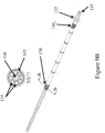
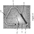
- Figure 13 illustrates, an exemplary arrangement and shape of the umbilical assembly 120 .
- the conduit 130 has opposite proximal and distal ends 130 1 , 130 2 .
- the proximal end 130 1 of the conduit 130 and the tubes 135 contained therein extend through the access aperture 40 (see Figures 15 and 16 , for example).
- the distal end 130 2 of the conduit 130 extends through the drum 150 and may connect to the rotor 45 to thereby allow the tubes 135 to be fluidly connected with the chambers 50 .
- the conduit distal end 130 2 includes a coupling 133 .
- the coupling 133 can couple the conduit 130 to the rotor 45 and therefore allow the tubes 135 to be fluidly connected with the chambers 50 .
- the coupling 133 has a hexagonal shape, although other shapes are contemplated, including other polygonal shapes.
- the coaxial half-speed rotation of the umbilical assembly 120 inhibits the tubes 135 of the umbilical assembly 120 from being completely twisted during rotation of the rotor 45 .
- the complete scientific explanation for this phenomenon can be found in, for example, U.S. Patent No. 3,586,413 to Adams. To summarize, if the rotor 45 has completed a first 360° rotation and the umbilical assembly 120 a 180° half-rotation in the same direction, the tubes 135 of the umbilical assembly 120 will be subjected to a 180° twist in one direction.
- the tubes 135 of the umbilical assembly 120 may be subjected to a continuous partial twist or flexure or bending during operation but are never completely rotated or twisted about their own axis.
- the umbilical assembly 120 of the present invention provides a transition from the "rotating world,” including the rotor 45 , to the "stationary world,” such as that area outside the enclosure 15 .
- Rotary unions and seals are not required, providing a sterile and completely closed system.
- Other advantages can include the use of disposable components that can be easily replaced, resulting in sterile paths, as described in more detail below.
- Umbilical-like arrangements for use with continuous flow centrifuges have been disclosed in, for example, U.S. Patent Nos. 4,216,770 , 4,419,089 , 4,389,206 , and 5,665,048 .
- these solutions do not adequately address the high stresses and strains imparted on the tubes due to the g-forces created by rotating the centrifuge at high speeds and/or due to the continuous fluid flow necessary to substantially immobilize particles.
- rotating the centrifuge at high speeds creates increased torque of the umbilical system and the tubes contained therein, and the arrangements disclosed to date do not allow the umbilical system and the tubes contained therein to be rotated at a high rate of speed for an acceptable amount of time before failing.
- the present invention addresses these deficiencies by providing a more robust umbilical assembly that can withstand higher rotational speeds (and therefore higher g-forces), allowing a system, such as a continuous flow centrifuge, to be "scaled up" to larger sizes without subjecting the umbilical assembly to immediate or rapid catastrophic failure. This is due to the configuration of the umbilical assemblies of the present invention, such as the umbilical assembly 120 illustrated in Figures 8-14 .
- the potting material 145 can maintain the tubes 135 in place, and thereby prevent the tubes 135 from excessive twisting relative to the conduit 130 .
- the potting material 145 can "lock" the tubes 135 and/or the conduit 130 together, thereby inhibiting movement of the tubes 135 relative to one another and/or relative to the conduit 130 .
- the potting material 145 can also provide a buffer between the individual tubes 135 , thereby preventing the tubes 135 from rubbing against one another.
- the potting material 145 can provide a buffer between the tubes 135 and the conduit 130 , thereby preventing the tubes 135 from rubbing against the conduit 130 during operation. Rubbing of these components can not only cause continual stress, but can also generate heat, further weakening the components.
- the flexible member 140 can serve to maintain the tubes 135 in an organized array around the flexible member 140 , further reducing twisting of the tubes 135 .
- the potting material 145 can serve to "lock" the conduit 130 , the tubes 135 , and/or the flexible member 140 together, thereby inhibiting movement of the components relative to one another.
- the potting material 145 may serve as a buffer between the tubes 135 and the flexible member 140 , thereby preventing the tubes 135 from rubbing against the flexible member during operation. Rubbing of these components can not only cause continual stress, but can also generate heat, further weakening the components.
- an appropriate material for the conduit 130 can prevent failure thereof due to rubbing against the umbilical guide 125 during operation.
- grease or other lubricous material can be applied between the conduit 130 and the guide 125 to further reduce friction and potential failure of the conduit 130 and/or the tubes 135 during operation (e.g., fatigue failure of the conduit 130 ).
- the inside of the guide 125 can be polished (e.g., mechanically polished) to further reduce friction between the conduit 130 and the guide 135 .
- the inside of the guide 125 and/or the outside of the conduit 130 can be coated with a lubricous material, such as Teflon®, to reduce friction between the two components.
- a system such as a continuous flow centrifuge without use of rotary seals or the like, has been successfully "scaled-up" as follows.
- the rotor and the chamber(s) can be rotated at speeds of at least 3000 RPM. This corresponds to a g-force of about 1000g at the chamber ( e.g. , at 1/3 the height of the chamber “cone” or 1/3 chamber height from the "tip" of the chamber).
- the fluid flow rates through each chamber can be at least 1 liter/minute.
- the total flow rate can be at least 4 liters/minute.
- the volume of each chamber can be at least 1 liter.
- the total chamber volume can be at least 4 liters.
- lower rotational speeds, flow rates, and/or chamber volumes can be employed for various operations (e.g ., the rotational speed of the rotor can range from 0-3000 RPM and/or the fluid flow rate through each chamber can range from 0-1 liters/minute and/or the volume of each chamber can be less than 1 liter).
- the aforementioned embodiments and the alternative embodiments disclosed below can allow for a robust system that is "scaled-up" to an even higher degree (e.g ., rotational speeds higher than 3000 RPM, flow rates higher than 1 liter/minute per chamber, chamber volumes greater than 1 liter, etc.).
- the aforementioned embodiments and the alternative embodiments disclosed below can allow for a robust system that employs rotation speeds of about 10, 25, 50, 100, 250, 500, 750, 1000, 1250, 1500, 1750, 2000, 2500, 3000, 5000, or 10,000 RPM or more or any subrange therein; it is also believed that the aforementioned embodiments and the alternative embodiments disclosed below can allow for a robust system that can produce and withstand g-forces of about 10, 25, 50, 100, 250, 500, 750, 1000, 1250, 1500, 1750, 2000, 2500, 3000, 5000, or 10,000g or more or any subrange therein.
- the aforementioned embodiments and the alternative embodiments disclosed below can allow for fluid flow rates of about 0.0001, 0.001, 0.01, 0.1, 0.25, 0.5, 0.75, 1, 1.25, 1.5, 1.75, 2, 2.5, 3, 5, 10, 20, 25, or 50 liters/minute per chamber or more or any subrange therein; it is also believed that the aforementioned embodiments and the alternative embodiments disclosed below can allow for individual chamber volumes of about 0.0001, 0.001, 0.01, 0.1, 0.25, 0.5, 0.75, 1, 1.25, 1.5, 1.75, 2, 2.5, 3, 5, 10, 20, 25, or 50 liters or more or any subrange therein.
- the flexible member along the centerline of the conduit can be omitted.
- One of the tubes may extend substantially along a centerline of the conduit, with the remaining tubes forming an array and surrounding the center tube.
- the center tube takes the place of the "dummy tube," and it connects with either the inlet or outlet path of one of the chambers. Potting material may be provided to prevent twisting and rubbing, as described in more detail above.
- the umbilical assembly could comprise one solid extrusion with a plurality of channels or passageways extending therethrough. Each channel or passageway would connect with either an inlet or an outlet of one of the chambers.
- the solid extrusion may be flexible, and may be contained within a guide to provide strength, such as the guide 120 described above.
- the solid extrusion assembly 330 may form part of the umbilical assembly 120 described herein. More specifically, the solid extrusion assembly 330 may take the place of the conduit 130 and the tubes 135 (as well as the potting material 145 and/or the flexible member 140 where these components are used) in all embodiments described above and below. Thus, it will be understood that the solid extrusion assembly 330 may fit within the guide tube 125 and define the conduit with spaced-apart elongate passageways therein.
- the solid extrusion assembly 330 includes a solid extrusion 330e .
- the solid extrusion is flexible with an outer wall and internal elongate channels or passageways 335 that define the spaced-apart passageways. Similar to the tubes 135 described in detail herein, the passageways 335 are in fluid communication with the chamber(s) 50 . In particular, one passageway 335 is in fluid communication with the inlet 55 of a respective chamber 50 and another, different passageway 335 is in fluid communication with the outlet 60 of the respective chamber 50 .
- the solid extrusion 330e includes eight passageways 335 , and is therefore configured for use with four chambers 50 . The extrusion 330e may include greater or fewer than eight passageways 335 as needed.
- the extrusion assembly 330 may take the place of at least the conduit 130 in the umbilical assembly 120 . Any differences between the extrusion assembly 330 and the conduit 130 will now be described.
- the passageways 335 generally take the place of the flexible tubes 135 .
- the passageways 335 may not extend all the way to the chamber(s) 50 and/or all the way to connection points outside the enclosure 15 (see Figures 15 and 16 ).
- connectors such as barbed connectors
- Connectors at a distal end of the passageways 335 may allow for tubing (which may be similar to the flexible tubing 135 described herein) to connect the passageways 335 with the inlet 55 and outlet 60 of the chamber(s) 50 (or the flange inlet and outlet paths 65, 70 , where used).
- connectors at a proximal end of the passageways 335 may allow for tubing (which may be similar to the flexible tubing 135 described herein) to connect the passageways 335 with components outside the enclosure 15, such as pumps or other tubing, which are described in more detail below.
- the solid extrusion assembly 330 includes a sheath 330s.
- the sheath 330s material and configuration may have similar properties and provide similar advantages to the conduit 130 material and configuration described above.
- the sheath 330s may help withstand friction with the guide tube 125 and/or may help transfer torque during operation.
- the sheath 330s may include ridges to minimize contact area with the guide tube 125 and/or to minimize friction during operation.
- the sheath 330s may be adhered to or may snugly fit around an outer wall of the solid extrusion 330e.
- the sheath 330s and the solid extrusion 330e are sized and configured such that there is an interference fit (perhaps a substantial interference fit) between the two components.
- the sheath 330s and the solid extrusion 330e may act as a single unit during operation ( i.e., as the extrusion assembly 330 ).
- the sheath 330s and the solid extrusion 330e may be integrated, and in some embodiments the sheath 330s may be omitted.
- the solid extrusion assembly 330 may provide the same or substantially the same advantages as the conduit 130, tubes 135, and potting material 145 as described in detail above.
- the passageways 335 may be positioned in the solid extrusion 330e such that they are spaced-apart from one another and/or from an outer wall of the extrusion 330e and/or from the sheath 330s, where used.
- the spaced-apart relationship may be maintained during operation, and therefore may help minimize movement/twisting of the passageways 335 relative to one another and/or may help minimize movement/twisting of the passageways 335 relative to the sheath 330s, where used.
- the result is a more robust umbilical assembly that can be used in "scaled-up" operations, as described in more detail above.
- the solid extrusion 330e may comprise polymeric material, such as PVC, platinum-cured silicon, C-Flex, and other similar materials.
- the sheath 330s, where used, may comprise materials similar to those described above with regard to the conduit 130.
- the umbilical assembly 120 including the conduit 130 and the tubes 135 (and optionally the potting material 145 and/or the flexible member 140 ).
- the umbilical assembly 120 may include the extrusion assembly 330 or simply the extrusion 330e in place of the conduit 130 , the tubes 135 , and/or the potting material 145 .
- a funnel 180 is provided on the rear side of the flange 35 and/or the door 20 .
- the funnel 180 includes an opening 185 opposite the aperture 40 .
- the funnel 180 is configured to accept at least part of the umbilical assembly 120 .
- the funnel 180 accepts the conduit 130 , with the tubes 135 contained therein.
- the conduit 130 passes through the opening 185 and the aperture 40 such that at least the tubes 135 extend through the aperture 30 .
- the tubes 135 can then be connected to additional components, as described in more detail below.
- the funnel 180 can provide for reduced strain/stress on the conduit 130 and the tubes 135 where the conduit makes a final bend before extending through the aperture 30 .
- the funnel 180 provides a controlled bend of the conduit 130 and tubes 135 contained therein. This can reduce the chance of failure of the conduit 130 and/or the tubes 135 at what otherwise would be a high stress concentration point.
- the centerline of the opening 185 is preferably aligned or substantially aligned with the axis of rotation of the umbilical assembly 120 ; otherwise, additional, unnecessary loads could be applied to the conduit 130 and/or the tubes 135 .
- the funnel 180 preferably has a bend radius that is greater than the minimum dynamic bend radius of the conduit 130 .
- the shape of the funnel 180 provides for a consistent bend of the conduit 130 and the tubes 135 contained therein while the umbilical assembly 120 is rotating during operation.
- the funnel 180 may be machined and/or polished to reduce friction or rubbing while the conduit 130 is rotating within the funnel 180 .
- grease or other lubricous material may be applied to the funnel 180 to further reduce friction or rubbing.
- the funnel and/or the outer surface of the conduit 130 may be coated with a lubricous material such as Teflon® to reduce friction or rubbing.
- At least one pump 200 may be provided on the enclosure 15 or on a panel thereon, or may be provided away from the enclosure 15 .
- At least one valve may be provided on the enclosure 15 or on a panel thereon, or may be integrated with the tubing shown on the right side of the enclosure 15 , or may be provided away from the enclosure 15 .
- one or more pinch valves may be provided on the enclosure 15 , with the pinch valves configured to allow tubing to be inserted therethrough such that the tubing can be squeezed (or pinched) closed or partially closed.
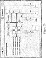
- Figure 17 illustrates an exemplary flow diagram of the system.
- the system may include two sets: the chambers/umbilical set and the valve/fluid path set.
- the chambers/umbilical set may include at least the chamber(s) 50 , the conduit 130 , and the tubes 135 within the conduit 130 .
- the tubes 135 in fluid communication with the inlet paths 65 of the chambers 50 may connect with the pump 200 (see also Figures 15 and 16 ).
- the tubes 135 in fluid communication with the outlet paths 70 of the chambers 50 may connect with at least one return tube 205 (see Figures 15 and 16 ).
- tubes 210 may connect with a harness or manifold 215 , which connects the chambers/umbilical set with the valve/fluid path set.
- the two disposable sets can be connected by a sterile tube welding process.
- the disposable sets can be supplied sealed and/or sterilized.
- the disposable sets can be connected without using any sort of connector (e.g ., harness, manifold, etc.), and the disposable sets do not need to be "opened," which could result in a loss of sterility.
- the valve/fluid path set typically comprises tubing and/or valves, which may be integrated with the tubing.
- the valve/fluid path set is configured to be routed through one or more valves, such as pinch valves included on the enclosure, for example.
- the valve/fluid path set includes the tubing seen on the right side of the enclosure 15 .
- the valve/fluid path set includes the return tube(s) 205 . It is noted that, although the tubes are shown as "broken" in Figures 15 and 16 , the tubes 135 protruding from the aperture 40 of the flange 35 will typically connect with the pump 200 and/or the return tube(s) 205 .
- the return tube(s) 205 and/or the tubes 135 running to the pump 200 may be routed through the handle 30 of the door 20 and/or kept in place by one or more holders 220 , such as hooks.
- the valve/fluid path set can connect to various containers, such as a bioreactor 230 , a waste media container 235 , a clean media container 240 , and/or a cell harvest container 245 .
- the various containers will typically be located away from the enclosure 15 , although at least some of the containers may be contained within the enclosure 15 in some embodiments.
- the lower (open) portions of the tubes on the right side of the enclosure 15 may connect with various containers, such as the containers described above.
- the valve/fluid path set may be configurable to perform various operations, as will be summarized in more detail below. At least one secondary pump 250 may be included on the enclosure 15 or away from the enclosure 15 ; the secondary pump 250 may be useful in at least some of these various operations.
- the chambers 50 , the conduit 130 , and/or the tubes 135 contained therein may be disposable.
- the disposable chambers 50 may be constructed of a flexible or resilient polymer, such as a transparent or translucent polymer, thereby forming a "bag chamber.”
- the disposable chambers 50 may be thermoformed.
- the material of the disposable chambers 50 may be relatively thin ( e.g ., less than 1 mm thick medical grade PVC).
- the material of the disposable chambers 50 may be another material (e.g ., FEP, C-Flex, blow molded EVA, low-density polyethylene, etc.), to permit compliance with good manufacturing practice (cGMP).
- the disposable chambers 50 may include inlet and outlet fluid paths 65, 70 (which may be integrated), as illustrated in Figure 5A , and as described in more detail above.
- the chamber holders 75 can inhibit failure of the disposable chambers 50 by accommodating the majority of or all of the loads experienced due to rotation of the rotor 45 and the chambers 50 .
- a system comprising two separate disposable fluid paths is also contemplated.
- the two sets described above i . e., the chambers/umbilical set and the valve/fluid path set
- the two sets described above may be separately disposable.
- the chambers 50 , the conduit 130 , and the tubes 135 contained therein may comprise a first disposable flow path (Set #1).
- the tubing and/or valves to the right of the harness or manifold 215 may comprise a second disposable flow path (Set #2).
- the return tube(s) 205 will typically be included in disposable Set #2, but may be included in either disposable flow path.
- the disposable fluid path(s) can provide advantages over conventional continuous flow centrifuges and like apparatus.
- Systems that do not employ disposable flow paths generally have to adhere to Cleaning-in-Place (CIP) and Sterilization-in-Place (SIP) procedures and standards. This is especially the case for those systems that perform operations that are sensitive to contamination, such as cell culturing/harvesting and blood processing, for example.
- CIP Cleaning-in-Place
- SIP Sterilization-in-Place
- the disposable flow paths described herein can eliminate the need to perform CIP and SIP procedures.
- the use of completely disposable fluid paths permits compliance with good manufacturing practice (cGMP).
- the paths can be provided as sterile components ready for insertion and use.
- media containing particles such as cells will be fed in the rotating chambers 50 to form a fluidized bed of cells. After the chambers 50 are filled with cells, the flow will be reversed to empty out the chambers 50 .
- the system i.e ., the rotors and the chambers
- the cycle can be repeated to concentrate cells from large volumes.
- particles such as cells are immobilized in the rotating chambers 50 in fluidized beds for culturing and/or harvesting.
- cells and media may be removed from the bioreactor 230 and transported to the chambers 50 .
- a continuous flow of media and cells substantially opposes the centrifugal force created by the rotating chambers 50 , thereby immobilizing the cells in a fluidized bed.
- the cells are provided with fresh media continuously and spent media is removed, such as to the waste container 235 .
- the cells can then be removed from the chambers 50 , perhaps by reversing the fluid flow and returning the cells to the bioreactor 230 or the cell harvest container 245 .
- the systems disclosed herein can also perform media exchanges during cell culture or harvest.
- cell culture is first fed to the rotating chambers 50 to form a bed of fluidized cells, and then a new media or buffer is fed through the inlet paths 65 of the chambers 50 to be perfused through the bed.
- the new media or buffer may be introduced from the clean media container 240 .
- the chambers 50 are emptied out by reversing the flow ( i . e ., introducing media to the outlet paths 70 of the chambers 50 ).
- the media/ buffer exchange application could be used prior to additional processes such as transfection, cell dispensing, seeding a bioreactor, etc.
- the systems are also capable of separating population of cells based on density and/or size.
- fluid containing different populations of cells will be fed into the rotating chambers 50 .
- Cells will be separated by modulating the fluid feed rate and/or the centrifugal force (i.e ., the rotational speed of the rotor).
- the centrifugal force i.e ., the rotational speed of the rotor.
- lighter/smaller cells will exit out of the chambers 50 with media.
- fresh media or buffer could be used to separate another population by once again adjusting the feed rate and/or centrifugal force. This process can be repeated several times to separate multiple populations of cells that differ by density and/or size.
- heavier/larger cells are harvested by reversing the flow of fresh media.
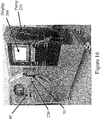
- a display 260 may be provided on the enclosure 15, or may be provided on a panel attached or adjacent to the enclosure 15, or may be provided away from the enclosure 15.
- the display 260 is connected ( e.g. , directly or wirelessly) to at least one controller (not shown).
- controllers associated with the various components of the system, including the motor, the pump(s), the valves, etc.
- the display 260 may allow parameters to be entered and data or progress to be read by an operator.
- the display may include touch screen buttons that dictate the operation of various components, as seen in Figure 18 .
- there is a separate user input device such as a keyboard; in other words, the display may not employ a touch screen.
- a light source and/or a camera may be included on the enclosure or in the interior cavity of the enclosure.
- the light source and/or the camera may be useful to illuminate the chamber(s) and/or capture images of the chamber(s) ( e.g ., the interior of the chamber(s) during operation).
- the captured images may be useful to provide feedback to the operator and/or the system as to the progress of the particular process taking place within the chamber(s).
- the camera may be in communication with the display (either directly or via a controller), such that the images may be transmitted to the display, for example.
- the controller(s) and/or software associated with the controller(s) may automatically correlate captured images with a particular chamber.
Landscapes
- Health & Medical Sciences (AREA)
- Life Sciences & Earth Sciences (AREA)
- Organic Chemistry (AREA)
- Engineering & Computer Science (AREA)
- Bioinformatics & Cheminformatics (AREA)
- Chemical & Material Sciences (AREA)
- Zoology (AREA)
- Wood Science & Technology (AREA)
- Sustainable Development (AREA)
- Microbiology (AREA)
- Biotechnology (AREA)
- Biomedical Technology (AREA)
- Biochemistry (AREA)
- General Engineering & Computer Science (AREA)
- General Health & Medical Sciences (AREA)
- Genetics & Genomics (AREA)
- Molecular Biology (AREA)
- Centrifugal Separators (AREA)
- Crushing And Pulverization Processes (AREA)
Priority Applications (1)
| Application Number | Priority Date | Filing Date | Title |
|---|---|---|---|
| EP18153768.9A EP3391970B1 (en) | 2009-10-06 | 2010-10-06 | Method and apparatus for manipulating particles |
Applications Claiming Priority (2)
| Application Number | Priority Date | Filing Date | Title |
|---|---|---|---|
| US24905809P | 2009-10-06 | 2009-10-06 | |
| PCT/US2010/051631 WO2011044237A1 (en) | 2009-10-06 | 2010-10-06 | Methods, systems and apparatus for manipulating particles |
Related Child Applications (2)
| Application Number | Title | Priority Date | Filing Date |
|---|---|---|---|
| EP18153768.9A Division-Into EP3391970B1 (en) | 2009-10-06 | 2010-10-06 | Method and apparatus for manipulating particles |
| EP18153768.9A Division EP3391970B1 (en) | 2009-10-06 | 2010-10-06 | Method and apparatus for manipulating particles |
Publications (2)
| Publication Number | Publication Date |
|---|---|
| EP2485846A1 EP2485846A1 (en) | 2012-08-15 |
| EP2485846B1 true EP2485846B1 (en) | 2019-07-17 |
Family
ID=43532970
Family Applications (2)
| Application Number | Title | Priority Date | Filing Date |
|---|---|---|---|
| EP10771586.4A Active EP2485846B1 (en) | 2009-10-06 | 2010-10-06 | Methods, systems and apparatus for manipulating particles |
| EP18153768.9A Active EP3391970B1 (en) | 2009-10-06 | 2010-10-06 | Method and apparatus for manipulating particles |
Family Applications After (1)
| Application Number | Title | Priority Date | Filing Date |
|---|---|---|---|
| EP18153768.9A Active EP3391970B1 (en) | 2009-10-06 | 2010-10-06 | Method and apparatus for manipulating particles |
Country Status (8)
| Country | Link |
|---|---|
| US (2) | US9839920B2 (ja) |
| EP (2) | EP2485846B1 (ja) |
| JP (3) | JP5774012B2 (ja) |
| KR (2) | KR20120102050A (ja) |
| AU (1) | AU2010303553B2 (ja) |
| CA (1) | CA2776750C (ja) |
| SG (1) | SG10201406807QA (ja) |
| WO (1) | WO2011044237A1 (ja) |
Cited By (6)
| Publication number | Priority date | Publication date | Assignee | Title |
|---|---|---|---|---|
| EP3936600A1 (en) | 2020-07-06 | 2022-01-12 | Sartorius Stedim Biotech GmbH | Automated centrifuge setup of a bioprocessing installation |
| EP3936601A1 (en) | 2020-07-06 | 2022-01-12 | Sartorius Stedim Biotech GmbH | Clarification setup of a bioprocessing installation |
| EP4299188A1 (de) | 2022-06-30 | 2024-01-03 | Sigma Laborzentrifugen GmbH | Zentrifuge, verfahren zum betrieb einer zentrifuge und computerlesbares medium |
| EP4321254A1 (de) | 2022-08-09 | 2024-02-14 | Sigma Laborzentrifugen GmbH | Durchflusszentrifuge |
| EP4321253A1 (de) | 2022-08-09 | 2024-02-14 | Sigma Laborzentrifugen GmbH | Durchflusszentrifuge und ausgleichsrotor-führungseinrichtung |
| EP4321255A1 (de) | 2022-08-12 | 2024-02-14 | Sigma Laborzentrifugen GmbH | Durchflusszentrifuge und verfahren zur herbeiführung eines betriebsbereiten zustands einer durchflusszentrifuge |
Families Citing this family (12)
| Publication number | Priority date | Publication date | Assignee | Title |
|---|---|---|---|---|
| KR20120102050A (ko) * | 2009-10-06 | 2012-09-17 | 케이비아이 바이오파마, 인크. | 입자를 조작하는 방법, 시스템 및 장치 |
| US8257239B2 (en) * | 2010-06-15 | 2012-09-04 | Fenwal, Inc. | Umbilicus for use in an umbilicus-driven fluid processing |
| TWI637057B (zh) | 2012-11-09 | 2018-10-01 | 拜爾沙納有限公司 | 具交替生物反應器用途之不連續進料批次製程 |
| US9383044B2 (en) | 2013-02-15 | 2016-07-05 | Fenwal, Inc. | Low cost umbilicus without overmolding |
| US10099228B2 (en) * | 2015-10-09 | 2018-10-16 | Invetech, Inc. | Apparatus for performing counter flow centrifugation and method of using same |
| JP7248324B2 (ja) * | 2017-05-12 | 2023-03-29 | サイノジー プロダクツ プロプライエタリー リミテッド | コンパクトな逆流遠心分離システムおよびそれに用いる分離チャンバ |
| EP3743214A4 (en) * | 2018-01-22 | 2021-10-20 | Scinogy Products Pty Ltd | SYSTEM, METHOD AND CONTROL UNIT FOR RECOVERING CONCENTRATED PARTICLES SUSPENDED IN LIQUID |
| JP7349058B2 (ja) * | 2019-02-25 | 2023-09-22 | エイブル株式会社 | 培養液処理装置及び液体処理装置 |
| EP4056671A1 (en) | 2021-03-10 | 2022-09-14 | Sartorius Stedim Biotech GmbH | Method for operating a bioprocess installation |
| EP4124653A1 (en) | 2021-07-27 | 2023-02-01 | Sartorius Stedim Biotech GmbH | Method for producing a bioproduct |
| EP4209575A1 (en) * | 2022-01-11 | 2023-07-12 | Sartorius Stedim North America Inc. | Method for operating a clarification setup |
| EP4209576A1 (en) * | 2022-01-11 | 2023-07-12 | Sartorius Stedim North America Inc. | Method for operating a clarification setup |
Family Cites Families (48)
| Publication number | Priority date | Publication date | Assignee | Title |
|---|---|---|---|---|
| US3347454A (en) | 1964-05-13 | 1967-10-17 | Baxter Laboratories Inc | Method and apparatus for the centrifugal washing of particles in a closed system |
| US3586413A (en) | 1969-03-25 | 1971-06-22 | Dale A Adams | Apparatus for providing energy communication between a moving and a stationary terminal |
| US4056224A (en) * | 1975-03-27 | 1977-11-01 | Baxter Travenol Laboratories, Inc. | Flow system for centrifugal liquid processing apparatus |
| US4419089A (en) | 1977-07-19 | 1983-12-06 | The United States Of America As Represented By The Department Of Health And Human Services | Blood cell separator |
| US4114802A (en) | 1977-08-29 | 1978-09-19 | Baxter Travenol Laboratories, Inc. | Centrifugal apparatus with biaxial connector |
| US4146172A (en) * | 1977-10-18 | 1979-03-27 | Baxter Travenol Laboratories, Inc. | Centrifugal liquid processing system |
| JPS601513B2 (ja) * | 1977-12-14 | 1985-01-16 | 株式会社クボタ | フレキシブル複合管 |
| US4216770A (en) | 1979-02-09 | 1980-08-12 | Baxter Travenol Laboratories, Inc. | Sickle cell therapeutic treatment |
| JPS5665647A (en) | 1979-11-05 | 1981-06-03 | Asahi Chem Ind Co Ltd | Fluid passing device |
| US4350283A (en) * | 1980-07-01 | 1982-09-21 | Beckman Instruments, Inc. | Centrifugal elutriator rotor |
| US4389206A (en) | 1980-10-09 | 1983-06-21 | Baxter Travenol Laboratories, Inc. | Centrifugal processing apparatus and rotatable processing bowl apparatus |
| US4372484A (en) * | 1981-02-04 | 1983-02-08 | Gambro Ab | Device for the separation of a liquid, especially whole blood |
| JPS583747A (ja) | 1981-06-29 | 1983-01-10 | Akira Washida | 鋳物用型 |
| JPS61284254A (ja) | 1985-06-12 | 1986-12-15 | 川澄化学工業株式会社 | プラズマフエレ−シスバツグ用のコネクタ− |
| JPS6314628A (ja) | 1986-07-08 | 1988-01-21 | 株式会社クボタ | 刈取収穫機の自動変速操作構造 |
| SE454414B (sv) * | 1986-09-12 | 1988-05-02 | Alfa Laval Separation Ab | Roterbar till- och avloppsledning vid centrifugalseparator |
| US5656163A (en) * | 1987-01-30 | 1997-08-12 | Baxter International Inc. | Chamber for use in a rotating field to separate blood components |
| US4939087A (en) | 1987-05-12 | 1990-07-03 | Washington State University Research Foundation, Inc. | Method for continuous centrifugal bioprocessing |
| JPH0699439B2 (ja) | 1988-02-03 | 1994-12-07 | 日産化学工業株式会社 | ピラノベンゾオキサジアゾール誘導体 |
| JPH0515813A (ja) * | 1991-07-09 | 1993-01-26 | Hitachi Koki Co Ltd | エルトリエータロータ装置の分離チヤンバの分離室 |
| AU652888B2 (en) | 1991-12-23 | 1994-09-08 | Baxter International Inc. | Centrifugal processing system with direct access drawer |
| WO1994008689A1 (en) | 1992-10-22 | 1994-04-28 | Baxter International Inc. | Blood processing systems with improved data transfer between stationary and rotating elements |
| US5409443A (en) * | 1993-04-15 | 1995-04-25 | Separation Technology, Inc. | Tube holder arrangement for blood centrifuge |
| US5622819A (en) | 1995-03-28 | 1997-04-22 | Kinetic Biosystems, Inc. | Centrifugal fermentation process |
| US6916652B2 (en) * | 1995-03-28 | 2005-07-12 | Kinetic Biosystems, Inc. | Biocatalyst chamber encapsulation system for bioremediation and fermentation |
| US6133019A (en) | 1995-03-28 | 2000-10-17 | Kinetic Biosystems, Inc. | Centrifugal fermentation process |
| US6660509B1 (en) | 1995-03-28 | 2003-12-09 | Kinetic Biosystems, Inc. | Methods and devices for remediation and fermentation |
| US6214617B1 (en) | 1995-03-28 | 2001-04-10 | Kinetic Biosystems, Inc. | Centrifugal fermentation process |
| US20050266548A1 (en) | 1995-03-28 | 2005-12-01 | Kbi Biopharma, Inc. | Biocatalyst chamber encapsulation system for bioremediation and fermentation with improved rotor |
| US5674173A (en) | 1995-04-18 | 1997-10-07 | Cobe Laboratories, Inc. | Apparatus for separating particles |
| US5939319A (en) | 1995-04-18 | 1999-08-17 | Cobe Laboratories, Inc. | Particle separation method and apparatus |
| US5665048A (en) | 1995-12-22 | 1997-09-09 | Jorgensen; Glen | Circumferentially driven continuous flow centrifuge |
| US6051146A (en) | 1998-01-20 | 2000-04-18 | Cobe Laboratories, Inc. | Methods for separation of particles |
| US6334842B1 (en) | 1999-03-16 | 2002-01-01 | Gambro, Inc. | Centrifugal separation apparatus and method for separating fluid components |
| WO2001018396A1 (en) | 1999-09-03 | 2001-03-15 | Baxter International Inc. | Programmable, fluid pressure actuated blood processing systems and methods |
| WO2001055296A1 (en) | 2000-01-31 | 2001-08-02 | Kinetic Biosystems, Inc. | Methods and devices for remediation and fermentation |
| US6354986B1 (en) | 2000-02-16 | 2002-03-12 | Gambro, Inc. | Reverse-flow chamber purging during centrifugal separation |
| EP1441823B1 (en) | 2001-11-09 | 2013-08-21 | KBI Biopharma, Inc. | Methods and compositions for chromatography |
| DE60230997D1 (de) | 2001-12-05 | 2009-03-12 | Caridianbct Inc | Verfahren und vorrichtung zur trennung von blutbestandteilen |
| US7479123B2 (en) * | 2002-03-04 | 2009-01-20 | Therakos, Inc. | Method for collecting a desired blood component and performing a photopheresis treatment |
| AU2004254632B2 (en) | 2003-07-02 | 2009-02-12 | Terumo Bct, Inc. | Monitoring and control system for blood processing |
| US7060018B2 (en) * | 2003-09-11 | 2006-06-13 | Cobe Cardiovascular, Inc. | Centrifuge apparatus for processing blood |
| US7476209B2 (en) | 2004-12-21 | 2009-01-13 | Therakos, Inc. | Method and apparatus for collecting a blood component and performing a photopheresis treatment |
| EP1674104A1 (en) | 2004-12-24 | 2006-06-28 | Institut National De La Sante Et De La Recherche Medicale (Inserm) | Uridine derivatives as antiviral drugs against a flaviviridae, especially HCV |
| JP2010532223A (ja) | 2007-06-29 | 2010-10-07 | アマグ ファーマシューティカルズ, インコーポレイテッド | マクロファージ増強mri(memri) |
| DE102007054339B4 (de) * | 2007-11-14 | 2009-10-29 | Miltenyi Biotec Gmbh | Vorrichtung zum Übertragen von Energie und/ oder eines Stoffes auf eine rotierende Einrichtung, sowie deren Verwendung |
| JP5746025B2 (ja) | 2008-07-16 | 2015-07-08 | ケーセップ・システムズ,リミテッド・ライアビリティ・カンパニー | 流動床を使用して粒子を操作するための方法及びシステム |
| KR20120102050A (ko) * | 2009-10-06 | 2012-09-17 | 케이비아이 바이오파마, 인크. | 입자를 조작하는 방법, 시스템 및 장치 |
-
2010
- 2010-10-06 KR KR1020127011664A patent/KR20120102050A/ko active Search and Examination
- 2010-10-06 JP JP2012533278A patent/JP5774012B2/ja active Active
- 2010-10-06 WO PCT/US2010/051631 patent/WO2011044237A1/en active Application Filing
- 2010-10-06 AU AU2010303553A patent/AU2010303553B2/en active Active
- 2010-10-06 US US13/499,807 patent/US9839920B2/en active Active
- 2010-10-06 EP EP10771586.4A patent/EP2485846B1/en active Active
- 2010-10-06 CA CA2776750A patent/CA2776750C/en active Active
- 2010-10-06 KR KR1020177036985A patent/KR101940440B1/ko active IP Right Grant
- 2010-10-06 EP EP18153768.9A patent/EP3391970B1/en active Active
- 2010-10-06 SG SG10201406807QA patent/SG10201406807QA/en unknown
-
2015
- 2015-06-29 JP JP2015129685A patent/JP6468959B2/ja active Active
-
2017
- 2017-11-08 US US15/806,670 patent/US10888878B2/en active Active
-
2018
- 2018-10-29 JP JP2018202700A patent/JP6679695B2/ja active Active
Non-Patent Citations (1)
| Title |
|---|
| None * |
Cited By (12)
| Publication number | Priority date | Publication date | Assignee | Title |
|---|---|---|---|---|
| EP3936600A1 (en) | 2020-07-06 | 2022-01-12 | Sartorius Stedim Biotech GmbH | Automated centrifuge setup of a bioprocessing installation |
| EP3936601A1 (en) | 2020-07-06 | 2022-01-12 | Sartorius Stedim Biotech GmbH | Clarification setup of a bioprocessing installation |
| WO2022008543A1 (en) | 2020-07-06 | 2022-01-13 | Sartorius Stedim Biotech Gmbh | Automated centrifuge setup of a bioprocessing installation |
| WO2022008536A1 (en) | 2020-07-06 | 2022-01-13 | Sartorius Stedim Biotech Gmbh | Clarification setup of a bioprocessing installation |
| EP4299188A1 (de) | 2022-06-30 | 2024-01-03 | Sigma Laborzentrifugen GmbH | Zentrifuge, verfahren zum betrieb einer zentrifuge und computerlesbares medium |
| WO2024002794A1 (de) | 2022-06-30 | 2024-01-04 | Sigma Laborzentrifugen Gmbh | Zentrifuge, verfahren zum betrieb einer zentrifuge und computerlesbares medium |
| EP4321254A1 (de) | 2022-08-09 | 2024-02-14 | Sigma Laborzentrifugen GmbH | Durchflusszentrifuge |
| EP4321253A1 (de) | 2022-08-09 | 2024-02-14 | Sigma Laborzentrifugen GmbH | Durchflusszentrifuge und ausgleichsrotor-führungseinrichtung |
| WO2024033255A1 (de) | 2022-08-09 | 2024-02-15 | Sartorius Stedim North America Inc. | Durchflusszentrifuge und ausgleichsrotor-führungseinrichtung |
| WO2024033257A1 (de) | 2022-08-09 | 2024-02-15 | Sartorius Stedim North America Inc., | Durchflusszentrifuge |
| EP4321255A1 (de) | 2022-08-12 | 2024-02-14 | Sigma Laborzentrifugen GmbH | Durchflusszentrifuge und verfahren zur herbeiführung eines betriebsbereiten zustands einer durchflusszentrifuge |
| WO2024033371A1 (de) | 2022-08-12 | 2024-02-15 | Sartorius Stedim Biotech Gmbh | Durchflusszentrifuge und verfahren zur herbeiführung eines betriebsbereiten zustands einer durchflusszentrifuge |
Also Published As
| Publication number | Publication date |
|---|---|
| US9839920B2 (en) | 2017-12-12 |
| US20120270717A1 (en) | 2012-10-25 |
| KR101940440B1 (ko) | 2019-01-18 |
| US20180065127A1 (en) | 2018-03-08 |
| AU2010303553A1 (en) | 2012-05-03 |
| EP3391970A1 (en) | 2018-10-24 |
| JP6468959B2 (ja) | 2019-02-13 |
| SG10201406807QA (en) | 2015-01-29 |
| JP2019030876A (ja) | 2019-02-28 |
| US10888878B2 (en) | 2021-01-12 |
| JP5774012B2 (ja) | 2015-09-02 |
| EP2485846A1 (en) | 2012-08-15 |
| JP6679695B2 (ja) | 2020-04-15 |
| CA2776750C (en) | 2018-05-15 |
| JP2015211968A (ja) | 2015-11-26 |
| JP2013506556A (ja) | 2013-02-28 |
| AU2010303553B2 (en) | 2014-07-24 |
| CA2776750A1 (en) | 2011-04-14 |
| KR20180002895A (ko) | 2018-01-08 |
| KR20120102050A (ko) | 2012-09-17 |
| WO2011044237A1 (en) | 2011-04-14 |
| EP3391970B1 (en) | 2020-01-22 |
Similar Documents
| Publication | Publication Date | Title |
|---|---|---|
| US10888878B2 (en) | Methods, systems and apparatus for manipulating particles | |
| JP7248324B2 (ja) | コンパクトな逆流遠心分離システムおよびそれに用いる分離チャンバ | |
| US8808978B2 (en) | System and method for automated platelet wash | |
| JP2002533171A (ja) | 造血幹細胞の濃縮に特化した血液分離装置 | |
| WO2016158793A1 (ja) | 細胞分離デバイス及び細胞分離システム | |
| AU2014250662B2 (en) | Methods, systems and apparatus for manipulating particles | |
| US8727958B2 (en) | Apparatus and method for transferring energy and/or a substance to rotating means | |
| JP5876047B2 (ja) | 血液及び血液成分を処理するための遠心分離器 | |
| CN111417415B (zh) | 生物处理系统 | |
| JP2002503152A (ja) | 可撓性の流体処理容器の保持のためのキャリヤ | |
| CN211255955U (zh) | 一种用于细胞培养的在线连续离心装置 | |
| EP2767343B1 (en) | Low cost umbilicus without overmolding | |
| JP2023530246A (ja) | バッチバイオプロセシングの遠心分離機ロータ | |
| KR101263821B1 (ko) | 멀티웨이 밸브 및 이를 이용한 재생성 세포 추출시스템 |
Legal Events
| Date | Code | Title | Description |
|---|---|---|---|
| PUAI | Public reference made under article 153(3) epc to a published international application that has entered the european phase |
Free format text: ORIGINAL CODE: 0009012 |
|
| 17P | Request for examination filed |
Effective date: 20120419 |
|
| AK | Designated contracting states |
Kind code of ref document: A1 Designated state(s): AL AT BE BG CH CY CZ DE DK EE ES FI FR GB GR HR HU IE IS IT LI LT LU LV MC MK MT NL NO PL PT RO RS SE SI SK SM TR |
|
| RIN1 | Information on inventor provided before grant (corrected) |
Inventor name: MEHTA, SUNIL Inventor name: HERMAN, TOD Inventor name: WILSON, STEPHEN Inventor name: MCMAHON, JOE Inventor name: FITZPATRICK, IAN Inventor name: CRAIG, TIMOTHY |
|
| DAX | Request for extension of the european patent (deleted) | ||
| REG | Reference to a national code |
Ref country code: HK Ref legal event code: DE Ref document number: 1170979 Country of ref document: HK |
|
| RAP1 | Party data changed (applicant data changed or rights of an application transferred) |
Owner name: KSEP SYSTEMS, LLC |
|
| RAP1 | Party data changed (applicant data changed or rights of an application transferred) |
Owner name: SARTORIUS STEDIM NORTH AMERICA INC. |
|
| STAA | Information on the status of an ep patent application or granted ep patent |
Free format text: STATUS: EXAMINATION IS IN PROGRESS |
|
| 17Q | First examination report despatched |
Effective date: 20170720 |
|
| GRAP | Despatch of communication of intention to grant a patent |
Free format text: ORIGINAL CODE: EPIDOSNIGR1 |
|
| STAA | Information on the status of an ep patent application or granted ep patent |
Free format text: STATUS: GRANT OF PATENT IS INTENDED |
|
| INTG | Intention to grant announced |
Effective date: 20190320 |
|
| GRAS | Grant fee paid |
Free format text: ORIGINAL CODE: EPIDOSNIGR3 |
|
| GRAA | (expected) grant |
Free format text: ORIGINAL CODE: 0009210 |
|
| STAA | Information on the status of an ep patent application or granted ep patent |
Free format text: STATUS: THE PATENT HAS BEEN GRANTED |
|
| AK | Designated contracting states |
Kind code of ref document: B1 Designated state(s): AL AT BE BG CH CY CZ DE DK EE ES FI FR GB GR HR HU IE IS IT LI LT LU LV MC MK MT NL NO PL PT RO RS SE SI SK SM TR |
|
| REG | Reference to a national code |
Ref country code: GB Ref legal event code: FG4D |
|
| REG | Reference to a national code |
Ref country code: CH Ref legal event code: EP |
|
| REG | Reference to a national code |
Ref country code: IE Ref legal event code: FG4D |
|
| REG | Reference to a national code |
Ref country code: DE Ref legal event code: R096 Ref document number: 602010060052 Country of ref document: DE |
|
| REG | Reference to a national code |
Ref country code: AT Ref legal event code: REF Ref document number: 1155356 Country of ref document: AT Kind code of ref document: T Effective date: 20190815 |
|
| REG | Reference to a national code |
Ref country code: CH Ref legal event code: NV Representative=s name: VALIPAT S.A. C/O BOVARD SA NEUCHATEL, CH |
|
| REG | Reference to a national code |
Ref country code: NL Ref legal event code: MP Effective date: 20190717 |
|
| REG | Reference to a national code |
Ref country code: LT Ref legal event code: MG4D |
|
| REG | Reference to a national code |
Ref country code: AT Ref legal event code: MK05 Ref document number: 1155356 Country of ref document: AT Kind code of ref document: T Effective date: 20190717 |
|
| PG25 | Lapsed in a contracting state [announced via postgrant information from national office to epo] |
Ref country code: LT Free format text: LAPSE BECAUSE OF FAILURE TO SUBMIT A TRANSLATION OF THE DESCRIPTION OR TO PAY THE FEE WITHIN THE PRESCRIBED TIME-LIMIT Effective date: 20190717 Ref country code: PT Free format text: LAPSE BECAUSE OF FAILURE TO SUBMIT A TRANSLATION OF THE DESCRIPTION OR TO PAY THE FEE WITHIN THE PRESCRIBED TIME-LIMIT Effective date: 20191118 Ref country code: FI Free format text: LAPSE BECAUSE OF FAILURE TO SUBMIT A TRANSLATION OF THE DESCRIPTION OR TO PAY THE FEE WITHIN THE PRESCRIBED TIME-LIMIT Effective date: 20190717 Ref country code: AT Free format text: LAPSE BECAUSE OF FAILURE TO SUBMIT A TRANSLATION OF THE DESCRIPTION OR TO PAY THE FEE WITHIN THE PRESCRIBED TIME-LIMIT Effective date: 20190717 Ref country code: NL Free format text: LAPSE BECAUSE OF FAILURE TO SUBMIT A TRANSLATION OF THE DESCRIPTION OR TO PAY THE FEE WITHIN THE PRESCRIBED TIME-LIMIT Effective date: 20190717 Ref country code: BG Free format text: LAPSE BECAUSE OF FAILURE TO SUBMIT A TRANSLATION OF THE DESCRIPTION OR TO PAY THE FEE WITHIN THE PRESCRIBED TIME-LIMIT Effective date: 20191017 Ref country code: NO Free format text: LAPSE BECAUSE OF FAILURE TO SUBMIT A TRANSLATION OF THE DESCRIPTION OR TO PAY THE FEE WITHIN THE PRESCRIBED TIME-LIMIT Effective date: 20191017 Ref country code: SE Free format text: LAPSE BECAUSE OF FAILURE TO SUBMIT A TRANSLATION OF THE DESCRIPTION OR TO PAY THE FEE WITHIN THE PRESCRIBED TIME-LIMIT Effective date: 20190717 Ref country code: HR Free format text: LAPSE BECAUSE OF FAILURE TO SUBMIT A TRANSLATION OF THE DESCRIPTION OR TO PAY THE FEE WITHIN THE PRESCRIBED TIME-LIMIT Effective date: 20190717 |
|
| PG25 | Lapsed in a contracting state [announced via postgrant information from national office to epo] |
Ref country code: LV Free format text: LAPSE BECAUSE OF FAILURE TO SUBMIT A TRANSLATION OF THE DESCRIPTION OR TO PAY THE FEE WITHIN THE PRESCRIBED TIME-LIMIT Effective date: 20190717 Ref country code: IS Free format text: LAPSE BECAUSE OF FAILURE TO SUBMIT A TRANSLATION OF THE DESCRIPTION OR TO PAY THE FEE WITHIN THE PRESCRIBED TIME-LIMIT Effective date: 20191117 Ref country code: RS Free format text: LAPSE BECAUSE OF FAILURE TO SUBMIT A TRANSLATION OF THE DESCRIPTION OR TO PAY THE FEE WITHIN THE PRESCRIBED TIME-LIMIT Effective date: 20190717 Ref country code: GR Free format text: LAPSE BECAUSE OF FAILURE TO SUBMIT A TRANSLATION OF THE DESCRIPTION OR TO PAY THE FEE WITHIN THE PRESCRIBED TIME-LIMIT Effective date: 20191018 Ref country code: AL Free format text: LAPSE BECAUSE OF FAILURE TO SUBMIT A TRANSLATION OF THE DESCRIPTION OR TO PAY THE FEE WITHIN THE PRESCRIBED TIME-LIMIT Effective date: 20190717 Ref country code: ES Free format text: LAPSE BECAUSE OF FAILURE TO SUBMIT A TRANSLATION OF THE DESCRIPTION OR TO PAY THE FEE WITHIN THE PRESCRIBED TIME-LIMIT Effective date: 20190717 |
|
| PG25 | Lapsed in a contracting state [announced via postgrant information from national office to epo] |
Ref country code: TR Free format text: LAPSE BECAUSE OF FAILURE TO SUBMIT A TRANSLATION OF THE DESCRIPTION OR TO PAY THE FEE WITHIN THE PRESCRIBED TIME-LIMIT Effective date: 20190717 |
|
| PG25 | Lapsed in a contracting state [announced via postgrant information from national office to epo] |
Ref country code: DK Free format text: LAPSE BECAUSE OF FAILURE TO SUBMIT A TRANSLATION OF THE DESCRIPTION OR TO PAY THE FEE WITHIN THE PRESCRIBED TIME-LIMIT Effective date: 20190717 Ref country code: EE Free format text: LAPSE BECAUSE OF FAILURE TO SUBMIT A TRANSLATION OF THE DESCRIPTION OR TO PAY THE FEE WITHIN THE PRESCRIBED TIME-LIMIT Effective date: 20190717 Ref country code: PL Free format text: LAPSE BECAUSE OF FAILURE TO SUBMIT A TRANSLATION OF THE DESCRIPTION OR TO PAY THE FEE WITHIN THE PRESCRIBED TIME-LIMIT Effective date: 20190717 Ref country code: IT Free format text: LAPSE BECAUSE OF FAILURE TO SUBMIT A TRANSLATION OF THE DESCRIPTION OR TO PAY THE FEE WITHIN THE PRESCRIBED TIME-LIMIT Effective date: 20190717 Ref country code: RO Free format text: LAPSE BECAUSE OF FAILURE TO SUBMIT A TRANSLATION OF THE DESCRIPTION OR TO PAY THE FEE WITHIN THE PRESCRIBED TIME-LIMIT Effective date: 20190717 |
|
| PG25 | Lapsed in a contracting state [announced via postgrant information from national office to epo] |
Ref country code: IS Free format text: LAPSE BECAUSE OF FAILURE TO SUBMIT A TRANSLATION OF THE DESCRIPTION OR TO PAY THE FEE WITHIN THE PRESCRIBED TIME-LIMIT Effective date: 20200224 Ref country code: SM Free format text: LAPSE BECAUSE OF FAILURE TO SUBMIT A TRANSLATION OF THE DESCRIPTION OR TO PAY THE FEE WITHIN THE PRESCRIBED TIME-LIMIT Effective date: 20190717 Ref country code: SK Free format text: LAPSE BECAUSE OF FAILURE TO SUBMIT A TRANSLATION OF THE DESCRIPTION OR TO PAY THE FEE WITHIN THE PRESCRIBED TIME-LIMIT Effective date: 20190717 Ref country code: CZ Free format text: LAPSE BECAUSE OF FAILURE TO SUBMIT A TRANSLATION OF THE DESCRIPTION OR TO PAY THE FEE WITHIN THE PRESCRIBED TIME-LIMIT Effective date: 20190717 Ref country code: MC Free format text: LAPSE BECAUSE OF FAILURE TO SUBMIT A TRANSLATION OF THE DESCRIPTION OR TO PAY THE FEE WITHIN THE PRESCRIBED TIME-LIMIT Effective date: 20190717 |
|
| REG | Reference to a national code |
Ref country code: DE Ref legal event code: R097 Ref document number: 602010060052 Country of ref document: DE |
|
| PLBE | No opposition filed within time limit |
Free format text: ORIGINAL CODE: 0009261 |
|
| STAA | Information on the status of an ep patent application or granted ep patent |
Free format text: STATUS: NO OPPOSITION FILED WITHIN TIME LIMIT |
|
| PG2D | Information on lapse in contracting state deleted |
Ref country code: IS |
|
| PG25 | Lapsed in a contracting state [announced via postgrant information from national office to epo] |
Ref country code: LU Free format text: LAPSE BECAUSE OF NON-PAYMENT OF DUE FEES Effective date: 20191006 |
|
| 26N | No opposition filed |
Effective date: 20200603 |
|
| PG25 | Lapsed in a contracting state [announced via postgrant information from national office to epo] |
Ref country code: SI Free format text: LAPSE BECAUSE OF FAILURE TO SUBMIT A TRANSLATION OF THE DESCRIPTION OR TO PAY THE FEE WITHIN THE PRESCRIBED TIME-LIMIT Effective date: 20190717 |
|
| PG25 | Lapsed in a contracting state [announced via postgrant information from national office to epo] |
Ref country code: CY Free format text: LAPSE BECAUSE OF FAILURE TO SUBMIT A TRANSLATION OF THE DESCRIPTION OR TO PAY THE FEE WITHIN THE PRESCRIBED TIME-LIMIT Effective date: 20190717 |
|
| PG25 | Lapsed in a contracting state [announced via postgrant information from national office to epo] |
Ref country code: HU Free format text: LAPSE BECAUSE OF FAILURE TO SUBMIT A TRANSLATION OF THE DESCRIPTION OR TO PAY THE FEE WITHIN THE PRESCRIBED TIME-LIMIT; INVALID AB INITIO Effective date: 20101006 Ref country code: MT Free format text: LAPSE BECAUSE OF FAILURE TO SUBMIT A TRANSLATION OF THE DESCRIPTION OR TO PAY THE FEE WITHIN THE PRESCRIBED TIME-LIMIT Effective date: 20190717 |
|
| PG25 | Lapsed in a contracting state [announced via postgrant information from national office to epo] |
Ref country code: MK Free format text: LAPSE BECAUSE OF FAILURE TO SUBMIT A TRANSLATION OF THE DESCRIPTION OR TO PAY THE FEE WITHIN THE PRESCRIBED TIME-LIMIT Effective date: 20190717 |
|
| P01 | Opt-out of the competence of the unified patent court (upc) registered |
Effective date: 20230517 |
|
| PGFP | Annual fee paid to national office [announced via postgrant information from national office to epo] |
Ref country code: GB Payment date: 20231025 Year of fee payment: 14 |
|
| PGFP | Annual fee paid to national office [announced via postgrant information from national office to epo] |
Ref country code: IE Payment date: 20231019 Year of fee payment: 14 Ref country code: FR Payment date: 20231023 Year of fee payment: 14 Ref country code: DE Payment date: 20231018 Year of fee payment: 14 Ref country code: CH Payment date: 20231102 Year of fee payment: 14 |
|
| PGFP | Annual fee paid to national office [announced via postgrant information from national office to epo] |
Ref country code: BE Payment date: 20231023 Year of fee payment: 14 |