EP2485342A2 - Bauplatte und Verfahren zum Befestigen eines Lichtsenders daran - Google Patents
Bauplatte und Verfahren zum Befestigen eines Lichtsenders daran Download PDFInfo
- Publication number
- EP2485342A2 EP2485342A2 EP12152704A EP12152704A EP2485342A2 EP 2485342 A2 EP2485342 A2 EP 2485342A2 EP 12152704 A EP12152704 A EP 12152704A EP 12152704 A EP12152704 A EP 12152704A EP 2485342 A2 EP2485342 A2 EP 2485342A2
- Authority
- EP
- European Patent Office
- Prior art keywords
- aperture
- electrically conducting
- electrically
- construction panel
- electrical conductor
- Prior art date
- Legal status (The legal status is an assumption and is not a legal conclusion. Google has not performed a legal analysis and makes no representation as to the accuracy of the status listed.)
- Withdrawn
Links
- 238000010276 construction Methods 0.000 title claims abstract description 72
- 238000000034 method Methods 0.000 title claims abstract description 12
- 239000004020 conductor Substances 0.000 claims description 137
- 230000000717 retained effect Effects 0.000 claims description 12
- 239000000463 material Substances 0.000 description 12
- 239000012777 electrically insulating material Substances 0.000 description 10
- 239000004033 plastic Substances 0.000 description 4
- 229920003023 plastic Polymers 0.000 description 4
- 239000013589 supplement Substances 0.000 description 4
- 230000015572 biosynthetic process Effects 0.000 description 3
- 239000011248 coating agent Substances 0.000 description 3
- 238000000576 coating method Methods 0.000 description 3
- -1 cobber Substances 0.000 description 3
- 238000005520 cutting process Methods 0.000 description 3
- 238000003780 insertion Methods 0.000 description 3
- 230000037431 insertion Effects 0.000 description 3
- 239000002131 composite material Substances 0.000 description 2
- 238000001816 cooling Methods 0.000 description 2
- 239000011152 fibreglass Substances 0.000 description 2
- 239000011521 glass Substances 0.000 description 2
- 229910001369 Brass Inorganic materials 0.000 description 1
- OKTJSMMVPCPJKN-UHFFFAOYSA-N Carbon Chemical compound [C] OKTJSMMVPCPJKN-UHFFFAOYSA-N 0.000 description 1
- VVQNEPGJFQJSBK-UHFFFAOYSA-N Methyl methacrylate Chemical compound COC(=O)C(C)=C VVQNEPGJFQJSBK-UHFFFAOYSA-N 0.000 description 1
- 239000004677 Nylon Substances 0.000 description 1
- 240000007182 Ochroma pyramidale Species 0.000 description 1
- 229920005372 Plexiglas® Polymers 0.000 description 1
- 239000004698 Polyethylene Substances 0.000 description 1
- 239000004743 Polypropylene Substances 0.000 description 1
- 239000004793 Polystyrene Substances 0.000 description 1
- BQCADISMDOOEFD-UHFFFAOYSA-N Silver Chemical compound [Ag] BQCADISMDOOEFD-UHFFFAOYSA-N 0.000 description 1
- 229910000831 Steel Inorganic materials 0.000 description 1
- RTAQQCXQSZGOHL-UHFFFAOYSA-N Titanium Chemical compound [Ti] RTAQQCXQSZGOHL-UHFFFAOYSA-N 0.000 description 1
- 239000000853 adhesive Substances 0.000 description 1
- 238000004026 adhesive bonding Methods 0.000 description 1
- 230000001070 adhesive effect Effects 0.000 description 1
- 239000004411 aluminium Substances 0.000 description 1
- XAGFODPZIPBFFR-UHFFFAOYSA-N aluminium Chemical compound [Al] XAGFODPZIPBFFR-UHFFFAOYSA-N 0.000 description 1
- 229910052782 aluminium Inorganic materials 0.000 description 1
- 229920001871 amorphous plastic Polymers 0.000 description 1
- 230000004888 barrier function Effects 0.000 description 1
- 239000010951 brass Substances 0.000 description 1
- 239000002322 conducting polymer Substances 0.000 description 1
- 229920001940 conductive polymer Polymers 0.000 description 1
- 229920001887 crystalline plastic Polymers 0.000 description 1
- 230000003247 decreasing effect Effects 0.000 description 1
- 238000005553 drilling Methods 0.000 description 1
- 230000003628 erosive effect Effects 0.000 description 1
- 238000005530 etching Methods 0.000 description 1
- PCHJSUWPFVWCPO-UHFFFAOYSA-N gold Chemical compound [Au] PCHJSUWPFVWCPO-UHFFFAOYSA-N 0.000 description 1
- 229910052737 gold Inorganic materials 0.000 description 1
- 239000010931 gold Substances 0.000 description 1
- 239000010439 graphite Substances 0.000 description 1
- 229910002804 graphite Inorganic materials 0.000 description 1
- 238000000227 grinding Methods 0.000 description 1
- 229910052736 halogen Inorganic materials 0.000 description 1
- 150000002367 halogens Chemical class 0.000 description 1
- 239000012212 insulator Substances 0.000 description 1
- 239000004922 lacquer Substances 0.000 description 1
- 238000003698 laser cutting Methods 0.000 description 1
- 238000003754 machining Methods 0.000 description 1
- 238000003801 milling Methods 0.000 description 1
- 229920001778 nylon Polymers 0.000 description 1
- 239000004417 polycarbonate Substances 0.000 description 1
- 229920000515 polycarbonate Polymers 0.000 description 1
- 229920000573 polyethylene Polymers 0.000 description 1
- 229920001155 polypropylene Polymers 0.000 description 1
- 229920002223 polystyrene Polymers 0.000 description 1
- 239000004800 polyvinyl chloride Substances 0.000 description 1
- 229920000915 polyvinyl chloride Polymers 0.000 description 1
- 238000004080 punching Methods 0.000 description 1
- 238000007493 shaping process Methods 0.000 description 1
- 239000010703 silicon Substances 0.000 description 1
- 229910052710 silicon Inorganic materials 0.000 description 1
- 229910052709 silver Inorganic materials 0.000 description 1
- 239000004332 silver Substances 0.000 description 1
- 238000005476 soldering Methods 0.000 description 1
- 229910001220 stainless steel Inorganic materials 0.000 description 1
- 239000010935 stainless steel Substances 0.000 description 1
- 239000010959 steel Substances 0.000 description 1
- 239000010936 titanium Substances 0.000 description 1
- 229910052719 titanium Inorganic materials 0.000 description 1
- 239000012780 transparent material Substances 0.000 description 1
- XLYOFNOQVPJJNP-UHFFFAOYSA-N water Substances O XLYOFNOQVPJJNP-UHFFFAOYSA-N 0.000 description 1
- 238000003466 welding Methods 0.000 description 1
- 239000002023 wood Substances 0.000 description 1
Images
Classifications
-
- H—ELECTRICITY
- H01—ELECTRIC ELEMENTS
- H01R—ELECTRICALLY-CONDUCTIVE CONNECTIONS; STRUCTURAL ASSOCIATIONS OF A PLURALITY OF MUTUALLY-INSULATED ELECTRICAL CONNECTING ELEMENTS; COUPLING DEVICES; CURRENT COLLECTORS
- H01R25/00—Coupling parts adapted for simultaneous co-operation with two or more identical counterparts, e.g. for distributing energy to two or more circuits
- H01R25/14—Rails or bus-bars constructed so that the counterparts can be connected thereto at any point along their length
- H01R25/142—Their counterparts
-
- F—MECHANICAL ENGINEERING; LIGHTING; HEATING; WEAPONS; BLASTING
- F21—LIGHTING
- F21S—NON-PORTABLE LIGHTING DEVICES; SYSTEMS THEREOF; VEHICLE LIGHTING DEVICES SPECIALLY ADAPTED FOR VEHICLE EXTERIORS
- F21S8/00—Lighting devices intended for fixed installation
- F21S8/04—Lighting devices intended for fixed installation intended only for mounting on a ceiling or the like overhead structures
- F21S8/06—Lighting devices intended for fixed installation intended only for mounting on a ceiling or the like overhead structures by suspension
-
- F—MECHANICAL ENGINEERING; LIGHTING; HEATING; WEAPONS; BLASTING
- F21—LIGHTING
- F21V—FUNCTIONAL FEATURES OR DETAILS OF LIGHTING DEVICES OR SYSTEMS THEREOF; STRUCTURAL COMBINATIONS OF LIGHTING DEVICES WITH OTHER ARTICLES, NOT OTHERWISE PROVIDED FOR
- F21V19/00—Fastening of light sources or lamp holders
- F21V19/001—Fastening of light sources or lamp holders the light sources being semiconductors devices, e.g. LEDs
- F21V19/0015—Fastening arrangements intended to retain light sources
- F21V19/0025—Fastening arrangements intended to retain light sources the fastening means engaging the conductors of the light source, i.e. providing simultaneous fastening of the light sources and their electric connections
-
- F—MECHANICAL ENGINEERING; LIGHTING; HEATING; WEAPONS; BLASTING
- F21—LIGHTING
- F21Y—INDEXING SCHEME ASSOCIATED WITH SUBCLASSES F21K, F21L, F21S and F21V, RELATING TO THE FORM OR THE KIND OF THE LIGHT SOURCES OR OF THE COLOUR OF THE LIGHT EMITTED
- F21Y2105/00—Planar light sources
- F21Y2105/10—Planar light sources comprising a two-dimensional array of point-like light-generating elements
-
- F—MECHANICAL ENGINEERING; LIGHTING; HEATING; WEAPONS; BLASTING
- F21—LIGHTING
- F21Y—INDEXING SCHEME ASSOCIATED WITH SUBCLASSES F21K, F21L, F21S and F21V, RELATING TO THE FORM OR THE KIND OF THE LIGHT SOURCES OR OF THE COLOUR OF THE LIGHT EMITTED
- F21Y2115/00—Light-generating elements of semiconductor light sources
- F21Y2115/10—Light-emitting diodes [LED]
-
- H—ELECTRICITY
- H01—ELECTRIC ELEMENTS
- H01R—ELECTRICALLY-CONDUCTIVE CONNECTIONS; STRUCTURAL ASSOCIATIONS OF A PLURALITY OF MUTUALLY-INSULATED ELECTRICAL CONNECTING ELEMENTS; COUPLING DEVICES; CURRENT COLLECTORS
- H01R25/00—Coupling parts adapted for simultaneous co-operation with two or more identical counterparts, e.g. for distributing energy to two or more circuits
- H01R25/14—Rails or bus-bars constructed so that the counterparts can be connected thereto at any point along their length
- H01R25/147—Low voltage devices, i.e. safe to touch live conductors
-
- H—ELECTRICITY
- H01—ELECTRIC ELEMENTS
- H01R—ELECTRICALLY-CONDUCTIVE CONNECTIONS; STRUCTURAL ASSOCIATIONS OF A PLURALITY OF MUTUALLY-INSULATED ELECTRICAL CONNECTING ELEMENTS; COUPLING DEVICES; CURRENT COLLECTORS
- H01R33/00—Coupling devices specially adapted for supporting apparatus and having one part acting as a holder providing support and electrical connection via a counterpart which is structurally associated with the apparatus, e.g. lamp holders; Separate parts thereof
- H01R33/05—Two-pole devices
- H01R33/06—Two-pole devices with two current-carrying pins, blades or analogous contacts, having their axes parallel to each other
Definitions
- the present invention relates to construction panel e.g. for use as a ceiling panel.
- the present invention relates to a construction panel with an electrically conducting front plate and an electrically conducting rear plate.
- the present invention relates to a method of attaching a light emitter to a construction panel.
- Attaching and electrically connecting light emitters to sandwich construction panels is known in the art, and is used to create construction panels with decorative light emitting elements.
- WO 03/017435 discloses an adaptor for electrical power transfer to a light emitter.
- the adaptor is adapted for mounting in an aperture of a sandwich board.
- WO 2009/076960 discloses an adaptor with at least one electrical component for mounting in a hole extending through or partly through a composite board, which includes at least two layers of electrically conducting material that are separated by at least one insulator of electrically insulating material.
- the adaptor includes one or more legs adapted for mounting in the hole to establish electric connection with a first layer.
- a water tight barrier is provided between the adaptor and the board.
- the present invention relates to a construction panel, the construction panel comprising:
- Construction elements are already used in the construction of buildings. Often the elements are used to cover surfaces e.g. walls or ceilings.
- One advantage of the present invention is that the construction panel serves as a support member for the light emitter, without using any other element for fastening the light emitter to the construction panel.
- Another advantage of the present invention is that the front and rear plates of the sandwich construction are used as electrical conductors.
- the construction panel of the present invention may be adapted to be used in the construction of a building; a ship; an airplane; a vehicle such as a car or a truck; or the like.
- the construction panel may be used as a ceiling and/or a wall and/or a floor of a construction.
- the ceiling panel may be used as an outer surface of the building or an inner surface of a room or space.
- the construction panel may be used as a ceiling panel in a building.
- a ceiling panel may be a panel which is attached or secured to a grid-like structure suspended from the ceiling.
- the ceiling may form a larger surface.
- the ceiling panel may be directly fastened to a surface such as a ceiling or a wall.
- the construction panel is adapted to be used on an outer surface of a building or to form part of a traffic light or an out door lighting.
- the electrically conducting front surface may be covered or at least partly covered by an element or a plate.
- the surface may be covered by a wooden surface, which allows for the light emitter to extend through the wooden material.
- the wooden material may define transparent areas arranged to allow the light emitted by the light emitter to be emitted therethrougth.
- the construction panel of the present invention may be provided on or form a floor, e.g. a wooden floor with light emitters provided there below.
- the electrically conducting front surface may be covered by a transparent material such as glass or a plastic material e.g. plexi glass.
- the term 'sandwich construction' shall be understood as a composite composed of a lightweight core (the electrically insulating layer) to which two outer panels (the electrically conducting front and rear plates) are fastened e.g. by means of an adhesive.
- the density of the core is lower than the density of the outer panels.
- the e-module (Young's modulus) of the core is lower than the e-module (Young's modulus) of the outer panels.
- the core may be thicker than each or both of the outer panels.
- the density of the core is larger than the density of the outer panels.
- the e-module (Young's modulus) of the core is larger than the e-module (Young's modulus) of the outer panels.
- the core may be thinner than each or both of the outer panels.
- the terms electrically conducting front plate and the electrically conducting rear plate shall not be seen as limiting. Accordingly, the electrically conducting rear plate may be used as a front plate and vice versa. Moreover, it will be appreciated that the front plate may be used as an upper surface or a lower surface or an inner surface etc.
- the electrically conducting front and rear plates may be made from the same materials or of different electrically conducting materials.
- the electrically conducting materials may be one or more of aluminium, cobber, steel, stainless steel, silver, gold, graphite, titanium, brass, silicon and conducting plastic such as conducting polymer.
- each of the electrically conducting plates may be up to 50 millimeters, such as up to 40 millimeters, such as up to 30 millimeters, such as up to 20 millimeters, such as up to 10 millimeters, such as up to 5 millimeters, such as up to 1 millimeter, such as 0.1-50 millimeters, such as 0.4 to 1 millimeters.
- the thickness of the electrically insulating layer may be up to 100 millimeters, such as up to 80 millimeters, such as up to 60 millimeters, such as up to 40 millimeters, such as up to 20 millimeters, such as up to 10 millimeters, such as up to 1 millimeter, such as up to 0.5 millimeters, such as 0.1 to 50 millimeters, such as 1-4 millimeters.
- the thickness of the electrically insulating layer may be 5000% of the thickness of each of the electrically conducting plates, such as 1000% of the thickness of each of the electrically conducting plates, such as 800% of the thickness of each of the electrically conducting plates, such as 600% of the thickness of each of the electrically conducting plates, such as 400% of the thickness of each of the electrically conducting plates, such as 200% of the thickness of each of the electrically conducting plates, such as 150% of the thickness of each of the electrically conducting plates, such as 110 percent of the thickness of each of the electrically conducting plates, such as 100% of the thickness of each of the electrically conducting plates (i.e.
- each of the electrically conducting plates have the same thickness), such as 80% of the thickness of each of the electrically conducting plates, such as 60% of the thickness of each of the electrically conducting plates, such as 40% of the thickness of each of the electrically conducting plates, such as 20% of the thickness of each of the electrically conducting plates.
- the electrically conducting front and/or rear plate is divided into one or more separate zones such that different electrical potentials may be defined.
- the electrically insulating material comprises a foamed material (open and/or closed celled) and/or a reinforced material such as a fiber glass material.
- the electrically insulating material may be a plastic material such as amorphous plastic materials (e.g. polyvinylchloride, polycarbonate and polystyrene) or crystalline plastic materials (e.g. Nylon, polyethylene and polypropylene), or wood such as balsa wood.
- the electrically insulating material defines a honeycomb structure.
- this material may be used as a cooling element which is coupled to the light emitter.
- this material may be used as a cooling element which is coupled to the light emitter.
- one or more of the electrically conducting front and rear panels may be shaped to enhance the transport of thermal energy away from the light emitter.
- the electrically conducting rear plate may define cooling ribs.
- the specific heat capacity of the electrically insulating material and/or the electrically conducting plates is above 0.50 Jules/(grams*degree Kelvin), such as above 0.75 Jules/(grams*degree Kelvin), such as above 0.80 Jules/(grams*degree Kelvin), such as above 0.85 Jules/(grams*degree Kelvin).
- the thermal conductivity of the electrically insulating material and/or the electrically conducting plates is above 100 W/(mK), such as above 200 W/(mK), such as above 250 W/(mK).
- the electrical conductivity of the electrically conducting layer is above 3*f10 7 S/m (siemens per meter) at 20 degrees Celsius, such as above 3.4*10 7 S/m (siemens per meter) at 20 degrees Celsius, such as above, 4*10 7 S/m (siemens per meter) at 20 degrees Celsius.
- the construction panel comprises one or more intermediate electrically conducting layers, such as one or two or three or four or five or six.
- Each of the electrically conducting layers of the construction panel may be electrically separated.
- the layers may be activated individually.
- one of the layers is used as an electrical ground whereas one or more - such as all - of the remaining layers are used to control different light emitters.
- the construction panel comprises the front and the rear electrically conducting layer as well as one intermediate electrically conducting layer.
- One of these three electrically conducting layers may be used as an electrical ground layer, while the remaining two layers may define a first and a second non-ground layer each of which is coupled to an electrical source whereby a first electrical potential is defined between the ground and the first non-ground layer, and a second electrical potential is defined between the ground and the second non-ground layer.
- the first electrical potential may be 10 Volts
- the second electrical potential may be 20 Volts.
- the construction panel comprises a power supply which is electrically connected to the electrically conducting layers such that an electrical potential is defined between the electrically conducting layers.
- the electrical potential over these layers/surfaces is in the range 1-12 volts, such as 1-5 Volts, such as 3 volts.
- the electrical potential is in the range 100-400 volts, such as 110 Volts or 220 Volts.
- the first electrical potential may be provided at a first period of time, while the second electrical potential may be provided at a second period of time.
- the first and second periods of time overlap, whereas in an embodiment, the first and the second periods of time do not overlap.
- the light emitter may be a Light Emitting Diode (LED).
- the light emitter may be an OLED or an incandescent light bulb such as a halogen light bulb.
- the light emitter comprises two first electrical conductors and two second electrical conductors.
- One or more of the first and second electrical conductors may be adapted to conduct thermal energy away from the light emitter.
- this conductor is electrically and thermally coupled to that of the electrically conducting front and rear plate which has the best ability to conduct the thermal energy.
- one electrical conductor of the light emitter has better heat conductivity than another of the electrical conductors of the light emitter.
- the second electrical conductors may have better heat conductivity than the first electrical conductors, or vice versa.
- the better heat conductivity is achieved by providing electrical conductors where the cross-sectional area is larger than the remaining electrical conductors.
- the cross-sectional area of the second electrical conductors may be larger than the cross-sectional area of the first electrical conductors when seen in a direction transverse to the longitudinal direction of the respective electrical conductor.
- At least two apertures are formed in the electrically conducting front plate - one or more first apertures and one or more second apertures.
- the apertures defines a longitudinally extending track defined in the front or rear plate respectively.
- the second aperture and the second electrical conductor are designed such that they are not electrically connected to each other.
- at least one aperture is formed in the electrically conducting rear plate - namely a third aperture.
- the third aperture and the second electrical conductor are designed such that electrically and physically connected to each other.
- one or more fourth apertures may be formed in the electrically conducting rear plate.
- the second and the third apertures are formed over each other.
- a line extending through the second and the third apertures defines a normal to the electrically conducting front and/or rear plate. This line may extend through the centre of one or both of the two apertures.
- the first and the fourth apertures may be formed over each other. Again 'over each other' may be understood such that a line extends through the first and the fourth apertures, which line may define a normal to the electrically conducting front and/or rear plate.
- the geometry of a cross section one or more of the first, second, third and fourth aperture may be oval or may define a circle, an ellipse, a polygon with three or more edges, such as a triangle or a quadrangle.
- the cross-section may be defined in the plane of the electrically conducting front or rear plate.
- a cross-section of one or more of the first or second electrical conductors may define an oval, a circle, an ellipse or a polygon with three or more edges such as a triangle or a quadrangle.
- one or more of the first and the second electrical conductors define a cutting edge which when said electrical conductor is forced into engagement with the inner surface of the first or the third aperture causes the respective electrical conductor to cut into the inner surface.
- 'cutting edge' shall be understood that an edge is defined by the respective electrical conductor which when the electrical conductor is forced into the respective aperture, causes forces to be concentrated in a small area (i.e. the area of the edge). This concentration of forces causes the inner surface of the aperture to be deformed.
- the panel is self-supporting.
- 'self supporting' shall be understood that the panel is adapted to support its own weight.
- the term shall be understood such that a plate which is at least 2 meters long and which is 3.
- a construction panel wherein, each of the electrically conducting front and rear plates and the electrically insulating layer is self supporting.
- each of the first electrical conductors which are electrically connected to the electrically conducting front plate engages a first inner surface of the respective first aperture.
- each of the second electrical conductors which are electrically connected to the electrically conducting rear plate may engage a third inner surface of the respective third aperture.
- each of the second electrical conductors which extend into the one of said second apertures may be spaced apart from a second inner surface of the respective second aperture.
- each of the first electrical conductors which are electrically connected to the electrically conducting front plate is retained relative to the electrically conducting front plate by engagement between the first electrical conductor and the first inner surface.
- each of the second electrical conductors which are electrically connected to the electrically conducting rear plate may be retained relative to the electrically conducting rear plate by engagement between the second electrical conductor and the third inner surface.
- the respective electrical conductor cannot be pulled out of the aperture(s) unless the force used to pull the electrical conductor (or the entire light emitter) is above a predetermined level, such as above 0.1 Newton, such as above 1 Newton, such as above 10 Newton, such as above 20 Newton, such as above 30 Newton, such as above 40 Newton, such as above 50 Newton, such as above 100 Newton, such as above 200 Newton, such as above 1000 Newton.
- a predetermined level such as above 0.1 Newton, such as above 1 Newton, such as above 10 Newton, such as above 20 Newton, such as above 30 Newton, such as above 40 Newton, such as above 50 Newton, such as above 100 Newton, such as above 200 Newton, such as above 1000 Newton.
- each of the first electrical conductors which are electrically connected to the electrically conducting front plate is retained by means of an interference fit between the respective first electrical conductor and the respective first aperture.
- each of the second electrical conductors which are electrically connected to the electrically conducting rear plate may be retained by means of an interference fit between the respective second electrical conductor and the respective third aperture.
- the term 'interference fit' shall be understood as a fastening between two parts which is achieved by means of friction after the parts are pushed together. Such a fit may also be known as a press fit or friction fit.
- the cross-sectional area of the electrical connector is larger than the cross-sectional area of the aperture into which it is forced.
- the inner surface of the aperture must be deformed.
- At least a part of one of the electrical connectors may define a first, a second and a third zone, such that the second zone is tapered with a decreasing diameter/width in the direction of the first zone.
- the diameter and/or the cross-sectional area of the electrical connector in the first zone may thus be smaller than the diameter and/or the cross-sectional area of the electrical conductor in the third zone.
- the diameter and/or the cross-sectional area in the first zone may be smaller than the diameter and/or the cross-sectional area of the aperture.
- the electrical conductor is forced into engagement with the inner surface of the aperture, when the electrical conductor is moved/forced into the aperture.
- each of the first electrical conductors which are inserted into a first aperture may define a first outer surface in an area of overlap between the first electrical conductor and first inner surface of the respective first aperture. The entire area of said first outer surface may be in direct contact with the entire area of the first inner surface.
- each of the second electrical conductors which are inserted into a third aperture may define a second outer surface in an area of overlap between the second electrical conductor and third inner surface of the respective third aperture. Furthermore, the entire area of said second outer surface may be in direct contact with the entire area of the third inner surface.
- the second electrical conductor may be electrically insulated from the electrically conducting front plate by means of a separator provided in the area of the second aperture.
- the separator may be provided as a member (a fitting) provided between the second aperture and the second electrical conductor.
- the member may be made of any electrically insulating material such as glass, plastic, fibre glass, etc.
- the separator is defined as a coating on the inner surface of the aperture and/or as a coating on the outer surface of the second electrical conductor.
- a coating may be a lacquer.
- a passage is defined in the electrically insulating layer which extends from the area of the second aperture of the electrically conducting front plate to the area of the third aperture of the electrically conducting rear plate.
- the passage is aligned with the second and third apertures.
- the passage and the second and/or third passages may be provided over each other. Again, 'over each other' may be understood that a line extending through the passage and the second and/or the third apertures defines a normal to the electrically conducting front and/or rear plate.
- first and the fourth apertures may be formed over each other and over a corresponding passage extending between the first and the fourth apertures.
- the cross-sectional area of the passage may correspond to the cross-sectional area of the second aperture whereby that part of the second electrical conductor which extends from the second to the third aperture is spaced apart from an inner surface of the electrically insulating layer.
- the cross-sectional area of the passage may correspond to the cross-sectional area of the third aperture whereby that part of the second electrical conductor which extends from the second to the third aperture is in direct contact with an inner surface of the electrically insulating layer, whereby the second electrical conductor is retained relative to the passage in at least one direction.
- the direction is a direction is defined in the plane of the electrically conducting front layer and/ the plane of the electrically conducting rear layer.
- the second electrical conductor is retained in any direction in the plane of the electrically conducting front and/or rear plate.
- the construction panel further comprises one or more fourth apertures are formed in the electrically conducting rear plate and wherein one of the first electrical conductors extends into one of said fourth apertures without being electrically connected to the electrically conducting rear plate (in the area of said second aperture).
- the fourth aperture may be designed such that an electrical conductor may extend there through without being electrically connected to the electrically conducting rear layer. Accordingly, the fourth aperture may comprise any feature or element of the second aperture, e.g. a spacing element may be provided for electrically insulating the first conductor from the electrically conducting rear layer.
- the first and the fourth apertures are formed over each other, such that a line extending through the first and the fourth defines a normal to the electrically conducting front and/or rear plate.
- This line may extend through the centre of one or both of the two apertures.
- the line may additionally extend through a passage may be formed in the electrically insulating layer, which is provided over the first and the fourth apertures.
- the present invention relates to method of attaching a light emitter comprising one or more first electrical conductors and one or more second electrical conductors to a construction panel, the construction panel comprising an electrically conducting front plate and an electrically conducting rear plate which are spaced apart by an electrically insulating layer, the method comprising the steps of:
- construction panel according to the second aspect of the invention may comprise any combination of features and/or elements of the construction panel of the first aspect of the invention. Examples are described below.
- the steps of forming the first and/or the second and/or the third and/or the fourth apertures may be performed by means of machining of the plate, such as by means of a drilling tool, such as by means of a punching tool, such as by means of milling, such as by means of grinding, such as by means of boring, such as by means of shaping.
- the step of forming the first and/or the second and/or the third and/or the fourth apertures may be performed by means of laser cutting, plasma cutting, etching and/or electro erosion.
- different tools are used to form the different apertures, as an example four tools may be used concurrently to form four apertures at the same time.
- the same tool may be used to form two or more apertures.
- the same tool may be used to form the second and the third aperture, i.e. the two apertures through which the second electrical conductor extends.
- the second and third apertures may be formed over each other such that a line forming a normal to the electrically conducting front and/or rear plate extends through the second and third apertures.
- the centre axis of the tool may during formation of the apertures, define the line extending through both apertures.
- this tool may also be used to form the aperture in the electrically insulating layer.
- the tool is adapted to form:
- the tool may initially be inserted into the electrically conducting front plate and subsequently be moved further into the electrically insulating layer and finally into the electrically conducting rear layer.
- the tool may define
- the distal portion may be closer to a tip of the tool than the proximal portion.
- the diameter of the proximal portion which is used to form the second aperture may be wider than the diameter of the middle and the distal portion.
- the abovementioned description of the formation of the second and the third aperture also applies to the formation of the first and the fourth aperture, as these two apertures may be provided over each other and may be formed by use of the same tool.
- the tool used to form the first aperture may be different than the tool used to form the second and third apertures.
- the temperature of the conductors and/or the electrically conducting front and/or rear plates may be elevated prior to insertion.
- the step of inserting the first electrical conductor into the first aperture comprises the step of forcing the first electrical conductor into the first aperture with a predetermined force so as to create an interference fit between the first electrical conductor and the first aperture.
- the step of inserting the second electrical conductor into the third aperture may comprise the step of forcing the second electrical conductor into the third aperture with a predetermined force so as to create an interference fit between the second electrical conductor and the third aperture.
- the method comprises a step of welding or soldering or gluing the electrical conductors the respective aperture.
- the method further comprises the step of:
- the step of determining whether the light emitter is fastened to the construction panel may comprise the step of:
- the electrically conducting layers are coupled to an electrical source during attachment of the light emitters whereby it may immediately be detected whether the light emitter is correctly attached to the electrical conductors as the light emitter will only emit light when the attachment is correct.
- Fig. 1 discloses a construction panel 100 defining a sandwich structure comprising an electrically conducting front plate 102 and an electrically conducting rear plate 104 which are spaced apart by an electrically insulating layer 106.
- a light emitter 108 is attached to the construction panel 100 such that a first electrical conductor 110 is inserted into a first aperture 112 formed in the electrically conducting front plate 102 and a passage 122 formed in the electrically insulating layer 106.
- a second electrical conductor 114 is inserted into a second aperture 116 formed in the electrically conducting front plate 102, a passage 118 formed in the electrically insulating layer 106 and a third aperture 120 formed in the electrically conducting rear plate 104.
- the first electrical conductor 110 is electrically connected to an inner surface of the first aperture 112. Moreover, the first electrical conductor 110 is secured to the electrically conducting front plate 102 by engagement between an outer surface of the first electrical conductor 110 and an inner surface of the first aperture 112. Prior to insertion of the light emitter 108 all the electrical conductors 110,114 have the same length, however in order to avoid that the first electrical conductor 110 is electrically connected to the electrically conducting rear plate 104, the first electrical conductor 110 has been cut so as to be shorter.
- the second electrical conductor 114 is electrically connected on an inner surface of the second electrical conductor 114. However in order to electrically insulate the second electrical conductor 114 from the electrically conducting front plate 102, the second aperture 116 is wider than the third aperture 120. It will be appreciated that an electrically insulating material may be provided between the inner surface of the second aperture 116 and the outer surface of the second electrical conductor 114.
- the second electrical conductor 114 is secured to the electrically conducting rear plate 104 by engagement between an outer surface of the second electrical conductor 114 and an inner surface of the second aperture 116.
- Fig. 2 discloses an alternative way of fastening the light emitter 108 to the construction panel 100.
- Reference numbers which are identical to the reference numbers of Fig. 1 refer to identical elements.
- a fourth aperture 122 is formed in the electrically conducting rear plate 104.
- the width of the fourth aperture 122 is chosen such that the first electrical conductor 110 is not electrically connected thereto. This is similar to the design of the second aperture 116.
- an electrically insulating material (not shown) may be provided in the space defined between the outer surface of the first electrical conductor 110 and the inner surface of the fourth aperture 122.
- a light emitter 108 may be inserted into the construction panel 100 from either side thereof, as the electrical conductors 110,114 will each only be connected to one of the electrically conducting front plate 102 and the electrically conducting rear plate 104.
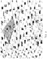
- Fig. 3 discloses one way of using the construction panel 100 in that it is attached to a grid-like structure 124 such that it is inserted into the square spaced defined by this structure 124. It will be appreciated that in this way, the construction panel 100 may be moved from one square space to another.
- Fig. 4 discloses another way of using the construction panel 100 in that the panel it self is suspended from the ceiling 126 by means of wires. This provides the advantage that the construction panel 100 may be positioned closer to e.g. a table.
- a plurality of light emitters are provided which defines a first zone which is encirculated by a second zone of light emitters.
- the beam angle of the light emitters of the first zone is wider than the beam angle of the light emitters of the second zone.
- the beam angle of the light emitters of the first zone is narrower than the beam angle of the light emitters of the second zone.
Landscapes
- Engineering & Computer Science (AREA)
- General Engineering & Computer Science (AREA)
- Illuminated Signs And Luminous Advertising (AREA)
- Arrangement Of Elements, Cooling, Sealing, Or The Like Of Lighting Devices (AREA)
Applications Claiming Priority (1)
| Application Number | Priority Date | Filing Date | Title |
|---|---|---|---|
| DKPA201170049 | 2011-01-27 |
Publications (2)
| Publication Number | Publication Date |
|---|---|
| EP2485342A2 true EP2485342A2 (de) | 2012-08-08 |
| EP2485342A3 EP2485342A3 (de) | 2014-06-11 |
Family
ID=45581732
Family Applications (1)
| Application Number | Title | Priority Date | Filing Date |
|---|---|---|---|
| EP12152704.8A Withdrawn EP2485342A3 (de) | 2011-01-27 | 2012-01-26 | Bauplatte und Verfahren zum Befestigen eines Lichtsenders daran |
Country Status (1)
| Country | Link |
|---|---|
| EP (1) | EP2485342A3 (de) |
Cited By (4)
| Publication number | Priority date | Publication date | Assignee | Title |
|---|---|---|---|---|
| US9587812B2 (en) | 2014-01-10 | 2017-03-07 | Led Ibond International Aps | Construction element with at least one electronic component and associated method |
| WO2018077359A1 (en) | 2016-10-31 | 2018-05-03 | Led Ibond International Aps | Electrical supply system |
| US10267504B2 (en) | 2016-01-11 | 2019-04-23 | Led Ibond International Aps | Electrical supply module for flexible coupling |
| WO2023041136A1 (en) | 2021-09-20 | 2023-03-23 | LED iBond International A/S | An led plug |
Citations (2)
| Publication number | Priority date | Publication date | Assignee | Title |
|---|---|---|---|---|
| WO2003017435A1 (en) | 2001-08-13 | 2003-02-27 | Didriksen, Torben | Adapter for power transfer |
| WO2009076960A1 (en) | 2007-12-17 | 2009-06-25 | Ledlumina Technology A/S | Adapter with at least one electronic component |
Family Cites Families (4)
| Publication number | Priority date | Publication date | Assignee | Title |
|---|---|---|---|---|
| DE19911860A1 (de) * | 1999-03-17 | 2000-12-28 | Werner Vidoni | Beleuchtbare Dekorationsplatte |
| US6657381B1 (en) * | 1999-12-13 | 2003-12-02 | Makoto Arutaki | Display device having a multi-layered structure with light-emitting devices mounted thereon |
| EP1841013A1 (de) * | 2006-03-30 | 2007-10-03 | Ueli Egger | Beleuchtungseinrichtung |
| US8525402B2 (en) * | 2006-09-11 | 2013-09-03 | 3M Innovative Properties Company | Illumination devices and methods for making the same |
-
2012
- 2012-01-26 EP EP12152704.8A patent/EP2485342A3/de not_active Withdrawn
Patent Citations (2)
| Publication number | Priority date | Publication date | Assignee | Title |
|---|---|---|---|---|
| WO2003017435A1 (en) | 2001-08-13 | 2003-02-27 | Didriksen, Torben | Adapter for power transfer |
| WO2009076960A1 (en) | 2007-12-17 | 2009-06-25 | Ledlumina Technology A/S | Adapter with at least one electronic component |
Cited By (7)
| Publication number | Priority date | Publication date | Assignee | Title |
|---|---|---|---|---|
| US9587812B2 (en) | 2014-01-10 | 2017-03-07 | Led Ibond International Aps | Construction element with at least one electronic component and associated method |
| US9874339B2 (en) | 2014-01-10 | 2018-01-23 | Led Ibond International Aps | Construction element with at least one electronic component and associated method |
| US10267504B2 (en) | 2016-01-11 | 2019-04-23 | Led Ibond International Aps | Electrical supply module for flexible coupling |
| WO2018077359A1 (en) | 2016-10-31 | 2018-05-03 | Led Ibond International Aps | Electrical supply system |
| US10535967B2 (en) | 2016-10-31 | 2020-01-14 | Led Ibond International Aps | Electrical supply system |
| WO2023041136A1 (en) | 2021-09-20 | 2023-03-23 | LED iBond International A/S | An led plug |
| US12379097B2 (en) | 2021-09-20 | 2025-08-05 | LED iBond International A/S | Electrical plug for connecting to a substrate |
Also Published As
| Publication number | Publication date |
|---|---|
| EP2485342A3 (de) | 2014-06-11 |
Similar Documents
| Publication | Publication Date | Title |
|---|---|---|
| EP2485342A2 (de) | Bauplatte und Verfahren zum Befestigen eines Lichtsenders daran | |
| ES2567586T3 (es) | Estructura termomecánica adaptada para un entorno espacial | |
| EP3094923B1 (de) | Bauelement mit mindestens einem elektronischen bauteil und ein zugehöriges arbeitsverfahren | |
| US20150292692A1 (en) | Lighting device, insertion and receiving element | |
| JP6850307B2 (ja) | 乗り物のための発光する積層グレージングルーフとそれを組み込んだ乗り物及び前記グレージングルーフの製造 | |
| CN108700284B (zh) | 供电模块 | |
| CN105940259A (zh) | Led灯泡 | |
| CN103574404A (zh) | 照明装置 | |
| US20140165369A1 (en) | Threaded insert with thermal insulation capability | |
| EP3532772B1 (de) | Energieversorgungsmodul | |
| ES2600524T3 (es) | Dispositivo para fijar módulos solares en una fachada | |
| JP6826374B2 (ja) | 蓄熱体を備えた複合建材及びその製造方法 | |
| WO2008136472A1 (ja) | 分析システム | |
| JP4038497B2 (ja) | 断熱性パネル | |
| KR20180081651A (ko) | 조립식 마감패널 | |
| CN109750784B (zh) | 一种用于防止灯槽直角开裂的灯槽吊顶直角模块及施工方法 | |
| EP2573460A2 (de) | Lichtquelleneinheit, Lichtquellenvorrichtung mit Lichtquelleneinheit und Lampe mit der Lichtquellenvorrichtung | |
| EP3020031A1 (de) | Sicherheitssystem | |
| EP2138754A2 (de) | Beleuchtung, die eine verbesserte Tragestruktur umfasst | |
| CN215001023U (zh) | 一种用于植物生长灯的铝基板 | |
| CN103796454A (zh) | 一种灯具电源盒 | |
| JP5967575B2 (ja) | 固定具、及びこれを用いた二層構造パネル体の取付構造 | |
| EP2860443B1 (de) | Leuchtendes Anzeigegerät | |
| EP1689945B1 (de) | Elektrisch leitendes bauelement, gebäude und verfahren zum errichten des gebäudes | |
| CN204026204U (zh) | Led灯 |
Legal Events
| Date | Code | Title | Description |
|---|---|---|---|
| PUAI | Public reference made under article 153(3) epc to a published international application that has entered the european phase |
Free format text: ORIGINAL CODE: 0009012 |
|
| AK | Designated contracting states |
Kind code of ref document: A2 Designated state(s): AL AT BE BG CH CY CZ DE DK EE ES FI FR GB GR HR HU IE IS IT LI LT LU LV MC MK MT NL NO PL PT RO RS SE SI SK SM TR |
|
| AX | Request for extension of the european patent |
Extension state: BA ME |
|
| RAP1 | Party data changed (applicant data changed or rights of an application transferred) |
Owner name: SCANLED IPR APS |
|
| PUAL | Search report despatched |
Free format text: ORIGINAL CODE: 0009013 |
|
| RIC1 | Information provided on ipc code assigned before grant |
Ipc: H01R 33/06 20060101ALN20140430BHEP Ipc: H01R 25/14 20060101AFI20140430BHEP Ipc: F21S 8/04 20060101ALI20140430BHEP Ipc: F21S 8/06 20060101ALI20140430BHEP |
|
| AK | Designated contracting states |
Kind code of ref document: A3 Designated state(s): AL AT BE BG CH CY CZ DE DK EE ES FI FR GB GR HR HU IE IS IT LI LT LU LV MC MK MT NL NO PL PT RO RS SE SI SK SM TR |
|
| AX | Request for extension of the european patent |
Extension state: BA ME |
|
| STAA | Information on the status of an ep patent application or granted ep patent |
Free format text: STATUS: THE APPLICATION IS DEEMED TO BE WITHDRAWN |
|
| 18D | Application deemed to be withdrawn |
Effective date: 20141212 |