EP2138754A2 - Beleuchtung, die eine verbesserte Tragestruktur umfasst - Google Patents
Beleuchtung, die eine verbesserte Tragestruktur umfasst Download PDFInfo
- Publication number
- EP2138754A2 EP2138754A2 EP09007936A EP09007936A EP2138754A2 EP 2138754 A2 EP2138754 A2 EP 2138754A2 EP 09007936 A EP09007936 A EP 09007936A EP 09007936 A EP09007936 A EP 09007936A EP 2138754 A2 EP2138754 A2 EP 2138754A2
- Authority
- EP
- European Patent Office
- Prior art keywords
- pipe
- illumination
- supporting structure
- pex
- pipes
- Prior art date
- Legal status (The legal status is an assumption and is not a legal conclusion. Google has not performed a legal analysis and makes no representation as to the accuracy of the status listed.)
- Withdrawn
Links
Images


Classifications
-
- F—MECHANICAL ENGINEERING; LIGHTING; HEATING; WEAPONS; BLASTING
- F21—LIGHTING
- F21V—FUNCTIONAL FEATURES OR DETAILS OF LIGHTING DEVICES OR SYSTEMS THEREOF; STRUCTURAL COMBINATIONS OF LIGHTING DEVICES WITH OTHER ARTICLES, NOT OTHERWISE PROVIDED FOR
- F21V21/00—Supporting, suspending, or attaching arrangements for lighting devices; Hand grips
- F21V21/08—Devices for easy attachment to any desired place, e.g. clip, clamp, magnet
- F21V21/088—Clips; Clamps
-
- F—MECHANICAL ENGINEERING; LIGHTING; HEATING; WEAPONS; BLASTING
- F21—LIGHTING
- F21S—NON-PORTABLE LIGHTING DEVICES; SYSTEMS THEREOF; VEHICLE LIGHTING DEVICES SPECIALLY ADAPTED FOR VEHICLE EXTERIORS
- F21S4/00—Lighting devices or systems using a string or strip of light sources
- F21S4/10—Lighting devices or systems using a string or strip of light sources with light sources attached to loose electric cables, e.g. Christmas tree lights
-
- F—MECHANICAL ENGINEERING; LIGHTING; HEATING; WEAPONS; BLASTING
- F21—LIGHTING
- F21S—NON-PORTABLE LIGHTING DEVICES; SYSTEMS THEREOF; VEHICLE LIGHTING DEVICES SPECIALLY ADAPTED FOR VEHICLE EXTERIORS
- F21S4/00—Lighting devices or systems using a string or strip of light sources
- F21S4/20—Lighting devices or systems using a string or strip of light sources with light sources held by or within elongate supports
-
- F—MECHANICAL ENGINEERING; LIGHTING; HEATING; WEAPONS; BLASTING
- F21—LIGHTING
- F21V—FUNCTIONAL FEATURES OR DETAILS OF LIGHTING DEVICES OR SYSTEMS THEREOF; STRUCTURAL COMBINATIONS OF LIGHTING DEVICES WITH OTHER ARTICLES, NOT OTHERWISE PROVIDED FOR
- F21V21/00—Supporting, suspending, or attaching arrangements for lighting devices; Hand grips
- F21V21/002—Supporting, suspending, or attaching arrangements for lighting devices; Hand grips making direct electrical contact, e.g. by piercing
-
- F—MECHANICAL ENGINEERING; LIGHTING; HEATING; WEAPONS; BLASTING
- F21—LIGHTING
- F21W—INDEXING SCHEME ASSOCIATED WITH SUBCLASSES F21K, F21L, F21S and F21V, RELATING TO USES OR APPLICATIONS OF LIGHTING DEVICES OR SYSTEMS
- F21W2121/00—Use or application of lighting devices or systems for decorative purposes, not provided for in codes F21W2102/00 – F21W2107/00
-
- F—MECHANICAL ENGINEERING; LIGHTING; HEATING; WEAPONS; BLASTING
- F21—LIGHTING
- F21Y—INDEXING SCHEME ASSOCIATED WITH SUBCLASSES F21K, F21L, F21S and F21V, RELATING TO THE FORM OR THE KIND OF THE LIGHT SOURCES OR OF THE COLOUR OF THE LIGHT EMITTED
- F21Y2115/00—Light-generating elements of semiconductor light sources
- F21Y2115/10—Light-emitting diodes [LED]
Definitions
- the present invention relates to an illumination comprising a supporting structure of the type described in the preamble of Claim 1.
- Illuminations realized by a supporting structure which supports a plurality of low voltage electrical light bulbs are currently known.
- illuminations have shapes and structures that vary according to the festival and the subject represented.
- the supporting structures of illuminations are commonly made of wood.
- wood is easily machined using small automatic or manual tools.
- a plurality of wooden segments are mutually bonded, forming the supporting structure on which light bulbs or the like are positioned.
- prior art structures are not able to support illuminations having very large dimensions, for example illuminations extending transversely across the entire road, and which are connected to the ground at the end of the road.
- Prior art supporting structures can also be made of metal.
- the technical aim of the present invention is to devise an illumination comprising a supporting structure capable of substantially overcoming the aforesaid drawbacks.
- an important object of the invention is to obtain an illumination comprising a supporting structure that is simple to fashion.
- Another important object of the invention is to produce an illumination comprising a supporting structure that can withstand high mechanical and physical loads.
- a further object of the invention is to produce an illumination comprising a supporting structure that is not inflammable and does not conduct electrical current.
- the illumination according to the invention is indicated as a whole with the number 1 .
- It comprises a supporting structure 2 suitable to support at least one lighting unit 3.
- the supporting structure 2 comprises at least one pipe 4 having an outer layer 5 made of polymeric material, realizing the surface of the pipe 4, and a metal layer 6 made of metallic material.
- the pipe 4 preferably comprises an inner layer 7, realizing the inner surface of the pipe 4 and is also made of polymeric material. Consequently, the metal layer 6 is enclosed inside the layers 5 and 7 made of polymeric material.
- layers of adhesive material 8 suitable to physically connect the metal layer 6 to the layers 5 and 7 made of polymeric material, are preferably positioned between the layers 5 and 7 and the inner layer 6.
- the metal layer 6 has a thickness of between 0.1 mm and 2 mm, a diameter of between 1 cm and 3 cm and is made of manually deformable metal, such as in particular aluminium alloys, or copper alloys, brass alloys and the like.
- the layers 5 and 7 made of polymeric material instead have a thickness of between 0.1 mm and 5 mm, a diameter such as to surround the metal layer 6 and are preferably made of Polyethylene, in more detail cross-linked polyethylene (known with the initials PEX).
- the pipe 4 is then preferably of the type realized by pipes known with the term multilayer pipes, and in particular " PEX-AL-PEX" multilayer pipes, used to convey water in buildings and the like and therefore intended for different applications not pertinent to the present use.
- the lighting units 3 are preferably realized by incandescent or gas bulbs or by
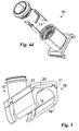
- the lighting units 3 are supported by a supporting device 10 , as shown in Figs. 4a-4c and 5 , suitable to connect to the electrical cables 9, to physically support the lighting units 3 and to connect them electrically to the electrical cables 9.
- the supporting devices 10 can then comprise electrical connections 11 , positioned in proximity of the outer surface of the pipes 4 and suitable to electrically connect the device 10 to the electrical cables 9.
- the electrical connections 11 advantageously comprise a plurality of through holes 11a for electrical cables, preferably four, suitable to allow passage of the electrical cables 9 connected to the lighting unit 3 constrained to the supporting device 10.
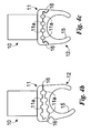
- the electrical connections 11 are also preferably openable, so as to allow the through holes 11 a to be easily reached. Opening of the electrical connections 11 is advantageously regulated by specific opening means 16 of the electrical connections 11, such as two joints ( Fig. 4c ) or one joint and one hinge ( Fig. 4b ).
- the device 10 is furthermore illustrated in Fig. 4d .
- the supporting devices 10 also comprise a coupling portion 12 positioned on the interface surface with the pipes 4.
- the coupling portion 12 comprises a surface substantially counter-shaped to an angular portion of the pipe 4 and also at least one connector 13, and preferably two connectors 13, suitable to be inserted in specific holes or the like present in the pipes 4, as shown in Fig. 4a .
- the connectors 4, shown in Fig. 4a advantageously have a conical shape, so as to be inserted simply in the holes and remain constrained thereto.
- the coupling portion 12 can comprise a coupler 15 partly cylindrical and suitable to couple with the outer surface of the pipe 4, as shown in Figs. 4b, 4c and 5 .
- the supporting structure 2 can also comprise cable grommet elements 17, suitable to keep cables together and prevent their dispersal, as shown in Fig. 5 .
- the cable grommet elements comprise a coupling element 18 , analogous to the coupling portion 12 of the supporting devices 10 and in particular comprising a further coupler 19 , analogous to the coupler 15 of the supporting devices 10.
- the cable grommet elements also comprise at least one grommet hole 20, suitable to allow the passage of at least one electrical cable 9.
- the grommet hole 20 is also preferably openable, to allow it to be easily reached. Opening thereof is preferably regulated by second opening means 21, in particular by two joints or by a hinge or the like.
- the cable grommet elements 18 are preferably positioned in proximity of the supporting devices 10, as shown in Fig. 5 .
- the supporting structure 2 preferably comprises a plurality of pipes 4.
- Said pipes 4 can be mutually connected by means of specific joining elements 14, shown by way of example in Fig. 3 .
- the joining elements 14 are preferably realized by two portions with mirror symmetry, closable by means of releasable joining means, such as screws and the like, and including two seats counter-shaped to the pipes 4.
- the illumination 1 can also comprise second joining elements, not shown, having a first portion suitable to be constrained to a pipe 4 and a second portion suitable to be constrained to the ground or to an external pole or the like.
- the assembler shapes the pipes 4 to produce said shape, either manually or using simple tools. They can also be cut by means of saws or the like.
- the pipes 4 are mutually connected by means of joining elements 14 or connected to the ground or to other elements by means of the second joining elements.
- the lighting units 3 are also connected to the pipes 4 by means of the coupling portions 12 and in particular of the connectors 13 positioned in the holes in the pipes 4. These latter can be produced before or after positioning of the supporting structure 2.
- the lighting units 3 are also connected to the electrical supply or to a generator or to batteries by means of the electrical cables 9 and the electrical connections present on the supporting devices 10.
- the illuminations 1 function substantially in the same manner as conventional illuminations.
- the invention comprises a new process for producing illuminations 1 of the type described.
- This provides for the production of a supporting structure 2 by means of pipes 4, of the type described previously, and subsequent application of lighting units 3, preferably by means of the described supporting devices 10.
- the supporting structure 2 can also be produced by means of the described joining elements 14.
- the invention also teaches a new use of a multilayer pipe 4, described previously, to produce a supporting structure 2 for illuminations 1.
- the invention achieves important advantages.
- the illumination 1 including the supporting structure 2 can be fashioned manually and simply and can allow the production of arches of dimensions of over ten metres.
- the pipes 4 withstand high mechanical loads and have a very low linear weight.
- these pipes 4 have external and internal surfaces made of polymeric materials and are therefore resistant to corrosion, for example caused by rain and acid rain, and to other chemical substances.
- the pipes 4 are also insulated from electrical current and guaranteed fireproof.
- the invention is susceptible to modifications and variants falling within the inventive concept.
- the electrical cables 9 can be placed inside the pipes 4.
Landscapes
- Engineering & Computer Science (AREA)
- General Engineering & Computer Science (AREA)
- Non-Portable Lighting Devices Or Systems Thereof (AREA)
- Materials For Medical Uses (AREA)
- Medicines Containing Material From Animals Or Micro-Organisms (AREA)
- Laminated Bodies (AREA)
Applications Claiming Priority (1)
| Application Number | Priority Date | Filing Date | Title |
|---|---|---|---|
| IT001182A ITMI20081182A1 (it) | 2008-06-27 | 2008-06-27 | Luminaria comprendente una struttura di sostegno perfezionata |
Publications (2)
| Publication Number | Publication Date |
|---|---|
| EP2138754A2 true EP2138754A2 (de) | 2009-12-30 |
| EP2138754A3 EP2138754A3 (de) | 2012-01-04 |
Family
ID=40301882
Family Applications (1)
| Application Number | Title | Priority Date | Filing Date |
|---|---|---|---|
| EP09007936A Withdrawn EP2138754A3 (de) | 2008-06-27 | 2009-06-17 | Beleuchtung, die eine verbesserte Tragestruktur umfasst |
Country Status (2)
| Country | Link |
|---|---|
| EP (1) | EP2138754A3 (de) |
| IT (1) | ITMI20081182A1 (de) |
Cited By (2)
| Publication number | Priority date | Publication date | Assignee | Title |
|---|---|---|---|---|
| FR2996283A1 (fr) * | 2012-10-02 | 2014-04-04 | Nicolas Pichelin | Luminaire a tete de lampe orientable |
| CN111055973A (zh) * | 2019-12-11 | 2020-04-24 | 澳龙船艇科技有限公司 | 船舶亮化方法和结构 |
Family Cites Families (6)
| Publication number | Priority date | Publication date | Assignee | Title |
|---|---|---|---|---|
| US5336536A (en) * | 1993-03-31 | 1994-08-09 | Oberzan August J | Collapsible cone structure |
| DE29616093U1 (de) * | 1996-09-16 | 1996-10-31 | Wei, Jung-Kuei, Lung Tan Hsiang, Taoyuan | Haltevorrichtung für Lampen |
| GR1003632B (el) * | 2000-10-12 | 2001-07-30 | Πλαισιο για διακοσμητικες παραστασεις δρομων, στυλων, πλατειων και καταστηματων | |
| US6547418B1 (en) * | 2001-10-31 | 2003-04-15 | Yen Chuan Hsu | Structure of tube lamp |
| NL1019778C2 (nl) * | 2002-01-18 | 2003-07-21 | Fibrallicht B V | Inrichting voor het uitstralen van licht. |
| US6846094B2 (en) * | 2002-08-26 | 2005-01-25 | Altman Stage Lighting, Co., Inc. | Flexible LED lighting strip |
-
2008
- 2008-06-27 IT IT001182A patent/ITMI20081182A1/it unknown
-
2009
- 2009-06-17 EP EP09007936A patent/EP2138754A3/de not_active Withdrawn
Cited By (3)
| Publication number | Priority date | Publication date | Assignee | Title |
|---|---|---|---|---|
| FR2996283A1 (fr) * | 2012-10-02 | 2014-04-04 | Nicolas Pichelin | Luminaire a tete de lampe orientable |
| WO2014053545A1 (fr) * | 2012-10-02 | 2014-04-10 | Nicolas Pichelin | Luminaire a tete de lampe orientable |
| CN111055973A (zh) * | 2019-12-11 | 2020-04-24 | 澳龙船艇科技有限公司 | 船舶亮化方法和结构 |
Also Published As
| Publication number | Publication date |
|---|---|
| ITMI20081182A1 (it) | 2009-12-28 |
| EP2138754A3 (de) | 2012-01-04 |
Similar Documents
| Publication | Publication Date | Title |
|---|---|---|
| US10036541B2 (en) | Canopy for a modular lighting system | |
| US8714775B2 (en) | Light fixtures, methods of suspending a plurality of light sources, an ornament mounting, and a method for mounting an ornament | |
| US6634766B1 (en) | Ornamental lighting | |
| US7938565B2 (en) | Outdoor light apparatus and assembly | |
| CN106415115A (zh) | 照明系统 | |
| US9851054B2 (en) | Universal lamp support | |
| US6971768B1 (en) | Decorative lighting system | |
| EP2138754A2 (de) | Beleuchtung, die eine verbesserte Tragestruktur umfasst | |
| US20080285291A1 (en) | Recessed light retrofit kit | |
| JP2014035967A (ja) | 仮設照明システム | |
| DE102009036382A1 (de) | Lichtplattensystem aus Lichtplattenelementen für horizontal bis vertikal zu verlegende Belag-/ Stein- Ebenen und ihre Verschaltung | |
| CN212273811U (zh) | Led灯具连接装置 | |
| JP3187020U (ja) | Led照明器具 | |
| JP2021068688A (ja) | 広告灯 | |
| US20150369465A1 (en) | Lighting system | |
| US20060279958A1 (en) | Apparatus and method for providing attachment of magnetic devices in a decorative lighting system | |
| ITMI20130990A1 (it) | Dispositivo di illuminazione e gruppo di illuminazione comprendente detto dispositvo di illuminazione | |
| US10072803B1 (en) | Electrical device | |
| EP2577152A2 (de) | Beleuchtungsanordnung für ein deckenbrett | |
| KR200389277Y1 (ko) | 직관형광등기구들의 등간 연결구 | |
| KR20250095037A (ko) | 조명이 결합된 놀이시설물 및 이의 제조 방법 | |
| KR100332963B1 (ko) | 건물배선용 리셉터클 | |
| KR200364828Y1 (ko) | 샹들리에용 암의 결합구조 | |
| JP3166323U (ja) | 建築天井フレームのバー構造 | |
| TW200847571A (en) | Double-board combinational type bus line power supply device |
Legal Events
| Date | Code | Title | Description |
|---|---|---|---|
| PUAI | Public reference made under article 153(3) epc to a published international application that has entered the european phase |
Free format text: ORIGINAL CODE: 0009012 |
|
| AK | Designated contracting states |
Kind code of ref document: A2 Designated state(s): AT BE BG CH CY CZ DE DK EE ES FI FR GB GR HR HU IE IS IT LI LT LU LV MC MK MT NL NO PL PT RO SE SI SK TR |
|
| PUAL | Search report despatched |
Free format text: ORIGINAL CODE: 0009013 |
|
| AK | Designated contracting states |
Kind code of ref document: A3 Designated state(s): AT BE BG CH CY CZ DE DK EE ES FI FR GB GR HR HU IE IS IT LI LT LU LV MC MK MT NL NO PL PT RO SE SI SK TR |
|
| AX | Request for extension of the european patent |
Extension state: AL BA RS |
|
| RIC1 | Information provided on ipc code assigned before grant |
Ipc: F21Y 101/02 20060101ALN20111129BHEP Ipc: F21W 121/00 20060101ALN20111129BHEP Ipc: F21V 21/088 20060101ALN20111129BHEP Ipc: F21V 21/002 20060101ALN20111129BHEP Ipc: F21V 21/00 20060101ALI20111129BHEP Ipc: F21S 4/00 20060101AFI20111129BHEP |
|
| STAA | Information on the status of an ep patent application or granted ep patent |
Free format text: STATUS: THE APPLICATION IS DEEMED TO BE WITHDRAWN |
|
| 18D | Application deemed to be withdrawn |
Effective date: 20120705 |