EP2485043B1 - Vorrichtung und testverfahren zum testen von electrochemischen sensoren - Google Patents
Vorrichtung und testverfahren zum testen von electrochemischen sensoren Download PDFInfo
- Publication number
- EP2485043B1 EP2485043B1 EP12153538.9A EP12153538A EP2485043B1 EP 2485043 B1 EP2485043 B1 EP 2485043B1 EP 12153538 A EP12153538 A EP 12153538A EP 2485043 B1 EP2485043 B1 EP 2485043B1
- Authority
- EP
- European Patent Office
- Prior art keywords
- voltage
- electrode
- response
- current
- time
- Prior art date
- Legal status (The legal status is an assumption and is not a legal conclusion. Google has not performed a legal analysis and makes no representation as to the accuracy of the status listed.)
- Active
Links
Images








Classifications
-
- G—PHYSICS
- G01—MEASURING; TESTING
- G01N—INVESTIGATING OR ANALYSING MATERIALS BY DETERMINING THEIR CHEMICAL OR PHYSICAL PROPERTIES
- G01N27/00—Investigating or analysing materials by the use of electric, electrochemical, or magnetic means
- G01N27/26—Investigating or analysing materials by the use of electric, electrochemical, or magnetic means by investigating electrochemical variables; by using electrolysis or electrophoresis
- G01N27/28—Electrolytic cell components
- G01N27/30—Electrodes, e.g. test electrodes; Half-cells
- G01N27/327—Biochemical electrodes, e.g. electrical or mechanical details for in vitro measurements
- G01N27/3271—Amperometric enzyme electrodes for analytes in body fluids, e.g. glucose in blood
- G01N27/3274—Corrective measures, e.g. error detection, compensation for temperature or hematocrit, calibration
-
- A—HUMAN NECESSITIES
- A61—MEDICAL OR VETERINARY SCIENCE; HYGIENE
- A61B—DIAGNOSIS; SURGERY; IDENTIFICATION
- A61B5/00—Measuring for diagnostic purposes; Identification of persons
- A61B5/145—Measuring characteristics of blood in vivo, e.g. gas concentration or pH-value ; Measuring characteristics of body fluids or tissues, e.g. interstitial fluid or cerebral tissue
- A61B5/14532—Measuring characteristics of blood in vivo, e.g. gas concentration or pH-value ; Measuring characteristics of body fluids or tissues, e.g. interstitial fluid or cerebral tissue for measuring glucose, e.g. by tissue impedance measurement
-
- A—HUMAN NECESSITIES
- A61—MEDICAL OR VETERINARY SCIENCE; HYGIENE
- A61B—DIAGNOSIS; SURGERY; IDENTIFICATION
- A61B5/00—Measuring for diagnostic purposes; Identification of persons
- A61B5/145—Measuring characteristics of blood in vivo, e.g. gas concentration or pH-value ; Measuring characteristics of body fluids or tissues, e.g. interstitial fluid or cerebral tissue
- A61B5/1468—Measuring characteristics of blood in vivo, e.g. gas concentration or pH-value ; Measuring characteristics of body fluids or tissues, e.g. interstitial fluid or cerebral tissue using chemical or electrochemical methods, e.g. by polarographic means
- A61B5/1486—Measuring characteristics of blood in vivo, e.g. gas concentration or pH-value ; Measuring characteristics of body fluids or tissues, e.g. interstitial fluid or cerebral tissue using chemical or electrochemical methods, e.g. by polarographic means using enzyme electrodes, e.g. with immobilised oxidase
Definitions
- the present invention relates to an analyzing device, a sensor testing device, testing method and computer-readable storage medium.
- EP 1 455 182 A1 discloses an analyzer including a current measurer for measuring the current flowing between paired electrodes when a sample is introduced to the reagent layer of a sensor and voltage is applied across the electrodes, while also including a processor for analyzing the sample based on the current after a predetermined reference time point.
- the analyzer further includes a fail determiner which monitors the change of the current before and after the reference time point and determines that the sensor is improper when the current change does not correspond to a predetermined current change.
- JP 2004 233294 A discloses an electrochemical sensor comprising two electrodes or three electrodes mounted on an electrochemical sensor measuring device.
- a constant voltage is applied to a working electrode and a reference electrode, and a current flowing between the working electrode and a counter electrode is detected.
- a transient response time until the current reaches the steady state is counted, and the sensor quality is determined on reference to the relation between the transient response time and the calibration value.
- the present invention is a sensor testing device as defined in Claim 1 of the appended claims. Also provided is an analyzing device as defined in Claim 2, a sensor testing method as defined in Claim 13, a sensor testing program as defined in Claim 14, and a computer-readable storage medium as defined in Claim 15.
- embodiments of the invention are directed towards an analyzing device capable of stably testing the state of a sensor in a short time, without providing plural electrode sets, and to a sensor testing device, testing method and computer-readable storage medium of the same.
- a sensor section has a reagent layer including a reagent that reacts with a substance in a sample liquid, an electrode including a first electrode and a second electrode for applying a voltage to the reagent layer, and an external layer membrane for making contact with the reagent layer.
- a current measurement unit measures current flowing between the first electrode and the second electrode.
- the determination unit determines whether or not there is a defect present in the external layer membrane based on at least one of a first physical quantity related to an amount of change per specific period of time of a first current measured by the current measurement unit when the first voltage has been applied and a second physical quantity related to an amount of change per specific period of time of a second current measured by the current measurement unit when the second voltage has been applied.
- the first physical quantity and the second physical quantity may be amount of change per specific period of time of the respective currents themselves, or other physical quantities that can be derived therefrom.
- the state of the sensor can be tested stably and in a short time without providing plural sets of electrodes.
- the first physical quantity may be a first time from until the amount of change per specific period of time of the first current reaches a value in a predetermined first specific range and the second physical quantity may be a second time until the amount of change per specific period of time of the second current reaches a value in a predetermined second specific range.
- the analyzing device may further include a correction unit that corrects the current value measured by the current measurement unit when a defect is determined by the determination unit to have occurred in the external layer membrane, the correction unit performing correction based on at least one of a predetermined first relationship between the first physical quantity and a defect ratio of the external layer membrane and a predetermined second relationship between the second physical quantity and a defect ratio of the external layer membrane.
- the first physical quantity and the second physical quantity obtained when the first voltage and the second voltage are respectively applied change in response to the defect ratio of the external layer membrane. Therefore, the measured current value can be corrected based on the defect ratio derived from these physical quantities.
- the correction unit may estimate the defect ratio based on at least one of the first relationship and the second relationship, and correct the current value measured by the current measurement unit based on a predetermined relationship between the defect ratio of the external layer membrane and the current value measured from the sensor section provided with an external layer membrane having defects corresponding to the defect ratio.
- the correction unit may compute the defect ratio as the average value, the maximum value or the minimum value of a first defect ratio estimated based on the first relationship and a second defect ratio estimated based on the second relationship.
- the analyzing device may further include an output unit that outputs a signal indicating that a defect has occurred in the sensor section when a defect is determined to have occurred in the external layer membrane by the determination unit.
- the voltage application unit when applying both the first voltage and the second voltage the voltage application unit may apply the first voltage and the second voltage alternately.
- the current measurement unit may continuously measure the current flowing between the first electrode and the second electrode, and the determination unit may determine the presence or absence of a defect in the external layer membrane at a predetermined timing. Since it is desirable to be able to test the sensor in a short time in a device that continuously monitors current in this manner such as, for example, in a continuous blood sugar monitoring device, application of the analyzing device of the present invention is highly effective.
- the senor section may be disposed under the skin of a user of the analyzing device and the reagent layer reacts to a composition to be tested present under the skin.
- the reagent layer may extract electrons from the composition to be tested and may supply the extracted electrons to the electrode.
- the reagent layer may include an enzyme portion for extracting electrons from the composition to be tested.
- the present sensor testing device can, for instance, be employed to test the state of the external layer membrane of sensors in a sensor manufacturing process, such as in a factory where sensors are being manufactured.
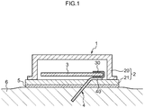
- a continuous glucose monitoring device 1 of the present exemplary embodiment is configured including a housing 2, a circuit board 3, and a sensor section 4.
- the continuous glucose monitoring device 1 is applied to skin 6 such as an abdominal or shoulder region of a human body, and continuously monitors the concentration of glucose in the blood or in interstitial subcutaneous fluid.
- the housing 2 is configured with a cover 20 and a base 21 forming the external profile of the continuous glucose monitoring device 1.
- the cover 20 and the base 21 are joined together so as to house the circuit board 3 in the space formed between the cover 20 and the base 21.
- a material with extremely low moisture transmissivity for example a metal or a polypropylene resin, is preferably employed for the housing 2.
- the base 21 is formed with an insertion hole for inserting the sensor section 4, and an end portion 40 of the sensor section 4 is fixed at the inside face of the base 21.
- a bonding film 5 is provided on the outside face of the base 21.
- An adhesive tape is employed on both faces of the bonding film 5.
- the bonding film 5 is itself attached to the base 21 through the tape on one face, and the continuous glucose monitoring device 1 is attached to the skin 6 through the tape on the other face.
- the circuit board 3 is equipped with electronic configuration elements required for overall control of the continuous glucose monitoring device 1.
- the circuit board 3 is configured including a connection portion 30 for making contact with an electrode 42 (see Fig. 2 ) of the sensor section 4, described later.
- the connection portion 30 is employed to apply a voltage to the sensor section 4 and obtain a response current.
- the sensor section 4 obtains a response that depends on the glucose concentration in the blood or interstitial subcutaneous fluid.
- a first end portion 40 of the sensor section 4 makes contact with the connection portion 30 of the circuit board 3, and the second end portion of the sensor section 4 is inserted into the skin 6.
- the sensor section 4 is configured including a base 41, the electrode 42 and an enzyme portion 43.
- the base 41 is configured in sheet form from a flexible, electrically insulating material and supports the electrode 42.
- An end portion 41B of the base 41 on the side for insertion into the skin 6 is formed with a sharp profile, enabling the sensor section 4 to be easily inserted into the skin 6 and enabling pain of a user to be reduced.
- a material that has appropriate electrical insulating properties so as not to affect the human body can be employed as the material for the base 41, and, for example, a thermoplastic resin such as polyethylene terephthalate (PET), polypropylene (PP) or polyethylene (PE) may be employed therefor.
- a thermoset resin such as a polyimide resin or an epoxy resin may also be employed therefor.
- the electrode 42 is configured including a working electrode portion 42A and a counter electrode portion 42B. By applying a voltage to the electrode 42 a current flows between the working electrode portion 42A and the counter electrode portion 42B corresponding to electrons extracted by the enzyme portion 43, described later.
- the enzyme portion 43 acts to extract electrons from the glucose and pass the extracted electrons across to the working electrode portion 42A.
- the enzyme portion 43 can, for example, be a glucose oxidoreductase disposed on the working electrode portion 42A.
- a glucose oxidase (GOD) or a glucose dehydrogenase (GDH) can be employed as the glucose oxidoreductase.
- a known method can be employed as the method for affixing the glucose oxidoreductase, such as for example employing a method that uses a polymerizable gel, polyacrylamide, or a polymer such as phosphorus, a method that uses a MPC polymer of a phospholipid polymer coupled using a silane coupling agent, or a method using protein coating.
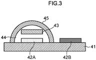
- Fig. 3 schematically illustrates a cross-section configuration of the end portion 41B of the sensor section 4.
- the working electrode portion 42A and the counter electrode portion 42B are formed on the base 41, and a semi-permeable membrane 45 is formed so as to cover the working electrode portion 42A.
- the region configured by the base 41 and the semi-permeable membrane 45 is a reagent layer 44 and the enzyme portion 43 is disposed within the reagent layer 44.
- the enzyme portion 43 need not necessarily be affixed on the working electrode portion 42A, and configuration may be made such that the enzyme portion 43 is disposed within the reagent layer 44, above the working electrode portion 42A but not making contact with the working electrode portion 42A.
- the semi-permeable membrane 45 is provided to prevent sensor sensitivity from becoming saturated immediately, for example to prevent sensitivity saturation to an upper limit of detectable concentration of glucose for the sensor, and the semi-permeable membrane 45 restricts passage of glucose to the enzyme portion 43.
- the semi-permeable membrane 45 also suppresses the passing through to the enzyme portion 43 of interfering substances that would impede reaction.
- a cellulose acetate membrane or polyurethane membrane may be employed as the semi-permeable membrane 45.
- CA membrane a case will be explained in which a cellulose acetate membrane is employed as the semi-permeable membrane 45 (referred to below as CA membrane).
- CA membrane a cellulose acetate membrane
- the semi-permeable membrane 45 is one example of an external membrane in the present invention.
- the external membrane is not limited to materials having a property of restricting passage of glucose to the enzyme portion 43.
- the method of forming the sensor section 4 is by, for example, forming the working electrode portion 42A and the counter electrode portion 42B on the base 41 by screen printing employing a carbon ink, covalent bonding a carbodiimide thereon, dripping a bridged glucose oxidoreductase thereon using glutaraldehyde (GA) as the bridging agent, and then drying with warm air at 40°C for 15 minutes. Then a CA membrane can be formed as the semi-permeable membrane 45 using spin coating or dip coating so as to form a covering. Configuration may also be made with such compounds as a bis (sulphosuccinimidyl) suberate or bis-N-succinimidyl-(nonaethylene glycol) ester.
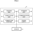
- the circuit board 3 is configured including the connection portion 30 and also a communication unit 31, a power supply 32, a control unit 33, a computation unit 34 and a storage unit 35.
- the communication unit 31 performs data communication between the continuous glucose monitoring device 1 and an external data processing apparatus.
- the communication unit 31 is configured including at least a transmission unit, and as required also includes a reception unit.
- Data communication may be by means of, for example, wireless communication such as infrared communication or Bluetooth. Configuration may also be made such that wired data communication is performed, and in such cases a cable connecting portion is provided to the communication unit 31 of the continuous glucose monitoring device 1, such that data communication is performed by connecting with a cable to an external data processing apparatus, for example.
- Examples of an external data processing apparatus include such an apparatus as an insulin supply device for administering insulin to a human body, a simple blood sugar measurement instrument, a wrist watch size display device, and a personal computer (PC).
- an apparatus as an insulin supply device for administering insulin to a human body, a simple blood sugar measurement instrument, a wrist watch size display device, and a personal computer (PC).
- PC personal computer
- a blood sugar measurement result of the simple blood sugar measurement instrument can be transmitted to the continuous glucose monitoring device 1.
- the measurement result of the continuous glucose monitoring device 1 and the blood sugar measurement result received from the simple blood sugar measurement instrument can accordingly be compared, enabling correction of the measurement results of the continuous glucose monitoring device 1 to be performed.
- Configuration may be made such that the data (current values) measured by the continuous glucose monitoring device 1 are transmitted to the simple blood sugar measurement instrument such that the blood sugar values themselves are computed in the simple blood sugar measurement instrument.
- the measurement result of the continuous glucose monitoring device 1 can be transmitted to the wrist watch size display device.
- Such an approach enables a user to easily ascertain the measurement results even when the continuous glucose monitoring device 1 is mounted to a location that is difficult for a user to see, such as a user's shoulder or abdominal region.
- Data communication between the continuous glucose monitoring device 1 and a PC enables the data (current values) measured by the continuous glucose monitoring device 1 to be transmitted to the PC.
- the glucose concentration trend can be displayed and various analyses can then be performed by the PC.
- Configuration may be made such that correction data or the like is transmitted from a PC to the continuous glucose monitoring device 1.
- the power supply 32 is a direct current power source for supplying power to the circuit board 3 and the sensor section 4, and a battery with a 1 to 3V power supply voltage can be employed, for example.
- the control unit 33 controls the continuous glucose monitoring device 1 overall, controlling, for example, such aspects as the voltage application timing, response current sampling, glucose concentration computation processing and communication to an external data processing apparatus.
- the computation unit 34 executes various computations required in processing in the continuous glucose monitoring device 1, including for example computation of the glucose concentration.
- Programs such as a program for executing a testing mode processing routine, described later, various programs for execution by the control unit 33, and data such as a correction curve, correction data and voltage application patterns employed in computations of the computation unit 34 are stored in the storage unit 35.
- the response current detected by the sensor section 4 and the glucose concentration data computed by the computation unit 34 are also stored in the storage unit 35.
- control unit 33, the computation unit 34 and the storage unit 35 may be configured by electrical components such as a CPU and/or an MPU, ROM and RAM mounted on the circuit board 3.
- the response current is measured when a predetermined voltage pattern, such as illustrated in Fig. 5 , is applied.
- a predetermined voltage pattern such as illustrated in Fig. 5
- the state of the sensor section 4, and in particular the state of the semi-permeable membrane 45 is tested based on changes in response current when a voltage that obtains a response caused by glucose is applied.
- the voltage pattern illustrated in Fig. 5 is a pattern in which a voltage that does not obtain a response caused by glucose (referred to below as non-response voltage E1) is applied for a specific period of time (-200mV for 240 seconds in this example), followed by application of a voltage that obtains a response caused by glucose (referred to below as response voltage E2) for a specific period of time (400mV for 120 seconds in this example).
- non-response voltage E1 a voltage that does not obtain a response caused by glucose
- response voltage E2 a voltage that obtains a response caused by glucose
- the non-response voltage E1 is a voltage to which glucose does not respond at all or a voltage to which glucose exhibits a slight response, but at a level which in practice can be considered as no response. More precisely, the response current when the non-response voltage E1 is applied to the sensor section 4 includes extremely small responses caused by glucose, but is mainly caused by external environmental background factors such as background due to the particularities of the sensor, and background and noise of co-present substances.
- the magnitude of the non-response voltage E1 is set based on the specification of the sensor section 4 (for example according to factors such as the amount of enzyme used, the method of affixing the enzyme, the material of the electrodes and the response region).
- the non-response voltage E1 is set in a range of -0.5V to +0.5V (preferably -25mV to + 25mV) from the response initiation voltage at which the response current caused by glucose starts to flow when the voltage applied to the sensor section 4 is increased.
- the response voltage E2 is a voltage at which glucose exhibits sufficient response.
- the magnitude of the response voltage E2 is set based on the specification of the sensor section 4 (for example factors such as the amount of enzyme used, the method of affixing the enzyme, the material of the electrodes and the response region).
- Fig. 5 illustrates response currents when such a voltage pattern is applied to plural sensors with different states of semi-permeable membrane 45 (CA membrane).
- the glucose concentration is 100mg/dL.
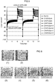
- the states of the CA membranes of each of the respective plural sensors are, as shown in Fig.6 , (1) no CA membrane (NoCA), (2) with CA membrane (YesCA), and (3) through (6) simulated defective membranes with 4% concentration CA membrane only covering a portion of the sensor section 4 (CA4%Spin-Ato -D).
- the dark portions at the lower part of the figure are the parts covered by the CA membrane.
- the defect ratio for each sensor is, respectively, (1) 100 percent, (2) 0 percent, (3) 65 percent, (4) 64 percent, (5) 35 percent, and (6) 10 percent.
- CA membrane examples concentrations of 2% (CA2%Spin), 3% (CA3%Spin) and 4% (CA4%Spin) are prepared. Due to the difficulties in actually measuring the membrane thickness of the CA membrane the membrane thickness of the CA membranes are indicated by concentrations of the membranes.
- the amount of change in the response current from immediately after application of the response voltage E2 (+400mV) for each of the sensors is illustrated in Fig. 7 .
- the sampling interval employed is 5 seconds.
- a graph illustrating the time until the absolute values of the amount of change in response current every 5 seconds ⁇ nA/mm 2 /5s becomes smaller than specific change amount threshold values (here, set at 0.2 nA/mm 2 ) are shown in Fig. 8 .
- the period of time until the change in response current becomes small is earlier for thinner membrane thickness sensors CA3%Spin and CA2%Spin than for the thickest sensor CA4%Spin.
- the cause of this difference in time is postulated to be due to response delay based on the glucose permeability restriction by the CA membrane.
- the time until the change of the response current becomes smaller is earlier in the sensors with simulated defective membranes CA4%Spin-A to -D than in the CA4%Spin sensor with completely covered surface.
- the change amount threshold value is 0.2 nA/mm 2 , however the change amount threshold values are appropriately set according to such factors as the specification of the sensor section 4 and the sampling periods.
- step 100 determination is made as to whether or not it is a timing for executing the processing of the testing mode. For example configuration may be determined such that the testing mode is executed every hour, or executed at predetermined times, and determination at this step is whether or not such a time has arrived. Configuration may also be made such that the execution timing of the testing mode is determined to be in the night time when there will be little influence on continuous monitoring. Configuration may also be made such that immediately after starting to use the continuous glucose monitoring device 1 the timing of testing mode execution is determined, for example so as to be executed on the seventh day from start of use, when no rapid change in the state of the sensor is anticipated. Processing transitions to step 102 when determined that the execution timing for the testing mode has arrived. However when determined that the execution timing for the testing mode has not yet arrived determination at step 100 is repeated until determined that the execution timing has arrived.
- step 102 the response voltage E2 is applied. For example a voltage of +400mV is applied for 120 seconds. Then, in step 104, at a specific sampling interval (for example 5 seconds), the amount of change of the response current ⁇ I is measured. Then at step 106, with the timing at which the response voltage E2 is applied at step 102 as a starting point, the time T until the measured amount of change of the response current ⁇ I becomes smaller than a specific change amount threshold value ⁇ Ith in the specific period of time when the response voltage E2 is applied is computed. Note that explanation is made of a case in which the amount of change of the response current ⁇ I is an absolute value. However, it is not limited to an absolute value, and the actual value may be employed.
- the time T until the amount of change of the response current ⁇ I becomes larger than a specific change amount threshold value ⁇ Ith is computed.
- the time T until the amount of change of the response current ⁇ I reaches a value in a specific range can be computed.
- time threshold value Tth is set with reference to the time when the response voltage E2 is applied until the amount of change of the response current ⁇ I becomes smaller than the change amount threshold value ⁇ Ith for a case when a sensor with normal semi-permeable membrane 45 is employed.
- the time threshold value Tth can be set at 70 ⁇ ⁇ seconds where ⁇ can be between 5 to 20 seconds.
- time T ⁇ time threshold value Tth determination is made that the state of the semi-permeable membrane 45 has changed, namely that a defect has occurred, and processing transitions to step 110. However, when time T ⁇ time threshold value Tth, determination is made that the state of the semi-permeable membrane 45 has not changed, that is, the semi-permeable membrane 45 is in a normal state, and the processing is ended.
- the defect ratio of the semi-permeable membrane 45 is derived based on the time T computed at step 106. Then, a correction value for the response current to be measured in the monitoring mode corrected according to the defect ratio is computed and stored in the storage unit 35.
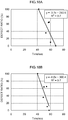
- the relationship between the time T and the defect ratio is plotted, as shown in Fig 10 .
- the times T in the case the change amount threshold value ⁇ Ith is set at 0.2 nA/mm 2 are computed, and the relationship between the times T and the defect ratios for each of the sensors are plotted on a graph with the horizontal axis as time T and the vertical axis as the defect ratio.
- the defect ratio may be taken as the proportion the membrane thickness (concentration) of the CA membrane of the sensor is smaller with respect to the membrane thickness (concentration) of the CA membrane of a normal sensor.
- a correspondence between the plotted time T and the defect ratio is derived and pre-stored in the storage unit 35.
- the correspondence of the time T to the defect ratio is then employed to derive the defect ratio corresponding to a time T computed at step 106. For example, in the example of Fig. 10 , if the time T is 60 seconds then the defect ratio is derived as 31.5%.
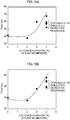
- Fig. 11A shows the relationship between the response current sensitivity obtained 100 seconds after applying the response voltage E2 with respect to the defect ratios of the CA membranes (1) through (6) shown in Fig. 6 .
- obtaining the response current sensitivity is not limited to this timing and the response current sensitivity can be obtained at any timing within the range in which there is a discernable amount of response current sensitivity.
- Fig. 11B the relationship between the defect ratio and a sensitivity normal-error difference of the sensor is plotted.
- the sensitivity normal-error difference is indicated as a proportion with normal response sensitivity taken as 100.
- the correspondence between the plotted defect ratio and the sensitivity normal-error difference is derived and pre-stored in the storage unit 35. Then the correspondence between the defect ratio and the sensitivity normal-error difference is employed to derive the sensitivity normal-error difference corresponding to the derived defect ratio. For example in the example of Fig. 11 , when the defect ratio is 31.5% a sensitivity normal-error difference of about 185.2% is derived. This sensitivity normal-error difference is then stored in the storage unit 35 and processing ended.
- the response current values actually measured are corrected, for example to a measured value/correction value using the above correction value, with this then output as the measurement result.
- the time employed to test the state of the semi-permeable membrane is the time until the amount of change of the response current immediately after a voltage that obtains a response caused by glucose is applied becomes less than a predetermined change amount threshold value.
- sensor state testing can be performed stably and in a short time without providing plural sets of working electrodes and counter electrodes.
- the execution time for the testing mode can be made shorter than in cases employing the time until the response current reaches a steady state. This is more efficient in cases such as the present exemplary embodiment in which continuous monitoring is performed.
- the second exemplary embodiment differs from the first exemplary embodiment in that the defect ratio of the sensor is determined based on the amount of change of the response current ⁇ I itself after the response voltage E2 is applied.
- the configuration of the continuous glucose monitoring device 1 of the second exemplary embodiment is the same as the continuous glucose monitoring device 1 of the first exemplary embodiment. Hence, the explanation thereof is omitted.
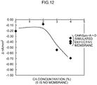
- the amount of change in the response current a predetermined period (here, 40 seconds) after application of the response voltage E2 (+400mV) using each of the sensors shown in Fig. 6 is illustrated in Fig. 12 .
- the change in response current is larger for thinner membrane thickness sensors CA3%Spin and CA2%Spin than for the thickest sensor CA4%Spin. The cause of this is postulated to be due to response delay based on the glucose permeability restriction by the CA membrane.
- the change of the response current is larger in the sensors with simulated defective membranes CA4%Spin-A to -D than in the CA4%Spin sensor with completely covered surface.
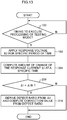
- step 100 determination is made as to whether or not it is a timing for executing the processing of the testing mode. Processing transitions to step 102 when determined that the execution timing for the testing mode has arrived. However, when determined that the execution timing for the testing mode has not yet arrived, determination at step 100 is repeated until determined that the execution timing has arrived.
- step 102 the response voltage E2 is applied for a specific length of time. For example a voltage of +400mV is applied for 40 seconds. Then at step 204, with the timing at which the response voltage E2 is applied in step 102 as a starting point, the amount of change of the response current ⁇ I is measured at a specific time thereafter.
- step 208 determination is made as to whether or not the amount of change of the response current ⁇ I measured in step 204 is larger than a specific change amount threshold value.
- ⁇ I > change amount threshold value ⁇ Ith the state of the semi-permeable membrane 45 is determined to have changed, namely that a defect has occurred, and processing transitions to step 210.
- ⁇ I ⁇ change amount threshold value ⁇ Ith the state of the semi-permeable membrane 45 is determined not to have changed, that is, the semi-permeable membrane 45 is in a normal state, and the processing is ended.
- the amount of change of the response current ⁇ I is an actual value. However, it is not limited to this, and an absolute value may be employed. In such a case, determination is made as to whether or not the the amount of change of the response current ⁇ I becomes smaller than a specific change amount threshold value ⁇ Ith.
- the defect ratio of the semi-permeable membrane 45 is derived based on the amount of change of the response current ⁇ I computed at step 204. Then, a correction value for the response current to be measured in the monitoring mode corrected according to the defect ratio is computed and stored in the storage unit 35.
- the relationship between the amount of change of the response current ⁇ I and the defect ratio is plotted, as shown in Fig 14 .
- the change amount threshold value ⁇ Ith is set at -0.2 nA/mm 2
- the relationship between the amount of change of the response current ⁇ I and the defect ratio for each sensor is plotted on a graph with the horizontal axis as representing the amount of change of the response current ⁇ I and the vertical axis as representing the defect ratio.
- a correspondence between the amount of change of the response current ⁇ I and the defect ratio is derived and pre-stored in the storage unit 35.
- the correspondence of the amount of change of the response current ⁇ I to the defect ratio is then employed to derive the defect ratio corresponding to the amount of change of the response current ⁇ I measured at step 204. Then, as in the first exemplary embodiment, the derived relationship between the defect ratio and the sensitivity normal-error difference is employed to derive the sensitivity normal-error difference corresponding to the derived defect ratio.
- the amount of change of the response current at a specific time after an immediate application of a voltage that obtains a response caused by glucose is used to test the state of the semi-permeable membrane.
- sensor state testing can be performed stably and in a short time without providing plural sets of working electrodes and counter electrodes.
- the execution time for the testing mode can be made shorter than in cases employing the time until the response current reaches a steady state. This is more efficient in cases such as the present exemplary embodiment in which continuous monitoring is performed.
- the exemplary embodiment differs from the first exemplary method not according to the invention in that the defect ratio of the sensor is determined based on both of the times T after the response voltage E2 and the non-response voltage E1 are applied.
- the configuration of the continuous glucose monitoring device 1 of the third exemplary embodiment is the same as the continuous glucose monitoring device 1 of the first exemplary embodiment. Hence, the explanation thereof is omitted.
- the response current is measured when a predetermined voltage pattern, such as illustrated in Fig. 5 , is applied.
- a predetermined voltage pattern such as illustrated in Fig. 5
- the state of the sensor section 4, and in particular the state of the semi-permeable membrane 45 is tested based on changes in response current when a voltage that obtains a response caused by glucose is applied, and on changes to the response current when a voltage that does not obtain a response caused by glucose is applied.
- Fig. 15A the amount of change in the response current from immediately after application of the response voltage E2 (+400mV) for each of the sensors shown in Fig. 6 is illustrated in Fig. 15A .
- Fig. 15A is the same as Fig. 7 .
- the sampling interval employed is 5 seconds.
- Graphs illustrating the time until the absolute values of the amount of change in response current every 5 seconds ⁇ nA/mm 2 /5s becomes smaller than specific change amount threshold values are shown in Fig. 16A and Fig. 16B.
- FIG. 16A illustrates when the response voltage E2 is applied
- Fig. 16B illustrates when the non-response voltage E1 is applied.
- Fig. 16A is the same as Fig. 8 .
- the change amount threshold value when the response voltage E2 is applied is set at 0.2 nA/mm 2
- the change amount threshold value when the non-response voltage E1 is applied is set at 0.5 nA/mm 2 .
- the period of time until the change in response current becomes small is earlier for thinner membrane thickness sensors CA3%Spin and CA2%Spin than for the thickest sensor CA4%Spin.
- the cause of this difference in time when the response voltage E2 is applied is postulated to be due to response delay based on the glucose permeability restriction by the CA membrane.
- the cause of this difference in time when the non-response voltage E1 is applied is postulated to be due to the difference in charge amount of the electric double layer on the electrode arising from the difference in states of the CA membrane.
- the time until the change of the response current becomes smaller is earlier in the sensors with simulated defective membranes CA4%Spin-A to -D than in the CA4%Spin sensor with completely covered surface.
- the change amount threshold value is 0.2 nA/mm 2 when the response voltage E2 is applied, and 0.5 nA/mm 2 when the non-response voltage E1 is applied, however the change amount threshold values are appropriately set according to such factors as the specification of the sensor section 4 and the sampling periods.
- step 300 determination is made as to whether or not it is a timing for executing the processing of the testing mode. Processing transitions to step 302 when determined that the execution timing for the testing mode has arrived. However when determined that the execution timing for the testing mode has not yet arrived determination at step 300 is repeated until determined that the execution timing has arrived.
- step 302 the non-response voltage E1 is applied for a specific period of time. For example a voltage of -200mV is applied for 240 seconds. Then, in step 304, at a specific sampling interval (for example 5 seconds), the amount of change of the response current ⁇ I E1 is measured. Then at step 306, with the timing when the non-response voltage E1 is applied at step 302 as a starting point, the time T E1 until the measured amount of change of the response current ⁇ I E1 becomes smaller than a specific change amount threshold value ⁇ Ith E1 is computed. Note that explanation is made of a case in which the amount of change of the response current ⁇ I E1 is an absolute value.
- the time T E1 until the amount of change of the response current ⁇ I E1 becomes larger than a specific change amount threshold value ⁇ Ith E1 is computed.
- the time T E1 until the amount of change of the response current ⁇ I E1 reaches a value within a specific range can be computed.
- the response voltage E2 is applied for a specific period of time. For example +400mV is applied for 120 seconds.
- a specific sampling interval for example every 5 seconds
- the amount of change of the response current ⁇ I E2 is measured.
- the time T E2 until the amount of change of the response current ⁇ I E2 becomes smaller than a specific change amount threshold value ⁇ Ith E2 is computed.
- step 314 comparison is made of the time T E1 computed at step 306 and a time threshold value Tth E1 , and of the time T E2 computed at step 312 and a time threshold value Tth E2 . Determination is then made as to whether or not both the time T E1 is smaller than the time threshold value Tth E1 and the time T E2 is smaller than the time threshold value Tth E2 .
- the time threshold value Tth E1 is set with reference to the time when the non-response voltage E1 is applied until the amount of change of the response current ⁇ I E1 becomes smaller than the change amount threshold value ⁇ Ith E1 for a case when a sensor with normal semi-permeable membrane 45 is employed.
- the time threshold value Tth E2 is set with reference to the time when the non-response voltage E2 is applied until the amount of change of the response current ⁇ I E2 becomes smaller than the change amount threshold value ⁇ Ith E2 for a case when a sensor with a normal semi-permeable membrane 45 is employed.
- the time threshold value Tth E2 can be set at 70 ⁇ ⁇ seconds.
- the time threshold value Tth E1 can be set at 58 ⁇ ⁇ seconds.
- ⁇ can be set between 5 to 20 seconds, for example.
- step 316 determination is made as to whether or not the time T E1 is smaller than the time threshold value Tth E1 but the time T E2 is equal to the time threshold value Tth E2 or greater, or the time T E1 is equal to the time threshold value Tth E1 or greater but the time T E2 is smaller than the time threshold value Tth E2 . Namely determination is made as to whether or not one or other of the times T is smaller than the respective time threshold values Tth. When negative determination is made, since both the times T are equal to the respective time threshold values Tth or greater, determination is made that the state of the semi-permeable membrane 45 has not changed, namely that it is normal, and processing is ended.
- step 318 determination is made as to whether or not the processing of step 314 or step 316 is already a re-test.
- processing returns to step 302 and the processing is repeated and a re-test performed.
- the state of the sensor is determined to be normal and processing ended.
- a defect ratio of the semi-permeable membrane 45 is derived based on the time T E2 computed at step 312, correction values for the response currents measured in the monitoring mode are computed according to the defect ratio, and stored in the storage section 35.
- the relationship between the time T E2 and the defect ratio is plotted, as shown in Fig 18A .
- the times T E2 in the case the change amount threshold value ⁇ Ith is set at 0.2 nA/mm 2 are computed, and the relationship between the times T E2 and the defect ratios for each of the sensors are plotted on a graph with the horizontal axis as representing time T E2 and the vertical axis as representing defect ratio.
- Fig. 18A is the same as Fig. 10 .
- a correspondence between the plotted time T E2 and the defect ratio is derived and pre-stored in the storage section 35.
- the correspondence of the time T E2 to the defect ratio is then employed to derive the defect ratio corresponding to a time T E2 computed at step 312.
- the defect ratio may be derived employing the time T E1 computed at step 306.
- configuration may be made such that both the defect ratio based on the time T E1 and the defect ratio based on the time T E2 are derived, and the average value, the larger value, or the smaller value of these defect ratios is then employed as the defect ratio.
- the derived relationship between the defect ratio and the sensitivity normal-error difference is employed to derive the sensitivity normal-error difference corresponding to the derived defect ratio.
- the times employed to test the state of the semi-permeable membrane 45 are both the time until the amount of change of the response current immediately after a voltage that obtains a response caused by glucose is applied becomes less than a predetermined threshold value, and the time until the amount of change of the response current immediately after a voltage that does not obtain a response caused by glucose is applied becomes less than a predetermined threshold value.
- the execution time for the testing mode can be made shorter than in cases employing the time until the response current reaches a steady state. This is more efficient in cases such as the present exemplary embodiment in which continuous monitoring is performed.
- the determination precision can be raised by determining whether or not a defect is present in a sensor using the change in response current to the non-response voltage E1. Furthermore, in cases in which at least the amount of change to the response current to the non-response voltage E1 is employed together with additionally employing the amount of change in the response current to the response voltage E2, determination is then made employing changes in response current to two different voltages, and determination precision can be further raised.
- the amount of change in the response current a predetermined period after application of the response voltage and the non-response voltage can also be employed.
- the amount of change in the response current a predetermined period (here, 40 seconds) after application of the non-response voltage E1 (-200mV) using each of the sensors shown in Fig. 6 is illustrated in Fig. 19 .
- the amount of change in the response current when the non-response voltage E1 is applied is the same as in Fig. 12 .
- the change in response current is smaller for thinner membrane thickness sensors CA3%Spin and CA2%Spin than for the thickest sensor CA4%Spin.
- the cause of this difference in time is postulated to be due to the difference in charge amount of the electric double layer on the electrode arising from the difference in states of the CA membrane.
- the change of the response current is smaller in the sensors with simulated defective membranes CA4%Spin-A to -D than in the CA4%Spin sensor with completely covered surface.
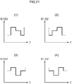
- Configuration may be made such that at a first step (a first step of a combination of a state in which the non-response voltage E1 is applied for a fixed period of time, and a state in which the response voltage E2 is applied for a fixed period of time) includes three constant voltages, as shown in Fig. 21 (1) to (4), however the number of constant voltages may be set at 2 or 4 or more.
- the testing frequency of the external layer membrane can accordingly be raised by the increase in the number of points at which electrical potential is changed.
- monitoring target composition to be tested is not limited to glucose.
- application is not limited a CGM device and application can also be made to a Self-Monitoring of Blood Glucose (SMBG) device.
- SMBG Blood Glucose
- configuration may be made such that testing is executed by the testing mode being selected by a user and a sample liquid being dripped on the sensor section by a user.
- configuration may be made such that a signal indicating that a defect in a sensor has occurred is output when a defect in a sensor is detected, and a correction value is either computed for output with this signal or not even computed.
- configuration may be made such that an output unit and an alarm unit are provided to the analyzing device, and when a defect in a sensor is detected a signal indicating that a defect in a sensor has occurred is output from the output unit to the alarm unit.
- a display, speaker or vibration unit may be provided as the alarm unit, such that a message that a defect in a sensor has occurred is displayed on the display, sound is output from the speaker, or the device is caused to vibrate when the alarm unit receives the signal from the output unit.
- Configuration may also be made such that the signal from an output unit is output for example to an external data processing apparatus and warning that a defect in a sensor has occurred is made by an alarm unit provided to the external data processing apparatus. Note that the configuration of the alarm unit is not limited to the examples referred to above.
- configuration may be made for example with a hard disk or with a ROM. Configuration may also be made with a CD-ROM, DVD disk, magneto-optical disk or IC card. Configuration may also be made such that the program is downloaded from a device such as a server connected to a network.
Landscapes
- Health & Medical Sciences (AREA)
- Life Sciences & Earth Sciences (AREA)
- Physics & Mathematics (AREA)
- Chemical & Material Sciences (AREA)
- Molecular Biology (AREA)
- Pathology (AREA)
- General Health & Medical Sciences (AREA)
- Hematology (AREA)
- Chemical Kinetics & Catalysis (AREA)
- Engineering & Computer Science (AREA)
- Optics & Photonics (AREA)
- Heart & Thoracic Surgery (AREA)
- Surgery (AREA)
- Animal Behavior & Ethology (AREA)
- Biomedical Technology (AREA)
- Public Health (AREA)
- Veterinary Medicine (AREA)
- Biophysics (AREA)
- Medical Informatics (AREA)
- Electrochemistry (AREA)
- Analytical Chemistry (AREA)
- Biochemistry (AREA)
- General Physics & Mathematics (AREA)
- Immunology (AREA)
- Emergency Medicine (AREA)
- General Chemical & Material Sciences (AREA)
- Measurement Of The Respiration, Hearing Ability, Form, And Blood Characteristics Of Living Organisms (AREA)
- Investigating Or Analysing Biological Materials (AREA)
Claims (15)
- Sensortestvorrichtung, die Folgendes umfasst:eine Spannungsanlegeeinheit, die konfiguriert ist zum Anlegen einer ersten Spannung zum Erhalten einer Antwort, die durch eine Substanz verursacht wird, und einer zweiten Spannung zum Erhalten entweder keiner Antwort oder im wesentlichen keiner Antwort, die durch die Substanz über einer ersten Elektrode (42A) und einer zweiten Elektrode (42B) eines Sensorabschnitts (4) verursacht wird, der mit einer Reagenzschicht (44) konfiguriert ist, die ein Reagenz (43) enthält, um mit der Substanz in einer Probenflüssigkeit zu reagieren, eine Elektrode (42), die die erste Elektrode (42A) und die zweite Elektrode (42B) umfasst, um eine Spannung an die Reagenzschicht (44) anzulegen, und eine Außenschichtmembran (45) zum Herstellen eines Kontakts mit der Reagenzschicht (44);eine Strommesseinheit, die dafür konfiguriert ist, den zwischen der ersten Elektrode (42A) und der zweiten Elektrode (42B) fließenden Strom kontinuierlich zu messen; und gekennzeichnet durch eine Bestimmungseinheit, die zum Bestimmen konfiguriert ist, ob ein Defekt in der Außenschichtmembran (45) vorhanden ist oder nicht, basierend auf Folgendem: einer ersten physikalischen Größe, die sich auf einen Änderungsbetrag pro spezifischer Zeitspanne eines ersten Stroms bezieht, der von der Strommesseinheit gemessen wird, wenn die erste Spannung angelegt wurde, und einer zweiten physikalischen Größe, die sich auf einen Änderungsbetrag pro spezifischer Zeitdauer eines zweiten Stroms bezieht, der von der Strommesseinheit gemessen wurde, wenn die zweite Spannung angelegt wurde.
- Analysevorrichtung (1), die Folgendes umfasst:eine Sensortestvorrichtung nach Anspruch 1; undeinen genannten Sensorabschnitt (4), der die genannte Reagenzschicht (44) umfasst, die das genannte Reagenz (43) umfasst, wobei die genannte Elektrode (42) die genannte erste Elektrode (42A) und die genannte zweite Elektrode (42B) und die genannte Außenschichtmembran (45) umfasst.
- Analysevorrichtung nach Anspruch 2, wobei die erste physikalische Größe eine erste Zeit ab dem Zeitpunkt ist, bis die Änderungsgröße pro bestimmter Zeitspanne des ersten Stroms einen Wert in einem vorbestimmten ersten bestimmten Bereich erreicht und die zweite physikalische Größe eine zweite Zeit ist, bis die Änderungsgröße pro bestimmter Zeitspanne des zweiten Stroms einen Wert in einem vorbestimmten zweiten bestimmten Bereich erreicht.
- Analysevorrichtung nach Anspruch 2 oder Anspruch 3, die ferner eine Korrektureinheit umfasst, die zum Korrigieren des von der Strommesseinheit gemessenen Stromwerts konfiguriert ist, wenn von der Bestimmungseinheit festgestellt wird, dass ein Defekt in der Außenschichtmembran (45) aufgetreten ist, wobei die Korrektureinheit dafür konfiguriert ist, eine Korrektur basierend auf einer vorbestimmten ersten Beziehung zwischen der ersten physikalischen Größe und einem Defektverhältnis der Außenschichtmembran (45) und/oder einer vorbestimmten zweiten Beziehung zwischen der zweiten physikalischen Größe und einem Defektverhältnis der Außenschichtmembran (45) durchzuführen.
- Analysevorrichtung nach Anspruch 4, wobei die Korrektureinheit für Folgendes konfiguriert ist: Schätzen des Fehlerverhältnisses basierend auf der ersten Beziehung und/oder der zweiten Beziehung, und Korrigieren des von der Strommesseinheit gemessenen Stromwerts, basierend auf einer vorbestimmten Beziehung zwischen dem Defektverhältnis der Außenschichtmembran (45) und dem vom Sensorabschnitt (4) gemessenen Stromwert, der mit einer Außenschichtmembran versehen ist, die Defekte aufweist, die dem Defektverhältnis entsprechen.
- Analysevorrichtung nach Anspruch 5, wobei, wenn die Korrektureinheit das Fehlerverhältnis basierend auf sowohl der ersten Beziehung als auch der zweiten Beziehung schätzt, die Korrektureinheit dafür konfiguriert ist, die Fehlerquote als Durchschnittswert, als Maximalwert oder als Minimalwert eines auf der Grundlage der ersten Beziehung geschätzten ersten Fehlerquotienten und eines auf der Grundlage der zweiten Beziehung geschätzten zweiten Fehlerquotienten zu berechnen.
- Analysevorrichtung nach einem der Ansprüche 2 bis 6, die ferner eine Ausgabeeinheit umfasst, die dafür konfiguriert ist, ein Signal auszugeben, das anzeigt, dass ein Defekt in dem Sensorabschnitt (4) aufgetreten ist, wenn durch die Bestimmungseinheit bestimmt wird, dass ein Defekt in der Außenschichtmembran (45) aufgetreten ist.
- Analysevorrichtung nach einem der Ansprüche 2 bis 7, wobei wenn sowohl die erste Spannung als auch die zweite Spannung angelegt werden, die Spannungsanlegeeinheit dafür konfiguriert ist, die erste Spannung und die zweite Spannung abwechselnd anzulegen.
- Analysevorrichtung nach einem der Ansprüche 2 bis 8, wobei die Strommesseinheit dafür konfiguriert ist, den zwischen der ersten Elektrode (42A) und der zweiten Elektrode (42B) fließenden Strom kontinuierlich zu messen, und die Bestimmungseinheit dafür konfiguriert ist, das Vorhandensein oder Fehlen eines Defekts in der Außenschichtmembran (45) zu einem vorbestimmten Zeitpunkt zu bestimmen.
- Analysevorrichtung nach einem der Ansprüche 2 bis 9, wobei während des Gebrauchs der Analysevorrichtung der Sensorabschnitt (4) unter der Haut eines Benutzers der Analysevorrichtung angeordnet ist und die Reagenzschicht (44) dafür ausgelegt ist, auf eine zu testende Zusammensetzung zu reagieren, die unter der Haut vorhanden ist.
- Analysevorrichtung nach einem der Ansprüche 2 bis 10, wobei die Reagensschicht (44) dafür ausgelegt ist, Elektronen aus der zu testenden Zusammensetzung zu extrahieren und die extrahierten Elektronen der Elektrode (42) zuzuführen.
- Analysevorrichtung nach einem der Ansprüche 2 bis 11, wobei die Reagensschicht (44) einen Enzymteil zum Extrahieren von Elektronen aus der zu testenden Zusammensetzung enthält.
- Sensortestverfahren, das Folgendes umfasst:Anlegen einer ersten Spannung, die eine durch eine Substanz verursachte Antwort erhält, und einer zweiten Spannung, die entweder keine Antwort oder im wesentlichen keine Antwort erhält, die durch die Substanz über einer ersten Elektrode (42A) und einer zweiten Elektrode (42B) eines Sensorabschnitts (4) verursacht wird, der mit einer Reagenzschicht (44) konfiguriert ist, die ein Reagenz (43) enthält, das mit der Substanz in einer Probenflüssigkeit reagiert, eine Elektrode (42), die die erste Elektrode (42A) und die zweite Elektrode (42B) umfasst, um eine Spannung an die Reagenzschicht (44) anzulegen, und eine Außenschichtmembran (45) zum Herstellen eines Kontakts mit der Reagenzschicht (44);kontinuierliches Messen des Stroms, der zwischen der ersten Elektrode (42A) und der zweiten Elektrode (42B) fließt; und dadurch gekennzeichnet, dass bestimmt wird, ob ein Defekt in der Außenschichtmembran (45) vorhanden ist oder nicht, basierend auf Folgendem: einer ersten physikalischen Größe, die sich auf einen Änderungsbetrag pro spezifischer Zeitspanne eines ersten gemessenen Stroms bezieht, wenn die erste Spannung angelegt wurde, und einer zweiten physikalischen Größe, die sich auf einen Änderungsbetrag pro spezifischer Zeitdauer eines zweiten gemessenen Stroms bezieht, wenn die zweite Spannung angelegt wurde.
- Sensortestprogramm, um die Vorrichtung nach Anspruch 1 zu veranlassen, das Verfahren nach Anspruch 13 auszuführen.
- Nichtflüchtiges computerlesbares Speichermedium, das das Programm nach Anspruch 14 speichert.
Applications Claiming Priority (3)
| Application Number | Priority Date | Filing Date | Title |
|---|---|---|---|
| JP2011021943 | 2011-02-03 | ||
| JP2011021942 | 2011-02-03 | ||
| JP2011286060A JP5819183B2 (ja) | 2011-02-03 | 2011-12-27 | 分析装置、センサの検査装置、検査方法、及び検査プログラム |
Publications (2)
| Publication Number | Publication Date |
|---|---|
| EP2485043A1 EP2485043A1 (de) | 2012-08-08 |
| EP2485043B1 true EP2485043B1 (de) | 2020-04-01 |
Family
ID=45655355
Family Applications (1)
| Application Number | Title | Priority Date | Filing Date |
|---|---|---|---|
| EP12153538.9A Active EP2485043B1 (de) | 2011-02-03 | 2012-02-01 | Vorrichtung und testverfahren zum testen von electrochemischen sensoren |
Country Status (4)
| Country | Link |
|---|---|
| US (3) | US9297777B2 (de) |
| EP (1) | EP2485043B1 (de) |
| JP (1) | JP5819183B2 (de) |
| CN (1) | CN102628832B (de) |
Families Citing this family (13)
| Publication number | Priority date | Publication date | Assignee | Title |
|---|---|---|---|---|
| DE102012202035B4 (de) * | 2012-02-10 | 2014-05-28 | Robert Bosch Gmbh | Mikromechanisches Bauelement mit einer Membran |
| EP2746759B1 (de) * | 2012-12-23 | 2016-09-07 | Tyson Bioresearch, Inc. | Verfahren zur Messung der Konzentration eines Analyts in einer Probe mittels eines Teststreifens |
| CN103048367B (zh) * | 2013-01-23 | 2015-01-21 | 黑龙江省计量检定测试院 | 家用血糖仪的检定装置的检定方法 |
| CA2902310C (en) * | 2013-03-14 | 2021-02-16 | Becton, Dickinson And Company | Continuous glucose monitoring on-body sensor having a visual display |
| JP2015020030A (ja) * | 2013-07-23 | 2015-02-02 | シャープ株式会社 | 生体音収集装置 |
| JP6209122B2 (ja) * | 2014-04-02 | 2017-10-04 | 株式会社日立ハイテクノロジーズ | 孔形成方法及び測定装置 |
| US9465683B2 (en) * | 2014-07-07 | 2016-10-11 | Infineon Technologies Ag | Apparatus and a method for providing an error signal for a control unit |
| EP3002582B1 (de) | 2014-10-03 | 2017-07-05 | ARKRAY, Inc. | Messvorrichtung, detektionsverfahren und messsystem |
| JP6220904B2 (ja) * | 2016-01-14 | 2017-10-25 | 本田技研工業株式会社 | 蓄電装置 |
| PL3216395T3 (pl) * | 2016-03-11 | 2021-12-27 | F. Hoffmann-La Roche Ag | Plaster do pomiaru analitu |
| CA3047218C (en) * | 2017-03-21 | 2023-08-29 | F. Hoffmann-La Roche Ag | Medical device and method for manufacturing a medical device useful for continuous monitoring of analytes and/or body functions |
| CN115877009A (zh) * | 2021-09-29 | 2023-03-31 | 苏州睿感医疗科技有限公司 | 持续血糖校正方法、装置和电子设备 |
| US12587995B2 (en) * | 2023-02-15 | 2026-03-24 | Qualcomm Incorporated | Map-aided node selection for positioning and radio frequency sensing |
Family Cites Families (15)
| Publication number | Priority date | Publication date | Assignee | Title |
|---|---|---|---|---|
| JPH0820412B2 (ja) | 1990-07-20 | 1996-03-04 | 松下電器産業株式会社 | 使い捨てセンサを用いた定量分析方法、及び装置 |
| US5593852A (en) | 1993-12-02 | 1997-01-14 | Heller; Adam | Subcutaneous glucose electrode |
| ZA938555B (en) | 1992-11-23 | 1994-08-02 | Lilly Co Eli | Technique to improve the performance of electrochemical sensors |
| US5846744A (en) | 1993-05-29 | 1998-12-08 | Cambridge Life Sciences Plc | Sensors based on polymer transformation |
| DE4445947C2 (de) * | 1994-12-22 | 1998-03-12 | Draegerwerk Ag | Verfahren zur Erkennung von Fehlerquellen bei amperometrischen Meßzellen |
| US6175752B1 (en) | 1998-04-30 | 2001-01-16 | Therasense, Inc. | Analyte monitoring device and methods of use |
| US6895263B2 (en) | 2000-02-23 | 2005-05-17 | Medtronic Minimed, Inc. | Real time self-adjusting calibration algorithm |
| AU784254B2 (en) | 2001-05-21 | 2006-03-02 | Bayer Corporation | Improved electrochemical sensor |
| US20030032874A1 (en) * | 2001-07-27 | 2003-02-13 | Dexcom, Inc. | Sensor head for use with implantable devices |
| WO2003044513A1 (en) * | 2001-11-20 | 2003-05-30 | Arkray, Inc. | Fail judging method and analyzer |
| JP2004233294A (ja) * | 2003-01-31 | 2004-08-19 | Tanita Corp | 電気化学センサ測定装置及びその測定方法 |
| US7132041B2 (en) | 2003-02-11 | 2006-11-07 | Bayer Healthcare Llc | Methods of determining the concentration of an analyte in a fluid test sample |
| US20040233294A1 (en) * | 2003-05-20 | 2004-11-25 | Mingjian Zheng | System and method for USB compatible I-frame only MPEG image compression |
| US8603768B2 (en) * | 2008-01-17 | 2013-12-10 | Lifescan, Inc. | System and method for measuring an analyte in a sample |
| EP2408368B1 (de) * | 2009-03-16 | 2020-04-29 | ARKRAY, Inc. | Verfahren zur durchgehenden messung der konzentration einer substanz |
-
2011
- 2011-12-27 JP JP2011286060A patent/JP5819183B2/ja active Active
-
2012
- 2012-02-01 EP EP12153538.9A patent/EP2485043B1/de active Active
- 2012-02-02 CN CN201210023388.8A patent/CN102628832B/zh active Active
- 2012-02-02 US US13/365,054 patent/US9297777B2/en active Active
-
2016
- 2016-02-18 US US15/046,478 patent/US20160161440A1/en not_active Abandoned
- 2016-02-18 US US15/046,477 patent/US10295495B2/en active Active
Non-Patent Citations (1)
| Title |
|---|
| None * |
Also Published As
| Publication number | Publication date |
|---|---|
| CN102628832A (zh) | 2012-08-08 |
| JP5819183B2 (ja) | 2015-11-18 |
| JP2012176229A (ja) | 2012-09-13 |
| EP2485043A1 (de) | 2012-08-08 |
| US9297777B2 (en) | 2016-03-29 |
| US20120199496A1 (en) | 2012-08-09 |
| CN102628832B (zh) | 2015-12-09 |
| US20160161440A1 (en) | 2016-06-09 |
| US10295495B2 (en) | 2019-05-21 |
| US20160161439A1 (en) | 2016-06-09 |
Similar Documents
| Publication | Publication Date | Title |
|---|---|---|
| US10295495B2 (en) | Analyzing device, sensor testing device, testing method and computer-readable storage medium | |
| US9588210B2 (en) | Analysis apparatus, analysis method and analysis system | |
| US10591459B2 (en) | Measuring apparatus and measuring method | |
| EP1394545A1 (de) | Methode zur Bestimmung einer Hämatokrit-korrigierten Glukosekonzentration in Vollblutproben, wobei die Hämatokritkonzentration durch Impedanzspektroskopie bestimmt wird | |
| CN108474758B (zh) | 用于改进血液中的尿素检测的混合离子载体离子选择性电极 | |
| WO2005103669A1 (ja) | 血液成分の測定方法、それに用いるバイオセンサおよび測定装置 | |
| US20070151868A1 (en) | Implantable electrode system, method and apparatus for measuring an analyte concentration in a human or animal body | |
| EP1455182A1 (de) | Ausfallbeurteilungsverfahren und analysierer | |
| JP6596169B2 (ja) | バイオセンサ中の干渉物質による寄与を検出する方法 | |
| RU2012146333A (ru) | Система и способ определения электрохимического аналита | |
| US11246512B2 (en) | Measuring apparatus, computer readable medium storing measuring program and measuring method | |
| US8974747B2 (en) | Bodily fluid analysis device | |
| US20170038331A1 (en) | System and method for compensating sample-related measurements based on polarization effects of test strips | |
| EP2871471B1 (de) | Messvorrichtung und Messverfahren | |
| JP2015520646A (ja) | 分析物の累積測定 | |
| US11959872B2 (en) | Method for measuring amount of blood component in blood | |
| US9562875B2 (en) | Measuring apparatus, detection method, electrochemical sensor and measuring system | |
| EP3667307B1 (de) | Verfahren zur messung der menge einer blutkomponente im blut | |
| JP6654383B2 (ja) | 測定装置、検知方法、電気化学センサ及び測定システム | |
| HK1241019B (zh) | 用於检测使用过且变乾的传感器的系统和方法 | |
| HK1206227A1 (en) | System and method for detecting used and dried sensors | |
| HK1241019A1 (en) | System and method for detecting used and dried sensors | |
| HK1206227B (en) | System and method for detecting used and dried sensors |
Legal Events
| Date | Code | Title | Description |
|---|---|---|---|
| PUAI | Public reference made under article 153(3) epc to a published international application that has entered the european phase |
Free format text: ORIGINAL CODE: 0009012 |
|
| AK | Designated contracting states |
Kind code of ref document: A1 Designated state(s): AL AT BE BG CH CY CZ DE DK EE ES FI FR GB GR HR HU IE IS IT LI LT LU LV MC MK MT NL NO PL PT RO RS SE SI SK SM TR |
|
| AX | Request for extension of the european patent |
Extension state: BA ME |
|
| 17P | Request for examination filed |
Effective date: 20130107 |
|
| RAP1 | Party data changed (applicant data changed or rights of an application transferred) |
Owner name: ARKRAY, INC. |
|
| STAA | Information on the status of an ep patent application or granted ep patent |
Free format text: STATUS: EXAMINATION IS IN PROGRESS |
|
| 17Q | First examination report despatched |
Effective date: 20180525 |
|
| GRAP | Despatch of communication of intention to grant a patent |
Free format text: ORIGINAL CODE: EPIDOSNIGR1 |
|
| STAA | Information on the status of an ep patent application or granted ep patent |
Free format text: STATUS: GRANT OF PATENT IS INTENDED |
|
| INTG | Intention to grant announced |
Effective date: 20190827 |
|
| GRAS | Grant fee paid |
Free format text: ORIGINAL CODE: EPIDOSNIGR3 |
|
| GRAA | (expected) grant |
Free format text: ORIGINAL CODE: 0009210 |
|
| STAA | Information on the status of an ep patent application or granted ep patent |
Free format text: STATUS: THE PATENT HAS BEEN GRANTED |
|
| AK | Designated contracting states |
Kind code of ref document: B1 Designated state(s): AL AT BE BG CH CY CZ DE DK EE ES FI FR GB GR HR HU IE IS IT LI LT LU LV MC MK MT NL NO PL PT RO RS SE SI SK SM TR |
|
| REG | Reference to a national code |
Ref country code: GB Ref legal event code: FG4D |
|
| REG | Reference to a national code |
Ref country code: AT Ref legal event code: REF Ref document number: 1252018 Country of ref document: AT Kind code of ref document: T Effective date: 20200415 Ref country code: CH Ref legal event code: EP |
|
| REG | Reference to a national code |
Ref country code: DE Ref legal event code: R096 Ref document number: 602012068852 Country of ref document: DE |
|
| REG | Reference to a national code |
Ref country code: IE Ref legal event code: FG4D |
|
| PG25 | Lapsed in a contracting state [announced via postgrant information from national office to epo] |
Ref country code: BG Free format text: LAPSE BECAUSE OF FAILURE TO SUBMIT A TRANSLATION OF THE DESCRIPTION OR TO PAY THE FEE WITHIN THE PRESCRIBED TIME-LIMIT Effective date: 20200701 |
|
| REG | Reference to a national code |
Ref country code: NL Ref legal event code: MP Effective date: 20200401 |
|
| REG | Reference to a national code |
Ref country code: LT Ref legal event code: MG4D |
|
| PG25 | Lapsed in a contracting state [announced via postgrant information from national office to epo] |
Ref country code: NL Free format text: LAPSE BECAUSE OF FAILURE TO SUBMIT A TRANSLATION OF THE DESCRIPTION OR TO PAY THE FEE WITHIN THE PRESCRIBED TIME-LIMIT Effective date: 20200401 Ref country code: CZ Free format text: LAPSE BECAUSE OF FAILURE TO SUBMIT A TRANSLATION OF THE DESCRIPTION OR TO PAY THE FEE WITHIN THE PRESCRIBED TIME-LIMIT Effective date: 20200401 Ref country code: GR Free format text: LAPSE BECAUSE OF FAILURE TO SUBMIT A TRANSLATION OF THE DESCRIPTION OR TO PAY THE FEE WITHIN THE PRESCRIBED TIME-LIMIT Effective date: 20200702 Ref country code: NO Free format text: LAPSE BECAUSE OF FAILURE TO SUBMIT A TRANSLATION OF THE DESCRIPTION OR TO PAY THE FEE WITHIN THE PRESCRIBED TIME-LIMIT Effective date: 20200701 Ref country code: SE Free format text: LAPSE BECAUSE OF FAILURE TO SUBMIT A TRANSLATION OF THE DESCRIPTION OR TO PAY THE FEE WITHIN THE PRESCRIBED TIME-LIMIT Effective date: 20200401 Ref country code: IS Free format text: LAPSE BECAUSE OF FAILURE TO SUBMIT A TRANSLATION OF THE DESCRIPTION OR TO PAY THE FEE WITHIN THE PRESCRIBED TIME-LIMIT Effective date: 20200801 Ref country code: LT Free format text: LAPSE BECAUSE OF FAILURE TO SUBMIT A TRANSLATION OF THE DESCRIPTION OR TO PAY THE FEE WITHIN THE PRESCRIBED TIME-LIMIT Effective date: 20200401 Ref country code: FI Free format text: LAPSE BECAUSE OF FAILURE TO SUBMIT A TRANSLATION OF THE DESCRIPTION OR TO PAY THE FEE WITHIN THE PRESCRIBED TIME-LIMIT Effective date: 20200401 Ref country code: PT Free format text: LAPSE BECAUSE OF FAILURE TO SUBMIT A TRANSLATION OF THE DESCRIPTION OR TO PAY THE FEE WITHIN THE PRESCRIBED TIME-LIMIT Effective date: 20200817 |
|
| REG | Reference to a national code |
Ref country code: AT Ref legal event code: MK05 Ref document number: 1252018 Country of ref document: AT Kind code of ref document: T Effective date: 20200401 |
|
| PG25 | Lapsed in a contracting state [announced via postgrant information from national office to epo] |
Ref country code: LV Free format text: LAPSE BECAUSE OF FAILURE TO SUBMIT A TRANSLATION OF THE DESCRIPTION OR TO PAY THE FEE WITHIN THE PRESCRIBED TIME-LIMIT Effective date: 20200401 Ref country code: RS Free format text: LAPSE BECAUSE OF FAILURE TO SUBMIT A TRANSLATION OF THE DESCRIPTION OR TO PAY THE FEE WITHIN THE PRESCRIBED TIME-LIMIT Effective date: 20200401 Ref country code: HR Free format text: LAPSE BECAUSE OF FAILURE TO SUBMIT A TRANSLATION OF THE DESCRIPTION OR TO PAY THE FEE WITHIN THE PRESCRIBED TIME-LIMIT Effective date: 20200401 |
|
| PG25 | Lapsed in a contracting state [announced via postgrant information from national office to epo] |
Ref country code: AL Free format text: LAPSE BECAUSE OF FAILURE TO SUBMIT A TRANSLATION OF THE DESCRIPTION OR TO PAY THE FEE WITHIN THE PRESCRIBED TIME-LIMIT Effective date: 20200401 |
|
| REG | Reference to a national code |
Ref country code: DE Ref legal event code: R097 Ref document number: 602012068852 Country of ref document: DE |
|
| PG25 | Lapsed in a contracting state [announced via postgrant information from national office to epo] |
Ref country code: AT Free format text: LAPSE BECAUSE OF FAILURE TO SUBMIT A TRANSLATION OF THE DESCRIPTION OR TO PAY THE FEE WITHIN THE PRESCRIBED TIME-LIMIT Effective date: 20200401 Ref country code: RO Free format text: LAPSE BECAUSE OF FAILURE TO SUBMIT A TRANSLATION OF THE DESCRIPTION OR TO PAY THE FEE WITHIN THE PRESCRIBED TIME-LIMIT Effective date: 20200401 Ref country code: DK Free format text: LAPSE BECAUSE OF FAILURE TO SUBMIT A TRANSLATION OF THE DESCRIPTION OR TO PAY THE FEE WITHIN THE PRESCRIBED TIME-LIMIT Effective date: 20200401 Ref country code: EE Free format text: LAPSE BECAUSE OF FAILURE TO SUBMIT A TRANSLATION OF THE DESCRIPTION OR TO PAY THE FEE WITHIN THE PRESCRIBED TIME-LIMIT Effective date: 20200401 Ref country code: SM Free format text: LAPSE BECAUSE OF FAILURE TO SUBMIT A TRANSLATION OF THE DESCRIPTION OR TO PAY THE FEE WITHIN THE PRESCRIBED TIME-LIMIT Effective date: 20200401 Ref country code: ES Free format text: LAPSE BECAUSE OF FAILURE TO SUBMIT A TRANSLATION OF THE DESCRIPTION OR TO PAY THE FEE WITHIN THE PRESCRIBED TIME-LIMIT Effective date: 20200401 |
|
| PLBE | No opposition filed within time limit |
Free format text: ORIGINAL CODE: 0009261 |
|
| STAA | Information on the status of an ep patent application or granted ep patent |
Free format text: STATUS: NO OPPOSITION FILED WITHIN TIME LIMIT |
|
| PG25 | Lapsed in a contracting state [announced via postgrant information from national office to epo] |
Ref country code: SK Free format text: LAPSE BECAUSE OF FAILURE TO SUBMIT A TRANSLATION OF THE DESCRIPTION OR TO PAY THE FEE WITHIN THE PRESCRIBED TIME-LIMIT Effective date: 20200401 Ref country code: PL Free format text: LAPSE BECAUSE OF FAILURE TO SUBMIT A TRANSLATION OF THE DESCRIPTION OR TO PAY THE FEE WITHIN THE PRESCRIBED TIME-LIMIT Effective date: 20200401 |
|
| 26N | No opposition filed |
Effective date: 20210112 |
|
| PG25 | Lapsed in a contracting state [announced via postgrant information from national office to epo] |
Ref country code: SI Free format text: LAPSE BECAUSE OF FAILURE TO SUBMIT A TRANSLATION OF THE DESCRIPTION OR TO PAY THE FEE WITHIN THE PRESCRIBED TIME-LIMIT Effective date: 20200401 |
|
| PG25 | Lapsed in a contracting state [announced via postgrant information from national office to epo] |
Ref country code: MC Free format text: LAPSE BECAUSE OF FAILURE TO SUBMIT A TRANSLATION OF THE DESCRIPTION OR TO PAY THE FEE WITHIN THE PRESCRIBED TIME-LIMIT Effective date: 20200401 |
|
| REG | Reference to a national code |
Ref country code: BE Ref legal event code: MM Effective date: 20210228 |
|
| PG25 | Lapsed in a contracting state [announced via postgrant information from national office to epo] |
Ref country code: LI Free format text: LAPSE BECAUSE OF NON-PAYMENT OF DUE FEES Effective date: 20210228 Ref country code: LU Free format text: LAPSE BECAUSE OF NON-PAYMENT OF DUE FEES Effective date: 20210201 Ref country code: CH Free format text: LAPSE BECAUSE OF NON-PAYMENT OF DUE FEES Effective date: 20210228 |
|
| PG25 | Lapsed in a contracting state [announced via postgrant information from national office to epo] |
Ref country code: IE Free format text: LAPSE BECAUSE OF NON-PAYMENT OF DUE FEES Effective date: 20210201 |
|
| PG25 | Lapsed in a contracting state [announced via postgrant information from national office to epo] |
Ref country code: BE Free format text: LAPSE BECAUSE OF NON-PAYMENT OF DUE FEES Effective date: 20210228 |
|
| PG25 | Lapsed in a contracting state [announced via postgrant information from national office to epo] |
Ref country code: HU Free format text: LAPSE BECAUSE OF FAILURE TO SUBMIT A TRANSLATION OF THE DESCRIPTION OR TO PAY THE FEE WITHIN THE PRESCRIBED TIME-LIMIT; INVALID AB INITIO Effective date: 20120201 Ref country code: CY Free format text: LAPSE BECAUSE OF FAILURE TO SUBMIT A TRANSLATION OF THE DESCRIPTION OR TO PAY THE FEE WITHIN THE PRESCRIBED TIME-LIMIT Effective date: 20200401 |
|
| PG25 | Lapsed in a contracting state [announced via postgrant information from national office to epo] |
Ref country code: MK Free format text: LAPSE BECAUSE OF FAILURE TO SUBMIT A TRANSLATION OF THE DESCRIPTION OR TO PAY THE FEE WITHIN THE PRESCRIBED TIME-LIMIT Effective date: 20200401 |
|
| PG25 | Lapsed in a contracting state [announced via postgrant information from national office to epo] |
Ref country code: MT Free format text: LAPSE BECAUSE OF FAILURE TO SUBMIT A TRANSLATION OF THE DESCRIPTION OR TO PAY THE FEE WITHIN THE PRESCRIBED TIME-LIMIT Effective date: 20200401 |
|
| PG25 | Lapsed in a contracting state [announced via postgrant information from national office to epo] |
Ref country code: TR Free format text: LAPSE BECAUSE OF FAILURE TO SUBMIT A TRANSLATION OF THE DESCRIPTION OR TO PAY THE FEE WITHIN THE PRESCRIBED TIME-LIMIT Effective date: 20200401 |
|
| PGFP | Annual fee paid to national office [announced via postgrant information from national office to epo] |
Ref country code: GB Payment date: 20260219 Year of fee payment: 15 |
|
| PGFP | Annual fee paid to national office [announced via postgrant information from national office to epo] |
Ref country code: DE Payment date: 20260218 Year of fee payment: 15 |
|
| PGFP | Annual fee paid to national office [announced via postgrant information from national office to epo] |
Ref country code: IT Payment date: 20260224 Year of fee payment: 15 |
|
| PGFP | Annual fee paid to national office [announced via postgrant information from national office to epo] |
Ref country code: FR Payment date: 20260218 Year of fee payment: 15 |