EP2484914A2 - Impeller and fluid pump - Google Patents
Impeller and fluid pump Download PDFInfo
- Publication number
- EP2484914A2 EP2484914A2 EP12153683A EP12153683A EP2484914A2 EP 2484914 A2 EP2484914 A2 EP 2484914A2 EP 12153683 A EP12153683 A EP 12153683A EP 12153683 A EP12153683 A EP 12153683A EP 2484914 A2 EP2484914 A2 EP 2484914A2
- Authority
- EP
- European Patent Office
- Prior art keywords
- vane
- impeller
- face
- cap
- rotation
- Prior art date
- Legal status (The legal status is an assumption and is not a legal conclusion. Google has not performed a legal analysis and makes no representation as to the accuracy of the status listed.)
- Granted
Links
Images


Classifications
-
- F—MECHANICAL ENGINEERING; LIGHTING; HEATING; WEAPONS; BLASTING
- F04—POSITIVE - DISPLACEMENT MACHINES FOR LIQUIDS; PUMPS FOR LIQUIDS OR ELASTIC FLUIDS
- F04D—NON-POSITIVE-DISPLACEMENT PUMPS
- F04D29/00—Details, component parts, or accessories
- F04D29/18—Rotors
- F04D29/188—Rotors specially for regenerative pumps
-
- F—MECHANICAL ENGINEERING; LIGHTING; HEATING; WEAPONS; BLASTING
- F04—POSITIVE - DISPLACEMENT MACHINES FOR LIQUIDS; PUMPS FOR LIQUIDS OR ELASTIC FLUIDS
- F04D—NON-POSITIVE-DISPLACEMENT PUMPS
- F04D5/00—Pumps with circumferential or transverse flow
-
- F—MECHANICAL ENGINEERING; LIGHTING; HEATING; WEAPONS; BLASTING
- F02—COMBUSTION ENGINES; HOT-GAS OR COMBUSTION-PRODUCT ENGINE PLANTS
- F02M—SUPPLYING COMBUSTION ENGINES IN GENERAL WITH COMBUSTIBLE MIXTURES OR CONSTITUENTS THEREOF
- F02M37/00—Apparatus or systems for feeding liquid fuel from storage containers to carburettors or fuel-injection apparatus; Arrangements for purifying liquid fuel specially adapted for, or arranged on, internal-combustion engines
- F02M37/04—Feeding by means of driven pumps
- F02M37/08—Feeding by means of driven pumps electrically driven
-
- F—MECHANICAL ENGINEERING; LIGHTING; HEATING; WEAPONS; BLASTING
- F04—POSITIVE - DISPLACEMENT MACHINES FOR LIQUIDS; PUMPS FOR LIQUIDS OR ELASTIC FLUIDS
- F04D—NON-POSITIVE-DISPLACEMENT PUMPS
- F04D13/00—Pumping installations or systems
- F04D13/02—Units comprising pumps and their driving means
- F04D13/06—Units comprising pumps and their driving means the pump being electrically driven
-
- F—MECHANICAL ENGINEERING; LIGHTING; HEATING; WEAPONS; BLASTING
- F04—POSITIVE - DISPLACEMENT MACHINES FOR LIQUIDS; PUMPS FOR LIQUIDS OR ELASTIC FLUIDS
- F04D—NON-POSITIVE-DISPLACEMENT PUMPS
- F04D29/00—Details, component parts, or accessories
- F04D29/26—Rotors specially for elastic fluids
- F04D29/28—Rotors specially for elastic fluids for centrifugal or helico-centrifugal pumps for radial-flow or helico-centrifugal pumps
- F04D29/30—Vanes
-
- F—MECHANICAL ENGINEERING; LIGHTING; HEATING; WEAPONS; BLASTING
- F04—POSITIVE - DISPLACEMENT MACHINES FOR LIQUIDS; PUMPS FOR LIQUIDS OR ELASTIC FLUIDS
- F04D—NON-POSITIVE-DISPLACEMENT PUMPS
- F04D29/00—Details, component parts, or accessories
- F04D29/40—Casings; Connections of working fluid
- F04D29/42—Casings; Connections of working fluid for radial or helico-centrifugal pumps
- F04D29/426—Casings; Connections of working fluid for radial or helico-centrifugal pumps especially adapted for liquid pumps
- F04D29/4273—Casings; Connections of working fluid for radial or helico-centrifugal pumps especially adapted for liquid pumps suction eyes
-
- F—MECHANICAL ENGINEERING; LIGHTING; HEATING; WEAPONS; BLASTING
- F04—POSITIVE - DISPLACEMENT MACHINES FOR LIQUIDS; PUMPS FOR LIQUIDS OR ELASTIC FLUIDS
- F04D—NON-POSITIVE-DISPLACEMENT PUMPS
- F04D29/00—Details, component parts, or accessories
- F04D29/40—Casings; Connections of working fluid
- F04D29/42—Casings; Connections of working fluid for radial or helico-centrifugal pumps
- F04D29/426—Casings; Connections of working fluid for radial or helico-centrifugal pumps especially adapted for liquid pumps
- F04D29/4293—Details of fluid inlet or outlet
-
- F—MECHANICAL ENGINEERING; LIGHTING; HEATING; WEAPONS; BLASTING
- F04—POSITIVE - DISPLACEMENT MACHINES FOR LIQUIDS; PUMPS FOR LIQUIDS OR ELASTIC FLUIDS
- F04D—NON-POSITIVE-DISPLACEMENT PUMPS
- F04D5/00—Pumps with circumferential or transverse flow
- F04D5/002—Regenerative pumps
- F04D5/003—Regenerative pumps of multistage type
- F04D5/005—Regenerative pumps of multistage type the stages being radially offset
-
- F—MECHANICAL ENGINEERING; LIGHTING; HEATING; WEAPONS; BLASTING
- F04—POSITIVE - DISPLACEMENT MACHINES FOR LIQUIDS; PUMPS FOR LIQUIDS OR ELASTIC FLUIDS
- F04D—NON-POSITIVE-DISPLACEMENT PUMPS
- F04D5/00—Pumps with circumferential or transverse flow
- F04D5/002—Regenerative pumps
- F04D5/007—Details of the inlet or outlet
-
- Y—GENERAL TAGGING OF NEW TECHNOLOGICAL DEVELOPMENTS; GENERAL TAGGING OF CROSS-SECTIONAL TECHNOLOGIES SPANNING OVER SEVERAL SECTIONS OF THE IPC; TECHNICAL SUBJECTS COVERED BY FORMER USPC CROSS-REFERENCE ART COLLECTIONS [XRACs] AND DIGESTS
- Y10—TECHNICAL SUBJECTS COVERED BY FORMER USPC
- Y10T—TECHNICAL SUBJECTS COVERED BY FORMER US CLASSIFICATION
- Y10T29/00—Metal working
- Y10T29/49—Method of mechanical manufacture
- Y10T29/49316—Impeller making
Definitions
- the present disclosure relates generally to fuel pumps and more particularly to a turbine type fuel pump.
- Electric motor driven pumps may be used to pump various liquids.
- electric motor driven pumps are used to pump fuel from a fuel tank to a combustion engine.
- turbine type fuel pumps having an impeller with a plurality of vanes may be used.
- a fluid pump may include an electric motor having an output shaft driven for rotation about an axis and a pump assembly coupled to the output shaft of the motor.
- the pump assembly has a first cap and a second cap with at least one pumping channel defined between the first cap and the second cap, and an impeller received between the first cap and the second cap.
- the impeller is driven for rotation by the output shaft of the motor and includes a plurality of vanes in communication with the at least one pumping channel.
- Each vane has a root segment and a tip segment and a line from a base of the root segment to an outer edge of the tip segment trails a line extending from the axis of rotation to the base of the root segment by an angle of between 0° and 30° relative to the direction of rotation of the impeller.
- An impeller for a fluid pump includes a hub having an opening adapted to receive a shaft that drives the impeller for rotation, a mid-hoop spaced radially from the hub and an outer hoop spaced radially from the mid-hoop, and inner and outer arrays of vanes.
- the inner array of vanes is located radially outwardly of the hub and inwardly of the mid-hoop.
- the outer array of vanes is located radially outwardly of the mid-hoop.
- Each vane in the inner array and the outer array has a leading face and a trailing face spaced circumferentially behind the leading face relative to the intended direction of rotation of the impeller.
- Each vane has a root segment and a tip segment extending generally radially outwardly from the root segment, and each vane is oriented so that a line from a base of the root segment to an outer edge of the tip segment trails a line extending from the axis of rotation to the base of the root segment by an angle of between 0° and 30°, relative to the direction of rotation of the impeller.
- a method of making an impeller includes forming an impeller having a plurality of vanes and adapted to be rotated about an axis, forming a body that defines a radially outer sidewall of an impeller cavity in which the impeller rotates, and machining an axial face of the impeller and the body while the impeller is disposed radially inwardly of the sidewall to provide a similar axial thickness of both the sidewall and impeller.
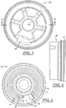
- FIG. 1 is a sectional view of an exemplary fluid pump showing portions of an electric motor and pumping assembly of the fluid pump;
- FIG. 2 is a sectional view of a pumping assembly of the fluid pump showing upper and lower caps and an impeller;
- FIG. 3 is a top view of the upper cap
- FIG. 4 is a side view of the upper cap
- FIG. 5 is a sectional view of the upper cap
- FIG. 6 is a bottom view of the upper cap showing a lower surface of the upper cap
- FIG. 7 is a top view of the lower cap showing an upper surface of the lower cap
- FIG. 8 is a side view of the lower cap
- FIG. 9 is a sectional view of the lower cap
- FIG. 10 is a fragmentary sectional view of a portion of the lower cap showing vent passages formed therein;
- FIG. 11 is a perspective view of the impeller
- FIG. 12 is a top view of the impeller
- FIG. 13 is a sectional view of the impeller taken along line 13-13 in FIG. 12 ;
- FIG. 14 is an enlarged, fragmentary sectional view taken along line 14-14 in FIG. 12 ;
- FIG. 15 is an enlarged, fragmentary sectional view taken along line 15-15 in FIG. 12 ;
- FIG. 16 is an enlarged, fragmentary view of a portion of the impeller
- FIG. 17 is an enlarged, fragmentary sectional view of a modified impeller
- FIG. 18 is an enlarged fragmentary sectional view of the impeller assembled in the upper and lower caps.
- FIG. 19 is a fragmentary sectional view of an alternate fuel pump including a ring radially surrounding at least a portion of the impeller.
- FIG. 1 illustrates a liquid pump 10 that has a turbine type or impeller pump assembly 12 that may be driven for rotation by an electric motor 14.
- the pump 10 can used to pump any suitable liquid including, and for purposes of the rest of this description, automotive fuels.
- the pump 10 may be utilized in an automotive fuel system to supply fuel under pressure to the vehicle's engine.
- the fuel may be of any suitable type, and the pump 10 may be adapted for use in a so-called "flex fuel vehicle” that may use standard gasoline as well as alternative fuels like ethanol based E85 fuel.
- the motor 14 and associated components may be of conventional construction and may be enclosed, at least in part, by an outer housing or sleeve 16.
- the pump assembly 12 may also be enclosed, at least in part, by the sleeve 16 with an output shaft 18 of the motor 14 received within a central opening 20 of an impeller 22 to rotatably drive the impeller 22 about an axis 24 of rotation.
- the pump assembly 12 may include a first or lower cap 28 and a second or upper cap 26 held together and generally encircled by the sleeve 16.
- An impeller cavity 30 in which the impeller 22 is received may be defined between a lower surface 32 of an upper cap 26 and an upper surface 34 of a lower cap 28.
- the lower surface 32 and upper surface 34 may be generally flat or planar, and may extend perpendicularly to the axis 24 of rotation.
- the motor output shaft 18 may extend through a central passage 36 in the upper cap 26, be coupled to and project through the opening 20 in the impeller 22 with an end of the shaft 18 supported by a bearing 38 located in a blind bore 40 in the lower cap 28.
- One or more fuel pumping channels 46, 48 are defined within the impeller cavity 30.
- the pumping channels 46, 48 may be defined by and between the impeller 22 and the upper and lower caps 26, 28.
- the pumping channels 46, 48 may communicate with and extend between an inlet passage 42 and an outlet passage 44, so that fuel enters the pumping channels 46, 48 from the inlet passage 42 and fuel is discharged from the pumping channels 46, 48 through the outlet passage 44.
- two pumping channels are provided, with an inner pumping channel 46 disposed radially inwardly or an outer pumping channel 48.
- the lower cap 28 FIGS.
- 1, 2 , 7-9 may define all or part of the inlet passage 42 through which fuel flows from a fluid reservoir or fuel tank (not shown) into the pumping channels 46, 48.
- the upper cap 26 FIGS. 1-6 ) may define all or part of an outlet passage 44 through which pressurized fuel is discharged from the pumping channels 46, 48.
- the inner pumping channel 46 may be defined in part by opposed grooves, with one groove 50 ( FIGS. 5 and 6 ) formed in the lower surface 32 of the upper cap 26 and the other groove 52 ( FIGS. 7 and 9 ) formed in the upper surface 34 of the lower cap 28.
- the outer pumping channel 48 may also be defined in part by opposed grooves, with one groove 54 ( FIGS. 5 and 6 ) formed in the lower surface 32 of the upper cap 26 and the other groove 56 ( FIGS. 7 and 9 ) formed in an upper surface 34 of the lower cap 28.
- the grooves 50-56 may all be symmetrically shaped and sized, or, they could be non-symmetrically shaped and/or sized.
- vent paths 59 may be provided for one or both pumping channels 46, 48 to hermit vapor to escape or be expelled from the channels.
- the inlet passage 42 may lead to an entrance portion 58 of the pumping channels 46, 48, with the entrance portion of outer pumping channel 48 shown.
- the depth of the pumping channel 48 may change from a greater depth adjacent to the inlet passage 42 to a lesser depth downstream thereof.
- the reduction in flow area downstream of the inlet passage 42 facilitates increasing the pressure and velocity of the fuel as it flows through this region of the pump assembly 12.
- the entrance portion may be disposed at an angle ⁇ ( FIG. 2 ) of between about 0° and 30°. In one presently preferred application, angle ⁇ is between about 13° and 14°.
- the outer pumping channel 48 may have a cross-sectional area that is larger than that of the inner pumping channel 46.
- the inner pumping channel 46 may operate at a lower tangential velocity and a higher pressure coefficient than the outer pumping channel 48 (due to the smaller radius and the shorter circumferential length of the inner pumping channel).
- a smaller cross-sectional area may be used for the inner pumping channel 46 compared to the outer pumping channel 48.
- the pumping channels 46, 48 may extend circumferentially or for an angular extent of less than 360°, and in certain applications, about 300-350° about the axis of rotation. This provides a circumferential portion of the upper and lower caps 26, 28 without any grooves, and where there is limited axial clearance between the upper surface 34 of the lower cap 28 and the impeller lower face 60, and the lower surface 32 of the upper cap 26 and upper face 62 of the impeller 22.
- This circumferential portion without grooves may be called a stripper portion or partition 65 and is intended to isolate the lower pressure inlet end of the pumping channels 46, 48 from the higher pressure outlet end of the pumping channels.
- a radially inward edge of the inlet 42 at the face 34 of the lower body 28 may be radially aligned with a radially inward edge of the inlet at the face 32 of the upper body 26 (shown at point Y). That is, a line connecting point X and point Y may be parallel to the axis of rotation.
- the radially inward edge of the outlet 44 at the face 34 of the lower body 28 may be circumferentially offset from the radially inward edge of the outlet 44 at the face 32 of the upper body 26 (shown at point Z) by between about 0° and 20°, with a presently preferred offset in one application being about 4°.
- points X and Y may be circumferentially offset from point Z by about 10° to 25°, with a presently preferred offset in one application being about 23°. These angles may be measured between lines that are parallel to the axis of rotation and extend through the noted points.
- the pumping channels 46, 48 may also be defined in part by the impeller 22.
- impeller 22 may be a generally disc-shaped component having a generally planar upper face 62 received adjacent to the lower surface 32 of the upper cap 26, and a generally planar lower face 60 received adjacent to the upper surface 34 of the lower cap 28.
- the impeller 22 may include a plurality of vanes 64a,b each radially spaced from the axis of rotation 24 and aligned within a pumping channel 46 or 48.
- the impeller includes an inner array 66 of vanes 64a that are rotated through the inner pumping channel 46 and an outer array 68 of vanes 64b that are rotated through the outer pumping channel 48.
- a circular hub 70 of the impeller 22 may be provided radially inwardly of the inner array 66 of vanes and a key hole or non-circular hole 20 may be provided to receive the motor output shaft 18 such that the shaft and impeller co-rotate about axis 24.
- a mid-hoop 72 may be defined radially between the inner and outer vane arrays 66, 68, and an outer hoop 74 may be provided or formed radially outward of the outer vane array 68.
- the upper face 62 and lower face 60 of the impeller 22 may be arranged in close proximity to, and perhaps in a fluid sealing relationship with, the lower surface 32 of the upper cap 26 and the upper surface 34 of the lower cap 28, respectively.
- Vane pockets 76a,b may be formed between each pair of adjacent vanes 64a,b on the impeller 22, and between the mid-hoop 72 and outer hoop 74.
- the vane pockets 76a,b of both the inner and outer vane arrays 66, 68 are open on both their upper and lower axial faces, such that the vane pockets 76a,b are in fluid communication with the upper and lower grooves 50-56.
- Inner and outer vane arrays 66, 68 respectively propel the fuel through circumferentially extending inner and outer pumping channels 46, 48 as the impeller 22 is driven for rotation.
- the inner vane array 66 includes numerous vanes 64a that each project generally radially outwardly from the inner hub 70 to the mid-hoop 72.
- the outer vane array 68 includes numerous vanes 64b that each project generally radially outwardly from the mid-hoop 72 to the outer hoop 74.
- the mid-hoop 72 separates the inner vane array 66 from the outer vane array 68.
- the varies 64a,b of both the inner and outer vane arrays 66, 68 and the mid-hoop 72 and outer hoop 74 may extend axially the same distance, generally denoted by dimension "a" on FIGS. 14 and 15 .
- Each vane 64a,b may have a desired circumferential thickness denoted by dimension "b" on FIGS. 14 and 15 .
- the shape, orientation and spacing between the vanes 64a of the inner vane array 66 may be different than for the vanes 64b of the outer vane array 68, or the arrangement of the vanes 64a, 64b in both vane arrays may be the same.
- the shape and orientation of the vanes 64a,b is the same in the inner and outer vane arrays 66, 68, although the inner array 66 is smaller radially and circumferentially than the outer array 68 and preferably has fewer vanes than the outer array.
- FIG. 16 there is shown an enlarged view of part of the inner and outer vane arrays 66, 68.
- the following description is directed primarily to the outer vane array 68 but applies also to the inner vane array 66, unless otherwise stated.
- the impeller 22 is rotated counterclockwise, as viewed in FIG. 16 and as indicated by arrow 80, by tine motor to take fuel in through the inlet 42 and discharge fuel under pressure through the outlet 44.
- Each vane 64b has a leading face 82 and a trailing face 84 that is disposed circumferentially behind the leading face, relative to the direction of rotation.
- each vane 64b may be generally v-shaped in cross-section with ends adjacent to each axial face 60, 62 of the impeller 22 leading (i.e. inclined forwardly relative to the direction of rotation) an axial mid-point 86 of the vane.
- FIG. 14 shows a similar view of some vanes 64a from the inner vane array 66.
- the vanes 64a,b may be defined as having an upper half that extends axially from the upper face 62 of the impeller 22 to the mid-point 86 and a lower half that extends axially from the mid-point 86 to the lower face 60 of the impeller 22.
- the axial midpoint 86 of each vane 64b trails the portion of each vane adjacent the upper face 62 of the impeller 22.
- the axial mid-point 86 of each vane 64b trails the portion of the vane adjacent the lower face 60 of the impeller 22.
- This provides a generally concave vane in the cross-section views of FIGS. 14 and 15 .
- the front face of both the upper and lower halves of the vanes 64a,b is also concave, and the rear face of each half is convex.
- the upper and lower halves of the vanes 64b converge at the mid-point 86 and may define a relatively sharp transition and the v-shape as discussed above.
- the angle ⁇ defined between the upper and lower halves in each vane may be between 60° and 130°.
- a modified impeller 22' is shown in FIG. 17 wherein the leading face 82' of each vane 64b' has an arcuate or radiused region 88 in the area the axial mid-point 86' of each vane, providing more of a U-shape in that area rather than a sharp V-shape.
- the radius may be 90% less than to 50% greater than the minimum spacing in any direction (nominally denoted by dimension "c", which could be at other positions and angles in other designs) between (1) the leading face 82' of a vane and (2) the trailing face 84' of the adjacent vane, along the axial length of the vanes. So, by way of a non-limiting example, if the minimum length or distance of the vane pocket 76b' is 1mm, then the radius would be between 0.1 mm and 1.5mm.
- an angle ⁇ is formed between the entrance portion 58 of a pumping channel 46 or 48 and the lower half of an associated vane 64a or 64b.
- the angle ⁇ is greater than 109° for both pumping channels 46 and 48 and associated vanes 64a and 64b.
- the angle ⁇ for the inner pumping channel 46 and inner vanes 64a is between 110° and 120°, aild may be about 114°.
- the angle ⁇ for the outer pumping channel 48 and outer vanes 64b is between 110° and 125°, and may be about 121-122°.
- each vane 64b includes a root segment 90 that extends outwardly from the mid-hoop 72 (the root segment 90 of the vanes 64a in the inner array 66 extend outwardly from the hub 70 rather than the mid-hoop 72).
- the root segment 90 may be linear, or nearly so, if desired, and may be between about 10% to 50% of the radial length of the vane 64b.
- the root segment 90 may extend at an angle ⁇ to a radial line 92 extending from the axis of rotation 24 through a point A on the trailing face 84 of the vane at the radially inward end of the root segment 90.
- the angle ⁇ may be between about -20° to 10° and is shown between the radial line 92 and a line 93 extending along the root segment 90 on the trailing face 84 of the vane 64b.
- An angle less than zero indicates that the root segment 90 (and hence, line 93) is inclined rearwardly compared to the radial line 92 and relative to the direction of rotation 80.
- An angle greater than zero indicates that the root segment 90 is inclined forwardly compared to the radial line 92 and relative to the direction of rotation.
- ⁇ is about - 3° which means the root segment 90 is retarded or angled rearwardly of the radial line 92.
- Each vane 64b also includes a tip segment 96 that extends from the radially outer end of the root segment 90 to the outer hoop 74 (the tip segment 96 of the vanes 64a in the inner array 66 extend to the mid-hoop 72 rather than the outer hoop 74).
- tip segment 96 is slightly curved such that it is convex (when viewed in a direction parallel to the axis of rotation 24) with respect to the direction of rotation 80.
- the radially outermost portion of the tip segment 96 trails the root segment 90 relative to the direction of rotation 80.
- An angle ⁇ is formed between the radial line 92 and a line 98 extending from a point A at the mid-hoop 72 on the trailing face 84 of the vane (i.e. the base of the root segment 90) to a point C at the outer hoop 74 on the trailing face 84 of the vane (i.e. the end of the tip segment 96).
- the angle ⁇ may be between about 0° and -30°, where zero degrees coincides with the radial line 92 and angles of less than zero degrees indicate that the line 98 trails the radial line 92 relative to the direction of rotation 80.
- angle ⁇ is about -12° which means the vane 64b is retarded or angled rearwardly of the radial line 92.
- the orientation of the vane 64b may also be described with referent to a line 100 that extends from point D at the radial mid-point 86 of the vane 64b to point C.
- Line 100 may form an angle ⁇ with the radial line 92, and this angle ⁇ may range between about 5° and 45°.
- tip segment 96 may have a generally uniform curvature that may be defined by an imaginary radius in the range of between 2mm to 30mm.
- no portion of the vane 64b extends forwardly of or leads the radial line 92, relative to the direction of rotation of the impeller.
- the tip segment 96 of the vane may extend more rearwardly of the radial line 92 than the root segment 90.
- a rib or partition 100 extends circumferentially between adjacent vanes with a tip 102 axially centered between the faces 60, 62 of the impeller.
- the rib 100 may extend radially outwardly, and may extend between about 1 ⁇ 4 and 1 ⁇ 2 of the radial extent of its associated vanes.
- each groove in cross-section has a straight section 104, a first curved section 106, a bottom straight section 108, a second curved section 110, and a straight section 112.
- Each straight section 104, 112 may be perpendicular to the adjacent face of the impeller 22 and the straight section 108 may be parallel to an adjacent face of the impeller.
- the curved sections 106 and 110 may have radii of the same length with different centers and blend smoothly into the adjoining straight sections at both ends of each curved section.
- each inner vane 64a to the axial extent F of its pumping channel 46 may (but is not required to) have the relationship of F/E ⁇ 0.6.
- the axial extent G of each outer vane 64b to the axial extent H of its pumping channel 48 may have the relationship of H/G > 0.76.
- the ratio of the area A 2 of a pump channel 46 or 48 including the area of an associated vane 64a or 64b to the area A 1 of its associated vane 64a or 64b excluding the area of its rib 100 is A 2 /A 1 ⁇ 1.0.
- for the inner channel 46 and inner vanes 64a A 2 /A 1 ⁇ 0.7
- for the outer channel 48 and outer vanes 64b A 2 /A 1 ⁇ 0.9.
- rotation of impeller 22 causes fuel to flow into the pump assembly 12 via the fuel inlet passage 42, which communicates with the inner and outer pumping channels 46, 48.
- the rotating impeller 22 moves fuel from the inlet 42 toward the outlet 44 of the fuel pumping channels and increases the pressure of the fuel along the way. Once the fuel reaches the annular end of the pumping channels 46, 48, the now pressurized fuel exits pump assembly 12 through the fuel outlet passage 44.
- orienting the root segment 90 at a different angle than the tip segment 96, and generally at a lesser trailing angle than the tip segment helps to move fluid in the lower pressure inlet region of the pumping channels 46, 48. It is believed that the more radially oriented root segments 90 tend to lift the fluid axially and improve flow and circulation of the fluid in the inlet regions. This tends to improve performance of the pump assembly 12 in situations where the fluid is hot and poor or turbulent flow might lead to vapor formation or other inefficient conditions.
- the root segment is designed for improved low pressure and hot fluid performance and the tip segment is designed for improved higher pressure performance.
- the impeller and pump assembly are well-suited for use in various fluids, including volatile fuels such as unleaded gasolines and ethanol based fuels such as are currently used in automotive vehicles.
- one or both of the upper and lower cap may have an integral radially outwardly located and circumferentially and axially extending flange 35 (shown on upper cap 26 in this implementation) defining a side wall or boundary of the impeller cavity that may be formed in one-piece with the cap.
- a separate ring 150 may be disposed between the upper and lower caps 26', 28' and surrounding the impeller 22", as shown in FIG. 19 (FIG. 19 shows a different pump with a different style impeller than the other embodiments discussed above.
- the impeller of FIG. 19 has only one array of vanes although other vane arrays may be provided.
- FIG. 19 is provided mainly for its depiction of the ring 150).
- the impeller 22, 22', 22" may be machined while in position relative to the ring or flange so that a face of the impeller and the ring or flange are machined at the same time.
- this may be accomplished include inserting the impeller into the ring and machining them together as a set (perhaps with a predetermined thickness differential provided for in a jig or die in which the parts are received for machining), or placing an impeller and ring set into separate portions of a jig or die and machining them generally at the same time though not assembled together.
- multiple sets of impellers and guides could be machined at one time, preferably with pairs of impellers and rings maintained together through whatever further processing and assembly steps may occur.
- the axial thicknesses of these components can be carefully controlled and tolerances or variations from part-to-part in both components can be reduced or eliminated to provide an end product with more tightly controlled tolerances.
- the difference in axial thickness between the impeller and either the ring or flange is about 10 microns or less.
- the close tolerances and reduced variation from pump-to-pump in a product run help to control the volume of the pumping channels in relation to the axial thickness of the impeller, and maintain a desired clearance between the impeller faces and the adjacent surfaces of the upper and lower caps. This can help improve the consistency between pumps and maintain a desired performance or efficiency across a production run or runs of fluid pumps.
Landscapes
- Engineering & Computer Science (AREA)
- Mechanical Engineering (AREA)
- General Engineering & Computer Science (AREA)
- Chemical & Material Sciences (AREA)
- Combustion & Propulsion (AREA)
- Structures Of Non-Positive Displacement Pumps (AREA)
- Hydraulic Motors (AREA)
Abstract
Description
- This application claims the benefit of
U.S. Provisional Patent Application Serial Nos. 61/439,793 filed February 4, 2011 61/446,331 filed February 24, 2011 U.S. Non-Provisional Patent Application Serial No. 13/360,206 filed January 27, 2012 - The present disclosure relates generally to fuel pumps and more particularly to a turbine type fuel pump.
- Electric motor driven pumps may be used to pump various liquids. In some applications, like in automotive vehicles, electric motor driven pumps are used to pump fuel from a fuel tank to a combustion engine. In applications like this, turbine type fuel pumps having an impeller with a plurality of vanes may be used.
- A fluid pump may include an electric motor having an output shaft driven for rotation about an axis and a pump assembly coupled to the output shaft of the motor. The pump assembly has a first cap and a second cap with at least one pumping channel defined between the first cap and the second cap, and an impeller received between the first cap and the second cap. The impeller is driven for rotation by the output shaft of the motor and includes a plurality of vanes in communication with the at least one pumping channel. Each vane has a root segment and a tip segment and a line from a base of the root segment to an outer edge of the tip segment trails a line extending from the axis of rotation to the base of the root segment by an angle of between 0° and 30° relative to the direction of rotation of the impeller.
- An impeller for a fluid pump includes a hub having an opening adapted to receive a shaft that drives the impeller for rotation, a mid-hoop spaced radially from the hub and an outer hoop spaced radially from the mid-hoop, and inner and outer arrays of vanes. The inner array of vanes is located radially outwardly of the hub and inwardly of the mid-hoop. The outer array of vanes is located radially outwardly of the mid-hoop. Each vane in the inner array and the outer array has a leading face and a trailing face spaced circumferentially behind the leading face relative to the intended direction of rotation of the impeller. Each vane has a root segment and a tip segment extending generally radially outwardly from the root segment, and each vane is oriented so that a line from a base of the root segment to an outer edge of the tip segment trails a line extending from the axis of rotation to the base of the root segment by an angle of between 0° and 30°, relative to the direction of rotation of the impeller.
- A method of making an impeller includes forming an impeller having a plurality of vanes and adapted to be rotated about an axis, forming a body that defines a radially outer sidewall of an impeller cavity in which the impeller rotates, and machining an axial face of the impeller and the body while the impeller is disposed radially inwardly of the sidewall to provide a similar axial thickness of both the sidewall and impeller.
- The following detailed description of exemplary embodiments and best mode will be set forth with reference to the accompanying drawings, in which:
-
FIG. 1 is a sectional view of an exemplary fluid pump showing portions of an electric motor and pumping assembly of the fluid pump; -
FIG. 2 is a sectional view of a pumping assembly of the fluid pump showing upper and lower caps and an impeller; -
FIG. 3 is a top view of the upper cap; -
FIG. 4 is a side view of the upper cap; -
FIG. 5 is a sectional view of the upper cap; -
FIG. 6 is a bottom view of the upper cap showing a lower surface of the upper cap; -
FIG. 7 is a top view of the lower cap showing an upper surface of the lower cap; -
FIG. 8 is a side view of the lower cap; -
FIG. 9 is a sectional view of the lower cap; -
FIG. 10 is a fragmentary sectional view of a portion of the lower cap showing vent passages formed therein; -
FIG. 11 is a perspective view of the impeller; -
FIG. 12 is a top view of the impeller; -
FIG. 13 is a sectional view of the impeller taken along line 13-13 inFIG. 12 ; -
FIG. 14 is an enlarged, fragmentary sectional view taken along line 14-14 inFIG. 12 ; -
FIG. 15 is an enlarged, fragmentary sectional view taken along line 15-15 inFIG. 12 ; -
FIG. 16 is an enlarged, fragmentary view of a portion of the impeller; -
FIG. 17 is an enlarged, fragmentary sectional view of a modified impeller; -
FIG. 18 is an enlarged fragmentary sectional view of the impeller assembled in the upper and lower caps; and -
FIG. 19 is a fragmentary sectional view of an alternate fuel pump including a ring radially surrounding at least a portion of the impeller. - Referring in more detail to the drawings,
FIG. 1 illustrates aliquid pump 10 that has a turbine type orimpeller pump assembly 12 that may be driven for rotation by anelectric motor 14. Thepump 10 can used to pump any suitable liquid including, and for purposes of the rest of this description, automotive fuels. In this example, thepump 10 may be utilized in an automotive fuel system to supply fuel under pressure to the vehicle's engine. The fuel may be of any suitable type, and thepump 10 may be adapted for use in a so-called "flex fuel vehicle" that may use standard gasoline as well as alternative fuels like ethanol based E85 fuel. - The
motor 14 and associated components may be of conventional construction and may be enclosed, at least in part, by an outer housing orsleeve 16. Thepump assembly 12 may also be enclosed, at least in part, by thesleeve 16 with anoutput shaft 18 of themotor 14 received within acentral opening 20 of animpeller 22 to rotatably drive theimpeller 22 about anaxis 24 of rotation. - As shown in
FIGS. 1 and 2 , thepump assembly 12 may include a first orlower cap 28 and a second orupper cap 26 held together and generally encircled by thesleeve 16. Animpeller cavity 30 in which theimpeller 22 is received, may be defined between alower surface 32 of anupper cap 26 and anupper surface 34 of alower cap 28. Thelower surface 32 andupper surface 34 may be generally flat or planar, and may extend perpendicularly to theaxis 24 of rotation. Themotor output shaft 18 may extend through acentral passage 36 in theupper cap 26, be coupled to and project through theopening 20 in theimpeller 22 with an end of theshaft 18 supported by abearing 38 located in ablind bore 40 in thelower cap 28. - One or more
fuel pumping channels 46, 48 (FIG. 1 ) are defined within theimpeller cavity 30. Thepumping channels impeller 22 and the upper andlower caps pumping channels inlet passage 42 and anoutlet passage 44, so that fuel enters thepumping channels inlet passage 42 and fuel is discharged from thepumping channels outlet passage 44. In the implementation shown, two pumping channels are provided, with aninner pumping channel 46 disposed radially inwardly or anouter pumping channel 48. The lower cap 28 (FIGS. 1, 2 ,7-9 ) may define all or part of theinlet passage 42 through which fuel flows from a fluid reservoir or fuel tank (not shown) into thepumping channels FIGS. 1-6 ) may define all or part of anoutlet passage 44 through which pressurized fuel is discharged from thepumping channels - The
inner pumping channel 46 may be defined in part by opposed grooves, with one groove 50 (FIGS. 5 and6 ) formed in thelower surface 32 of theupper cap 26 and the other groove 52 (FIGS. 7 and 9 ) formed in theupper surface 34 of thelower cap 28. Theouter pumping channel 48 may also be defined in part by opposed grooves, with one groove 54 (FIGS. 5 and6 ) formed in thelower surface 32 of theupper cap 26 and the other groove 56 (FIGS. 7 and 9 ) formed in anupper surface 34 of thelower cap 28. The grooves 50-56 may all be symmetrically shaped and sized, or, they could be non-symmetrically shaped and/or sized. For example, thegrooves inner pumping channel 46 could be generally the same in the upper andlower caps grooves outer pumping channel 46. As shown inFIG. 10 ,vent paths 59 may be provided for one or bothpumping channels - As shown in
FIGS. 2 and7 , theinlet passage 42 may lead to anentrance portion 58 of thepumping channels outer pumping channel 48 shown. In theentrance portion 58, the depth of thepumping channel 48 may change from a greater depth adjacent to theinlet passage 42 to a lesser depth downstream thereof. The reduction in flow area downstream of theinlet passage 42 facilitates increasing the pressure and velocity of the fuel as it flows through this region of thepump assembly 12. In at least some implementations, the entrance portion may be disposed at an angle θ (FIG. 2 ) of between about 0° and 30°. In one presently preferred application, angle θ is between about 13° and 14°. - The
outer pumping channel 48, as shown inFIGS. 5 ,6 ,7 and 9 , may have a cross-sectional area that is larger than that of theinner pumping channel 46. Theinner pumping channel 46 may operate at a lower tangential velocity and a higher pressure coefficient than the outer pumping channel 48 (due to the smaller radius and the shorter circumferential length of the inner pumping channel). In order to reduce leakage and/or backflow in theinner channel 46, as well as to maximize output flow, a smaller cross-sectional area may be used for theinner pumping channel 46 compared to theouter pumping channel 48. - The pumping
channels lower caps upper surface 34 of thelower cap 28 and the impellerlower face 60, and thelower surface 32 of theupper cap 26 andupper face 62 of theimpeller 22. This circumferential portion without grooves may be called a stripper portion orpartition 65 and is intended to isolate the lower pressure inlet end of thepumping channels outer pumping channels channels impeller 22 and thestationary caps - As shown in
FIG. 2 , in at least one implementation, a radially inward edge of theinlet 42 at theface 34 of the lower body 28 (shown at point X) may be radially aligned with a radially inward edge of the inlet at theface 32 of the upper body 26 (shown at point Y). That is, a line connecting point X and point Y may be parallel to the axis of rotation. Further, the radially inward edge of theoutlet 44 at theface 34 of the lower body 28 (shown at point W) may be circumferentially offset from the radially inward edge of theoutlet 44 at theface 32 of the upper body 26 (shown at point Z) by between about 0° and 20°, with a presently preferred offset in one application being about 4°. Further, points X and Y may be circumferentially offset from point Z by about 10° to 25°, with a presently preferred offset in one application being about 23°. These angles may be measured between lines that are parallel to the axis of rotation and extend through the noted points. - The pumping
channels impeller 22. As shown inFIGS. 1 and11-16 ,impeller 22 may be a generally disc-shaped component having a generally planarupper face 62 received adjacent to thelower surface 32 of theupper cap 26, and a generally planarlower face 60 received adjacent to theupper surface 34 of thelower cap 28. Theimpeller 22 may include a plurality ofvanes 64a,b each radially spaced from the axis ofrotation 24 and aligned within a pumpingchannel inner array 66 ofvanes 64a that are rotated through theinner pumping channel 46 and anouter array 68 ofvanes 64b that are rotated through theouter pumping channel 48. - A
circular hub 70 of theimpeller 22 may be provided radially inwardly of theinner array 66 of vanes and a key hole ornon-circular hole 20 may be provided to receive themotor output shaft 18 such that the shaft and impeller co-rotate aboutaxis 24. A mid-hoop 72 may be defined radially between the inner andouter vane arrays outer hoop 74 may be provided or formed radially outward of theouter vane array 68. To prevent or minimize fuel flow between the inner andouter pumping channels upper face 62 andlower face 60 of theimpeller 22 may be arranged in close proximity to, and perhaps in a fluid sealing relationship with, thelower surface 32 of theupper cap 26 and theupper surface 34 of thelower cap 28, respectively. Vane pockets 76a,b may be formed between each pair ofadjacent vanes 64a,b on theimpeller 22, and between the mid-hoop 72 andouter hoop 74. In the example shown in the drawings, the vane pockets 76a,b of both the inner andouter vane arrays outer vane arrays outer pumping channels impeller 22 is driven for rotation. - With reference now to
FIGS. 11-16 , theinner vane array 66 includesnumerous vanes 64a that each project generally radially outwardly from theinner hub 70 to the mid-hoop 72. Theouter vane array 68 includesnumerous vanes 64b that each project generally radially outwardly from the mid-hoop 72 to theouter hoop 74. Thus, the mid-hoop 72 separates theinner vane array 66 from theouter vane array 68. The varies 64a,b of both the inner andouter vane arrays outer hoop 74 may extend axially the same distance, generally denoted by dimension "a" onFIGS. 14 and 15 . Eachvane 64a,b may have a desired circumferential thickness denoted by dimension "b" onFIGS. 14 and 15 . The shape, orientation and spacing between thevanes 64a of theinner vane array 66 may be different than for thevanes 64b of theouter vane array 68, or the arrangement of thevanes vanes 64a,b is the same in the inner andouter vane arrays inner array 66 is smaller radially and circumferentially than theouter array 68 and preferably has fewer vanes than the outer array. - Turning now to
FIG. 16 , there is shown an enlarged view of part of the inner andouter vane arrays outer vane array 68 but applies also to theinner vane array 66, unless otherwise stated. In the implementation shown, theimpeller 22 is rotated counterclockwise, as viewed inFIG. 16 and as indicated byarrow 80, by tine motor to take fuel in through theinlet 42 and discharge fuel under pressure through theoutlet 44. Eachvane 64b has a leadingface 82 and a trailingface 84 that is disposed circumferentially behind the leading face, relative to the direction of rotation. If desired, the shape of the leading and trailing faces 82, 84 may be the same, or nearly so, so that thevanes 64b have a generally uniform circumferential thickness. As shown inFIG. 15 , eachvane 64b may be generally v-shaped in cross-section with ends adjacent to eachaxial face impeller 22 leading (i.e. inclined forwardly relative to the direction of rotation) anaxial mid-point 86 of the vane.FIG. 14 shows a similar view of somevanes 64a from theinner vane array 66. In this way, thevanes 64a,b may be defined as having an upper half that extends axially from theupper face 62 of theimpeller 22 to the mid-point 86 and a lower half that extends axially from the mid-point 86 to thelower face 60 of theimpeller 22. Theaxial midpoint 86 of eachvane 64b trails the portion of each vane adjacent theupper face 62 of theimpeller 22. And theaxial mid-point 86 of eachvane 64b trails the portion of the vane adjacent thelower face 60 of theimpeller 22. This provides a generally concave vane in the cross-section views ofFIGS. 14 and 15 . Preferably, in cross-section, the front face of both the upper and lower halves of thevanes 64a,b is also concave, and the rear face of each half is convex. - In
FIGS. 14 and 15 , the upper and lower halves of thevanes 64b converge at the mid-point 86 and may define a relatively sharp transition and the v-shape as discussed above. The angle β defined between the upper and lower halves in each vane may be between 60° and 130°. A modified impeller 22' is shown inFIG. 17 wherein the leading face 82' of eachvane 64b' has an arcuate or radiusedregion 88 in the area the axial mid-point 86' of each vane, providing more of a U-shape in that area rather than a sharp V-shape. The radius may be 90% less than to 50% greater than the minimum spacing in any direction (nominally denoted by dimension "c", which could be at other positions and angles in other designs) between (1) the leading face 82' of a vane and (2) the trailing face 84' of the adjacent vane, along the axial length of the vanes. So, by way of a non-limiting example, if the minimum length or distance of thevane pocket 76b' is 1mm, then the radius would be between 0.1 mm and 1.5mm. - As shown in
FIG. 2 , an angle ψ is formed between theentrance portion 58 of a pumpingchannel vane channels vanes inner pumping channel 46 andinner vanes 64a is between 110° and 120°, aild may be about 114°. In at least some implementations, the angle ψ for theouter pumping channel 48 andouter vanes 64b is between 110° and 125°, and may be about 121-122°. - Referring again to
FIG. 16 , eachvane 64b includes aroot segment 90 that extends outwardly from the mid-hoop 72 (theroot segment 90 of thevanes 64a in theinner array 66 extend outwardly from thehub 70 rather than the mid-hoop 72). Theroot segment 90 may be linear, or nearly so, if desired, and may be between about 10% to 50% of the radial length of thevane 64b. Theroot segment 90 may extend at an angle α to aradial line 92 extending from the axis ofrotation 24 through a point A on the trailingface 84 of the vane at the radially inward end of theroot segment 90. The angle α may be between about -20° to 10° and is shown between theradial line 92 and aline 93 extending along theroot segment 90 on the trailingface 84 of thevane 64b. An angle less than zero indicates that the root segment 90 (and hence, line 93) is inclined rearwardly compared to theradial line 92 and relative to the direction ofrotation 80. An angle greater than zero indicates that theroot segment 90 is inclined forwardly compared to theradial line 92 and relative to the direction of rotation. In one presently preferred embodiment, α is about - 3° which means theroot segment 90 is retarded or angled rearwardly of theradial line 92. - Each
vane 64b also includes atip segment 96 that extends from the radially outer end of theroot segment 90 to the outer hoop 74 (thetip segment 96 of thevanes 64a in theinner array 66 extend to the mid-hoop 72 rather than the outer hoop 74). As shown in the drawings,tip segment 96 is slightly curved such that it is convex (when viewed in a direction parallel to the axis of rotation 24) with respect to the direction ofrotation 80. Thus, the radially outermost portion of thetip segment 96 trails theroot segment 90 relative to the direction ofrotation 80. An angle δ is formed between theradial line 92 and aline 98 extending from a point A at the mid-hoop 72 on the trailingface 84 of the vane (i.e. the base of the root segment 90) to a point C at theouter hoop 74 on the trailingface 84 of the vane (i.e. the end of the tip segment 96). The angle δ may be between about 0° and -30°, where zero degrees coincides with theradial line 92 and angles of less than zero degrees indicate that theline 98 trails theradial line 92 relative to the direction ofrotation 80. In one presently preferred embodiment, angle δ is about -12° which means thevane 64b is retarded or angled rearwardly of theradial line 92. The orientation of thevane 64b may also be described with referent to aline 100 that extends from point D at theradial mid-point 86 of thevane 64b to pointC. Line 100 may form an angle ε with theradial line 92, and this angle ε may range between about 5° and 45°. If desired,tip segment 96 may have a generally uniform curvature that may be defined by an imaginary radius in the range of between 2mm to 30mm. In at least one implementation, no portion of thevane 64b extends forwardly of or leads theradial line 92, relative to the direction of rotation of the impeller. And thetip segment 96 of the vane may extend more rearwardly of theradial line 92 than theroot segment 90. - As shown in
FIG. 16 and18 , a rib orpartition 100 extends circumferentially between adjacent vanes with atip 102 axially centered between thefaces rib 100 may extend radially outwardly, and may extend between about ¼ and ½ of the radial extent of its associated vanes. As shown inFIG. 18 , preferably but not necessarily, each groove in cross-section has astraight section 104, a firstcurved section 106, a bottomstraight section 108, a secondcurved section 110, and astraight section 112. Eachstraight section impeller 22 and thestraight section 108 may be parallel to an adjacent face of the impeller. Thecurved sections - As shown in
FIG. 18 , the axial extent E of eachinner vane 64a to the axial extent F of itspumping channel 46 may (but is not required to) have the relationship of F/E < 0.6. The axial extent G of eachouter vane 64b to the axial extent H of itspumping channel 48 may have the relationship of H/G > 0.76. Preferably, but not necessarily, in a plane containing theimpeller axis 24 , the ratio of the area A2 of apump channel vane vane rib 100 is A2/A1 < 1.0. In at least some implementations, for theinner channel 46 andinner vanes 64a, A2/A1 ≤ 0.7, and for theouter channel 48 andouter vanes 64b, A2/A1 ≤ 0.9. - In operation, rotation of
impeller 22 causes fuel to flow into thepump assembly 12 via thefuel inlet passage 42, which communicates with the inner andouter pumping channels impeller 22 moves fuel from theinlet 42 toward theoutlet 44 of the fuel pumping channels and increases the pressure of the fuel along the way. Once the fuel reaches the annular end of thepumping channels assembly 12 through thefuel outlet passage 44. Because the fluid pressure increases between the inlet and outlet of thepump assembly 12, orienting thevanes 64a,b so that they are rearwardly inclined (that is, they trail theradial line 92 as discussed above) improves circulation of the fluid within the vane pockets 76a,b and pumpingchannels vane pocket 76a,b helps to move fluid radially outwardly since the fluid pressure at thetip segment 96 may be slightly lower than the fluid pressure at theroot segment 90 when thetip segment 96 trails theroot segment 90. If thetip segment 96 were advanced forward of theroot segment 90, then the pressure at the radially outwardly located tip segment would be greater than the pressure at the root segment and this tends to inhibit circulation and outward flow of the fluid in at least some implementations. - Further, orienting the
root segment 90 at a different angle than thetip segment 96, and generally at a lesser trailing angle than the tip segment, helps to move fluid in the lower pressure inlet region of thepumping channels root segments 90 tend to lift the fluid axially and improve flow and circulation of the fluid in the inlet regions. This tends to improve performance of thepump assembly 12 in situations where the fluid is hot and poor or turbulent flow might lead to vapor formation or other inefficient conditions. - Therefore, in one sense, it can be considered that the root segment is designed for improved low pressure and hot fluid performance and the tip segment is designed for improved higher pressure performance. With these performance characteristics, the impeller and pump assembly are well-suited for use in various fluids, including volatile fuels such as unleaded gasolines and ethanol based fuels such as are currently used in automotive vehicles.
- As shown in
FIGS. 1-6 , one or both of the upper and lower cap may have an integral radially outwardly located and circumferentially and axially extending flange 35 (shown onupper cap 26 in this implementation) defining a side wall or boundary of the impeller cavity that may be formed in one-piece with the cap. Alternatively, aseparate ring 150 may be disposed between the upper and lower caps 26', 28' and surrounding theimpeller 22", as shown inFIG. 19 (FIG. 19 shows a different pump with a different style impeller than the other embodiments discussed above. The impeller ofFIG. 19 has only one array of vanes although other vane arrays may be provided.FIG. 19 is provided mainly for its depiction of the ring 150). With either theseparate ring 150 or theintegral flange 35, theimpeller - When machined at the same time, the axial thicknesses of these components can be carefully controlled and tolerances or variations from part-to-part in both components can be reduced or eliminated to provide an end product with more tightly controlled tolerances. In at least some implementations, the difference in axial thickness between the impeller and either the ring or flange is about 10 microns or less. The close tolerances and reduced variation from pump-to-pump in a product run help to control the volume of the pumping channels in relation to the axial thickness of the impeller, and maintain a desired clearance between the impeller faces and the adjacent surfaces of the upper and lower caps. This can help improve the consistency between pumps and maintain a desired performance or efficiency across a production run or runs of fluid pumps.
- The foregoing description is of preferred exemplary embodiments of the fluid pump; the inventions discussed herein are not limited to the specific embodiments shown. Various changes and modifications will become apparent to those skilled in the art and all such changes and modifications are intended to be within the scope and spirit of the present invention as defined in the following claims. For example, while the drawings show a dual channel, single stage fluid pump, the impeller and other components may be utilized in other pump arrangements, including single channel or more than two channel arrangements, as well as multiple stage pumps. Also, where the
vanes 64a,b have a generally uniform circumferential thickness along their radial extents, the angles discussed with regard to lines drawn relative to the trailing face of the vanes could also be discussed and applied with regard to lines drawn to the leading face of the vanes. - While the forms of the invention herein disclosed constitute presently preferred embodiments, many others are possible. It is not intended herein to mention all the possible equivalent forms or ramifications of the invention. It is understood that the terms used herein are merely descriptive, rather than limiting, and that various changes may be made without departing from the spirit or scope of the invention.
Claims (15)
- A fluid pump, comprising:an electric motor having an output shaft driven for rotation about an axis;a pump assembly coupled to the output shaft of the motor and having:a first cap and a second cap with at least one pumping channel defined between the first cap and the second cap, andan impeller received between the first cap and the second cap, wherein the impeller is driven for rotation by the output shaft of the motor and the impeller includes a plurality of vanes in communication with said at least one pumping channel, each vane has a root segment and a tip segment and a line from a base of the root segment to an outer edge of the tip segment trails a line extending from the axis of rotation to the base of the root segment by an angle of between 0° and 30° relative to the direction of rotation of the impeller.
- The fluid pump of claim 1 wherein the root segment extends between 10% and 50% of the radial length of each vane and a line extending from the base of the root segment to the outer end of the root segment is inclined relative to a line extending from the axis of rotation to the base of the root segment by between -20° and 10°.
- The fluid pump of claim 1 wherein each vane is oriented such that a line extending from a radial mid-point of the vane to a radially outer edge of the vane is inclined relative to a line extending from the axis of rotation to the radial mid-point of the vane by between 5° and 45°.
- The fluid pump of claim 1 wherein each vane has an upper portion extending from an upper face of the impeller to an axial mid-point of the vane and a lower portion extending from the axial mid-point of the vane to a lower face of the impeller, and the transition from the upper portion to the lower portion along a leading face of the vane is radiused providing a generally u-shaped leading face of the vane in cross section, wherein in particular the radius is between 90% less than to 50% greater than the minimum spacing in any direction between the leading face of a vane and a trailing face of an adjacent vane, along the axial length of the vanes.
- The fluid pump of claim 1 wherein the first end cap includes an inlet passage through which fuel is admitted to the pumping channel and an entrance portion of the pumping channel, where the entrance portion is disposed at an angle of between 0 and 30 degrees, wherein in particular the entrance portion is disposed at angle of between 13 and 14 degrees.
- The fluid pump of claim 5 which also includes an outlet passage from which fuel is discharged from the pumping channel, and the radially inward edge of the outlet passage at the face of the first cap is circumferentially offset from the radially inward edge of the outlet passage at the face of the second cap by between 0 to 20 degrees, where the angle is measured by lines that are parallel to an axis of rotation of the impeller.
- The fluid pump of claim 6 wherein the radially inward edge of the outlet passage at the face of the first cap is circumferentially offset from the radially inward edge of the outlet passage at the face of the second cap by between 3 to 5 degrees, where the angle is measured by lines that are parallel to the axis of rotation of the impeller.
- The fluid pump of claim 5 wherein a radially inward edge of the inlet passage at the face of the first cap and the radially inward edge of the inlet passage at the face of the second cap are circumferentially offset from the radially inward edge of the outlet passage at the face of the second cap by between 10 and 25 degrees.
- The fluid pump of claim 1 wherein the first end cap includes an inlet passage through which fuel is admitted to the pumping channel and the inlet passage has an entrance portion directly adjacent to the pumping channel, and an angle greater than 109 degrees is formed between the entrance portion of a pumping channel and a lower half of a vane disposed in the pumping channel.
- An impeller for a fluid pump, comprising:a hub having an opening adapted to receive a shaft that drives the impeller for rotation, a mid-hoop spaced radially from the hub and an outer hoop spaced radially from the mid-hoop;an inner array of vanes located radially outwardly of the hub and inwardly of the mid-hoop; andan outer array of vanes located radially outwardly of the mid-hoop, wherein each vane in the inner array and the outer array has a leading face and a trailing face spaced circumferentially behind the leading face relative to the intended direction of rotation of the impeller, each vane has a root segment and a tip segment extending generally radially outwardly from the root segment, and each vane is oriented so that a line from a base of the root segment to an outer edge of the tip segment trails a line extending from the axis of rotation to the base of the root segment by an angle of between 0° and 30°, relative to the direction of rotation of the impeller.
- The impeller of claim 10 wherein each vane is oriented such that a line extending from a radial mid-point of the vane to a radially outer edge of the vane is inclined relative to a line extending from the axis of rotation to the radial mid-point of the vane by between 5° and 45°.
- The impeller of claim 10 wherein each vane has a root segment and a tip segment, and the root segment extends between 10% and 50% of the radial length of each vane and a line extending from the base of the root segment to the outer end of the root segment is inclined relative to a line extending from the axis of rotation to the base of the root segment by between -20° and 10°, relative to the direction of rotation of the impeller.
- The impeller of claim 10 wherein each vane has an upper portion extending from an upper face of the impeller to an axial mid-point of the vane and a lower portion extending from the axial mid-point of the vane to a lower face of the impeller, and the transition from the upper portion to the lower portion along the leading face of the vane is radiused providing a generally u-shaped leading face of the vane in cross section, wherein the radius is between 90% less than to 50% greater than the minimum spacing in any direction between the leading face of a vane and a trailing face of an adjacent vane, along the axial length of the vanes.
- The impeller of claim 10 wherein the angle is greater than 10 degrees.
- The impeller of claim 10 wherein an axial face of the impeller is machined at the same time as a sidewall of a body used with the impeller to provide a similar axial thickness of both the sidewall and impeller, where the body is one of an annular ring that is formed separately from the first and second caps or an annular flange that is formed in one piece with one of the first or second caps.
Applications Claiming Priority (3)
| Application Number | Priority Date | Filing Date | Title |
|---|---|---|---|
| US201161439793P | 2011-02-04 | 2011-02-04 | |
| US201161446331P | 2011-02-24 | 2011-02-24 | |
| US13/360,206 US9249806B2 (en) | 2011-02-04 | 2012-01-27 | Impeller and fluid pump |
Publications (3)
| Publication Number | Publication Date |
|---|---|
| EP2484914A2 true EP2484914A2 (en) | 2012-08-08 |
| EP2484914A3 EP2484914A3 (en) | 2013-10-02 |
| EP2484914B1 EP2484914B1 (en) | 2016-10-12 |
Family
ID=45558634
Family Applications (1)
| Application Number | Title | Priority Date | Filing Date |
|---|---|---|---|
| EP12153683.3A Active EP2484914B1 (en) | 2011-02-04 | 2012-02-02 | Fluid pump |
Country Status (6)
| Country | Link |
|---|---|
| US (1) | US9249806B2 (en) |
| EP (1) | EP2484914B1 (en) |
| JP (1) | JP6338811B2 (en) |
| KR (1) | KR101935839B1 (en) |
| CN (1) | CN102678574B (en) |
| BR (1) | BR102012002554B1 (en) |
Cited By (2)
| Publication number | Priority date | Publication date | Assignee | Title |
|---|---|---|---|---|
| CN103742443A (en) * | 2014-01-27 | 2014-04-23 | 广州竞标汽车零部件制造有限公司 | Impeller module of fuel pump |
| WO2018134019A1 (en) * | 2017-01-18 | 2018-07-26 | Robert Bosch Gmbh | Motor-pump unit for a waste heat recovery system |
Families Citing this family (14)
| Publication number | Priority date | Publication date | Assignee | Title |
|---|---|---|---|---|
| PL2604863T3 (en) * | 2011-12-13 | 2017-12-29 | Eagleburgmann Germany Gmbh & Co. Kg | Rotary compessor |
| CN105121895B (en) * | 2013-05-20 | 2017-03-15 | 维洛·纽梅托卢 | shock absorber generator |
| DE102013220717B4 (en) * | 2013-10-14 | 2016-04-07 | Continental Automotive Gmbh | pump |
| JP6409673B2 (en) * | 2015-05-14 | 2018-10-24 | 株式会社デンソー | Fuel pump |
| US10184475B2 (en) * | 2015-07-20 | 2019-01-22 | Delphi Technologies Ip Limited | Fluid pump with flow impedance member |
| US20180347572A1 (en) * | 2015-11-24 | 2018-12-06 | Aisan Kogyo Kabushiki Kaisha | Vortex pump |
| JP2017096173A (en) | 2015-11-24 | 2017-06-01 | 愛三工業株式会社 | Vortex pump |
| WO2017160582A1 (en) | 2016-03-15 | 2017-09-21 | Ti Group Automotive Systems, Llc | Impeller with outer ring pressure loading slots |
| DE102016122784A1 (en) | 2016-11-25 | 2018-05-30 | Pierburg Pump Technology Gmbh | Electric vehicle coolant pump |
| KR101953971B1 (en) | 2017-06-02 | 2019-05-17 | 조길상 | Fluid machinery having impeller using magnetic levitation |
| KR101952515B1 (en) | 2017-09-04 | 2019-02-26 | 조길상 | Fulid apparatus and method thereof |
| KR101952516B1 (en) | 2017-09-04 | 2019-02-26 | 조길상 | Rotator of fulid apparatus |
| JP7350020B2 (en) * | 2019-01-16 | 2023-09-25 | 株式会社ミツバ | Non-displacement pumps and liquid supply devices |
| GB2594145B (en) * | 2020-03-04 | 2024-07-31 | Eaton Intelligent Power Ltd | Single wheel multi-stage radially-layered regenerative pump |
Family Cites Families (292)
| Publication number | Priority date | Publication date | Assignee | Title |
|---|---|---|---|---|
| US751209A (en) | 1904-02-02 | Steam-turbine | ||
| US1419772A (en) | 1922-06-13 | Clarence sechrist | ||
| US777360A (en) | 1904-05-21 | 1904-12-13 | Wyand Somers Moore Patent Developing Company | Rotary engine. |
| US945742A (en) | 1908-12-04 | 1910-01-11 | Alexander Boeckel | Turbine. |
| DE325396C (en) | 1918-06-11 | 1920-09-13 | Emil Trutzer Dr | Process for the transfer of dissolved, suspended or molten substances into the form of a fine, dry powder |
| US1340091A (en) | 1919-01-04 | 1920-05-11 | Reuben N Trane | Centrifugal pump |
| US1689579A (en) | 1921-08-24 | 1928-10-30 | Arthur W Burks | Rotary pump |
| US1655749A (en) | 1925-01-10 | 1928-01-10 | Arthur W Burks | Rotary pump |
| US1871209A (en) | 1927-08-16 | 1932-08-09 | Arthur W Burks | Pump |
| GB318026A (en) | 1928-09-24 | 1929-08-29 | Auto Prime Pump Company | Improvements in rotary pumps |
| US1973663A (en) | 1929-03-15 | 1934-09-11 | Nat Malleable & Steel Castings | Car truck |
| US1973669A (en) | 1931-01-12 | 1934-09-11 | Spoor Willem Lodewijk Joost | Rotary pump |
| DE581808C (en) | 1931-05-07 | 1933-08-03 | Richard Behrendt | Partially pressurized impeller pump |
| FR736827A (en) | 1931-05-07 | 1932-11-29 | Henry Hall G M B H C | Improvement in rotary pumps |
| US2042499A (en) | 1933-09-15 | 1936-06-02 | Roots Connersville Blower Corp | Rotary pump |
| US2045851A (en) | 1934-09-12 | 1936-06-30 | Richmond Turbine Pump Co Inc | Pump |
| US2283844A (en) | 1940-04-12 | 1942-05-19 | Jr Francis E Brady | Pump |
| DE729453C (en) | 1941-11-16 | 1942-12-16 | App U Maschinenfabrik Karl Dic | Impeller for circulation pumps with lateral guide channel |
| US2724338A (en) | 1949-05-19 | 1955-11-22 | Roth Co Roy E | Combination centrifugal-turbine pump |
| US2696789A (en) | 1951-09-11 | 1954-12-14 | Alexander S Sugar | Self-priming centrifugal pump |
| US2842062A (en) | 1951-10-31 | 1958-07-08 | Pratt & Whitney Co Inc | Vortex pump |
| DE1005374B (en) | 1954-11-24 | 1957-03-28 | Fabig Georg | Self-priming centrifugal pump with side channel |
| US2936714A (en) | 1956-07-18 | 1960-05-17 | Crane Co | Turbine driven pump |
| US3147541A (en) | 1959-11-16 | 1964-09-08 | Torrington Mfg Co | Mixed-flow fan and method of making |
| US3095820A (en) | 1960-02-29 | 1963-07-02 | Mcculloch Corp | Reentry rotary fluid pump |
| US3150222A (en) | 1961-05-16 | 1964-09-22 | Phillips Petroleum Co | Molding threaded articles |
| DE1528823B2 (en) | 1963-11-29 | 1972-02-24 | Siemens AG, 1000 Berh u 8000 München | IMPELLER FOR SIDE DUCT PUMPS |
| DE1224149B (en) | 1964-02-20 | 1966-09-01 | Apollowerk Goessnitz Veb | Self-priming centrifugal pump with suction stage and suction-side, fluid-blocked gland |
| US3259072A (en) | 1964-10-26 | 1966-07-05 | Gen Motors Corp | Rotary fuel pump |
| DE1921945U (en) | 1965-06-02 | 1965-08-19 | Gustav Wagner | DIRECTION INDICATING SWITCH FOR AC MOTOR VEHICLES. |
| US3392675A (en) | 1965-10-22 | 1968-07-16 | Ford Motor Co | Centrifugal pump |
| US3356033A (en) | 1965-10-22 | 1967-12-05 | Ford Motor Co | Centrifugal fluid pump |
| US3359908A (en) | 1966-01-24 | 1967-12-26 | Gen Electric | Turbine pump |
| US3418991A (en) | 1967-06-12 | 1968-12-31 | Gen Motors Corp | Vehicle fuel system |
| US3545890A (en) | 1967-12-29 | 1970-12-08 | Mechanical Tech Inc | Regenerative compressor |
| US3658444A (en) | 1970-05-20 | 1972-04-25 | Holley Carburetor Co | Holley fuel pump |
| DE2112980A1 (en) | 1971-03-17 | 1972-09-21 | Klein Schanzlin & Becker Ag | Side channel pump, especially vortex pump |
| DE2112762A1 (en) | 1971-03-17 | 1972-10-12 | Klein Schanzlin & Becker Ag | Side channel pump, especially vortex pump |
| DE2135093B2 (en) | 1971-07-14 | 1974-06-06 | Fa. J. Eberspaecher, 7300 Esslingen | Side channel blowers, in particular for fuel-operated heating devices |
| US3951567A (en) | 1971-12-18 | 1976-04-20 | Ulrich Rohs | Side channel compressor |
| US3782851A (en) | 1973-01-02 | 1974-01-01 | Outboard Marine Corp | Die castable centrifugal fan |
| DE2405890A1 (en) | 1974-02-07 | 1975-08-14 | Siemens Ag | SIDE CHANNEL RING COMPRESSOR |
| GB1506274A (en) | 1974-07-23 | 1978-04-05 | Siemens Ag | Side channel ring compressor |
| US4141674A (en) | 1975-02-13 | 1979-02-27 | Siemens Aktiengesellschaft | Impeller for a ring compressor |
| DE2738208B1 (en) | 1977-08-24 | 1978-05-11 | Siemens Ag | Side channel blower |
| JPS5710794Y2 (en) | 1978-02-17 | 1982-03-02 | ||
| DE2830104C2 (en) | 1978-07-08 | 1980-04-03 | Deere & Co., Moline, Ill. (V.St.A.), Niederlassung Deere & Co. European Office, 6800 Mannheim | Threshing and separating device for combine harvesters |
| US4209284A (en) | 1978-09-01 | 1980-06-24 | General Motors Corporation | Electric motor-driven two-stage fuel pump |
| ZA796107B (en) | 1978-11-28 | 1980-10-29 | Compair Ind Ltd | Regenerative rotodynamic machines |
| GB2036178B (en) | 1978-11-28 | 1983-03-23 | Compair Ind Ltd | Regenerative rotodynamic pumps and compressors |
| DE3014425C2 (en) | 1980-04-15 | 1986-06-12 | Friedrich 8541 Röttenbach Schweinfurter | Side channel pump |
| JPS5781191U (en) | 1980-11-04 | 1982-05-19 | ||
| JPS5791392A (en) * | 1980-11-28 | 1982-06-07 | Showa Mfg Co Ltd | Gear pump and manufacture thereof |
| JPS5799298A (en) * | 1980-12-10 | 1982-06-19 | Hitachi Ltd | Regenerative pump |
| JPS5799298U (en) | 1980-12-11 | 1982-06-18 | ||
| US4445820A (en) * | 1980-12-27 | 1984-05-01 | Aisan Kogyo Kabushiki Kaisha | Electrically powered pump |
| DE3108214A1 (en) | 1981-03-05 | 1982-09-16 | Robert Bosch Gmbh, 7000 Stuttgart | "Fuel delivery pump having two pump stages connected in series" |
| JPS57157055A (en) | 1981-03-20 | 1982-09-28 | Nippon Denso Co Ltd | Electric fuel pump for vehicle |
| JPS57163149A (en) | 1981-03-30 | 1982-10-07 | Nippon Denso Co Ltd | Electric motor type fuel pump |
| JPS57176691U (en) | 1981-04-30 | 1982-11-08 | ||
| JPS57184292U (en) * | 1981-05-18 | 1982-11-22 | ||
| JPS582495A (en) * | 1981-06-29 | 1983-01-08 | Matsushita Electric Ind Co Ltd | vortex pump device |
| DE3128372A1 (en) | 1981-07-17 | 1983-02-03 | Friedrich 8541 Röttenbach Schweinfurter | "PERIPHERAL CHANNEL PUMP" |
| US4508492A (en) | 1981-12-11 | 1985-04-02 | Nippondenso Co., Ltd. | Motor driven fuel pump |
| JPS58132161U (en) | 1982-03-01 | 1983-09-06 | 株式会社デンソー | motor fuel pump |
| JPS58222997A (en) | 1982-06-21 | 1983-12-24 | Nippon Denso Co Ltd | Pumping device |
| DE3223868A1 (en) | 1982-06-25 | 1983-12-29 | Friedrich 8541 Röttenbach Schweinfurter | TURBINE PUMP |
| JPS59111986U (en) * | 1983-01-19 | 1984-07-28 | 松下電器産業株式会社 | cascade pump |
| DE3303460A1 (en) | 1983-02-02 | 1984-08-02 | Friedrich 8541 Röttenbach Schweinfurter | SELF-PRIMING SIDE CHANNEL PUMP |
| DE3327922C2 (en) | 1983-08-03 | 1994-02-10 | Bosch Gmbh Robert | Fuel delivery unit |
| JPS6079193A (en) | 1983-10-05 | 1985-05-04 | Nippon Denso Co Ltd | Fuel pump for car |
| US4692092A (en) | 1983-11-25 | 1987-09-08 | Nippondenso Co., Ltd. | Fuel pump apparatus for internal combustion engine |
| DE3427112A1 (en) | 1984-07-23 | 1986-01-23 | Friedrich 8541 Röttenbach Schweinfurter | SIDE CHANNEL PUMP WITH FORCE COMPENSATION |
| US4784587A (en) | 1985-06-06 | 1988-11-15 | Nippondenso Co., Ltd. | Pump apparatus |
| JPH051674Y2 (en) | 1987-01-30 | 1993-01-18 | ||
| DE3706170C2 (en) | 1987-02-26 | 1997-08-14 | Pierburg Ag | Side channel pump |
| JPS63223388A (en) | 1987-03-12 | 1988-09-16 | Honda Motor Co Ltd | pump equipment |
| DE3708336C2 (en) | 1987-03-14 | 1996-02-15 | Bosch Gmbh Robert | Impeller for conveying a medium |
| DE8703840U1 (en) | 1987-03-14 | 1988-07-14 | Robert Bosch Gmbh, 7000 Stuttgart | Impeller for conveying a medium |
| DE8704066U1 (en) | 1987-03-18 | 1988-07-14 | Siemens AG, 1000 Berlin und 8000 München | Side channel blower |
| DE8816440U1 (en) | 1988-05-30 | 1989-09-28 | Siemens AG, 1000 Berlin und 8000 München | Multi-stage side channel blower |
| DE8807064U1 (en) | 1988-05-30 | 1989-09-28 | Siemens AG, 1000 Berlin und 8000 München | Side channel blower |
| DE3823514A1 (en) | 1988-07-12 | 1990-01-18 | Kayser Herold Uwe | Side-channel machine |
| DE8808920U1 (en) | 1988-07-12 | 1988-09-08 | Kayser-Herold, Uwe, Dipl.-Ing., 3300 Braunschweig | Side channel machine |
| DE3863775D1 (en) | 1988-12-05 | 1991-08-22 | Siemens Ag | SIDE CHANNEL COMPRESSORS. |
| JPH02103194U (en) | 1989-01-31 | 1990-08-16 | ||
| US5395210A (en) | 1989-02-13 | 1995-03-07 | Hitachi, Ltd. | Vortex flow blower having blades each formed by curved surface and method of manufacturing the same |
| DE8908579U1 (en) | 1989-07-14 | 1990-11-15 | Robert Bosch Gmbh, 7000 Stuttgart | Unit for pumping fuel |
| JPH0330596U (en) | 1989-07-31 | 1991-03-26 | ||
| JPH0754726Y2 (en) | 1989-08-22 | 1995-12-18 | 株式会社ハーマン | grill |
| US5024578A (en) | 1989-10-10 | 1991-06-18 | General Motors Corporation | Regenerative pump with two-stage stripper |
| GB2239050B (en) | 1989-11-17 | 1993-10-06 | Mitsubishi Electric Corp | Circumferential flow type fuel pump |
| US5096386A (en) | 1989-11-17 | 1992-03-17 | Sundstrand Corporation | Integral liquid ring and regenerative pump |
| JPH0381596U (en) | 1989-12-12 | 1991-08-20 | ||
| JP3060550B2 (en) | 1990-02-16 | 2000-07-10 | 株式会社デンソー | Vehicle fuel pump |
| GR910200234U (en) | 1990-05-31 | 1992-07-30 | Mihail Valsamidis | Turbine wind machine with a vertical axis |
| DE4020521A1 (en) | 1990-06-28 | 1992-01-02 | Bosch Gmbh Robert | PERIPHERAL PUMP, ESPECIALLY FOR DELIVERING FUEL FROM A STORAGE TANK TO THE INTERNAL COMBUSTION ENGINE OF A MOTOR VEHICLE |
| DE4022467C3 (en) | 1990-07-14 | 1995-08-31 | Vdo Schindling | Delivery unit, in particular for the delivery of fuel |
| US5372475A (en) | 1990-08-10 | 1994-12-13 | Nippondenso Co., Ltd. | Fuel pump |
| GB2253010B (en) | 1990-12-15 | 1994-04-20 | Dowty Defence & Air Syst | Regenerative pump |
| US5281083A (en) | 1991-06-18 | 1994-01-25 | Hitachi, Ltd. | Vortex flow blower |
| DE4127768A1 (en) | 1991-08-22 | 1993-02-25 | Bosch Gmbh Robert | Feeder from fuel tank to vehicular IC engine - improves continuity of supply by collection of cavitation bubbles using perforated rotor in enclosed pumping unit |
| JPH0650280A (en) | 1992-01-03 | 1994-02-22 | Walbro Corp | Turbine blade fuel pump |
| JP3107438B2 (en) | 1992-01-14 | 2000-11-06 | 三菱電機株式会社 | Electric fuel pump |
| JP2757646B2 (en) | 1992-01-22 | 1998-05-25 | 株式会社デンソー | Fuel pump |
| DE9218095U1 (en) | 1992-05-19 | 1993-09-16 | Lederle Gmbh Pumpen- Und Maschinenfabrik, 79194 Gundelfingen | Peripheral wheel pump |
| DE4315448A1 (en) | 1992-05-19 | 1993-12-23 | Lederle Pumpen & Maschf | Peripheral wheel or turbine pump - has flow feed path using centrifugal impeller components and guide elements. |
| JPH06159282A (en) | 1992-11-26 | 1994-06-07 | Nippondenso Co Ltd | Regenerative pump |
| US5257916A (en) | 1992-11-27 | 1993-11-02 | Walbro Corporation | Regenerative fuel pump |
| JP3307019B2 (en) | 1992-12-08 | 2002-07-24 | 株式会社デンソー | Regenerative pump |
| DE4243225A1 (en) | 1992-12-19 | 1994-06-23 | Pierburg Gmbh | Fuel pump |
| EP0612923B1 (en) | 1993-02-23 | 1999-07-21 | Hitachi, Ltd. | Vortex flow blower and vane wheel therefor |
| DE4307353A1 (en) | 1993-03-09 | 1994-09-15 | Bosch Gmbh Robert | Peripheral pump, especially for delivering fuel from a storage tank to the internal combustion engine of a motor vehicle |
| JPH06272685A (en) | 1993-03-18 | 1994-09-27 | Aisan Ind Co Ltd | Motor-driven fuel pump |
| JPH06288379A (en) | 1993-04-07 | 1994-10-11 | Aisan Ind Co Ltd | Motor-driven pump |
| JP3110205B2 (en) | 1993-04-28 | 2000-11-20 | 株式会社日立製作所 | Centrifugal compressor and diffuser with blades |
| DE4318122C2 (en) | 1993-06-01 | 2002-01-17 | Bosch Gmbh Robert | Unit for delivering fuel from a storage tank to the internal combustion engine of a motor vehicle |
| US5284417A (en) | 1993-06-07 | 1994-02-08 | Ford Motor Company | Automotive fuel pump with regenerative turbine and long curved vapor channel |
| US5330319A (en) | 1993-09-02 | 1994-07-19 | Ford Motor Company | Automotive fuel pump vapor orifice and channel |
| US5401147A (en) | 1993-09-07 | 1995-03-28 | Ford Motor Company | Automotive fuel pump with convergent flow channel |
| DE9314384U1 (en) | 1993-09-23 | 1995-02-02 | Sihi GmbH & Co KG, 25524 Itzehoe | Impeller for side channel pumps |
| US5310308A (en) | 1993-10-04 | 1994-05-10 | Ford Motor Company | Automotive fuel pump housing with rotary pumping element |
| US5375971A (en) | 1993-10-04 | 1994-12-27 | Ford Motor Company | Automotive fuel pump flow channel design |
| DE4340011B4 (en) | 1993-11-24 | 2005-01-20 | Robert Bosch Gmbh | Peripheral pump, in particular for conveying fuel from a storage tank to the internal combustion engine of a motor vehicle |
| US5409357A (en) | 1993-12-06 | 1995-04-25 | Ford Motor Company | Impeller for electric automotive fuel pump |
| DE4341563A1 (en) | 1993-12-07 | 1995-06-08 | Bosch Gmbh Robert | Fuel pump for car |
| DE4411627A1 (en) | 1994-04-02 | 1995-10-05 | Bosch Gmbh Robert | Fuel supply unit for IC engine of motor vehicle |
| US5452701A (en) | 1994-05-23 | 1995-09-26 | Walbro Corporation | Turbine fuel pump with fuel jet |
| US6422808B1 (en) | 1994-06-03 | 2002-07-23 | Borgwarner Inc. | Regenerative pump having vanes and side channels particularly shaped to direct fluid flow |
| US5527149A (en) | 1994-06-03 | 1996-06-18 | Coltec Industries Inc. | Extended range regenerative pump with modified impeller and/or housing |
| JP3463356B2 (en) | 1994-06-30 | 2003-11-05 | 株式会社デンソー | Wesco pump |
| US5642981A (en) | 1994-08-01 | 1997-07-01 | Aisan Kogyo Kabushiki Kaisha | Regenerative pump |
| JP2799143B2 (en) | 1994-08-09 | 1998-09-17 | 株式会社東芝 | Apparatus and method for manufacturing multi-blade impeller for cross-flow fan |
| DE4438249A1 (en) | 1994-10-26 | 1996-05-02 | Bosch Gmbh Robert | Fuel supply unit for supplying fuel from tank to IC engine |
| DE4446537C2 (en) | 1994-12-24 | 2002-11-07 | Bosch Gmbh Robert | liquid pump |
| US5513950A (en) | 1994-12-27 | 1996-05-07 | Ford Motor Company | Automotive fuel pump with regenerative impeller having convexly curved vanes |
| DE19504079B4 (en) | 1995-02-08 | 2004-11-04 | Robert Bosch Gmbh | Flow pump for delivering fuel from a reservoir to the internal combustion engine of a motor vehicle |
| DE19504564A1 (en) * | 1995-02-11 | 1996-08-14 | Bosch Gmbh Robert | Liquid pump |
| ES2179152T3 (en) | 1995-03-31 | 2003-01-16 | Bitron Spa | PERIPHERAL FUEL PUMP FOR AUTOMOBILE VEHICLES. |
| DE19519873C1 (en) | 1995-05-31 | 1996-07-25 | Bosch Gmbh Robert | Injection mould for prodn. of components with inclined chambers in each face |
| US5549446A (en) | 1995-08-30 | 1996-08-27 | Ford Motor Company | In-tank fuel pump for highly viscous fuels |
| JPH0979169A (en) | 1995-09-12 | 1997-03-25 | Unisia Jecs Corp | Turbine pump |
| JP3591091B2 (en) | 1995-11-07 | 2004-11-17 | 株式会社デンソー | Regenerative pump |
| JP3536162B2 (en) | 1995-11-24 | 2004-06-07 | 愛三工業株式会社 | Friction regeneration pump |
| US5551835A (en) | 1995-12-01 | 1996-09-03 | Ford Motor Company | Automotive fuel pump housing |
| US5580213A (en) | 1995-12-13 | 1996-12-03 | General Motors Corporation | Electric fuel pump for motor vehicle |
| JP3582555B2 (en) | 1996-01-11 | 2004-10-27 | 株式会社デンソー | Regenerative pump |
| US5596970A (en) | 1996-03-28 | 1997-01-28 | Ford Motor Company | Fuel pump for an automotive fuel delivery system |
| DE19615323A1 (en) | 1996-04-18 | 1997-10-23 | Vdo Schindling | Peripheral pump |
| DE19615322A1 (en) | 1996-04-18 | 1997-10-23 | Vdo Schindling | Peripheral pump |
| US5702229A (en) | 1996-10-08 | 1997-12-30 | Walbro Corporation | Regenerative fuel pump |
| US5762469A (en) | 1996-10-16 | 1998-06-09 | Ford Motor Company | Impeller for a regenerative turbine fuel pump |
| DE19643728A1 (en) | 1996-10-23 | 1998-04-30 | Mannesmann Vdo Ag | Feed pump |
| DE19719609A1 (en) | 1997-05-09 | 1998-11-12 | Bosch Gmbh Robert | Fuel supply unit for internal combustion engine |
| US6170472B1 (en) | 1997-06-04 | 2001-01-09 | Ford Global Technologies, Inc. | Fuel delivery module for an automotive fuel system |
| DE19725249C2 (en) | 1997-06-14 | 2002-05-02 | Siemens Ag | feed pump |
| US6116851A (en) | 1997-07-16 | 2000-09-12 | Fluid Equipment Development Company, Llc | Channel-type pump |
| JP3826508B2 (en) | 1997-08-06 | 2006-09-27 | 株式会社デンソー | Fuel pump |
| EP0931927B1 (en) | 1997-08-07 | 2003-04-23 | Aisan Kogyo Kabushiki Kaisha | Impeller of motor-driven fuel pump |
| DE19744037C1 (en) | 1997-10-06 | 1999-06-02 | Mannesmann Vdo Ag | Feed pump |
| JPH11218087A (en) | 1997-11-03 | 1999-08-10 | Walbro Corp | Force balance translot fuel pump |
| DE19749404C1 (en) | 1997-11-07 | 1999-05-06 | Mannesmann Vdo Ag | Feed pump for motor vehicle fuel tank |
| US5960775A (en) | 1997-12-08 | 1999-10-05 | Walbro Corporation | Filtered fuel pump module |
| JP3653972B2 (en) | 1998-02-19 | 2005-06-02 | 三菱電機株式会社 | Electric fuel pump |
| WO1999053203A1 (en) | 1998-04-14 | 1999-10-21 | Mitsubishi Denki Kabushiki Kaisha | Circumferential flow type liquid pump |
| DE19822629A1 (en) | 1998-05-20 | 1999-11-25 | Pierburg Ag | Motor vehicle fuel pump in two stages |
| DE19826902C2 (en) | 1998-06-17 | 2000-05-04 | Mannesmann Vdo Ag | Feed pump |
| US5921746A (en) | 1998-10-14 | 1999-07-13 | Ford Motor Company | Fuel pump chamber with contamination control |
| US6475624B1 (en) | 1998-11-20 | 2002-11-05 | Kaneka Corporation | Polyimide/fluororesin laminates, producing method thereof, and insulating tape for wire-winding using the same |
| FR2786191B1 (en) | 1998-11-23 | 2002-07-05 | Atofina | MATERIAL BASED ON HALOGENATED THERMOPLASTIC RESIN, COMPRISING LONG FIBERS, ITS MANUFACTURING METHODS AND APPLICATIONS |
| FR2786192B1 (en) | 1998-11-23 | 2000-12-22 | Atochem Elf Sa | THERMOPLASTIC RESIN MATERIALS REINFORCED BY LONG FIBERS AND INCORPORATING FILLERS, AND THEIR MANUFACTURING METHOD |
| EP1059436A1 (en) | 1998-12-28 | 2000-12-13 | Mitsubishi Denki Kabushiki Kaisha | Electric fuel pump |
| US6174128B1 (en) | 1999-02-08 | 2001-01-16 | Ford Global Technologies, Inc. | Impeller for electric automotive fuel pump |
| JP3756337B2 (en) * | 1999-02-09 | 2006-03-15 | 愛三工業株式会社 | Fluid pump |
| DE19906130A1 (en) | 1999-02-13 | 2000-08-17 | Mannesmann Vdo Ag | Feed pump |
| US6113363A (en) | 1999-02-17 | 2000-09-05 | Walbro Corporation | Turbine fuel pump |
| DE19912314C2 (en) | 1999-03-19 | 2002-10-10 | Siemens Ag | feed pump |
| US6231318B1 (en) | 1999-03-29 | 2001-05-15 | Walbro Corporation | In-take fuel pump reservoir |
| US6280157B1 (en) | 1999-06-29 | 2001-08-28 | Flowserve Management Company | Sealless integral-motor pump with regenerative impeller disk |
| DE19941786B4 (en) | 1999-09-02 | 2008-11-20 | Continental Automotive Gmbh | feed pump |
| DE19943261A1 (en) | 1999-09-10 | 2001-03-15 | Mannesmann Vdo Ag | Feed pump |
| ES2194667T3 (en) | 1999-11-23 | 2003-12-01 | Siemens Ag | FUEL PUMP. |
| EP1178207A1 (en) | 2000-03-10 | 2002-02-06 | Mitsubishi Denki Kabushiki Kaisha | Electric fuel pump |
| DE10013907A1 (en) | 2000-03-21 | 2001-09-27 | Mannesmann Vdo Ag | Feed pump |
| DE10013908A1 (en) | 2000-03-21 | 2001-09-27 | Mannesmann Vdo Ag | Feed pump |
| US6527506B2 (en) | 2000-03-28 | 2003-03-04 | Delphi Technologies, Inc. | Pump section for fuel pump |
| US6468027B2 (en) | 2000-03-31 | 2002-10-22 | Denso Corporation | Fuel pump for internal combustion engine |
| JP3600500B2 (en) | 2000-03-31 | 2004-12-15 | 株式会社エンプラス | Impeller for circumferential pump |
| DE10118416B4 (en) | 2000-04-14 | 2013-07-04 | Denso Corporation | Fuel pump for internal combustion engine |
| DE10019911A1 (en) | 2000-04-20 | 2001-10-25 | Mannesmann Vdo Ag | Feed pump esp. in surge chamber of motor vehicle fuel tank has rotor with several planes and rings of guide blades located in different planes |
| DE10019909A1 (en) | 2000-04-20 | 2001-10-25 | Mannesmann Vdo Ag | Pump, esp. fuel pump or windscreen washer liquid for motor vehicles has rotor with elements to move its outer edge relative to the rotor shaft |
| US6454520B1 (en) | 2000-05-16 | 2002-09-24 | Delphi Technologies, Inc. | Enhanced v-blade impeller design for a regenerative turbine |
| US6739844B1 (en) | 2000-06-09 | 2004-05-25 | Visteon Global Technologies, Inc. | Fuel pump with contamination reducing flow passages |
| US6604905B1 (en) | 2000-06-20 | 2003-08-12 | Visteon Global Technologies, Inc. | Fuel pumps with reduced contamination effects |
| DE10030604A1 (en) | 2000-06-21 | 2002-01-03 | Mannesmann Vdo Ag | Side channel pump |
| US6402460B1 (en) | 2000-08-01 | 2002-06-11 | Delphi Technologies, Inc. | Abrasion wear resistant fuel pump |
| US6439833B1 (en) | 2000-08-31 | 2002-08-27 | Delphi Technologies, Inc. | V-blade impeller design for a regenerative turbine |
| US6499941B1 (en) | 2000-08-31 | 2002-12-31 | Delphi Technologies, Inc. | Pressure equalization in fuel pump |
| DE10043068A1 (en) | 2000-09-01 | 2002-03-14 | Bosch Gmbh Robert | Unit for delivering fuel |
| US6464450B1 (en) | 2000-09-06 | 2002-10-15 | Delphi Technologies, Inc. | Fuel pump |
| US6435810B1 (en) | 2000-10-20 | 2002-08-20 | Delphi Technologies, Inc. | Wear resistant fuel pump |
| US6454521B1 (en) | 2000-11-15 | 2002-09-24 | Delphi Technologies, Inc. | Wear resistant fuel pump |
| JP2002235625A (en) | 2000-12-07 | 2002-08-23 | Mitsubishi Electric Corp | Electric fuel pump |
| US6533538B2 (en) | 2000-12-07 | 2003-03-18 | Delphi Technologies, Inc. | Impeller for fuel pump |
| US6527505B2 (en) | 2000-12-11 | 2003-03-04 | Visteon Global Technologies, Inc. | Regenerative fuel pump flow chamber |
| US6547515B2 (en) | 2001-01-09 | 2003-04-15 | Walbro Corporation | Fuel pump with vapor vent |
| JP2002266784A (en) | 2001-03-09 | 2002-09-18 | Denso Corp | Turbine fuel pump |
| JP2002266785A (en) | 2001-03-13 | 2002-09-18 | Calsonic Kansei Corp | Impeller for pump and its molding method |
| JP4600714B2 (en) | 2001-03-19 | 2010-12-15 | 株式会社デンソー | Fuel pump |
| JP2002357191A (en) | 2001-03-29 | 2002-12-13 | Denso Corp | Turbine pump |
| JP2002327694A (en) | 2001-04-27 | 2002-11-15 | Aisan Ind Co Ltd | Wesco pump |
| JP4827319B2 (en) | 2001-05-09 | 2011-11-30 | 株式会社ミツバ | Liquid pump impeller |
| US6733249B2 (en) | 2001-05-17 | 2004-05-11 | Delphi Technologies, Inc. | Multi-stage internal gear fuel pump |
| US6758656B2 (en) | 2001-05-17 | 2004-07-06 | Delphi Technologies, Inc. | Multi-stage internal gear/turbine fuel pump |
| DE10123992A1 (en) | 2001-05-17 | 2002-11-21 | Bosch Gmbh Robert | Fuel flow pump has supply channel which extends in initial region radially inward as blade chamber base of pumpwheel |
| JP2003113750A (en) | 2001-07-31 | 2003-04-18 | Denso Corp | Turbine fuel pump |
| JP3800128B2 (en) | 2001-07-31 | 2006-07-26 | 株式会社デンソー | Impeller and turbine fuel pump |
| US6623237B2 (en) | 2001-08-21 | 2003-09-23 | Delphi Technologies, Inc. | Wear resistant fuel pump |
| US6669437B2 (en) | 2001-10-04 | 2003-12-30 | Visteon Global Technologies, Inc. | Regenerative fuel pump with leakage prevent grooves |
| JP3788505B2 (en) | 2001-10-10 | 2006-06-21 | 株式会社デンソー | Fuel pump |
| US6688844B2 (en) | 2001-10-29 | 2004-02-10 | Visteon Global Technologies, Inc. | Automotive fuel pump impeller |
| JP2003148372A (en) | 2001-11-06 | 2003-05-21 | Denso Corp | Fuel pump |
| US6655909B2 (en) | 2001-11-30 | 2003-12-02 | Visteon Global Technologies, Inc. | High flow fuel pump |
| US6641361B2 (en) | 2001-12-12 | 2003-11-04 | Visteon Global Technologies, Inc. | Fuel pump impeller for high flow applications |
| JP2003193991A (en) | 2001-12-25 | 2003-07-09 | Aisan Ind Co Ltd | Fuel pump |
| JP3964200B2 (en) | 2001-12-26 | 2007-08-22 | 愛三工業株式会社 | Fuel pump |
| JP3949448B2 (en) | 2001-12-26 | 2007-07-25 | 愛三工業株式会社 | Fuel pump |
| JP2003336591A (en) | 2002-03-13 | 2003-11-28 | Aisan Ind Co Ltd | Wesco pump |
| DE10313860A1 (en) | 2002-03-28 | 2003-10-30 | Denso Corp | Fuel pump with brushes and process for their manufacture |
| US20040013513A1 (en) | 2002-07-18 | 2004-01-22 | Partab Jeswani | Impeller for fuel pump |
| US6974302B2 (en) | 2002-06-06 | 2005-12-13 | Hitachi Unisia Automotive, Ltd. | Turbine fuel pump |
| US6932562B2 (en) | 2002-06-18 | 2005-08-23 | Ti Group Automotive Systems, L.L.C. | Single stage, dual channel turbine fuel pump |
| US7037066B2 (en) | 2002-06-18 | 2006-05-02 | Ti Group Automotive Systems, L.L.C. | Turbine fuel pump impeller |
| JP3876195B2 (en) | 2002-07-05 | 2007-01-31 | 本田技研工業株式会社 | Centrifugal compressor impeller |
| US6824361B2 (en) | 2002-07-24 | 2004-11-30 | Visteon Global Technologies, Inc. | Automotive fuel pump impeller with staggered vanes |
| JP4310426B2 (en) | 2002-07-25 | 2009-08-12 | 米原技研有限会社 | Gas mixing structure of pressurized centrifugal pump |
| JP2004068645A (en) | 2002-08-02 | 2004-03-04 | Aisan Ind Co Ltd | Wesco pump |
| US6675778B1 (en) | 2002-08-27 | 2004-01-13 | Visteon Global Technologies, Inc. | Fuel sender assembly |
| JP3959012B2 (en) | 2002-09-10 | 2007-08-15 | 愛三工業株式会社 | Friction regenerative fuel pump |
| US6890144B2 (en) | 2002-09-27 | 2005-05-10 | Visteon Global Technologies, Inc. | Low noise fuel pump design |
| US6767181B2 (en) | 2002-10-10 | 2004-07-27 | Visteon Global Technologies, Inc. | Fuel pump |
| KR100526100B1 (en) | 2003-01-15 | 2005-11-08 | 주식회사 캐프스 | Impeller for atuomotive fuel pump |
| JP4524349B2 (en) | 2003-02-25 | 2010-08-18 | 日立オートモティブシステムズ株式会社 | Turbine type fuel pump |
| US6984099B2 (en) | 2003-05-06 | 2006-01-10 | Visteon Global Technologies, Inc. | Fuel pump impeller |
| JP2004360678A (en) | 2003-05-15 | 2004-12-24 | Denso Corp | Fuel pump |
| JP4271501B2 (en) | 2003-06-06 | 2009-06-03 | 愛三工業株式会社 | Fuel pump |
| TW590168U (en) | 2003-06-20 | 2004-06-01 | Delta Electronics Inc | Fan blade |
| US20040258545A1 (en) | 2003-06-23 | 2004-12-23 | Dequan Yu | Fuel pump channel |
| KR100568547B1 (en) | 2003-07-28 | 2006-04-07 | 현담산업 주식회사 | Turbine-type Fuel Pump For Automobile Having An Improved Shape of Impeller |
| JP4489394B2 (en) | 2003-08-26 | 2010-06-23 | 株式会社日本自動車部品総合研究所 | Vortex pump |
| DE10341840B4 (en) | 2003-09-09 | 2006-12-28 | Siemens Ag | Fuel delivery unit |
| JP2005120834A (en) | 2003-10-14 | 2005-05-12 | Aisan Ind Co Ltd | Fuel pump |
| DE10348008A1 (en) | 2003-10-15 | 2005-05-19 | Siemens Ag | Fuel pump |
| JP4534677B2 (en) | 2003-10-31 | 2010-09-01 | 株式会社デンソー | Fuel pump |
| JP2005226496A (en) | 2004-02-10 | 2005-08-25 | Mitsubishi Electric Corp | Circumferential pump |
| JP4540379B2 (en) | 2004-03-31 | 2010-09-08 | 米原技研有限会社 | Pressurized centrifugal pump |
| JP4692009B2 (en) * | 2004-04-07 | 2011-06-01 | 株式会社デンソー | Fuel pump impeller and fuel pump using the same |
| KR100590169B1 (en) | 2004-04-13 | 2006-06-19 | 주식회사 캐프스 | Impeller Structure of Automobile Fuel Pump |
| US7267524B2 (en) | 2004-05-10 | 2007-09-11 | Ford Motor Company | Fuel pump having single sided impeller |
| US7008174B2 (en) | 2004-05-10 | 2006-03-07 | Automotive Components Holdings, Inc. | Fuel pump having single sided impeller |
| JP4252507B2 (en) | 2004-07-09 | 2009-04-08 | 愛三工業株式会社 | Fuel pump |
| US7559305B1 (en) | 2004-07-30 | 2009-07-14 | David Scott | Air intake system |
| US7231545B2 (en) | 2004-08-05 | 2007-06-12 | International Business Machines Corporation | Apparatus and method to convert data from a first sector format to a second sector format |
| JP4912149B2 (en) * | 2004-09-08 | 2012-04-11 | 株式会社ミツバ | Fuel pump |
| DE102004052439A1 (en) | 2004-10-28 | 2006-05-04 | Siemens Ag | Fuel pump and fuel supply system for an internal combustion engine of a motor vehicle with a fuel pump |
| JP2006161723A (en) | 2004-12-08 | 2006-06-22 | Denso Corp | Impeller and fuel pump using the same |
| JP2006177321A (en) | 2004-12-24 | 2006-07-06 | Denso Corp | Fuel pump |
| US7632060B2 (en) | 2005-01-24 | 2009-12-15 | Ford Global Technologies, Llc | Fuel pump having dual flow channel |
| US7165932B2 (en) | 2005-01-24 | 2007-01-23 | Visteon Global Technologies, Inc. | Fuel pump having dual single sided impeller |
| JP4672420B2 (en) | 2005-04-08 | 2011-04-20 | 愛三工業株式会社 | Fuel pump |
| DE102005025132A1 (en) | 2005-06-01 | 2006-12-07 | Robert Bosch Gmbh | delivery unit |
| JP2007056705A (en) | 2005-08-22 | 2007-03-08 | Aisan Ind Co Ltd | Fuel pump |
| JP2007092659A (en) | 2005-09-29 | 2007-04-12 | Denso Corp | Fluid pump device |
| DE102006035408B4 (en) | 2005-11-08 | 2016-03-17 | Denso Corporation | Impeller and fluid pump, which has the impeller |
| JP4618434B2 (en) | 2005-11-08 | 2011-01-26 | 株式会社デンソー | Fuel pump impeller and fuel pump using the same |
| US7722311B2 (en) | 2006-01-11 | 2010-05-25 | Borgwarner Inc. | Pressure and current reducing impeller |
| JP2007211679A (en) | 2006-02-09 | 2007-08-23 | Mitsubishi Electric Corp | Circumferential pump |
| JP4789003B2 (en) | 2006-03-30 | 2011-10-05 | 株式会社デンソー | Fuel pump |
| WO2007133412A1 (en) | 2006-05-01 | 2007-11-22 | Continental Automotive Systems Us, Inc. | Fuel pump with inner channel priming |
| JP4832156B2 (en) | 2006-05-09 | 2011-12-07 | 愛三工業株式会社 | Fuel pump |
| JP4912090B2 (en) | 2006-08-30 | 2012-04-04 | 愛三工業株式会社 | Impeller and fuel pump using impeller |
| JP4889419B2 (en) | 2006-09-15 | 2012-03-07 | 愛三工業株式会社 | Wesco pump |
| JP4889432B2 (en) | 2006-10-06 | 2012-03-07 | 愛三工業株式会社 | Fuel pump |
| US8007226B2 (en) | 2006-10-17 | 2011-08-30 | Denso Corporation | Fuel pump |
| DE102006053933A1 (en) | 2006-11-15 | 2008-05-21 | Siemens Ag | Side channel pump |
| US20080138189A1 (en) | 2006-12-06 | 2008-06-12 | Denso Corporation | Fuel pump and fuel feed apparatus having the same |
| DE102008041769A1 (en) | 2007-09-03 | 2009-03-05 | Denso Corporation, Kariya | Impeller, fuel pump with the impeller and fuel supply unit with the fuel pump |
| JP4424434B2 (en) * | 2007-09-03 | 2010-03-03 | 株式会社デンソー | IMPELLER FOR FUEL PUMP, FUEL PUMP AND FUEL SUPPLY DEVICE |
| JP4396750B2 (en) | 2007-09-14 | 2010-01-13 | 株式会社デンソー | Fuel pump |
| US7559315B1 (en) | 2008-02-11 | 2009-07-14 | Ford Global Technologies, Llc | Regenerative fuel pump |
| JP2009228503A (en) * | 2008-03-21 | 2009-10-08 | Aisan Ind Co Ltd | Fuel pump |
| KR100872294B1 (en) | 2008-08-29 | 2008-12-05 | 현담산업 주식회사 | Unequal Pitch Impeller for Fuel Pump |
-
2012
- 2012-01-27 US US13/360,206 patent/US9249806B2/en active Active
- 2012-02-02 EP EP12153683.3A patent/EP2484914B1/en active Active
- 2012-02-03 KR KR1020120011100A patent/KR101935839B1/en active Active
- 2012-02-03 BR BR102012002554-0A patent/BR102012002554B1/en active IP Right Grant
- 2012-02-03 CN CN201210153744.8A patent/CN102678574B/en active Active
- 2012-02-06 JP JP2012023229A patent/JP6338811B2/en active Active
Non-Patent Citations (1)
| Title |
|---|
| None |
Cited By (3)
| Publication number | Priority date | Publication date | Assignee | Title |
|---|---|---|---|---|
| CN103742443A (en) * | 2014-01-27 | 2014-04-23 | 广州竞标汽车零部件制造有限公司 | Impeller module of fuel pump |
| CN103742443B (en) * | 2014-01-27 | 2016-03-30 | 广州竞标汽车零部件制造有限公司 | A kind of impeller module of fuel pump |
| WO2018134019A1 (en) * | 2017-01-18 | 2018-07-26 | Robert Bosch Gmbh | Motor-pump unit for a waste heat recovery system |
Also Published As
| Publication number | Publication date |
|---|---|
| BR102012002554B1 (en) | 2021-01-05 |
| JP6338811B2 (en) | 2018-06-06 |
| US20120201700A1 (en) | 2012-08-09 |
| US9249806B2 (en) | 2016-02-02 |
| JP2012163099A (en) | 2012-08-30 |
| EP2484914A3 (en) | 2013-10-02 |
| EP2484914B1 (en) | 2016-10-12 |
| KR101935839B1 (en) | 2019-01-07 |
| CN102678574A (en) | 2012-09-19 |
| KR20120090822A (en) | 2012-08-17 |
| CN102678574B (en) | 2017-04-26 |
| BR102012002554A2 (en) | 2015-03-31 |
Similar Documents
| Publication | Publication Date | Title |
|---|---|---|
| EP2484914B1 (en) | Fluid pump | |
| US7037066B2 (en) | Turbine fuel pump impeller | |
| US6113363A (en) | Turbine fuel pump | |
| CN106715936B (en) | Oil discharge device of thrust bearing and turbocharger comprising same | |
| JP2004028101A (en) | One-stage type double channel turbine fuel pump | |
| US9551354B2 (en) | Regenerative-type fluid machinery having a guide vane on a channel wall | |
| JP5001493B2 (en) | Turbine fuel pump | |
| CN117989173A (en) | Hydraulic pump | |
| JP2003528256A (en) | Pressure pump | |
| US6499941B1 (en) | Pressure equalization in fuel pump | |
| US20040062634A1 (en) | Low noise fuel pump design | |
| US6533538B2 (en) | Impeller for fuel pump | |
| US8672658B2 (en) | Vane pump with improved rotor and vane extension ring | |
| US6464450B1 (en) | Fuel pump | |
| US7008174B2 (en) | Fuel pump having single sided impeller | |
| CN107923408A (en) | Inducer and pump | |
| WO2017160582A1 (en) | Impeller with outer ring pressure loading slots | |
| US7165932B2 (en) | Fuel pump having dual single sided impeller | |
| EP2495445A2 (en) | System and methods of assembling a supersonic compressor rotor including a radial flow channel | |
| EP3992466A1 (en) | Fluid pump and outlet check valve assembly thereof | |
| WO2014039121A1 (en) | Multi-channel fuel pump | |
| JPH09126179A (en) | Regenerative pump | |
| US12000411B2 (en) | Fluid pump impeller including blades extending from a hub to an outer ring and having a draft angle between adjacent blades that varies between the hub and the outer ring | |
| US20060165515A1 (en) | Fuel pump having dual flow channel | |
| US20040013513A1 (en) | Impeller for fuel pump |
Legal Events
| Date | Code | Title | Description |
|---|---|---|---|
| PUAI | Public reference made under article 153(3) epc to a published international application that has entered the european phase |
Free format text: ORIGINAL CODE: 0009012 |
|
| AK | Designated contracting states |
Kind code of ref document: A2 Designated state(s): AL AT BE BG CH CY CZ DE DK EE ES FI FR GB GR HR HU IE IS IT LI LT LU LV MC MK MT NL NO PL PT RO RS SE SI SK SM TR |
|
| AX | Request for extension of the european patent |
Extension state: BA ME |
|
| RIC1 | Information provided on ipc code assigned before grant |
Ipc: F04D 5/00 20060101ALI20130325BHEP Ipc: F04D 29/18 20060101AFI20130325BHEP |
|
| PUAL | Search report despatched |
Free format text: ORIGINAL CODE: 0009013 |
|
| AK | Designated contracting states |
Kind code of ref document: A3 Designated state(s): AL AT BE BG CH CY CZ DE DK EE ES FI FR GB GR HR HU IE IS IT LI LT LU LV MC MK MT NL NO PL PT RO RS SE SI SK SM TR |
|
| AX | Request for extension of the european patent |
Extension state: BA ME |
|
| RIC1 | Information provided on ipc code assigned before grant |
Ipc: F04D 29/18 20060101AFI20130828BHEP Ipc: F04D 5/00 20060101ALI20130828BHEP Ipc: F04D 29/42 20060101ALI20130828BHEP |
|
| 17P | Request for examination filed |
Effective date: 20140327 |
|
| RBV | Designated contracting states (corrected) |
Designated state(s): AL AT BE BG CH CY CZ DE DK EE ES FI FR GB GR HR HU IE IS IT LI LT LU LV MC MK MT NL NO PL PT RO RS SE SI SK SM TR |
|
| 17Q | First examination report despatched |
Effective date: 20150218 |
|
| GRAP | Despatch of communication of intention to grant a patent |
Free format text: ORIGINAL CODE: EPIDOSNIGR1 |
|
| INTG | Intention to grant announced |
Effective date: 20160422 |
|
| GRAS | Grant fee paid |
Free format text: ORIGINAL CODE: EPIDOSNIGR3 |
|
| GRAA | (expected) grant |
Free format text: ORIGINAL CODE: 0009210 |
|
| AK | Designated contracting states |
Kind code of ref document: B1 Designated state(s): AL AT BE BG CH CY CZ DE DK EE ES FI FR GB GR HR HU IE IS IT LI LT LU LV MC MK MT NL NO PL PT RO RS SE SI SK SM TR |
|
| REG | Reference to a national code |
Ref country code: GB Ref legal event code: FG4D |
|
| REG | Reference to a national code |
Ref country code: CH Ref legal event code: EP |
|
| REG | Reference to a national code |
Ref country code: AT Ref legal event code: REF Ref document number: 836791 Country of ref document: AT Kind code of ref document: T Effective date: 20161015 |
|
| REG | Reference to a national code |
Ref country code: IE Ref legal event code: FG4D |
|
| REG | Reference to a national code |
Ref country code: DE Ref legal event code: R096 Ref document number: 602012023938 Country of ref document: DE |
|
| REG | Reference to a national code |
Ref country code: LT Ref legal event code: MG4D |
|
| REG | Reference to a national code |
Ref country code: NL Ref legal event code: MP Effective date: 20161012 |
|
| REG | Reference to a national code |
Ref country code: FR Ref legal event code: PLFP Year of fee payment: 6 |
|
| PG25 | Lapsed in a contracting state [announced via postgrant information from national office to epo] |
Ref country code: LV Free format text: LAPSE BECAUSE OF FAILURE TO SUBMIT A TRANSLATION OF THE DESCRIPTION OR TO PAY THE FEE WITHIN THE PRESCRIBED TIME-LIMIT Effective date: 20161012 |
|
| REG | Reference to a national code |
Ref country code: AT Ref legal event code: MK05 Ref document number: 836791 Country of ref document: AT Kind code of ref document: T Effective date: 20161012 |
|
| PG25 | Lapsed in a contracting state [announced via postgrant information from national office to epo] |
Ref country code: GR Free format text: LAPSE BECAUSE OF FAILURE TO SUBMIT A TRANSLATION OF THE DESCRIPTION OR TO PAY THE FEE WITHIN THE PRESCRIBED TIME-LIMIT Effective date: 20170113 Ref country code: NO Free format text: LAPSE BECAUSE OF FAILURE TO SUBMIT A TRANSLATION OF THE DESCRIPTION OR TO PAY THE FEE WITHIN THE PRESCRIBED TIME-LIMIT Effective date: 20170112 Ref country code: SE Free format text: LAPSE BECAUSE OF FAILURE TO SUBMIT A TRANSLATION OF THE DESCRIPTION OR TO PAY THE FEE WITHIN THE PRESCRIBED TIME-LIMIT Effective date: 20161012 Ref country code: LT Free format text: LAPSE BECAUSE OF FAILURE TO SUBMIT A TRANSLATION OF THE DESCRIPTION OR TO PAY THE FEE WITHIN THE PRESCRIBED TIME-LIMIT Effective date: 20161012 |
|
| PG25 | Lapsed in a contracting state [announced via postgrant information from national office to epo] |
Ref country code: PL Free format text: LAPSE BECAUSE OF FAILURE TO SUBMIT A TRANSLATION OF THE DESCRIPTION OR TO PAY THE FEE WITHIN THE PRESCRIBED TIME-LIMIT Effective date: 20161012 Ref country code: ES Free format text: LAPSE BECAUSE OF FAILURE TO SUBMIT A TRANSLATION OF THE DESCRIPTION OR TO PAY THE FEE WITHIN THE PRESCRIBED TIME-LIMIT Effective date: 20161012 Ref country code: HR Free format text: LAPSE BECAUSE OF FAILURE TO SUBMIT A TRANSLATION OF THE DESCRIPTION OR TO PAY THE FEE WITHIN THE PRESCRIBED TIME-LIMIT Effective date: 20161012 Ref country code: PT Free format text: LAPSE BECAUSE OF FAILURE TO SUBMIT A TRANSLATION OF THE DESCRIPTION OR TO PAY THE FEE WITHIN THE PRESCRIBED TIME-LIMIT Effective date: 20170213 Ref country code: RS Free format text: LAPSE BECAUSE OF FAILURE TO SUBMIT A TRANSLATION OF THE DESCRIPTION OR TO PAY THE FEE WITHIN THE PRESCRIBED TIME-LIMIT Effective date: 20161012 Ref country code: NL Free format text: LAPSE BECAUSE OF FAILURE TO SUBMIT A TRANSLATION OF THE DESCRIPTION OR TO PAY THE FEE WITHIN THE PRESCRIBED TIME-LIMIT Effective date: 20161012 Ref country code: AT Free format text: LAPSE BECAUSE OF FAILURE TO SUBMIT A TRANSLATION OF THE DESCRIPTION OR TO PAY THE FEE WITHIN THE PRESCRIBED TIME-LIMIT Effective date: 20161012 Ref country code: IS Free format text: LAPSE BECAUSE OF FAILURE TO SUBMIT A TRANSLATION OF THE DESCRIPTION OR TO PAY THE FEE WITHIN THE PRESCRIBED TIME-LIMIT Effective date: 20170212 Ref country code: FI Free format text: LAPSE BECAUSE OF FAILURE TO SUBMIT A TRANSLATION OF THE DESCRIPTION OR TO PAY THE FEE WITHIN THE PRESCRIBED TIME-LIMIT Effective date: 20161012 Ref country code: BE Free format text: LAPSE BECAUSE OF FAILURE TO SUBMIT A TRANSLATION OF THE DESCRIPTION OR TO PAY THE FEE WITHIN THE PRESCRIBED TIME-LIMIT Effective date: 20161012 |
|
| REG | Reference to a national code |
Ref country code: DE Ref legal event code: R097 Ref document number: 602012023938 Country of ref document: DE |
|
| PG25 | Lapsed in a contracting state [announced via postgrant information from national office to epo] |
Ref country code: SK Free format text: LAPSE BECAUSE OF FAILURE TO SUBMIT A TRANSLATION OF THE DESCRIPTION OR TO PAY THE FEE WITHIN THE PRESCRIBED TIME-LIMIT Effective date: 20161012 Ref country code: CZ Free format text: LAPSE BECAUSE OF FAILURE TO SUBMIT A TRANSLATION OF THE DESCRIPTION OR TO PAY THE FEE WITHIN THE PRESCRIBED TIME-LIMIT Effective date: 20161012 Ref country code: RO Free format text: LAPSE BECAUSE OF FAILURE TO SUBMIT A TRANSLATION OF THE DESCRIPTION OR TO PAY THE FEE WITHIN THE PRESCRIBED TIME-LIMIT Effective date: 20161012 Ref country code: DK Free format text: LAPSE BECAUSE OF FAILURE TO SUBMIT A TRANSLATION OF THE DESCRIPTION OR TO PAY THE FEE WITHIN THE PRESCRIBED TIME-LIMIT Effective date: 20161012 Ref country code: EE Free format text: LAPSE BECAUSE OF FAILURE TO SUBMIT A TRANSLATION OF THE DESCRIPTION OR TO PAY THE FEE WITHIN THE PRESCRIBED TIME-LIMIT Effective date: 20161012 |
|
| PLBE | No opposition filed within time limit |
Free format text: ORIGINAL CODE: 0009261 |
|
| STAA | Information on the status of an ep patent application or granted ep patent |
Free format text: STATUS: NO OPPOSITION FILED WITHIN TIME LIMIT |
|
| PG25 | Lapsed in a contracting state [announced via postgrant information from national office to epo] |
Ref country code: SM Free format text: LAPSE BECAUSE OF FAILURE TO SUBMIT A TRANSLATION OF THE DESCRIPTION OR TO PAY THE FEE WITHIN THE PRESCRIBED TIME-LIMIT Effective date: 20161012 Ref country code: BG Free format text: LAPSE BECAUSE OF FAILURE TO SUBMIT A TRANSLATION OF THE DESCRIPTION OR TO PAY THE FEE WITHIN THE PRESCRIBED TIME-LIMIT Effective date: 20170112 |
|
| 26N | No opposition filed |
Effective date: 20170713 |
|
| PG25 | Lapsed in a contracting state [announced via postgrant information from national office to epo] |
Ref country code: MC Free format text: LAPSE BECAUSE OF FAILURE TO SUBMIT A TRANSLATION OF THE DESCRIPTION OR TO PAY THE FEE WITHIN THE PRESCRIBED TIME-LIMIT Effective date: 20161012 |
|
| REG | Reference to a national code |
Ref country code: CH Ref legal event code: PL |
|
| GBPC | Gb: european patent ceased through non-payment of renewal fee |
Effective date: 20170202 |
|
| PG25 | Lapsed in a contracting state [announced via postgrant information from national office to epo] |
Ref country code: LI Free format text: LAPSE BECAUSE OF NON-PAYMENT OF DUE FEES Effective date: 20170228 Ref country code: CH Free format text: LAPSE BECAUSE OF NON-PAYMENT OF DUE FEES Effective date: 20170228 |
|
| REG | Reference to a national code |
Ref country code: IE Ref legal event code: MM4A |
|
| PG25 | Lapsed in a contracting state [announced via postgrant information from national office to epo] |
Ref country code: SI Free format text: LAPSE BECAUSE OF FAILURE TO SUBMIT A TRANSLATION OF THE DESCRIPTION OR TO PAY THE FEE WITHIN THE PRESCRIBED TIME-LIMIT Effective date: 20161012 |
|
| PG25 | Lapsed in a contracting state [announced via postgrant information from national office to epo] |
Ref country code: LU Free format text: LAPSE BECAUSE OF NON-PAYMENT OF DUE FEES Effective date: 20170202 |
|
| REG | Reference to a national code |
Ref country code: FR Ref legal event code: PLFP Year of fee payment: 7 |
|
| PG25 | Lapsed in a contracting state [announced via postgrant information from national office to epo] |
Ref country code: IE Free format text: LAPSE BECAUSE OF NON-PAYMENT OF DUE FEES Effective date: 20170202 Ref country code: GB Free format text: LAPSE BECAUSE OF NON-PAYMENT OF DUE FEES Effective date: 20170202 |
|
| PG25 | Lapsed in a contracting state [announced via postgrant information from national office to epo] |
Ref country code: MT Free format text: LAPSE BECAUSE OF NON-PAYMENT OF DUE FEES Effective date: 20170202 |
|
| PG25 | Lapsed in a contracting state [announced via postgrant information from national office to epo] |
Ref country code: HU Free format text: LAPSE BECAUSE OF FAILURE TO SUBMIT A TRANSLATION OF THE DESCRIPTION OR TO PAY THE FEE WITHIN THE PRESCRIBED TIME-LIMIT; INVALID AB INITIO Effective date: 20120202 |
|
| PG25 | Lapsed in a contracting state [announced via postgrant information from national office to epo] |
Ref country code: CY Free format text: LAPSE BECAUSE OF NON-PAYMENT OF DUE FEES Effective date: 20161012 |
|
| PG25 | Lapsed in a contracting state [announced via postgrant information from national office to epo] |
Ref country code: MK Free format text: LAPSE BECAUSE OF FAILURE TO SUBMIT A TRANSLATION OF THE DESCRIPTION OR TO PAY THE FEE WITHIN THE PRESCRIBED TIME-LIMIT Effective date: 20161012 |
|
| PG25 | Lapsed in a contracting state [announced via postgrant information from national office to epo] |
Ref country code: TR Free format text: LAPSE BECAUSE OF FAILURE TO SUBMIT A TRANSLATION OF THE DESCRIPTION OR TO PAY THE FEE WITHIN THE PRESCRIBED TIME-LIMIT Effective date: 20161012 |
|
| PG25 | Lapsed in a contracting state [announced via postgrant information from national office to epo] |
Ref country code: AL Free format text: LAPSE BECAUSE OF FAILURE TO SUBMIT A TRANSLATION OF THE DESCRIPTION OR TO PAY THE FEE WITHIN THE PRESCRIBED TIME-LIMIT Effective date: 20161012 |
|
| PGFP | Annual fee paid to national office [announced via postgrant information from national office to epo] |
Ref country code: DE Payment date: 20260217 Year of fee payment: 15 |
|
| PGFP | Annual fee paid to national office [announced via postgrant information from national office to epo] |
Ref country code: IT Payment date: 20260227 Year of fee payment: 15 |
|
| PGFP | Annual fee paid to national office [announced via postgrant information from national office to epo] |
Ref country code: FR Payment date: 20260213 Year of fee payment: 15 |