EP2484626A1 - Flurförderzeug mit einem Paar von Radarmen - Google Patents
Flurförderzeug mit einem Paar von Radarmen Download PDFInfo
- Publication number
- EP2484626A1 EP2484626A1 EP12000476A EP12000476A EP2484626A1 EP 2484626 A1 EP2484626 A1 EP 2484626A1 EP 12000476 A EP12000476 A EP 12000476A EP 12000476 A EP12000476 A EP 12000476A EP 2484626 A1 EP2484626 A1 EP 2484626A1
- Authority
- EP
- European Patent Office
- Prior art keywords
- rocker
- truck according
- side walls
- bearing body
- radarmspitze
- Prior art date
- Legal status (The legal status is an assumption and is not a legal conclusion. Google has not performed a legal analysis and makes no representation as to the accuracy of the status listed.)
- Granted
Links
Images
Classifications
-
- B—PERFORMING OPERATIONS; TRANSPORTING
- B66—HOISTING; LIFTING; HAULING
- B66F—HOISTING, LIFTING, HAULING OR PUSHING, NOT OTHERWISE PROVIDED FOR, e.g. DEVICES WHICH APPLY A LIFTING OR PUSHING FORCE DIRECTLY TO THE SURFACE OF A LOAD
- B66F9/00—Devices for lifting or lowering bulky or heavy goods for loading or unloading purposes
- B66F9/06—Devices for lifting or lowering bulky or heavy goods for loading or unloading purposes movable, with their loads, on wheels or the like, e.g. fork-lift trucks
- B66F9/075—Constructional features or details
- B66F9/07586—Suspension or mounting of wheels on chassis
Definitions
- the present invention relates to an industrial truck with a pair of radar arms.
- the present invention particularly relates to spreaders and reach trucks having a pair of wheel arms.
- the known trucks with wheel arms each have a Radarmspitze at the free ends of the wheel arms, each of which has a bearing body connected to the Radarm and a pair of load wheels or load rollers.
- the invention has for its object to provide an industrial truck that has as narrow as possible wheel arms with the largest possible width of the load wheels.
- the truck according to the invention has a pair of radar arms, as is the case for example with spreaders and reach trucks.
- the wheel arms are each equipped at their free ends with a Radarmspitze that can be integrally formed with the wheel or connected as a separate component with the Radarm.
- Each Radarmspitze has a bearing body and a pair of load wheels. In the present application is not distinguished between load wheels and load rollers, but the term load wheel used throughout.
- the load wheels are each rotatably mounted at one end of a rocker, wherein the rocker is mounted in a lying between the load wheels area pivotally mounted on the bearing body of Radarmspitze.
- the bearing body has a bearing projection on which the rocker is mounted such that the rocker laterally limits the Radarmspitze.
- the lateral boundary of Radarmspitze refers to the longitudinal direction of the wheel arms.
- forms in the inventive design of Radarmspitze an outer side of the rocker the lateral boundary of Radarmspitze. This is achieved by the rocker is pivotally mounted on a bearing projection of the bearing body and not, as known from the prior art, on the side walls of Radarmspitze.
- the bearing body has two opposing side walls transverse to a longitudinal direction of the Radarms, wherein the bearing projection is arranged such that the side walls are each arranged above the rocker.
- the side walls do not extend over the entire height of Radarmspitze, but are designed such that they are located above the rocker, and so is a greater width for the rocker available.
- the outside of the side walls is substantially aligned with an outside of the rocker.
- the load wheels rotatably mounted on the rocker can be made wider for the same overall width of the load arms and thus have a better rolling behavior.
- the side walls and in particular the side walls with their downstanding edge, stops for the rocker to limit a pivoting movement of the rocker.
- the side walls are arranged above the rocker, the load wheels mounted on the rocker are partially covered laterally by the side wall of the bearing body.
- the bearing body has a substantially rectangular shape, wherein the bearing body has a base plate with a pointing to the radar connection wall and two lateral side walls, between which the bearing projection is arranged on the base plate.
- the power transmission of Radarmspitze invention takes place essentially on the bearing projection and the base plate to the connection wall, from where the force is introduced into the wheel arm. Due to the power flow over the base plate of the bearing body can be dispensed without loss of stability for the Radarmspitze partially on the side walls, whereby the Radarmspitze narrower builds at the same width of the load wheels or wider wheel loader wheels can be used for a given width of Radarmspitze.
- bearing body of the bearing projection projects beyond the side walls, so that laterally of the bearing body, the rocker and the side walls can form a conclusion for the Radarmspitze.
- the side walls each have a curved contour which forms a stop surface for the rocker in order to limit the pivoting movement of the rocker.
- the rocker on two arms, between which the load wheels are arranged.
- the arms of the rocker may be formed, for example, as a flat, plate-shaped elements, between which the load wheels are rotatably mounted.
- the rocker of the bearing projection is arranged between the arms of the rocker in the assembled state.
- the bearing body has at its end facing away from the wheel arm a front wall having a curved contour in the longitudinal direction, such that the transition from the base plate to the front wall on the side facing away from the load wheels has a curved course.
- the curved transition between the front wall and the base plate makes it easier to undercut a load to be picked up.
- a front wall formed in this way allows deformation of the radar tip to be absorbed by the baseplate so that the radar top remains functional.
- the front wall has a smaller wall thickness than the base plate. As a result, preferably occur plastic deformation in the front wall, whereby a portion of the pulse is already intercepted.
- the front wall tapers laterally relative to the longitudinal direction of the wheel arms towards the free end. This taper allows for easier picking up of loads, as the radar point can not laterally catch on a load to be picked up. Even with a collision, the tapered tip allows a better recording of the shock pulse.
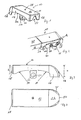
- Fig. 1 shows a bearing body 11 a Radarmspitze 10 with a base plate 12, a side wall 14, a front wall 16 and a connection wall 18.
- the illustrated bearing body 11 is fixed with its connection wall 18 at one end of the Radarms, for example by welding.
- the connection wall 18 has in its center a V-shaped recess 20 into which a corresponding projection on the Radarm can engage to position the bearing body 11 on the Radarm.
- the side wall 14 has laterally a curved contour 22, wherein the contour has a greater height at its end facing the front wall 16 and the connecting wall 18 end.
- the base plate 12 is set or integral with this trained.
- the front wall 16 has a height H, which is greater than the height h of the connecting wall (see. Fig. 3 ).
- a bearing projection 24 Central to the base plate, a bearing projection 24 is arranged, which has a substantially rectangular shape.
- the bearing projection 24 has a through hole 26 which extends transversely to the longitudinal direction of the load arm.
- the bearing projection 24 may be integrally formed with the base plate 12 or to this, for example, by a bore 28, be screwed.
- Fig. 2 shows the Radarmspitze Fig. 1
- the wheel arm 30 has a substantially rectangular cross-section, at whose end-side end the Radarmspitze 10 is attached with its connection wall 18.
- the side walls 14 of the Radarmspitze are coplanar and connected in alignment with the side walls 32 of the radar arm.
- an arm 35 of the rocker for the load wheels 36, 38 can be seen below the crosswinds 14, an arm 35 of the rocker for the load wheels 36, 38 can be seen.
- the arm 35 of the rocker is mounted centrally via a shaft 40 in the bearing projection 24 and its through hole 26.
- the load wheels 36 and 38 are each rotatably supported by bearing elements 42 and 44 at the ends of the arm 35 of the rocker.
- the arm 35 of the rocker abuts approximately in the areas A on an underside of the side wall 14.
- the arrangement of the arm 35 of the rocker below the side wall 14 is possible because the rocker is mounted on the bearing projection 24 and not within the side wall 14th
- Fig. 1 As well in Fig. 1 as well as in Fig. 2 is not shown side wall and not shown side of the rocker corresponding to the side wall 14 and formed according to the arm 35 of the rocker.
- Fig. 3 shows the Radarmspitze invention in a view from the side.
- the front wall 16 has a greater height H than the connecting wall 18 with a height h.
- Approximately in the middle of the base plate 12 of the bearing projection 24 is arranged with its through hole 26.
- the front wall has an arcuate contour 46 at its front, wherein the contour 46 rises approximately vertically on the lower side of the front wall and merges with an arc in the approximately horizontal base plate 12.
- the front wall 16 bends inward, in the direction of the bearing projection 24, wherein a significant portion of the pulse occurring in the collision is absorbed by a plastic deformation of the front wall 16 and the base plate 12.
- the bearing projection 24 and the stop surfaces A formed by the side wall 14 are not changed by such a rear-end collision in their position, so that a further smooth operation with the truck is possible.
- Fig. 4 shows the Radarmspitze in a plan view, in which it can be seen that the front wall 16 with its forward-facing end has a portion 50 which has a width b which is smaller than the total width B of Radarmspitze.
- the front portion 50 each merges with an arcuate portion 48 in the side wall.
- the contour of the front wall 16 is designed such that in a collision at full speed at nominal load, the energy occurring in a collision can be reduced by a plastic deformation of the front wall and damage to other components or components is prevented on the truck.
- the front wall 16 is designed so that the vehicle remains operational even with multiple collisions.
Landscapes
- Engineering & Computer Science (AREA)
- Transportation (AREA)
- Structural Engineering (AREA)
- Civil Engineering (AREA)
- Life Sciences & Earth Sciences (AREA)
- Geology (AREA)
- Mechanical Engineering (AREA)
- Handcart (AREA)
- Rolling Contact Bearings (AREA)
Abstract
Description
- Die vorliegende Erfindung betrifft ein Flurförderzeug mit einem Paar von Radarmen. Die vorliegende Erfindung betrifft insbesondere Spreizenstapler und Schubmaststapler, die ein Paar von Radarmen aufweisen.
- Die bekannten Flurförderzeuge mit Radarmen besitzen an den freien Enden der Radarme jeweils eine Radarmspitze, von denen jede einen mit dem Radarm verbundenen Lagerkörper und ein Paar von Lasträdern oder Lastrollen aufweist.
- Aus
DE 10 2008 034 614 A1 ist ein Flurförderzeug mit Radarmen bekannt geworden, die mit Hilfe von Adapterblöcken an einem Fahrzeugrahmen befestigt sind. Das freie Ende der Radarme weist eine U-förmige Halterung auf, wobei die Schenkel der Halterung mit den Radarmen verbunden sind und die Verbindung zwischen den Schenkeln das freie Ende der Radarme bildet. Die Lasträder sind zwischen den U-förmigen Schenkeln angeordnet. - Aus
US 2008/0308359 A1 ist eine Radarmspitze für ein Flurförderzeug bekannt geworden, die eine Ausnehmung aufweist, in der eine Wippe schwenkbar angeordnet ist. Die seitliche Begrenzung der Radarme erfolgt hierbei durch ein Paar von Außenwänden an der Radarmspitze, zwischen denen die Wippe angeordnet ist. - Der Erfindung liegt die Aufgabe zugrunde, ein Flurförderzeug bereitzustellen, dass bei einer möglichst großen Breite der Lasträder möglichst schmale Radarme besitzt.
- Erfindungsgemäß wird die Aufgabe durch ein Flurförderzeug mit den Merkmalen aus Anspruch 1 gelöst. Vorteilhafte Ausgestaltungen bilden den Gegenstand der Unteransprüche.
- Das erfindungsgemäße Flurförderzeug besitzt ein Paar von Radarmen, wie dies beispielsweise bei Spreizenstaplern und bei Schubmaststaplern der Fall ist. Die Radarme sind an ihren freien Enden jeweils mit einer Radarmspitze ausgestattet, die einstückig mit dem Radarm ausgebildet oder als separates Bauteil mit dem Radarm verbunden sein kann. Jede Radarmspitze weist einen Lagerkörper und ein Paar von Lasträdern auf. Bei der vorliegenden Anmeldung wird nicht zwischen Lasträdern und Lastrollen unterschieden, sondern der Begriff Lastrad durchgehend verwendet. Die Lasträder sind jeweils an einem Ende einer Wippe drehbar gelagert, wobei die Wippe in einem zwischen den Lasträdern liegenden Bereich schwenkbar an dem Lagerkörper der Radarmspitze gelagert ist. Erfindungsgemäß besitzt der Lagerkörper einen Lagervorsprung, an dem die Wippe derart gelagert ist, dass die Wippe die Radarmspitze seitlich begrenzt. Die seitliche Begrenzung der Radarmspitze bezieht sich hierbei auf die Längsrichtung der Radarme. Im Gegensatz zu den bekannten Lösungen, bildet bei der erfindungsgemäßen Ausgestaltung der Radarmspitze eine Außenseite der Wippe die seitliche Begrenzung der Radarmspitze. Erreicht wird dies, indem die Wippe an einem Lagervorsprung des Lagerkörpers schwenkbar befestigt ist und nicht, wie aus dem Stand der Technik bekannt, an den Seitenwänden der Radarmspitze.
- In einer bevorzugten Weiterbildung besitzt der Lagerkörper zwei einander gegenüberliegende Seitenwände quer zu einer Längsrichtung des Radarms, wobei der Lagervorsprung derart angeordnet ist, dass die Seitenwände jeweils oberhalb der Wippe angeordnet sind. Bei dieser bevorzugten Ausgestaltung der Radarmspitze erstrecken sich die Seitenwände nicht über die gesamte Höhe der Radarmspitze, sondern sind derart ausgebildet, dass sie oberhalb der Wippe sich befinden, und so für die Wippe eine größere Breite zur Verfügung steht.
- In einer bevorzugten Ausgestaltung fluchtet die Außenseite der Seitenwände im Wesentlichen mit einer Außenseite der Wippe. Auf diese Weise können die an der Wippe drehbar gelagerten Lasträder bei gleicher Gesamtbreite der Lastarme breiter ausgebildet werden und besitzen somit ein besseres Rollverhalten.
- In einer bevorzugten Ausgestaltung bilden die Seitenwände, und hier insbesondere die Seitenwände mit ihrem nach unten stehenden Rand, Anschläge für die Wippe, um eine Schwenkbewegung der Wippe zu begrenzen.
- Während in einer bevorzugten Ausgestaltung die Seitenwände oberhalb der Wippe angeordnet sind, sind die an der Wippe gelagerten Lasträder teilweise seitlich von der Seitenwand des Lagerkörpers überdeckt.
- In einer bevorzugten Ausgestaltung der Radarmspitze besitzt der Lagerkörper eine im Wesentlichen rechteckige Form, wobei der Lagerkörper eine Grundplatte mit einer zum Radarm weisenden Anschlusswand und zwei seitlichen Seitenwänden aufweist, zwischen denen der Lagervorsprung auf der Grundplatte angeordnet ist. Die Kraftübertragung der erfindungsgemäßen Radarmspitze erfolgt im Wesentlichen über den Lagervorsprung und die Grundplatte hin zu der Anschlusswand, von wo die Kraft in den Radarm eingeleitet wird. Durch den Kraftfluss über die Grundplatte des Lagerkörpers kann ohne Stabilitätsverlust für die Radarmspitze teilweise auf die Seitenwände verzichtet werden, wodurch die Radarmspitze bei gleicher Breite der Lasträder schmaler baut oder bei vorgegebener Breite der Radarmspitze breitere Lasträder verwendet werden können.
- In einer bevorzugten Ausgestaltung des Lagerkörpers überragt der Lagervorsprung die Seitenwände, so dass seitlich des Lagerkörpers die Wippe und die Seitenwände einen Abschluss für die Radarmspitze bilden können.
- In einer bevorzugten Ausgestaltung besitzen die Seitenwände jeweils eine geschwungene Kontur, die eine Anschlagfläche für die Wippe bildet, um die Schwenkbewegung der Wippe zu begrenzen.
- In einer bevorzugten Ausgestaltung weist die Wippe zwei Arme auf, zwischen denen die Lasträder angeordnet sind. Die Arme der Wippe können beispielsweise als flache, plattenförmige Elemente ausgebildet sein, zwischen denen die Lasträder drehbar gelagert sind. Bevorzugt ist im montierten Zustand der Wippe der Lagervorsprung zwischen den Armen der Wippe angeordnet.
- In einer weiteren bevorzugten Ausgestaltung besitzt der Lagerkörper an seinem von dem Radarm fortweisenden Ende eine Frontwand, die in Längsrichtung eine gebogene Kontur besitzt, derart, dass der Übergang von der Grundplatte zur Frontwand auf der von den Lasträdern fortweisenden Seite einen bogenförmigen Verlauf besitzt. Der gebogene Übergang zwischen Frontwand und Grundplatte erleichtert einerseits ein Unterfahren einer aufzunehmenden Last. Gleichzeitig erlaubt eine derart ausgebildete Frontwand eine Deformation der Radarmspitze über die Grundplatte abzufangen, so dass die Radarmspitze weiterhin funktionsfähig bleibt.
- Um die bei einer Kollision auftretenden Kräfte gut aufnehmen zu können, und einen weiteren Betrieb der Radarmspitze sicherzustellen, besitzt bevorzugt die Frontwand eine geringere Wandstärke als die Grundplatte. Hierdurch treten dann bevorzugt plastische Verformungen in der Frontwand auf, wodurch ein Teil des Impulses bereits abgefangen wird.
- In einer weiteren bevorzugten Ausgestaltung verjüngt sich die Frontwand seitlich bezogen auf die Längsrichtung der Radarme zum freien Ende hin. Diese Verjüngung erlaubt ein leichteres Aufnehmen von Lasten, da die Radarmspitze seitlich nicht an einer aufzunehmenden Last hängenbleiben kann. Auch bei einer Kollision erlaubt die verjüngte Spitze ein besseres Aufnehmen des Stoßimpulses.
- Eine vorteilhafte Ausgestaltung der Erfindung wird nachfolgend anhand der Figuren näher erläutert. Es zeigt
- Fig. 1
- die erfindungsgemäße Radarmspitze in einer perspektivischen Ansicht schräg auf eine Anschlusswand,
- Fig. 2
- eine perspektivische Ansicht der am Radarm montierten Radarmspitze,
- Fig. 3
- eine Ansicht der Radarmspitze von der Seite und
- Fig. 4
- eine Draufsicht auf die Radarmspitze.
-
Fig. 1 zeigt einen Lagerkörper 11 einer Radarmspitze 10 mit einer Grundplatte 12, einer Seitenwand 14, einer Frontwand 16 sowie einer Anschlusswand 18. Der dargestellte Lagerkörper 11 wird mit seiner Anschlusswand 18 an einem Ende des Radarms befestigt, beispielsweise durch Verschweißen. Zur besseren Orientierung der Radarmspitze an dem Radarm besitzt die Anschlusswand 18 in ihrer Mitte eine V-förmige Aussparung 20, in die ein entsprechender Vorsprung an dem Radarm eingreifen kann, um den Lagerkörper 11 an dem Radarm zu positionieren. Die Seitenwand 14 besitzt seitlich eine geschwungene Kontur 22, wobei die Kontur an ihrem zur Fronwand 16 und der Anschlusswand 18 weisenden Ende eine größere Höhe besitzt. An die Frontwand 16 ist die Grundplatte 12 gesetzt oder einstückig mit dieser ausgebildet. Die Frontwand 16 besitzt eine Höhe H, die größer ist als die Höhe h der Anschlusswand (vgl.Fig. 3 ). - Zentral an der Grundplatte ist ein Lagervorsprung 24 angeordnet, der eine im Wesentlichen quaderförmige Form besitzt. Der Lagervorsprung 24 besitzt eine Durchgangsbohrung 26, die sich quer zur Längsrichtung des Lastarms erstreckt. Der Lagervorsprung 24 kann einstückig mit der Grundplatte 12 ausgebildet sein oder an diese, beispielsweise durch eine Bohrung 28, angeschraubt sein.
-
Fig. 2 zeigt die Radarmspitze ausFig. 1 mit vollständig montierten Rädern an einem abschnittsweise dargestellten Radarm 30. Der Radarm 30 besitzt einen im Wesentlichen rechteckigen Querschnitt, an dessen stirnseitigem Ende die Radarmspitze 10 mit ihrer Anschlusswand 18 befestigt ist. Die Seitenwände 14 der Radarmspitze sind koplanar und fluchtend mit den Seitenwänden 32 des Radarms verbunden. - Unterhalb der Seitenwinde 14 ist ein Arm 35 der Wippe für die Lasträder 36, 38 zu erkennen. Der Arm 35 der Wippe ist zentral über eine Welle 40 in dem Lagervorsprung 24 und dessen Durchgangsbohrung 26 gelagert. Die Lasträder 36 und 38 sind jeweils über Lagerelemente 42 bzw. 44 an den Enden des Arms 35 der Wippe drehbar gelagert. Wichtig an der Darstellung in
Fig. 2 ist, dass der Arm 35 der Wippe ungefähr in den Bereichen A an einer Unterseite der Seitenwand 14 anschlägt. Die Anordnung des Arms 35 der Wippe unterhalb der Seitenwand 14 ist möglich, da die Wippe an dem Lagervorsprung 24 gelagert ist und nicht innerhalb der Seitenwand 14. - Sowohl in
Fig. 1 als auch inFig. 2 ist die nicht dargestellte Seitenwand und die nicht dargestellte Seite der Wippe entsprechend der Seitenwand 14 bzw. entsprechend dem Arm 35 der Wippe ausgebildet. -
Fig. 3 zeigt die erfindungsgemäße Radarmspitze in einer Ansicht von der Seite. Wie bereits erwähnt, besitzt die Frontwand 16 eine größere Höhe H als die Anschlusswand 18 mit einer Höhe h. Ungefähr mittig an der Grundplatte 12 ist der Lagervorsprung 24 mit seiner Durchgangsbohrung 26 angeordnet. Deutlich zu erkennen inFig. 3 ist, dass die Frontwand an ihrer Vorderseite eine bogenförmige Kontur 46 besitzt, wobei die Kontur 46 an der unteren Seite der Frontwand annähernd senkrecht ansteigt und mit einem Bogen in die annähernd horizontale Grundplatte 12 übergeht. Bei einem Auffahrunfall des Flurförderzeugs biegt sich die Frontwand 16 nach innen, in Richtung des Lagervorsprungs 24, wobei ein nicht unerheblicher Teil des bei der Kollision auftretenden Impulses durch eine plastische Verformung der Frontwand 16 und die Grundplatte 12 aufgenommen wird. - Der Lagervorsprung 24 und die von der Seitenwand 14 gebildeten Anschlagflächen A werden durch einen solchen Auffahrunfall in ihrer Position nicht verändert, so dass ein weiterer reibungsloser Betrieb mit dem Flurförderzeug möglich ist.
-
Fig. 4 zeigt die Radarmspitze in einer Draufsicht, in der zu erkennen ist, dass die Frontwand 16 mit ihrem nach vorn weisenden Ende einen Abschnitt 50 aufweist, der eine Breite b besitzt, die kleiner ist als die Gesamtbreite B der Radarmspitze. Der Frontabschnitt 50 geht jeweils mit einem bogenförmigen Abschnitt 48 in die Seitenwand über. - Die Kontur der Frontwand 16 ist derart ausgebildet, dass bei einer Kollision mit voller Geschwindigkeit bei Nennlast die bei einer Kollision auftretende Energie durch eine plastische Verformung der Frontwand abgebaut werden kann und eine Beschädigung von weiteren Bauteilen oder Komponenten an dem Flurförderzeug verhindert wird. Dabei ist die Frontwand 16 so ausgelegt, dass das Fahrzeug auch bei mehreren Kollisionen betriebsfähig bleibt.
Claims (13)
- Flurförderzeug mit einem Paar von Radarmen (30), die an ihrem freien Ende jeweils eine Radarmspitze (10) aufweisen, von denen jede einen Lagerkörper (11) und ein Paar von Lasträdern (36, 38) aufweist, wobei die Lasträder (36, 38) jeweils an einer Wippe (34) drehbar gelagert sind und die Wippe (34) in einem zwischen den Lasträdern (36, 38) liegenden Bereich (40) schwenkbar an dem Lagerkörper (11) gelagert ist,
dadurch gekennzeichnet, dass
der Lagerkörper (11) einen Lagervorsprung (24) aufweist, an dem die Wippe (34) derart gelagert ist, dass die Wippe die Radarmspitze (10) seitlich begrenzt. - Flurförderzeug nach Anspruch 1, dadurch gekennzeichnet, dass der Lagerkörper (11) zwei einander gegenüberliegende Seitenwände (14) quer zu einer Längsrichtung des Radarms (30) aufweist, wobei der Lagervorsprung (24) derart angeordnet ist, dass die Seitenwände (14) jeweils oberhalb der Wippe (34) angeordnet sind.
- Flurförderzeug nach Anspruch 2, dadurch gekennzeichnet, dass die Außenseite der Seitenwände (14) im Wesentlichen mit der Außenseite der Wippe (34) fluchten.
- Flurförderzeug nach Anspruch 2 oder 3, dadurch gekennzeichnet, dass die Seitenwände (14) einen Anschlag (A) für die Wippe (34) bilden.
- Flurförderzeug nach einem der Ansprüche 2 bis 4, dadurch gekennzeichnet, dass die Seitenwände (14) die Lasträder (36, 38) teilweise seitlich überdecken.
- Flurförderzeug nach einem der Ansprüche 1 bis 5, dadurch gekennzeichnet, dass der Lagerkörper (11) eine im Wesentlichen rechteckige Form besitzt, wobei der Lagerkörper (11) eine Grundplatte (12) mit einer zum Radarm (30) weisenden Anschlusswand (18) und zwei seitliche Seitenwände (14) aufweist, zwischen denen der Lagervorsprung (24) auf der Grundplatte (12) angeordnet ist.
- Flurförderzeug nach Anspruch 6, dadurch gekennzeichnet, dass der Lagervorsprung (24) die Seitenwände (14) überragt.
- Flurförderzeug nach Anspruch 6 oder 7, dadurch gekennzeichnet, dass die Seitenwände (14) jeweils eine geschwungene Kontur (22) besitzen.
- Flurförderzeug nach einem der Ansprüche 1 bis 8, dadurch gekennzeichnet, dass die Wippe (34) zwei Arme (35) aufweist, zwischen denen die Lasträder (36, 38) angeordnet sind.
- Flurförderzeug nach Anspruch 9, dadurch gekennzeichnet, dass der Lagervorsprung (24) zwischen den Armen (35) der Wippe angeordnet ist.
- Flurförderzeug nach einem der Ansprüche 1 bis 10, dadurch gekennzeichnet, dass der Lagerkörper (11) an seiner von dem Radarm fortweisenden Ende eine Frontwand (16) besitzt, und in Längsrichtung eine gebogene Kontur (46) aufweist, derart, dass der Übergang von der Grundplatte (12) zu der Frontwand (16) auf der von den Lasträdern (36, 38) fortweisenden Seite einen bogenförmigen Verlauf besitzt.
- Flurförderzeug nach Anspruch 11, dadurch gekennzeichnet, dass die Frontwand (16) eine geringe Wandstärke als die Grundplatte (12) besitzt.
- Flurförderzeug nach Anspruch 11 oder 12, dadurch gekennzeichnet, dass die Frontwand (16) seitlich bezogen auf die Längsrichtung der Radarme (30) sich zum freien Ende (50) der Frontwand hin verjüngt.
Applications Claiming Priority (1)
| Application Number | Priority Date | Filing Date | Title |
|---|---|---|---|
| DE102011010693A DE102011010693A1 (de) | 2011-02-08 | 2011-02-08 | Flurförderzeug mit einem Paar von Radarmen |
Publications (2)
| Publication Number | Publication Date |
|---|---|
| EP2484626A1 true EP2484626A1 (de) | 2012-08-08 |
| EP2484626B1 EP2484626B1 (de) | 2013-05-08 |
Family
ID=45560669
Family Applications (1)
| Application Number | Title | Priority Date | Filing Date |
|---|---|---|---|
| EP12000476.7A Active EP2484626B1 (de) | 2011-02-08 | 2012-01-25 | Flurförderzeug mit einem Paar von Radarmen |
Country Status (3)
| Country | Link |
|---|---|
| US (1) | US8540253B2 (de) |
| EP (1) | EP2484626B1 (de) |
| DE (1) | DE102011010693A1 (de) |
Families Citing this family (3)
| Publication number | Priority date | Publication date | Assignee | Title |
|---|---|---|---|---|
| JP5904612B1 (ja) * | 2014-12-25 | 2016-04-13 | ニチユ三菱フォークリフト株式会社 | フォークリフト |
| US9505595B1 (en) * | 2015-11-06 | 2016-11-29 | James Nelson Smith | Rapid delivery pallet jack system |
| US11104558B2 (en) | 2018-12-27 | 2021-08-31 | Crown Equipment Corporation | Load wheel assembly for preventing axial and rotational movement of an axle |
Citations (8)
| Publication number | Priority date | Publication date | Assignee | Title |
|---|---|---|---|---|
| US3778080A (en) * | 1972-05-15 | 1973-12-11 | Raymond Corp | Lift truck load wheel arrangement |
| JP2000007294A (ja) * | 1998-06-19 | 2000-01-11 | Nippon Yusoki Co Ltd | リフトトラックのロードホイール支持装置 |
| JP2000044185A (ja) * | 1998-08-03 | 2000-02-15 | Nippon Yusoki Co Ltd | リフトトラック |
| JP2004035231A (ja) * | 2002-07-05 | 2004-02-05 | Nippon Yusoki Co Ltd | リフトトラック |
| USD499853S1 (en) * | 2003-09-09 | 2004-12-14 | The Raymond Corporation | Base leg wheel cover for a material handling vehicle |
| JP2006056646A (ja) * | 2004-08-19 | 2006-03-02 | Nippon Yusoki Co Ltd | リフトトラック |
| US20080308359A1 (en) | 2007-06-15 | 2008-12-18 | Waltz Lucas B | Quick change load wheel assembly |
| DE102008034614A1 (de) | 2008-07-23 | 2010-01-28 | Jungheinrich Ag | Flurförderzeug mit Radarmen |
Family Cites Families (3)
| Publication number | Priority date | Publication date | Assignee | Title |
|---|---|---|---|---|
| US3626863A (en) * | 1969-07-15 | 1971-12-14 | Demag Ag | Railway vehicle stub axle truck |
| SE0401297L (sv) * | 2004-05-19 | 2005-11-01 | Bt Ind Ab | Stödbenstruck |
| US8338748B2 (en) | 2007-07-17 | 2012-12-25 | Lincoln Global, Inc. | Tandem welding carriage with changeable wheel configuration and modular construction |
-
2011
- 2011-02-08 DE DE102011010693A patent/DE102011010693A1/de not_active Withdrawn
-
2012
- 2012-01-25 EP EP12000476.7A patent/EP2484626B1/de active Active
- 2012-02-07 US US13/367,974 patent/US8540253B2/en not_active Expired - Fee Related
Patent Citations (8)
| Publication number | Priority date | Publication date | Assignee | Title |
|---|---|---|---|---|
| US3778080A (en) * | 1972-05-15 | 1973-12-11 | Raymond Corp | Lift truck load wheel arrangement |
| JP2000007294A (ja) * | 1998-06-19 | 2000-01-11 | Nippon Yusoki Co Ltd | リフトトラックのロードホイール支持装置 |
| JP2000044185A (ja) * | 1998-08-03 | 2000-02-15 | Nippon Yusoki Co Ltd | リフトトラック |
| JP2004035231A (ja) * | 2002-07-05 | 2004-02-05 | Nippon Yusoki Co Ltd | リフトトラック |
| USD499853S1 (en) * | 2003-09-09 | 2004-12-14 | The Raymond Corporation | Base leg wheel cover for a material handling vehicle |
| JP2006056646A (ja) * | 2004-08-19 | 2006-03-02 | Nippon Yusoki Co Ltd | リフトトラック |
| US20080308359A1 (en) | 2007-06-15 | 2008-12-18 | Waltz Lucas B | Quick change load wheel assembly |
| DE102008034614A1 (de) | 2008-07-23 | 2010-01-28 | Jungheinrich Ag | Flurförderzeug mit Radarmen |
Also Published As
| Publication number | Publication date |
|---|---|
| US8540253B2 (en) | 2013-09-24 |
| DE102011010693A1 (de) | 2012-08-09 |
| US20130038034A1 (en) | 2013-02-14 |
| EP2484626B1 (de) | 2013-05-08 |
Similar Documents
| Publication | Publication Date | Title |
|---|---|---|
| DE102007049864B4 (de) | Sitzgestell eines Kraftfahrzeugsitzes mit einem Sitzträger, der zwei Seitenteile hat | |
| DE10221311B4 (de) | Niederhub-Flurförderzeug | |
| DE102012006060B4 (de) | Entriegelungsvorrichtung für das Verriegelungsmittel einer Sitzschiene | |
| WO2015110230A1 (de) | Bauteilanbindung mit querkraftabstützender stützfläche | |
| EP2484626B1 (de) | Flurförderzeug mit einem Paar von Radarmen | |
| EP3183467B1 (de) | Aggregatlager-anordnung | |
| EP3650312A1 (de) | Achsträger mit vorrichtung zum positionieren eines lenkgetriebes | |
| EP2759422B1 (de) | Anhängekupplung | |
| EP0407740B1 (de) | Wagenheber | |
| DE102010044055A1 (de) | Fahrzeugsitzgestell | |
| DE102016006848B4 (de) | Achsträger für ein mehrspuriges Kraftfahrzeug | |
| DE102008061854A1 (de) | Scharnier | |
| EP2147890B1 (de) | Flurförderzeug mit Radarmen | |
| EP1616780B1 (de) | Radaufhängung für ein lenkbares Fahrzeugrad | |
| DE202012010661U1 (de) | Bindung für Gleitbrett mit Stützglied | |
| EP1571013B1 (de) | Gefederte Aufhängung einer Starrachse am Fahrgestell-Rahmen eines Fahrzeuges, insbesondere Lastkraftwagens oder Omnibusses | |
| DE102007012118B4 (de) | Einstellpuffer für Kraftfahrzeuge | |
| DE102007049432B4 (de) | Längseinsteller für einen Fahrzeugsitz | |
| EP2998265A1 (de) | Lastteil für ein flurförderzeug | |
| EP2934948B1 (de) | Aufnahme für ein zumindest im wesentlichen quaderförmiges behältnis in einem innenraum eines kraftfahrzeugs | |
| AT514895B1 (de) | Bindungstragplatte zum Verbinden einer Schibindung mit einem Schi sowie damit ausgestatteter Schi | |
| DE102008029918A1 (de) | Kupplungsvorrichtung | |
| EP2361530A1 (de) | Verbindungselement für einreihige Wandschienen | |
| DE337304C (de) | Daempfungsvorrichtung fuer die an der Verbindungsstelle zweier Fahrzeuge auftretenden Kraefte | |
| DE102006043923B4 (de) | Lokomotivkasten |
Legal Events
| Date | Code | Title | Description |
|---|---|---|---|
| PUAI | Public reference made under article 153(3) epc to a published international application that has entered the european phase |
Free format text: ORIGINAL CODE: 0009012 |
|
| AK | Designated contracting states |
Kind code of ref document: A1 Designated state(s): AL AT BE BG CH CY CZ DE DK EE ES FI FR GB GR HR HU IE IS IT LI LT LU LV MC MK MT NL NO PL PT RO RS SE SI SK SM TR |
|
| AX | Request for extension of the european patent |
Extension state: BA ME |
|
| 17P | Request for examination filed |
Effective date: 20120920 |
|
| GRAP | Despatch of communication of intention to grant a patent |
Free format text: ORIGINAL CODE: EPIDOSNIGR1 |
|
| GRAS | Grant fee paid |
Free format text: ORIGINAL CODE: EPIDOSNIGR3 |
|
| GRAA | (expected) grant |
Free format text: ORIGINAL CODE: 0009210 |
|
| AK | Designated contracting states |
Kind code of ref document: B1 Designated state(s): AL AT BE BG CH CY CZ DE DK EE ES FI FR GB GR HR HU IE IS IT LI LT LU LV MC MK MT NL NO PL PT RO RS SE SI SK SM TR |
|
| REG | Reference to a national code |
Ref country code: GB Ref legal event code: FG4D Free format text: NOT ENGLISH |
|
| REG | Reference to a national code |
Ref country code: CH Ref legal event code: EP Ref country code: AT Ref legal event code: REF Ref document number: 610987 Country of ref document: AT Kind code of ref document: T Effective date: 20130515 |
|
| REG | Reference to a national code |
Ref country code: IE Ref legal event code: FG4D Free format text: LANGUAGE OF EP DOCUMENT: GERMAN |
|
| REG | Reference to a national code |
Ref country code: DE Ref legal event code: R096 Ref document number: 502012000017 Country of ref document: DE Effective date: 20130704 |
|
| REG | Reference to a national code |
Ref country code: SE Ref legal event code: TRGR |
|
| REG | Reference to a national code |
Ref country code: LT Ref legal event code: MG4D |
|
| REG | Reference to a national code |
Ref country code: NL Ref legal event code: VDEP Effective date: 20130508 |
|
| PG25 | Lapsed in a contracting state [announced via postgrant information from national office to epo] |
Ref country code: GR Free format text: LAPSE BECAUSE OF FAILURE TO SUBMIT A TRANSLATION OF THE DESCRIPTION OR TO PAY THE FEE WITHIN THE PRESCRIBED TIME-LIMIT Effective date: 20130809 Ref country code: NO Free format text: LAPSE BECAUSE OF FAILURE TO SUBMIT A TRANSLATION OF THE DESCRIPTION OR TO PAY THE FEE WITHIN THE PRESCRIBED TIME-LIMIT Effective date: 20130808 Ref country code: PT Free format text: LAPSE BECAUSE OF FAILURE TO SUBMIT A TRANSLATION OF THE DESCRIPTION OR TO PAY THE FEE WITHIN THE PRESCRIBED TIME-LIMIT Effective date: 20130909 Ref country code: SI Free format text: LAPSE BECAUSE OF FAILURE TO SUBMIT A TRANSLATION OF THE DESCRIPTION OR TO PAY THE FEE WITHIN THE PRESCRIBED TIME-LIMIT Effective date: 20130508 Ref country code: IS Free format text: LAPSE BECAUSE OF FAILURE TO SUBMIT A TRANSLATION OF THE DESCRIPTION OR TO PAY THE FEE WITHIN THE PRESCRIBED TIME-LIMIT Effective date: 20130908 Ref country code: LT Free format text: LAPSE BECAUSE OF FAILURE TO SUBMIT A TRANSLATION OF THE DESCRIPTION OR TO PAY THE FEE WITHIN THE PRESCRIBED TIME-LIMIT Effective date: 20130508 Ref country code: ES Free format text: LAPSE BECAUSE OF FAILURE TO SUBMIT A TRANSLATION OF THE DESCRIPTION OR TO PAY THE FEE WITHIN THE PRESCRIBED TIME-LIMIT Effective date: 20130819 Ref country code: FI Free format text: LAPSE BECAUSE OF FAILURE TO SUBMIT A TRANSLATION OF THE DESCRIPTION OR TO PAY THE FEE WITHIN THE PRESCRIBED TIME-LIMIT Effective date: 20130508 |
|
| PG25 | Lapsed in a contracting state [announced via postgrant information from national office to epo] |
Ref country code: HR Free format text: LAPSE BECAUSE OF FAILURE TO SUBMIT A TRANSLATION OF THE DESCRIPTION OR TO PAY THE FEE WITHIN THE PRESCRIBED TIME-LIMIT Effective date: 20130508 Ref country code: PL Free format text: LAPSE BECAUSE OF FAILURE TO SUBMIT A TRANSLATION OF THE DESCRIPTION OR TO PAY THE FEE WITHIN THE PRESCRIBED TIME-LIMIT Effective date: 20130508 Ref country code: RS Free format text: LAPSE BECAUSE OF FAILURE TO SUBMIT A TRANSLATION OF THE DESCRIPTION OR TO PAY THE FEE WITHIN THE PRESCRIBED TIME-LIMIT Effective date: 20130508 Ref country code: BG Free format text: LAPSE BECAUSE OF FAILURE TO SUBMIT A TRANSLATION OF THE DESCRIPTION OR TO PAY THE FEE WITHIN THE PRESCRIBED TIME-LIMIT Effective date: 20130808 Ref country code: CY Free format text: LAPSE BECAUSE OF FAILURE TO SUBMIT A TRANSLATION OF THE DESCRIPTION OR TO PAY THE FEE WITHIN THE PRESCRIBED TIME-LIMIT Effective date: 20130508 |
|
| PG25 | Lapsed in a contracting state [announced via postgrant information from national office to epo] |
Ref country code: LV Free format text: LAPSE BECAUSE OF FAILURE TO SUBMIT A TRANSLATION OF THE DESCRIPTION OR TO PAY THE FEE WITHIN THE PRESCRIBED TIME-LIMIT Effective date: 20130508 |
|
| PG25 | Lapsed in a contracting state [announced via postgrant information from national office to epo] |
Ref country code: SK Free format text: LAPSE BECAUSE OF FAILURE TO SUBMIT A TRANSLATION OF THE DESCRIPTION OR TO PAY THE FEE WITHIN THE PRESCRIBED TIME-LIMIT Effective date: 20130508 Ref country code: DK Free format text: LAPSE BECAUSE OF FAILURE TO SUBMIT A TRANSLATION OF THE DESCRIPTION OR TO PAY THE FEE WITHIN THE PRESCRIBED TIME-LIMIT Effective date: 20130508 Ref country code: EE Free format text: LAPSE BECAUSE OF FAILURE TO SUBMIT A TRANSLATION OF THE DESCRIPTION OR TO PAY THE FEE WITHIN THE PRESCRIBED TIME-LIMIT Effective date: 20130508 Ref country code: CZ Free format text: LAPSE BECAUSE OF FAILURE TO SUBMIT A TRANSLATION OF THE DESCRIPTION OR TO PAY THE FEE WITHIN THE PRESCRIBED TIME-LIMIT Effective date: 20130508 |
|
| PG25 | Lapsed in a contracting state [announced via postgrant information from national office to epo] |
Ref country code: NL Free format text: LAPSE BECAUSE OF FAILURE TO SUBMIT A TRANSLATION OF THE DESCRIPTION OR TO PAY THE FEE WITHIN THE PRESCRIBED TIME-LIMIT Effective date: 20130508 Ref country code: RO Free format text: LAPSE BECAUSE OF FAILURE TO SUBMIT A TRANSLATION OF THE DESCRIPTION OR TO PAY THE FEE WITHIN THE PRESCRIBED TIME-LIMIT Effective date: 20130508 |
|
| PLBE | No opposition filed within time limit |
Free format text: ORIGINAL CODE: 0009261 |
|
| STAA | Information on the status of an ep patent application or granted ep patent |
Free format text: STATUS: NO OPPOSITION FILED WITHIN TIME LIMIT |
|
| 26N | No opposition filed |
Effective date: 20140211 |
|
| REG | Reference to a national code |
Ref country code: DE Ref legal event code: R097 Ref document number: 502012000017 Country of ref document: DE Effective date: 20140211 |
|
| BERE | Be: lapsed |
Owner name: JUNGHEINRICH A.G. Effective date: 20140131 |
|
| PG25 | Lapsed in a contracting state [announced via postgrant information from national office to epo] |
Ref country code: LU Free format text: LAPSE BECAUSE OF FAILURE TO SUBMIT A TRANSLATION OF THE DESCRIPTION OR TO PAY THE FEE WITHIN THE PRESCRIBED TIME-LIMIT Effective date: 20140125 |
|
| REG | Reference to a national code |
Ref country code: IE Ref legal event code: MM4A |
|
| PG25 | Lapsed in a contracting state [announced via postgrant information from national office to epo] |
Ref country code: BE Free format text: LAPSE BECAUSE OF NON-PAYMENT OF DUE FEES Effective date: 20140131 Ref country code: IE Free format text: LAPSE BECAUSE OF NON-PAYMENT OF DUE FEES Effective date: 20140125 |
|
| PG25 | Lapsed in a contracting state [announced via postgrant information from national office to epo] |
Ref country code: MC Free format text: LAPSE BECAUSE OF FAILURE TO SUBMIT A TRANSLATION OF THE DESCRIPTION OR TO PAY THE FEE WITHIN THE PRESCRIBED TIME-LIMIT Effective date: 20130508 |
|
| PG25 | Lapsed in a contracting state [announced via postgrant information from national office to epo] |
Ref country code: BE Free format text: LAPSE BECAUSE OF NON-PAYMENT OF DUE FEES Effective date: 20150131 |
|
| REG | Reference to a national code |
Ref country code: CH Ref legal event code: PL |
|
| PG25 | Lapsed in a contracting state [announced via postgrant information from national office to epo] |
Ref country code: CH Free format text: LAPSE BECAUSE OF NON-PAYMENT OF DUE FEES Effective date: 20150131 Ref country code: LI Free format text: LAPSE BECAUSE OF NON-PAYMENT OF DUE FEES Effective date: 20150131 |
|
| REG | Reference to a national code |
Ref country code: FR Ref legal event code: PLFP Year of fee payment: 5 |
|
| PG25 | Lapsed in a contracting state [announced via postgrant information from national office to epo] |
Ref country code: MT Free format text: LAPSE BECAUSE OF FAILURE TO SUBMIT A TRANSLATION OF THE DESCRIPTION OR TO PAY THE FEE WITHIN THE PRESCRIBED TIME-LIMIT Effective date: 20130508 |
|
| PG25 | Lapsed in a contracting state [announced via postgrant information from national office to epo] |
Ref country code: SM Free format text: LAPSE BECAUSE OF FAILURE TO SUBMIT A TRANSLATION OF THE DESCRIPTION OR TO PAY THE FEE WITHIN THE PRESCRIBED TIME-LIMIT Effective date: 20130508 |
|
| PG25 | Lapsed in a contracting state [announced via postgrant information from national office to epo] |
Ref country code: HU Free format text: LAPSE BECAUSE OF FAILURE TO SUBMIT A TRANSLATION OF THE DESCRIPTION OR TO PAY THE FEE WITHIN THE PRESCRIBED TIME-LIMIT; INVALID AB INITIO Effective date: 20120125 Ref country code: TR Free format text: LAPSE BECAUSE OF FAILURE TO SUBMIT A TRANSLATION OF THE DESCRIPTION OR TO PAY THE FEE WITHIN THE PRESCRIBED TIME-LIMIT Effective date: 20130508 |
|
| REG | Reference to a national code |
Ref country code: FR Ref legal event code: PLFP Year of fee payment: 6 |
|
| REG | Reference to a national code |
Ref country code: FR Ref legal event code: PLFP Year of fee payment: 7 |
|
| REG | Reference to a national code |
Ref country code: AT Ref legal event code: MM01 Ref document number: 610987 Country of ref document: AT Kind code of ref document: T Effective date: 20170125 |
|
| PG25 | Lapsed in a contracting state [announced via postgrant information from national office to epo] |
Ref country code: AT Free format text: LAPSE BECAUSE OF NON-PAYMENT OF DUE FEES Effective date: 20170125 |
|
| PG25 | Lapsed in a contracting state [announced via postgrant information from national office to epo] |
Ref country code: MK Free format text: LAPSE BECAUSE OF FAILURE TO SUBMIT A TRANSLATION OF THE DESCRIPTION OR TO PAY THE FEE WITHIN THE PRESCRIBED TIME-LIMIT Effective date: 20130508 |
|
| PG25 | Lapsed in a contracting state [announced via postgrant information from national office to epo] |
Ref country code: AL Free format text: LAPSE BECAUSE OF FAILURE TO SUBMIT A TRANSLATION OF THE DESCRIPTION OR TO PAY THE FEE WITHIN THE PRESCRIBED TIME-LIMIT Effective date: 20130508 |
|
| PGFP | Annual fee paid to national office [announced via postgrant information from national office to epo] |
Ref country code: GB Payment date: 20210128 Year of fee payment: 10 |
|
| GBPC | Gb: european patent ceased through non-payment of renewal fee |
Effective date: 20220125 |
|
| PG25 | Lapsed in a contracting state [announced via postgrant information from national office to epo] |
Ref country code: GB Free format text: LAPSE BECAUSE OF NON-PAYMENT OF DUE FEES Effective date: 20220125 |
|
| PGFP | Annual fee paid to national office [announced via postgrant information from national office to epo] |
Ref country code: SE Payment date: 20260121 Year of fee payment: 15 |
|
| PGFP | Annual fee paid to national office [announced via postgrant information from national office to epo] |
Ref country code: DE Payment date: 20260120 Year of fee payment: 15 |
|
| PGFP | Annual fee paid to national office [announced via postgrant information from national office to epo] |
Ref country code: IT Payment date: 20260130 Year of fee payment: 15 |
|
| PGFP | Annual fee paid to national office [announced via postgrant information from national office to epo] |
Ref country code: FR Payment date: 20260121 Year of fee payment: 15 |