EP2483087B1 - Bande de roulement pour pneu de rigidite amelioree - Google Patents
Bande de roulement pour pneu de rigidite amelioree Download PDFInfo
- Publication number
- EP2483087B1 EP2483087B1 EP10757614.2A EP10757614A EP2483087B1 EP 2483087 B1 EP2483087 B1 EP 2483087B1 EP 10757614 A EP10757614 A EP 10757614A EP 2483087 B1 EP2483087 B1 EP 2483087B1
- Authority
- EP
- European Patent Office
- Prior art keywords
- tread
- cavities
- internal
- external
- grooves
- Prior art date
- Legal status (The legal status is an assumption and is not a legal conclusion. Google has not performed a legal analysis and makes no representation as to the accuracy of the status listed.)
- Active
Links
Images

Classifications
-
- B—PERFORMING OPERATIONS; TRANSPORTING
- B60—VEHICLES IN GENERAL
- B60C—VEHICLE TYRES; TYRE INFLATION; TYRE CHANGING; CONNECTING VALVES TO INFLATABLE ELASTIC BODIES IN GENERAL; DEVICES OR ARRANGEMENTS RELATED TO TYRES
- B60C11/00—Tyre tread bands; Tread patterns; Anti-skid inserts
- B60C11/03—Tread patterns
- B60C11/04—Tread patterns in which the raised area of the pattern consists only of continuous circumferential ribs, e.g. zig-zag
- B60C11/042—Tread patterns in which the raised area of the pattern consists only of continuous circumferential ribs, e.g. zig-zag further characterised by the groove cross-section
-
- B—PERFORMING OPERATIONS; TRANSPORTING
- B60—VEHICLES IN GENERAL
- B60C—VEHICLE TYRES; TYRE INFLATION; TYRE CHANGING; CONNECTING VALVES TO INFLATABLE ELASTIC BODIES IN GENERAL; DEVICES OR ARRANGEMENTS RELATED TO TYRES
- B60C11/00—Tyre tread bands; Tread patterns; Anti-skid inserts
- B60C11/03—Tread patterns
- B60C11/0306—Patterns comprising block rows or discontinuous ribs
- B60C11/0309—Patterns comprising block rows or discontinuous ribs further characterised by the groove cross-section
-
- B—PERFORMING OPERATIONS; TRANSPORTING
- B60—VEHICLES IN GENERAL
- B60C—VEHICLE TYRES; TYRE INFLATION; TYRE CHANGING; CONNECTING VALVES TO INFLATABLE ELASTIC BODIES IN GENERAL; DEVICES OR ARRANGEMENTS RELATED TO TYRES
- B60C11/00—Tyre tread bands; Tread patterns; Anti-skid inserts
- B60C11/03—Tread patterns
- B60C11/032—Patterns comprising isolated recesses
- B60C11/0323—Patterns comprising isolated recesses tread comprising channels under the tread surface, e.g. for draining water
-
- B—PERFORMING OPERATIONS; TRANSPORTING
- B60—VEHICLES IN GENERAL
- B60C—VEHICLE TYRES; TYRE INFLATION; TYRE CHANGING; CONNECTING VALVES TO INFLATABLE ELASTIC BODIES IN GENERAL; DEVICES OR ARRANGEMENTS RELATED TO TYRES
- B60C11/00—Tyre tread bands; Tread patterns; Anti-skid inserts
- B60C11/03—Tread patterns
- B60C11/12—Tread patterns characterised by the use of narrow slits or incisions, e.g. sipes
- B60C11/1204—Tread patterns characterised by the use of narrow slits or incisions, e.g. sipes with special shape of the sipe
- B60C11/1218—Three-dimensional shape with regard to depth and extending direction
-
- B—PERFORMING OPERATIONS; TRANSPORTING
- B60—VEHICLES IN GENERAL
- B60C—VEHICLE TYRES; TYRE INFLATION; TYRE CHANGING; CONNECTING VALVES TO INFLATABLE ELASTIC BODIES IN GENERAL; DEVICES OR ARRANGEMENTS RELATED TO TYRES
- B60C11/00—Tyre tread bands; Tread patterns; Anti-skid inserts
- B60C11/03—Tread patterns
- B60C11/12—Tread patterns characterised by the use of narrow slits or incisions, e.g. sipes
- B60C11/1272—Width of the sipe
- B60C11/1281—Width of the sipe different within the same sipe, i.e. enlarged width portion at sipe bottom or along its length
-
- B—PERFORMING OPERATIONS; TRANSPORTING
- B60—VEHICLES IN GENERAL
- B60C—VEHICLE TYRES; TYRE INFLATION; TYRE CHANGING; CONNECTING VALVES TO INFLATABLE ELASTIC BODIES IN GENERAL; DEVICES OR ARRANGEMENTS RELATED TO TYRES
- B60C11/00—Tyre tread bands; Tread patterns; Anti-skid inserts
- B60C11/03—Tread patterns
- B60C11/13—Tread patterns characterised by the groove cross-section, e.g. for buttressing or preventing stone-trapping
- B60C11/1307—Tread patterns characterised by the groove cross-section, e.g. for buttressing or preventing stone-trapping with special features of the groove walls
Definitions
- the invention relates to treads for tires and more particularly the tread patterns of these belts and the tires provided with such treads whose performance in drainage of the water present on the roadway in rainy weather is made more durable, these treads are not penalized in terms of wear speed.
- sculpture of a tread means here the geometry of the part of the tread intended to come into contact with a roadway, this sculpture being formed by relief elements delimited from each other by cutouts (grooves incisions, wells, cavities).
- groove is meant here a hollow opening on a running surface coming into contact with the roadway, the hollow having an appropriate average width so that the material walls which delimit it are never in contact with one another in the normal conditions of use of the tire.
- the grooves may have any shape seen in cross section and in trace on the running surface and be oriented in any direction. Trace of a groove on the tread surface here means the geometric mean line followed by the ridges formed by said groove on said surface.
- a groove may have open ends towards the outside of the band or be continuous circumferentially.
- incision is meant here a thin slot having a low average width and such that, under certain conditions of stress, the walls of material delimiting it may come, at least partially, in contact with one another during the passage through the area of contact with the road.
- the terms “radial” or “radially” are used to indicate a direction which, when taken on the tire, is a direction perpendicular to the axis of rotation of the tire while, when taken on a tread alone, it corresponds to the direction of the thickness of said strip.
- the word “circumferential” is used to indicate a direction which corresponds to a direction tangent to a circle centered on the axis of rotation of the tire. This same direction corresponds to the longitudinal direction of the tread, which is formed in the manner of a flat strip before incorporation into a tire.
- the total volume of trough (or cavity) of a tread is equal to the sum of all trough volumes opening or not on the tread surface of the strip when new. Some of these depressions can open in contact with a roadway after partial wear of the belt.
- the total volume of a tread is equal to the sum of the total volume of material that can be used while driving before having to remove the tire (either to renew its tread by retreading, or to replace it with a new tire) and the total volume of troughs.
- the total thickness E of a tread corresponds to the thickness of material intended to be worn during rolling. By convention, this total thickness E does not take into account the thickness possibly provided to allow a partial renewal of the grooves by a regrooving operation. This total thickness E is measured on the new tire between the running surface and the external surface of the wear indicators. Radially between the tire crown reinforcement and this total thickness E, there is generally a complementary thickness E * tread.
- the tread of these tires For tires intended for the steering or carrying axles of a heavy goods vehicle, it is customary to provide the tread of these tires with circumferential (or longitudinal) grooves whose depth is equal to the total thickness of the tread. (this total thickness not taking into account count the thickness possibly provided to allow a partial renewal of the grooves).
- This groove depth is generally between 13 and 18 mm on the tires for said axles.
- the depth of the grooves can however be up to 24 mm.
- the total volume of depressions is generally between 15 and 25% of the total volume of the tread to be used during the running (the total volume corresponding to the volume of the tread). material to which said total void volume is added).
- these tires have an effective hollow volume Ve in the contact region which is relatively large in the new state (effective means here potentially likely to be filled by a liquid on the road).
- This volume of hollow opening on the running surface in the contact is on average of the order of 100 cm 3 for a tire of size 315/70 R 22.5.
- the effective hollow volume Ve opening on the running surface in the contact is evaluated when the tire is subjected to its nominal inflating and static crushing conditions as defined by the ETRTO standard.
- grooves or more generally cavities are essential for the drainage of water in contact with a roadway, the resulting decrease in material on the web can significantly affect the wear performance of this web and consequently reduce the service life.
- Other performance of the tire can also be affected, including performance in behavior, noise in rolling, rolling resistance.
- these grooves formed to have a useful depth equal to the height of the band to be used may be the cause of endurance problems. In certain driving conditions, foreign objects such as pebbles can be captured in these grooves and attack the bottom of these grooves and generate the appearance of breaks in the rubber.
- Achieving a plurality of grooves on a tread therefore has the disadvantage of reducing the amount of web material for a given web width and thereby reducing tire service life due to increase in the speed of wear.
- the grooves generate a lowering of the compression and shear stiffness since these grooves delimit portions of material more sensitive to deformation compared to the portions delimited by incisions. Indeed, in the case of incisions the walls of material delimiting these incisions can come into contact with each other at least in the passage in the region of contact with the roadway. This reduction in rigidity, in the case of the presence of grooves, induces an increase in deformations and generates a decrease in the wear performance of the band: greater wear is observed for a fixed distance traveled (this corresponds to an increase in the speed of wear of the band).
- An object of the invention is to provide a tread provided with grooves and incisions to have a performance equal to or greater than the minimum safety performance in drainage and this regardless of the level of wear of this band while significantly improving wear life performance, reducing rolling resistance and improving tread wear endurance.
- a tire tread according to claim 1 It is a tread for a tire of total thickness E having a running surface intended to come into contact with the tire. pavement, this strip comprising at least two wear layers in its thickness, that is to say at least a first and a second wear layers in its thickness.
- the first layer is the outermost layer when the strip is new and comes into first contact with the roadway.
- this band comprises at least one continuous groove formed by a plurality of external cavities opening on the running surface in the new state and a plurality of internal cavities, the latter being placed radially and entirely at the inside of the running surface in new condition.
- wear layer is meant, in the present application, a portion of the tread bound to the maximum depth of the grooves in said wear layer.
- a wear layer has a thickness which is less than the total thickness of the tread and which is equal to the maximum depth of the grooves or cavities present in this wear layer.
- the treads of the invention comprise at least two wear layers in which some of the grooves or cavities are formed only in one of said layers. It is of course possible and even advantageous that in this configuration, each wear layer becomes active before a previous wear layer is totally worn; in such a case there is overlap between at least two wear layers.
- a wear layer becomes active when the cavities or grooves formed in this layer open on the running surface of the tire in contact with the roadway to drain the water present on said roadway during rainy weather.
- the first wear layer corresponds to the radially outermost part of the tread when new.
- the first wear layer extends from the running surface of the strip in the new state, in the thickness of the tread to the radially more inside the outer cavities.
- radially the innermost is meant the most distant points of the running surface when new.
- another wear layer is defined as the layer extending in the depth of the strip to the radially innermost points of the internal cavities of the other wear layer. considered. This layer extends from the radially outermost points of the internal cavities.
- the external cavities have an average depth P1 less than the total thickness E of the tread, an average length L1 and a cross section, in a plane of section perpendicular to the tread surface, of area S1 (these preferential arrangements apply to all variants described in this document).
- the internal cavities have an average height P2 less than the total thickness E of the tread (this height being measured between the radially outermost points and the radially innermost points of the walls delimiting said cavities ), an average length L2 and a cross section of area S2 (these preferential provisions apply to all variants described in this document).
- All these cavities of the same continuous groove are such that the difference between the average lengths of the internal cavities and the external cavities is at most equal to 20% of the greatest average length (that is to say 0.8 ⁇ L1 / L2 ⁇ 1.2), and the difference in average cross-sectional areas of the internal and external cavities is not more than 20% of the largest mean area (ie 0.8 ⁇ S1 / S2 ⁇ 1.2).
- each external cavity of a continuous groove is connected to at least two internal cavities of the same groove by connecting channels providing continuity between said internal and external cavities.
- Each connecting channel has two ends connected to an internal cavity on the one hand and to an external cavity on the other hand; each connecting channel has cross sections (in a section plane perpendicular to the mean direction of the groove) whose areas are respectively equal to the cross-sectional areas of the inner and outer cavities connected by this connecting channel.
- This band further comprises a plurality of incisions opening on the running surface of the band in the new state, each of said incisions connecting two consecutive external cavities of the same groove and at least two connecting channels and at least an internal cavity.
- Each layer has a thickness at most equal to 75% of the total thickness E of the tread (each wear layer comprising grooves or cavities which are specific to it and which are not found entirely in another layer) ,
- the tread thickness radially outside each internal cavity is greater than 25% of the total thickness E of the tread.
- the external cavities and the internal cavities preferably have mean depths at most equal to 75% of the total thickness E of the tread.
- the groove according to the invention can be likened to a continuous groove opening in a regular and discontinuous manner on the tread surface of the tread when new.
- This groove can take a generally wavy shape cutting the running surface in new condition. It is the presence of rubber material radially outside the internal cavities and radially inside the external cavities which makes it possible to obtain an increase in the rigidity of the compression band in particular.
- the tread according to the invention By reducing the level of surface troughs in the new state, the tread according to the invention also has the advantage of being less sensitive to the retention of pebbles and therefore offers better resistance to groove bottom fractures. caused by the penetration of pebbles into the rubbery material.
- surface hollowing rate is meant here the ratio between the surface of the external cavities open on the running surface and the total surface of said strip. The fact that the internal cavities of the same groove do not open onto the running surface in the new state effectively makes it possible to reduce the level of recesses when new, while having effective drainage in the groove.
- the tread according to the invention is such that internal cavities are arranged in the thickness of the strip to lead to the outside of the tread. the strip after partial wear, this partial wear being less than the total wear of the first wear layer.
- this partial wear being less than the total wear of the first wear layer.
- this overlap distance between the wear layers is less than half the depth P1 of the first cavities.
- This variant has the advantage of ensuring a quasi constant volume of hollow useful for draining the water present in the contact with the roadway and this regardless of the level of wear of the strip.
- each connecting channel connecting an external cavity to an internal cavity of the same groove has a length Li greater than zero and less than the circumferential length L1 of the external cavities .
- Li measures the smallest length in the circumferential direction between one end of the outer cavity and one end of the inner cavity.
- the length Li of each connecting channel is greater than zero and at most equal to 50% of L1.
- the tread is such that the internal and external cavities of two successive wear layers of the same groove do not overlap - in whole or in part - in the direction of the thickness of the tread.
- the band that is to say that they are entirely offset from each other in the mean direction of the groove.
- the average direction of a groove corresponds to the direction in which the groove allows the flow of water when driving on a roadway covered with water; this direction generally corresponds to the direction of greater dimension of the groove.
- the total volume of hollow is at least equal to 7% and at most equal to 12% of the total volume V of the tread.
- the effective cavity volume Ve (in the crushed state) for each wear layer satisfies the following relationship:
- the heights of 0.4 mm and 0.8 mm correspond to average water heights that may be present on a roadway in rainy weather and that it is necessary to be able to drain to maintain a good contact between the tread and the roadway.
- the effective hollow volume Ve in the contact contributes to draining the region of contact between the tread and a roadway.
- the tread comprises at least one groove formed of a plurality of pairs of external cavities which are each extended by a connecting channel, these connecting channels opening into the same internal cavity.
- the volume of this internal cavity may be substantially reduced relative to the volume of the external cavities or adapted by the skilled person according to the desired performance and the tire concerned.
- the effective void volume Ve increases with the level of wear of the tread, thus increasing from one wear layer to the next.
- the tread according to the invention comprises at least one groove, the external cavities of which are each extended at both ends by two connecting channels, these connecting channels each opening into separate internal cavities.
- each internal cavity, as well as the connecting channels which connect this internal cavity to two external cavities are extended radially towards the tread surface of the tread in the new state by an incision to allow the molding and the demolding of the tread according to the invention.
- the tread according to the invention comprises additional cavities located in a third wear layer extending radially inside the second wear layer. These additional cavities are connected to the internal cavities of the second wear layer by additional connecting channels. These additional cavities determine a third level of wear and open on the running surface after wear of the band having virtually eliminated the second cavities.
- An application of this variant is particularly advantageous in the case of tire having treads of great thickness.
- the continuous grooves formed of a succession of external and internal cavities connected by connecting channels can be oriented in any direction on the strip or on the tire (that is to say longitudinally or transversely or obliquely to one or other of these directions).
- grooves according to the invention are oriented essentially in a direction corresponding to the largest dimension of the band: either the longitudinal direction of the band or the circumferential direction when this band equips a tire.
- a strip according to the invention comprises a first plurality of continuous grooves according to the invention in a first direction and a second plurality of continuous grooves according to the invention in a second direction crossing the first direction to form a groove network. cross.
- these first and second plurality of grooves according to the invention are arranged in such a way that the internal cavities of these first and second plurality of grooves are connected together in order to reinforce the network effect. By connected together, it should be understood that fluid flow is possible between the different internal cavities of the two plurality of grooves.
- a strip according to the invention comprises a first plurality of grooves according to the invention in a first direction and a second plurality of grooves according to the invention in a second direction intersecting the first direction to form an array of continuous grooves. cross.
- These first and second plurality of grooves according to the invention can be arranged in such a way that the internal cavities of these first and second plurality of grooves are arranged at different depths so as to obtain, in this case, a substantially constant rate of depression which whatever the level of wear of the band.
- hollow rate it is necessary to understand the ratio between the trough surface on the tread surface considered and the total tread surface at the level of wear considered.
- the internal cavities even though they are connected to external cavities, are not considered to confer a tread surface trough rate before they appear on a new tread surface after wear of the tread.
- internal surface of a strip is meant the surface by which the strip is in contact with the tire it equips. These incisions and channels can easily be made at the time of molding the strip.
- the cross section of this channel is determined so that when opening the channel on the running surface after wear of the strip, a new groove of cross section is formed suitable for a good flow of water present in time. rain on the road.
- This channel is designed to form a new groove opening on the running surface after partial wear at most equal to the thickness of the first wear layer.
- the tread may further comprise means for communicating at least one channel with a plurality of internal cavities of a continuous groove.
- the incisions prolonging the internal and external cavities are provided with means for mechanically locking the relative displacements of the walls facing each other delimiting said incisions.
- Such means can take the form of walls vis-à-vis or reliefs molded on said walls and suitable to cooperate together.
- the invention also relates to a tire provided with a tread defined according to the invention, this tread radially outwardly surmounting a tire casing consisting of a carcass reinforcement and a crown reinforcement.
- the tread of this tire is made as one of the previous variants, some dimensions of the grooves being related to the average length of the contact surface of the belt with the roadway under the nominal conditions of use of the tire, these conditions nominal values are defined in the ETRTO standards or J.A.T.M.A ..
- each circumferentially oriented groove formed of cavities opening on the running surface and of cavities under the running surface at least one external cavity permanently in the contact to allow drainage.
- T is the average length of the area of contact with the roadway under the nominal conditions of use of the tire provided with a tread according to the invention (this average length being obtained by dividing the total area delimited by the external contour of this contact surface by the width W of said surface), it is even more preferred that the average length of the outer cavities of the circumferential grooves is between 25% and 75% of the average length T of the contact surface.
- the tread comprises a plurality of grooves formed of a plurality of external cavities and internal cavities connected by connecting channels oriented in the longitudinal direction of the band, these grooves being arranged in such a way that the outer cavities opening on the running surface in the new state are arranged to be all offset relative to one another and in that the internal cavities are also arranged in such a way that they are all offset by compared to others.
- the advantage of such an arrangement is to limit the reduction of shear stiffness of the band particularly under transverse force (for example in bends).
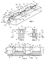
- the figure 1 shows a partial view of the tread surface of a tread comprising a continuous groove according to the invention
- the figure 2 shows a sectional view along a line II-II taken on the tread of the figure 1 ;
- the figure 3 shows a sectional view along a line III-III taken on the tread of the figure 1 ;
- the figure 4 shows a sectional view along a line IV-IV taken on the tread of the figure 1 ;
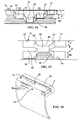
- the figure 5 shows in section an alternative embodiment in which there is provided a continuous channel entirely located under the running surface of the strip
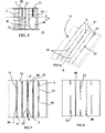
- the figure 6 shows a partial view of a tread according to the invention in new condition
- the figure 7 shows the plan view of the tread surface of the tread of the figure 6 ;
- the figure 8 shows the plan view of the tread surface of the tread of the figure 7 after wear of the band reaching the second wear layer
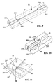
- the figure 9 partially shows a variant of a continuous groove having a pair of external cavities connected to an internal cavity
- the figure 10 partially shows a variant of a continuous groove having an external cavity connected to two internal cavities
- the figure 11 partially shows a variant according to which a tread is provided with grooves according to the invention oriented in two intersecting directions, these grooves being connected together;
- the figure 12 shows a variant of the invention according to which the incisions connecting the internal cavities and the connecting channels to the running surface are provided with wells opening onto the running surface;
- the figure 13 shows in section a variant of the tread according to the invention for which the inclinations of the connecting channels at the ends of an internal cavity are different;
- the figure 14 shows a variant according to which the grooves and incisions follow undulating trajectories
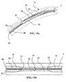
- FIGS. 15a and 15b show a variant according to which the external cavities of the same continuous groove are extended towards the inside of the band by an incision provided with locking means;
- the figure 16 shows a tread variant comprising three wear layers
- the figure 17 shows another variant of tread comprising three wear layers
- the figure 18 shows a variant of a tread comprising, in addition to continuous grooves formed of a succession of external and internal cavities, transverse channels opening on the outside of the tread and connected to internal cavities of the continuous grooves.
- the figure 1 shows a part of a tread 10 in new condition, this band having a thickness E, a rolling surface 11 intended to come into contact with the roadway during the running and a surface 12 defining the thickness of the web and located at the opposite of the rolling surface 11.
- This band portion comprises a continuous groove 2 according to the invention.
- the groove 2 is formed of a succession of a plurality of external cavities 21 of elongated shape of length L1 and opening on the running surface 11 in the new state, and a plurality of internal cavities 22 of length L2 located entirely inside the tread when new.
- Connecting channels 23 are formed to connect the internal cavities 22 and the external cavities 21 and thus ensure the continuity of the groove 2 in the main direction of the groove. These connecting channels 23 have a length Li measured in the main direction of the groove.
- the connecting channels In order to ensure a good flow of liquid between the internal and external cavities, the connecting channels have an end connected to an external cavity, this end having a cross section equal to the cross section of said external cavity. These same connecting channels have another end connected to an internal cavity, this other end having a cross section equal to the cross section of said internal cavity.
- the cross-sections of the outer and inner cavities are substantially identical and each connecting channel retains substantially the same cross section from one of its ends to the other end. One could of course modify and vary this cross section between the two ends.
- the figure 2 shows a section of the figure 1 in a sectional plane marked II-II on the figure 1 .
- This external cavity 21 is extended on both sides by connecting channels 23 connecting it to internal cavities 22 visible in cross section on the figure 3 .
- the figure 3 shows a section of the figure 1 in a sectional plane marked III-III on the figure 1 .
- This internal cavity 22 has dimensions comparable to those of the external cavities 21; the respective lengths L1 and L2 (see the figure 4 ) external and internal cavities are here substantially equal.
- the strip In order for the strip to always have groove elements on its running surface whatever the state of wear of the strip, it is advantageous, as is the case here, for the internal cavities 22 of the same groove 2 appear before the outer cavities 21 have completely disappeared.
- a first wear layer I is thus formed extending between the running surface of the strip in the new state and the innermost points of the external cavities 21; a second layer extends to the points of the innermost cavities 22 within the band.
- the second cavities do not appear until after the first have completely disappeared by wear.
- the figure 4 shows a section of the figure 1 in a sectional plane marked IV-IV on the figure 1 .
- this groove having a succession of portions (outer cavities) opening on the surface running in the new state and alternating parts (internal cavities) completely inside the tread in the new state, the connecting cavities providing continuity between the volumes of said internal and external cavities (c that is to say the possibility of circulating a fluid from the outside to the inside and vice versa).
- water present on this road can be drained by the external cavities to the internal cavities.
- the dimensions of the external cavities as well as those of the internal cavities are determined so as to respect this condition for a given length of contact with a roadway.
- the internal cavities 22 open their entire length on the running surface and can then serve as a reservoir for storing part of the water present on the roadway.
- FIG. 5 showing a section of a portion of a tread according to the invention there is the presence of a groove 2 comprising a plurality of external cavities 21 and internal cavities 22 connected by connecting channels 23, and that of a channel 40 whose cross section has a suitable area to allow a flow of water as soon as a new groove is formed after partial wear of the band corresponding to the depth of appearance of the channel 40 on the new running surface.
- the channels formed inside the tread are dimensioned to provide a suitable drainage volume and in particular these channels may have heights substantially equal to the height of the internal cavities.
- Continuous grooves formed of a plurality of internal cavities and external cavities according to the invention may be oriented in any direction in a tire tread.
- Continuous and undulating grooves in the thickness according to the invention may be formed in a tread so as not to open onto the running surface in new condition but only after partial wear of the tread.
- a tread so as not to open onto the running surface in new condition but only after partial wear of the tread.
- the figure 6 represents only a part of this tread whose longitudinal direction is indicated by the direction of the axis XX 'in this figure.
- This strip has a width W equal to 258 mm and has a total thickness E equal to 9.4 mm measured as the distance separating the running surface of the tire when new and the wear indicators (these wear indicators are positioned to indicate a groove height equal to 1.6 mm).
- a complementary thickness E * (here equal to 6.6 mm) is provided between the tread and the crown reinforcement of the tire.
- This band is provided with three continuous grooves 2 of longitudinal orientation (that is to say circumferential once this band incorporated in a tire), each of these grooves being formed of a succession of external and internal cavities 21, the outer cavities 21 opening on the tread surface 11 of the tread in new condition and the inner cavities 22 being entirely formed under the running surface in the new state.
- Connecting channels 23 connect the external cavities to the internal cavities.
- Each connecting channel has an end of area equal to the cross sectional area of the external cavity to which it is connected and at its other end of area equal to the cross sectional area of the internal cavity to which is also connected. All these continuous grooves 2 have their main direction substantially oriented in the longitudinal direction of the band. Alternatively, lower section area link channels to sectional areas of internal or external cavities may also be employed.
- the length L1 of each external cavity is equal to 150 mm and the length L2 of each internal cavity is equal to 110 mm; the length Li of the connecting channels is equal to 15 mm.
- Each external cavity 21 has an average width equal to 12 mm and a depth of 7 mm (ie 74.5% of the total thickness E).
- the walls delimiting an external cavity make an average angle of 15 degrees with a perpendicular to the running surface and tend to converge towards each other going towards the bottom of said cavity.
- Each internal cavity has an average width equal to 9 mm and a depth of 7 mm (ie 74.5% of the total thickness E).
- the walls delimiting an internal cavity form an average angle of 15 degrees with a perpendicular to the tread surface and tend to converge towards each other towards the bottom of said cavity.
- the internal cavities 22 and the connecting channels 23 are extended towards the rolling surface by incisions 30 whose walls delimiting them are provided with recessed and relief patterns interacting with each other so as to limit relative displacements as much as possible. between said walls and thus maintain a greater rigidity.
- the average distance separating the walls facing the same incision is equal to 0.4 mm.
- the external cavities 21 are of substantially the same size and that they are arranged so as to be offset from one another in the longitudinal direction in order to reduce the impact on the rolling noise and to increase the efficiency of the recovery of water while taxiing on the ground covered with water.
- the figure 7 shows the plan view of the tread surface of the tread of the figure 6 when the first wear layer is in contact with the roadway. It is observed that the rolling surface comprises three circumferentially oriented continuous grooves axially intermeshed between them two incisions extended radially inward by a circumferentially continuous channel 40.
- This tread has a total void volume Vc equal to 9% of a volume equal to the sum of the total volume V of tread material and the total volume of troughs.
- Each wear layer of this tread has a total effective cavity volume Ve in the region of contact which is equal to 40 cm 3 .
- This effective volume Ve expressed in mm 3 , satisfies the relation 0.4 St ⁇ Ve ⁇ 0.8 St (one has 24120 ⁇ 40000 ⁇ 48240), the surface St being expressed in mm 2 .
- the surface St is equal to 60300 mm 2 , this surface being delimited by the external contour of the tread contact imprint measured statically under the nominal load and pressure conditions, the tire being mounted on his recommended rim.
- the figure 8 shows the plan view of the tread surface of the tread of the figure 6 after wear of the band reaching the second wear layer. Internal cavities are seen which are open on the running surface and are discontinuous from one another as well as new circumferential grooves formed by the appearance of the channels on the running surface.
- At least one groove is as shown partially in FIG. figure 9 that is at least one continuous groove 2 is formed of a plurality of external cavities 211, 212 opening on the rolling surface 11 to the new state, these external cavities 211, 212 being formed in pairs, each pair of first cavities extending through connecting channels 231, 232 respectively, the latter connecting channels joining to open into a same first end of an internal cavity 22 formed inside the band.
- This internal cavity is extended at its second end by two connecting channels connected to a new pair of first cavities opening on the surface, rolling in the new state of the band.
- the connecting channels and the internal cavities are extended towards the running surface of the band by an incision whose ends locally form on the running surface a mean Y trace.
- This variant allows a better distribution of external cavities opening on the running surface of the strip in new condition.
- At least one groove 2 is as partially shown in FIG. figure 10 .
- a groove 2 is formed of a plurality of external cavities 21 opening on the rolling surface 11, each external cavity being extended by two connecting channels 231, 232, each connecting channel opening at one end in an internal cavity 221, 222.
- the number of internal cavities is therefore twice that of the number of external cavities.
- Incisions 301, 301 extend the internal and connecting cavities to the rolling surface 11.
- Each cavity of the pair of internal cavities may be located at the same depth with respect to the rolling surface 11 or at different depths.
- a tread is provided with a first plurality of longitudinal orientation grooves 2 '(i.e., circumferential on the tire provided with this band) and a second plurality of orientation grooves 2 " crossing the first plurality of grooves 2.
- the angle formed by these pluralities of grooves is equal to 90 °, but it is obviously possible to use any other value.
- Each groove 2 'of the first plurality of grooves is formed of a plurality of internal cavities 22' and external cavities 21 'connected by connecting channels 23' defining a first wear layer and a second wear layer of the band.
- Each groove 2 "of the second plurality of grooves is formed of a plurality of internal cavities 22" and external cavities 21 "connected by connecting channels 23".
- the arrangement of the variant shown is such that the position in the thickness of the strip is substantially identical for the internal cavities of the first and second grooves 2 'and 2 ".
- the internal cavities intersect with each other so as to form a network of cavities both on and under the running surface of the band, said network very substantially promoting the drainage of water.
- the first and second pluralities of grooves 2 ', 2 "need not be oriented perpendicularly to one another, so that a first plurality of grooves oriented in the circumferential direction can be provided. and a second plurality of grooves oriented in a direction making a angle different from 90 degrees with the first plurality of grooves. It is also possible to provide a variant further comprising a third plurality of grooves oriented in particular, but not necessarily, to be symmetrical with the second plurality of grooves 2 "with respect to the first plurality of grooves 2 '.
- a groove 2 according to the invention which appears on the running surface after a slight partial wear of the strip, that is to say that the external cavities 21 do not open onto the running surface in the state new.
- the external cavities 21, the connecting channels 23 and the internal cavities 22 are extended towards the running surface by an incision 30 itself provided with a plurality of enlargements 61 and 62.
- Enlargements 61 are formed towards the surface. outside of the external cavities 21 and enlargements 62 are formed towards the outside of the internal cavities 22 so as to complete and increase the drainage effect of the groove 2.
- These enlargements are, in this case, oriented substantially perpendicular to the running surface; they could be inclined at a different angle of 90 degrees with this surface as needed.
- These enlargements here have the shape of cylindrical wells.
- the figure 13 shows another interesting variant for creating a directional flow flow effect of the water flowing inside the groove during the rolling of a tire provided with a tread itself provided with at least one continuous groove formed of a plurality of external and internal cavities 22 connected by connecting channels 231, 232.
- the connecting channels 233, 234 located on either side of an internal cavity 22 have lengths respectively Li, Lj different and therefore have different mean inclinations A1 and A2 (these angles A1 and A2 are measured relative to a direction perpendicular to the running surface).
- the connecting channel most inclined with respect to a perpendicular to the running surface (that is to say the longer channel) is located on the first entering side in contact with the roadway (arrow R indicates the direction of rotation).
- a tread comprises a plurality of continuous grooves of longitudinal orientation, these grooves 2 being formed of a succession of internal cavities 22 and external cavities 21 connected by connecting channels 23. to increase the longitudinal adhesion, these grooves 2 follow, on the rolling surface 11, a drawing of generally wavy shape.
- the band comprises a longitudinal incision 40 also having a generally corrugated shape substantially parallel to the shape of the grooves 2; this incision 40 is extended in the thickness of the strip by a channel as described above, and intended to appear on the running surface to form a new groove after partial wear of the strip.
- each cavity (first or second) has a curved shape, but the person skilled in the art could choose any other geometrical shape and in particular a rectilinear or zigzag shape.
- the Figures 15a and 15b partially show a tread characterized in that each external cavity 21 opening on the tread in the new state is extended radially inwards by an incision 80 to the bottom of the wearing part of the tread. rolling.
- the figure 15a shows a view in volume and in perspective of a portion of the tread according to the invention and having a continuous groove 2 and passing from the running surface 11 in new condition to a wear layer located at the inside the band.
- This groove comprises external cavities 21 connected by channels 23 to internal cavities 22.
- the external cavities 21 are extended towards the inside of the band by an incision 80 whose walls are provided with means 82 allowing the locking of relative movements of said walls relative to each other.
- the advantage of this variant is to improve the flattening of the tread in the contact with the road, reducing the level of resulting stresses.
- grooves according to the invention are shown which actually delimit three wear layers in the thickness of the strip (this number of three is in no way a limit but simply an additional example value at the description of the invention).
- the internal and external cavities of the different levels are not superimposed in the thickness of the band: they are consequently offset relative to each other in the circumferential direction.
- the internal cavities of the third wear layer are superimposed in the thickness with the external cavities, that is to say that their position is substantially obtained by translation into the thickness of the external cavities.
- the figure 16 shows a continuous groove according to the invention and defining three successive wear layers in the thickness of the strip.
- the continuous groove 2 comprises external cavities 21 open in the initial state on the rolling surface 11 and extending through connecting channels 23 to first internal cavities 22 located in a second wear layer. These first internal cavities 22 are themselves extended by connecting channels 25 to second internal cavities 24 located in a third wear layer III.
- this groove is extended radially towards the running surface of the band in the new state by an incision 30 facilitating the molding and demolding of such a groove.
- the strip comprises three wear layers I, II, III and the groove shown comprises internal cavities 24 of the third wear layer III which overlap in the direction of the thickness with the external cavities 21 of the wear layer.
- the various cavities are represented with substantially identical dimensions; it would of course be within the ability of the person skilled in the art to adapt the lengths of the different cavities according to their position or to adapt the respective volumes of these cavities without departing from the scope of the present invention.
- the internal cavities 22 of the second wear layer II are connected to the third internal cavities 24 by connecting channels 25.
- an incision 35 connecting an external cavity 21 and the internal cavity 24 radially on the inside, this incision 35 also connecting the connecting channels 23 and 25.
- these incisions 30 and 35 are provided with locking means on the walls which delimit.
- a tread according to the invention is further provided with transverse channels 70 formed under the running surface 11 of the strip in the new state, these transverse channels are in appropriate number and open on longitudinal grooves 2 (that is to say, circumferential once the band incorporated in a tire) and in particular on internal cavities 22 of said grooves.
- These same transverse channels 70 are provided to open on the outer side walls 13 of the tread and thus further improve the drainage effect of the grooves 2 regardless of the state of wear of the strip.
- these transverse channels 70 form new transverse grooves and make it possible to ensure the continuity of the water flow of the internal cavities. 22 outside the band.
- transverse channels 70 can be connected to several internal cavities 22 of several grooves 2 in order to improve the flow of water of all the grooves thus connected after partial wear of the band, thus creating a kind of network more or less complex.
- transverse channels 70 can also be connected to circumferentially oriented continuous channels completely formed under the running surface when new (such as those shown in FIGS. Figures 6 to 8 ).
- channels 70 appearing on the running surface after partial wear, make it possible to increase the level of surface cavities and to form new transverse ridges that are useful for cutting the layer of water present on the roadway at a given time. rain.
- the tread according to the invention may comprise a combination of at least one groove formed of a succession of external and internal cavities, the latter only opening on the running surface after partial wear of said strip, and at least one additional groove opening on the running surface in the new state, this additional groove having a depth at least equal to that of the points of the grooves according to the invention the most inside the band .
- the internal cavities of different grooves according to the invention can be positioned at different levels in the thickness of a strip.
- a strip of Bearing comprising a tread is also part of the invention since such a tread is intended to be integrated with a tire (either during manufacture or when retreading said tire).
- the cavities molded with the molding element described in the application if they define many different wear layers, there is no real continuity between the external cavities and the internal cavities since there is no connecting channel between them to ensure a circulation of water during a taxi on pavement covered with water.
Landscapes
- Engineering & Computer Science (AREA)
- Mechanical Engineering (AREA)
- Tires In General (AREA)
Applications Claiming Priority (2)
| Application Number | Priority Date | Filing Date | Title |
|---|---|---|---|
| FR0956752A FR2950565B1 (fr) | 2009-09-29 | 2009-09-29 | Bande de roulement pour pneu de rigidite amelioree |
| PCT/EP2010/064375 WO2011039194A1 (fr) | 2009-09-29 | 2010-09-28 | Bande de roulement pour pneu de rigidite amelioree |
Publications (2)
| Publication Number | Publication Date |
|---|---|
| EP2483087A1 EP2483087A1 (fr) | 2012-08-08 |
| EP2483087B1 true EP2483087B1 (fr) | 2013-12-18 |
Family
ID=42041554
Family Applications (1)
| Application Number | Title | Priority Date | Filing Date |
|---|---|---|---|
| EP10757614.2A Active EP2483087B1 (fr) | 2009-09-29 | 2010-09-28 | Bande de roulement pour pneu de rigidite amelioree |
Country Status (13)
| Country | Link |
|---|---|
| US (1) | US9174493B2 (enExample) |
| EP (1) | EP2483087B1 (enExample) |
| JP (1) | JP5646637B2 (enExample) |
| KR (1) | KR101774207B1 (enExample) |
| CN (1) | CN102548777B (enExample) |
| AU (1) | AU2010303038B2 (enExample) |
| BR (1) | BR112012006870B1 (enExample) |
| CA (1) | CA2774226C (enExample) |
| EA (1) | EA020911B1 (enExample) |
| FR (1) | FR2950565B1 (enExample) |
| IN (1) | IN2012DN02540A (enExample) |
| MX (1) | MX2012003648A (enExample) |
| WO (1) | WO2011039194A1 (enExample) |
Cited By (4)
| Publication number | Priority date | Publication date | Assignee | Title |
|---|---|---|---|---|
| WO2018122497A1 (fr) | 2016-12-28 | 2018-07-05 | Compagnie Generale Des Etablissements Michelin | Bande de roulement pour pneu de véhicule poids lourd |
| WO2018122496A1 (fr) | 2016-12-28 | 2018-07-05 | Compagnie Generale Des Etablissements Michelin | Bande de roulement pour pneu de véhicule poids lourd |
| WO2019086809A1 (fr) | 2017-10-31 | 2019-05-09 | Compagnie Generale Des Etablissements Michelin | Bande de roulement pour pneu de véhicule poids lourd |
| WO2020128237A1 (fr) | 2018-12-19 | 2020-06-25 | Compagnie Generale Des Etablissements Michelin | Bande de roulement comportant des rainures interrompues |
Families Citing this family (82)
| Publication number | Priority date | Publication date | Assignee | Title |
|---|---|---|---|---|
| FR2973285B1 (fr) * | 2011-04-01 | 2013-03-29 | Michelin Soc Tech | Bande de roulement comprenant au moins une rainure ondulante et procede d'obtention |
| FR2973284B1 (fr) * | 2011-04-01 | 2014-02-21 | Michelin Soc Tech | Bande de roulement amelioree pour pneu de vehicule poids lourd |
| EP2726303B1 (en) | 2011-06-30 | 2017-03-15 | MICHELIN Recherche et Technique S.A. | Tire tread having groove with internal voids |
| AU2011380539A1 (en) * | 2011-10-31 | 2014-05-22 | Compagnie Generale Des Etablissements Michelin | Variable height grooves in multiple wear layer treads for retreaded tires |
| FR2989031B1 (fr) | 2012-04-05 | 2014-05-02 | Michelin & Cie | Bande de roulement de pneu pour essieu moteur de poids lourd |
| FR2999118B1 (fr) | 2012-12-10 | 2015-01-16 | Michelin & Cie | Pneumatique comportant une bande de roulement constituee de plusieurs melanges elastomeriques |
| FR3013635B1 (fr) | 2013-11-26 | 2015-12-11 | Michelin & Cie | Bande de roulement a drainage ameliore pour pneu |
| FR3014022B1 (fr) | 2013-12-02 | 2016-07-08 | Michelin & Cie | Bande de roulement evolutive pour pneu |
| FR3014746B1 (fr) | 2013-12-13 | 2017-08-11 | Michelin & Cie | Bande de roulement evolutive pour pneu. |
| FR3018222B1 (fr) * | 2014-03-10 | 2017-09-01 | Michelin & Cie | Bande de roulement comportant une texture a fort contraste dans une rainure |
| FR3027254A1 (fr) * | 2014-10-15 | 2016-04-22 | Michelin & Cie | Dispositif de suivi de l’usure d’un pneu |
| FR3036321A1 (fr) * | 2015-05-22 | 2016-11-25 | Michelin & Cie | Pneu pour poids lourd avec dispositif indicateur d'usure |
| WO2016190881A1 (en) * | 2015-05-28 | 2016-12-01 | Compagnie Generale Des Etablissements Michelin | Truck tire tread and truck tire |
| FR3036652B1 (fr) | 2015-05-28 | 2017-05-19 | Michelin & Cie | Bande de roulement amelioree pour pneu |
| FR3039097B1 (fr) * | 2015-07-24 | 2017-07-21 | Michelin & Cie | Bande de roulement pour pneu de poids lourd ameliorant le bruit en roulage |
| WO2017058209A1 (en) * | 2015-09-30 | 2017-04-06 | Compagnie Generale Des Etablissements Michelin | Hybrid sipes and methods for forming a tire tread |
| WO2017058226A1 (en) | 2015-09-30 | 2017-04-06 | Compagnie Generale Des Etablissements Michelin | Variable thickness sipes |
| WO2017058224A1 (en) | 2015-09-30 | 2017-04-06 | Compagnie Generale Des Etablissements Michelin | Egg crate sidewall features for sipes |
| FR3043019A1 (fr) | 2015-10-29 | 2017-05-05 | Michelin & Cie | Bande de roulement a creux caches comprenant un indicateur d'usure ayant une visibilite amelioree |
| FR3043018A1 (fr) * | 2015-10-29 | 2017-05-05 | Michelin & Cie | Bande de roulement a creux caches comprenant un indicateur d'usure ayant une visibilite amelioree |
| FR3045490B1 (fr) * | 2015-12-16 | 2017-12-22 | Michelin & Cie | Pneumatique presentant des proprietes d'usure ameliorees |
| FR3045479B1 (fr) * | 2015-12-16 | 2017-12-22 | Michelin & Cie | Pneumatique presentant des proprietes d'usure et de resistance au roulement ameliorees |
| FR3045465B1 (fr) * | 2015-12-16 | 2017-12-22 | Michelin & Cie | Pneumatique presentant des proprietes d'usure ameliorees |
| FR3045492B1 (fr) * | 2015-12-16 | 2017-12-22 | Michelin & Cie | Pneumatique presentant des proprietes d'usure ameliorees |
| FR3045471B1 (fr) * | 2015-12-16 | 2017-12-22 | Michelin & Cie | Pneumatique presentant des proprietes d'usure et de resistance au roulement ameliorees |
| FR3045475B1 (fr) * | 2015-12-16 | 2017-12-22 | Michelin & Cie | Pneumatique presentant des proprietes d'usure et de resistance au roulement ameliorees |
| FR3045487B1 (fr) * | 2015-12-16 | 2017-12-22 | Michelin & Cie | Pneumatique presentant des proprietes d'usure ameliorees |
| FR3045473B1 (fr) * | 2015-12-16 | 2017-12-22 | Michelin & Cie | Pneumatique presentant des proprietes d'usure et de resistance au roulement ameliorees |
| FR3045466B1 (fr) * | 2015-12-16 | 2017-12-22 | Michelin & Cie | Pneumatique presentant des proprietes d'usure et de resistance au roulement ameliorees |
| FR3045476B1 (fr) * | 2015-12-16 | 2017-12-22 | Michelin & Cie | Pneumatique presentant des proprietes d'usure et de resistance au roulement ameliorees |
| FR3045467B1 (fr) * | 2015-12-16 | 2017-12-22 | Michelin & Cie | Pneumatique presentant des proprietes d'usure et de resistance au roulement ameliorees |
| FR3045480B1 (fr) * | 2015-12-16 | 2017-12-22 | Michelin & Cie | Pneumatique presentant des proprietes d'usure et de resistance au roulement ameliorees |
| FR3045469B1 (fr) * | 2015-12-16 | 2017-12-22 | Michelin & Cie | Pneumatique presentant des proprietes d'usure et de resistance au roulement ameliorees |
| FR3045482B1 (fr) * | 2015-12-16 | 2017-12-22 | Michelin & Cie | Pneumatique presentant des proprietes d'usure et de resistance au roulement ameliorees |
| FR3045464B1 (fr) * | 2015-12-16 | 2017-12-22 | Michelin & Cie | Pneumatique presentant des proprietes d'usure ameliorees |
| FR3045470B1 (fr) * | 2015-12-16 | 2017-12-22 | Michelin & Cie | Pneumatique presentant des proprietes d'usure et de resistance au roulement ameliorees |
| FR3045472B1 (fr) * | 2015-12-16 | 2017-12-22 | Michelin & Cie | Pneumatique presentant des proprietes d'usure et de resistance au roulement ameliorees |
| FR3045477B1 (fr) * | 2015-12-16 | 2017-12-22 | Michelin & Cie | Pneumatique presentant des proprietes d'usure ameliorees |
| FR3045481B1 (fr) * | 2015-12-16 | 2017-12-22 | Michelin & Cie | Pneumatique presentant des proprietes d'usure et de resistance au roulement ameliorees |
| FR3045468B1 (fr) * | 2015-12-16 | 2017-12-22 | Michelin & Cie | Pneumatique presentant des proprietes d'usure et de resistance au roulement ameliorees |
| FR3045491B1 (fr) * | 2015-12-16 | 2017-12-22 | Michelin & Cie | Pneumatique presentant des proprietes d'usure ameliorees |
| FR3045474B1 (fr) * | 2015-12-16 | 2017-12-22 | Michelin & Cie | Pneumatique presentant des proprietes d'usure et de resistance au roulement ameliorees |
| FR3045484B1 (fr) * | 2015-12-16 | 2017-12-22 | Michelin & Cie | Pneumatique presentant des proprietes d'usure et de resistance au roulement ameliorees |
| FR3045489B1 (fr) * | 2015-12-16 | 2017-12-22 | Michelin & Cie | Pneumatique presentant des proprietes d'usure ameliorees |
| FR3049896A1 (fr) | 2016-04-08 | 2017-10-13 | Michelin & Cie | Bande de roulement de pneu |
| FR3049898A1 (fr) | 2016-04-08 | 2017-10-13 | Michelin & Cie | Bande de roulement amelioree pour pneu |
| FR3049897A1 (fr) * | 2016-04-08 | 2017-10-13 | Michelin & Cie | Bande de roulement amelioree pour pneu |
| WO2017176280A1 (en) * | 2016-04-08 | 2017-10-12 | Compagnie Generale Des Etablissements Michelin | Truck tire tread and truck tire |
| US20190118583A1 (en) * | 2016-04-18 | 2019-04-25 | Bridgestone Corporation | Tire |
| JP6762857B2 (ja) * | 2016-11-21 | 2020-09-30 | 株式会社ブリヂストン | 非空気入りタイヤ |
| JP6762266B2 (ja) * | 2017-06-01 | 2020-09-30 | 株式会社ブリヂストン | 空気入りタイヤ |
| EP3648991B1 (fr) | 2017-07-05 | 2021-03-10 | Compagnie Générale des Etablissements Michelin | Pneu dont la bande de roulement comprend des rainures ondulantes |
| IT201700084726A1 (it) * | 2017-07-25 | 2019-01-25 | Prometeon Tyre Group S R L | Pneumatico per ruote di veicoli |
| FR3070898A1 (fr) | 2017-09-13 | 2019-03-15 | Compagnie Generale Des Etablissements Michelin | Moule de bande de roulement de pneu comprenant des canaux caches. |
| US20210178828A1 (en) * | 2017-11-07 | 2021-06-17 | Compagnie Generale Des Etablissements Michelin | Tire Having a Tread Combining Inclined Sipes with a Specific Material |
| WO2019122677A1 (fr) | 2017-12-19 | 2019-06-27 | Compagnie Generale Des Etablissements Michelin | Bande de roulement de pneu comprenant des rainures ondulantes |
| US11548322B2 (en) | 2017-12-22 | 2023-01-10 | Compagnie Generale Des Etablissements Michelin | Heavy goods vehicle tire with improved endurance |
| EP3802154B1 (fr) * | 2018-05-30 | 2022-04-06 | Compagnie Generale Des Etablissements Michelin | Bande de roulement de pneu comprenant des rainures ondulantes et des incisions |
| US20210291596A1 (en) * | 2018-08-09 | 2021-09-23 | Compagnie Generale Des Etablissements Michelin | Tire Tread |
| BR112021005191B1 (pt) | 2018-09-20 | 2023-11-28 | Compagnie Generale Des Etablissements Michelin | Banda de rodagem de pneumático que compreende ranhuras complexas e incisões |
| FR3089864A3 (fr) | 2018-12-14 | 2020-06-19 | Michelin & Cie | Bande de roulement pour pneumatique |
| WO2020120881A1 (fr) | 2018-12-14 | 2020-06-18 | Compagnie Generale Des Etablissements Michelin | Bande de roulement pour pneumatique |
| FR3090481A3 (fr) | 2018-12-19 | 2020-06-26 | Michelin & Cie | Bande de roulement comportant des rainures interrompues |
| JP7184628B2 (ja) | 2018-12-20 | 2022-12-06 | Toyo Tire株式会社 | 空気入りタイヤ |
| FR3090480A3 (fr) * | 2018-12-21 | 2020-06-26 | Michelin & Cie | Bande de roulement comportant des cavités cachées et des rainures. |
| JP7177009B2 (ja) * | 2019-06-14 | 2022-11-22 | 株式会社ブリヂストン | 空気入りタイヤ |
| FR3099414A1 (fr) | 2019-07-31 | 2021-02-05 | Compagnie Generale Des Etablissements Michelin | Bande de roulement de pneumatique pour véhicule poids lourd |
| JP7273672B2 (ja) | 2019-09-19 | 2023-05-15 | 株式会社ブリヂストン | 空気入りタイヤ |
| JP7280155B2 (ja) | 2019-09-19 | 2023-05-23 | 株式会社ブリヂストン | 空気入りタイヤ |
| JP7306976B2 (ja) * | 2019-12-05 | 2023-07-11 | 株式会社ブリヂストン | 空気入りタイヤ |
| FR3114271B1 (fr) * | 2020-09-23 | 2023-03-03 | Michelin & Cie | Pneumatique pour véhicule lourd de génie civil à adhérence améliorée |
| JP7575662B2 (ja) * | 2020-09-30 | 2024-10-30 | 横浜ゴム株式会社 | タイヤ |
| FR3115497A1 (fr) | 2020-10-26 | 2022-04-29 | Compagnie Generale Des Etablissements Michelin | Bande de roulement de pneumatique pour véhicule poids lourd à robustesse améliorée |
| FR3116763B1 (fr) | 2020-11-27 | 2024-04-05 | Michelin & Cie | Bande de roulement de pneumatique pour un véhicule poids lourd ayant une résistance aux agressions améliorée |
| FR3123250B1 (fr) | 2021-05-31 | 2024-10-11 | Michelin & Cie | Pneumatique pour un véhicule poids lourd avec bande de roulement à sculpture complexe |
| JP7762800B2 (ja) * | 2021-10-16 | 2025-10-30 | ブリヂストン アメリカズ タイヤ オペレーションズ、 エルエルシー | 双方向サイプ及び/又はスロット |
| FR3128666B1 (fr) | 2021-11-04 | 2024-04-19 | Michelin & Cie | Pneumatique pour un véhicule poids lourd avec bande de roulement à sculpture complexe |
| FR3134037B1 (fr) | 2022-03-30 | 2024-07-12 | Michelin & Cie | Pneumatique pour un véhicule poids lourd à faible bruit de roulement |
| FR3136697B1 (fr) | 2022-06-15 | 2024-06-07 | Michelin & Cie | Pneumatique pour un véhicule poids lourd à adhérence améliorée |
| FR3142386B1 (fr) | 2022-11-30 | 2025-07-11 | Michelin & Cie | Pneumatique pour véhicule poids lourd avec une bande de roulement à robustesse améliorée |
| KR20250003152A (ko) * | 2023-06-30 | 2025-01-07 | 한국타이어앤테크놀로지 주식회사 | 패턴 강성 향상과 불규칙 마모를 억제한 중하중용 타이어 |
| FR3154344B1 (fr) | 2023-10-19 | 2025-09-19 | Michelin & Cie | Pneumatique pour véhicule poids lourd avec une bande de roulement à usure améliorée |
Family Cites Families (11)
| Publication number | Priority date | Publication date | Assignee | Title |
|---|---|---|---|---|
| ZA806327B (en) * | 1979-10-31 | 1981-11-25 | Dunlop Ltd | Tyres,tyre treads and the manufacture thereof |
| IT1185117B (it) * | 1985-06-26 | 1987-11-04 | Pirelli | Pneumatico per ruote di veicoli con battistrada a bassa resistenza di rotolamento |
| JP2619045B2 (ja) * | 1988-03-29 | 1997-06-11 | 株式会社ブリヂストン | タイヤ用プレキュアトレッドおよびこれを用いたタイヤ |
| JPH02310108A (ja) * | 1989-05-24 | 1990-12-25 | Toyo Tire & Rubber Co Ltd | 空気入りタイヤのトレッド外皮 |
| JPH0612108U (ja) * | 1992-07-24 | 1994-02-15 | 東洋ゴム工業株式会社 | 空気入りタイヤ |
| US5924464A (en) * | 1996-03-29 | 1999-07-20 | Michelin Recherche Et Technique, S.A. | Tire having flow isolating grooves |
| EP0989000A3 (de) * | 1998-09-24 | 2002-02-06 | Continental Aktiengesellschaft | Luftreifen mit schallabsorbierenden Eigenschaften |
| JP2001130221A (ja) * | 1999-11-04 | 2001-05-15 | Mikio Kuzuu | タイヤの溝に水抜き穴を装着したタイヤ |
| WO2002038399A2 (fr) * | 2000-11-13 | 2002-05-16 | Societe De Technologie Michelin | Bande de roulement de pneumatique et element moulant de moule d'une telle bande |
| WO2003097384A1 (fr) * | 2002-05-15 | 2003-11-27 | Societe De Technologie Michelin | Bande de roulement evolutive |
| FR2924981B1 (fr) * | 2007-12-17 | 2009-11-27 | Michelin Soc Tech | Bande de roulement pour pneumatique neige. |
-
2009
- 2009-09-29 FR FR0956752A patent/FR2950565B1/fr active Active
-
2010
- 2010-09-28 EP EP10757614.2A patent/EP2483087B1/fr active Active
- 2010-09-28 IN IN2540DEN2012 patent/IN2012DN02540A/en unknown
- 2010-09-28 WO PCT/EP2010/064375 patent/WO2011039194A1/fr not_active Ceased
- 2010-09-28 JP JP2012531364A patent/JP5646637B2/ja not_active Expired - Fee Related
- 2010-09-28 KR KR1020127010734A patent/KR101774207B1/ko not_active Expired - Fee Related
- 2010-09-28 BR BR112012006870-9A patent/BR112012006870B1/pt active IP Right Grant
- 2010-09-28 CN CN201080043599.7A patent/CN102548777B/zh active Active
- 2010-09-28 MX MX2012003648A patent/MX2012003648A/es active IP Right Grant
- 2010-09-28 AU AU2010303038A patent/AU2010303038B2/en not_active Ceased
- 2010-09-28 EA EA201270485A patent/EA020911B1/ru not_active IP Right Cessation
- 2010-09-28 US US13/497,324 patent/US9174493B2/en active Active
- 2010-09-28 CA CA2774226A patent/CA2774226C/fr active Active
Cited By (4)
| Publication number | Priority date | Publication date | Assignee | Title |
|---|---|---|---|---|
| WO2018122497A1 (fr) | 2016-12-28 | 2018-07-05 | Compagnie Generale Des Etablissements Michelin | Bande de roulement pour pneu de véhicule poids lourd |
| WO2018122496A1 (fr) | 2016-12-28 | 2018-07-05 | Compagnie Generale Des Etablissements Michelin | Bande de roulement pour pneu de véhicule poids lourd |
| WO2019086809A1 (fr) | 2017-10-31 | 2019-05-09 | Compagnie Generale Des Etablissements Michelin | Bande de roulement pour pneu de véhicule poids lourd |
| WO2020128237A1 (fr) | 2018-12-19 | 2020-06-25 | Compagnie Generale Des Etablissements Michelin | Bande de roulement comportant des rainures interrompues |
Also Published As
| Publication number | Publication date |
|---|---|
| US9174493B2 (en) | 2015-11-03 |
| BR112012006870A8 (pt) | 2018-01-02 |
| EA020911B1 (ru) | 2015-02-27 |
| CN102548777B (zh) | 2014-10-29 |
| CA2774226C (fr) | 2017-02-21 |
| EP2483087A1 (fr) | 2012-08-08 |
| MX2012003648A (es) | 2012-06-28 |
| FR2950565A1 (fr) | 2011-04-01 |
| CN102548777A (zh) | 2012-07-04 |
| IN2012DN02540A (enExample) | 2015-08-28 |
| KR20120085793A (ko) | 2012-08-01 |
| JP2013505874A (ja) | 2013-02-21 |
| BR112012006870A2 (pt) | 2016-06-07 |
| US20120227883A1 (en) | 2012-09-13 |
| CA2774226A1 (fr) | 2011-04-07 |
| FR2950565B1 (fr) | 2012-08-31 |
| EA201270485A1 (ru) | 2012-12-28 |
| JP5646637B2 (ja) | 2014-12-24 |
| WO2011039194A1 (fr) | 2011-04-07 |
| KR101774207B1 (ko) | 2017-09-04 |
| BR112012006870B1 (pt) | 2020-11-24 |
| AU2010303038B2 (en) | 2015-03-26 |
| AU2010303038A1 (en) | 2012-05-24 |
Similar Documents
| Publication | Publication Date | Title |
|---|---|---|
| EP2483087B1 (fr) | Bande de roulement pour pneu de rigidite amelioree | |
| EP3094503B1 (fr) | Bande de roulement évolutive pour pneu | |
| EP2694302B1 (fr) | Bande de roulement comprenant au moins une rainure ondulante et procédé d'obtention | |
| EP2895338B1 (fr) | Bande de roulement et pneu pour poids lourd | |
| EP3439898B1 (fr) | Bande de roulement de pneu | |
| EP3648991B1 (fr) | Pneu dont la bande de roulement comprend des rainures ondulantes | |
| EP3802154B1 (fr) | Bande de roulement de pneu comprenant des rainures ondulantes et des incisions | |
| EP3727893B1 (fr) | Bande de roulement de pneu comprenant des rainures ondulantes | |
| FR3019096A1 (fr) | Bande de roulement ayant des canaux sur ses bords | |
| WO2018096257A1 (fr) | Bande de roulement comportant des nervures incisées | |
| EP3303007B1 (fr) | Bande de roulement amelioree pour pneu | |
| WO2016188956A1 (fr) | Pneu pour poids lourd avec dispositif indicateur d'usure | |
| EP3703958B1 (fr) | Bande de roulement pour pneu de véhicule poids lourd | |
| EP3898280B1 (fr) | Bande de roulement comportant des rainures interrompues | |
| EP2373500B1 (fr) | Bande de roulement comportant des incisions et des cavites | |
| EP3898281B1 (fr) | Bande de roulement ayant des cavites cachees prolongees par des ouvertures decalees | |
| EP3074244B1 (fr) | Bande de roulement de pneu | |
| WO2020128237A1 (fr) | Bande de roulement comportant des rainures interrompues |
Legal Events
| Date | Code | Title | Description |
|---|---|---|---|
| PUAI | Public reference made under article 153(3) epc to a published international application that has entered the european phase |
Free format text: ORIGINAL CODE: 0009012 |
|
| 17P | Request for examination filed |
Effective date: 20120502 |
|
| AK | Designated contracting states |
Kind code of ref document: A1 Designated state(s): AL AT BE BG CH CY CZ DE DK EE ES FI FR GB GR HR HU IE IS IT LI LT LU LV MC MK MT NL NO PL PT RO SE SI SK SM TR |
|
| DAX | Request for extension of the european patent (deleted) | ||
| GRAP | Despatch of communication of intention to grant a patent |
Free format text: ORIGINAL CODE: EPIDOSNIGR1 |
|
| INTG | Intention to grant announced |
Effective date: 20130715 |
|
| GRAS | Grant fee paid |
Free format text: ORIGINAL CODE: EPIDOSNIGR3 |
|
| GRAA | (expected) grant |
Free format text: ORIGINAL CODE: 0009210 |
|
| AK | Designated contracting states |
Kind code of ref document: B1 Designated state(s): AL AT BE BG CH CY CZ DE DK EE ES FI FR GB GR HR HU IE IS IT LI LT LU LV MC MK MT NL NO PL PT RO SE SI SK SM TR |
|
| REG | Reference to a national code |
Ref country code: GB Ref legal event code: FG4D Free format text: NOT ENGLISH |
|
| REG | Reference to a national code |
Ref country code: CH Ref legal event code: EP |
|
| REG | Reference to a national code |
Ref country code: AT Ref legal event code: REF Ref document number: 645452 Country of ref document: AT Kind code of ref document: T Effective date: 20140115 |
|
| REG | Reference to a national code |
Ref country code: IE Ref legal event code: FG4D Free format text: LANGUAGE OF EP DOCUMENT: FRENCH |
|
| REG | Reference to a national code |
Ref country code: DE Ref legal event code: R096 Ref document number: 602010012545 Country of ref document: DE Effective date: 20140213 |
|
| REG | Reference to a national code |
Ref country code: NL Ref legal event code: T3 |
|
| PG25 | Lapsed in a contracting state [announced via postgrant information from national office to epo] |
Ref country code: NO Free format text: LAPSE BECAUSE OF FAILURE TO SUBMIT A TRANSLATION OF THE DESCRIPTION OR TO PAY THE FEE WITHIN THE PRESCRIBED TIME-LIMIT Effective date: 20140318 Ref country code: LT Free format text: LAPSE BECAUSE OF FAILURE TO SUBMIT A TRANSLATION OF THE DESCRIPTION OR TO PAY THE FEE WITHIN THE PRESCRIBED TIME-LIMIT Effective date: 20131218 Ref country code: HR Free format text: LAPSE BECAUSE OF FAILURE TO SUBMIT A TRANSLATION OF THE DESCRIPTION OR TO PAY THE FEE WITHIN THE PRESCRIBED TIME-LIMIT Effective date: 20131218 Ref country code: FI Free format text: LAPSE BECAUSE OF FAILURE TO SUBMIT A TRANSLATION OF THE DESCRIPTION OR TO PAY THE FEE WITHIN THE PRESCRIBED TIME-LIMIT Effective date: 20131218 Ref country code: SE Free format text: LAPSE BECAUSE OF FAILURE TO SUBMIT A TRANSLATION OF THE DESCRIPTION OR TO PAY THE FEE WITHIN THE PRESCRIBED TIME-LIMIT Effective date: 20131218 |
|
| REG | Reference to a national code |
Ref country code: AT Ref legal event code: MK05 Ref document number: 645452 Country of ref document: AT Kind code of ref document: T Effective date: 20131218 |
|
| REG | Reference to a national code |
Ref country code: LT Ref legal event code: MG4D |
|
| PG25 | Lapsed in a contracting state [announced via postgrant information from national office to epo] |
Ref country code: LV Free format text: LAPSE BECAUSE OF FAILURE TO SUBMIT A TRANSLATION OF THE DESCRIPTION OR TO PAY THE FEE WITHIN THE PRESCRIBED TIME-LIMIT Effective date: 20131218 |
|
| PG25 | Lapsed in a contracting state [announced via postgrant information from national office to epo] |
Ref country code: EE Free format text: LAPSE BECAUSE OF FAILURE TO SUBMIT A TRANSLATION OF THE DESCRIPTION OR TO PAY THE FEE WITHIN THE PRESCRIBED TIME-LIMIT Effective date: 20131218 Ref country code: IS Free format text: LAPSE BECAUSE OF FAILURE TO SUBMIT A TRANSLATION OF THE DESCRIPTION OR TO PAY THE FEE WITHIN THE PRESCRIBED TIME-LIMIT Effective date: 20140418 |
|
| PG25 | Lapsed in a contracting state [announced via postgrant information from national office to epo] |
Ref country code: ES Free format text: LAPSE BECAUSE OF FAILURE TO SUBMIT A TRANSLATION OF THE DESCRIPTION OR TO PAY THE FEE WITHIN THE PRESCRIBED TIME-LIMIT Effective date: 20131218 Ref country code: PT Free format text: LAPSE BECAUSE OF FAILURE TO SUBMIT A TRANSLATION OF THE DESCRIPTION OR TO PAY THE FEE WITHIN THE PRESCRIBED TIME-LIMIT Effective date: 20140418 Ref country code: RO Free format text: LAPSE BECAUSE OF FAILURE TO SUBMIT A TRANSLATION OF THE DESCRIPTION OR TO PAY THE FEE WITHIN THE PRESCRIBED TIME-LIMIT Effective date: 20131218 Ref country code: CZ Free format text: LAPSE BECAUSE OF FAILURE TO SUBMIT A TRANSLATION OF THE DESCRIPTION OR TO PAY THE FEE WITHIN THE PRESCRIBED TIME-LIMIT Effective date: 20131218 Ref country code: SK Free format text: LAPSE BECAUSE OF FAILURE TO SUBMIT A TRANSLATION OF THE DESCRIPTION OR TO PAY THE FEE WITHIN THE PRESCRIBED TIME-LIMIT Effective date: 20131218 Ref country code: CY Free format text: LAPSE BECAUSE OF FAILURE TO SUBMIT A TRANSLATION OF THE DESCRIPTION OR TO PAY THE FEE WITHIN THE PRESCRIBED TIME-LIMIT Effective date: 20131218 Ref country code: PL Free format text: LAPSE BECAUSE OF FAILURE TO SUBMIT A TRANSLATION OF THE DESCRIPTION OR TO PAY THE FEE WITHIN THE PRESCRIBED TIME-LIMIT Effective date: 20131218 Ref country code: AT Free format text: LAPSE BECAUSE OF FAILURE TO SUBMIT A TRANSLATION OF THE DESCRIPTION OR TO PAY THE FEE WITHIN THE PRESCRIBED TIME-LIMIT Effective date: 20131218 |
|
| REG | Reference to a national code |
Ref country code: DE Ref legal event code: R097 Ref document number: 602010012545 Country of ref document: DE |
|
| PLBE | No opposition filed within time limit |
Free format text: ORIGINAL CODE: 0009261 |
|
| STAA | Information on the status of an ep patent application or granted ep patent |
Free format text: STATUS: NO OPPOSITION FILED WITHIN TIME LIMIT |
|
| PG25 | Lapsed in a contracting state [announced via postgrant information from national office to epo] |
Ref country code: DK Free format text: LAPSE BECAUSE OF FAILURE TO SUBMIT A TRANSLATION OF THE DESCRIPTION OR TO PAY THE FEE WITHIN THE PRESCRIBED TIME-LIMIT Effective date: 20131218 |
|
| 26N | No opposition filed |
Effective date: 20140919 |
|
| REG | Reference to a national code |
Ref country code: DE Ref legal event code: R097 Ref document number: 602010012545 Country of ref document: DE Effective date: 20140919 |
|
| PG25 | Lapsed in a contracting state [announced via postgrant information from national office to epo] |
Ref country code: LU Free format text: LAPSE BECAUSE OF FAILURE TO SUBMIT A TRANSLATION OF THE DESCRIPTION OR TO PAY THE FEE WITHIN THE PRESCRIBED TIME-LIMIT Effective date: 20140928 Ref country code: MC Free format text: LAPSE BECAUSE OF FAILURE TO SUBMIT A TRANSLATION OF THE DESCRIPTION OR TO PAY THE FEE WITHIN THE PRESCRIBED TIME-LIMIT Effective date: 20131218 |
|
| REG | Reference to a national code |
Ref country code: CH Ref legal event code: PL |
|
| GBPC | Gb: european patent ceased through non-payment of renewal fee |
Effective date: 20140928 |
|
| PG25 | Lapsed in a contracting state [announced via postgrant information from national office to epo] |
Ref country code: SI Free format text: LAPSE BECAUSE OF FAILURE TO SUBMIT A TRANSLATION OF THE DESCRIPTION OR TO PAY THE FEE WITHIN THE PRESCRIBED TIME-LIMIT Effective date: 20131218 |
|
| PG25 | Lapsed in a contracting state [announced via postgrant information from national office to epo] |
Ref country code: BE Free format text: LAPSE BECAUSE OF NON-PAYMENT OF DUE FEES Effective date: 20140930 |
|
| REG | Reference to a national code |
Ref country code: IE Ref legal event code: MM4A |
|
| PG25 | Lapsed in a contracting state [announced via postgrant information from national office to epo] |
Ref country code: CH Free format text: LAPSE BECAUSE OF NON-PAYMENT OF DUE FEES Effective date: 20140930 Ref country code: GB Free format text: LAPSE BECAUSE OF NON-PAYMENT OF DUE FEES Effective date: 20140928 Ref country code: LI Free format text: LAPSE BECAUSE OF NON-PAYMENT OF DUE FEES Effective date: 20140930 |
|
| PG25 | Lapsed in a contracting state [announced via postgrant information from national office to epo] |
Ref country code: IE Free format text: LAPSE BECAUSE OF NON-PAYMENT OF DUE FEES Effective date: 20140928 |
|
| PG25 | Lapsed in a contracting state [announced via postgrant information from national office to epo] |
Ref country code: SM Free format text: LAPSE BECAUSE OF FAILURE TO SUBMIT A TRANSLATION OF THE DESCRIPTION OR TO PAY THE FEE WITHIN THE PRESCRIBED TIME-LIMIT Effective date: 20131218 |
|
| PG25 | Lapsed in a contracting state [announced via postgrant information from national office to epo] |
Ref country code: MT Free format text: LAPSE BECAUSE OF FAILURE TO SUBMIT A TRANSLATION OF THE DESCRIPTION OR TO PAY THE FEE WITHIN THE PRESCRIBED TIME-LIMIT Effective date: 20131218 Ref country code: BG Free format text: LAPSE BECAUSE OF FAILURE TO SUBMIT A TRANSLATION OF THE DESCRIPTION OR TO PAY THE FEE WITHIN THE PRESCRIBED TIME-LIMIT Effective date: 20131218 Ref country code: IT Free format text: LAPSE BECAUSE OF FAILURE TO SUBMIT A TRANSLATION OF THE DESCRIPTION OR TO PAY THE FEE WITHIN THE PRESCRIBED TIME-LIMIT Effective date: 20131218 Ref country code: GR Free format text: LAPSE BECAUSE OF FAILURE TO SUBMIT A TRANSLATION OF THE DESCRIPTION OR TO PAY THE FEE WITHIN THE PRESCRIBED TIME-LIMIT Effective date: 20140319 |
|
| PG25 | Lapsed in a contracting state [announced via postgrant information from national office to epo] |
Ref country code: TR Free format text: LAPSE BECAUSE OF FAILURE TO SUBMIT A TRANSLATION OF THE DESCRIPTION OR TO PAY THE FEE WITHIN THE PRESCRIBED TIME-LIMIT Effective date: 20131218 Ref country code: HU Free format text: LAPSE BECAUSE OF FAILURE TO SUBMIT A TRANSLATION OF THE DESCRIPTION OR TO PAY THE FEE WITHIN THE PRESCRIBED TIME-LIMIT; INVALID AB INITIO Effective date: 20100928 |
|
| REG | Reference to a national code |
Ref country code: FR Ref legal event code: PLFP Year of fee payment: 7 |
|
| REG | Reference to a national code |
Ref country code: FR Ref legal event code: PLFP Year of fee payment: 8 |
|
| PG25 | Lapsed in a contracting state [announced via postgrant information from national office to epo] |
Ref country code: MK Free format text: LAPSE BECAUSE OF FAILURE TO SUBMIT A TRANSLATION OF THE DESCRIPTION OR TO PAY THE FEE WITHIN THE PRESCRIBED TIME-LIMIT Effective date: 20131218 |
|
| REG | Reference to a national code |
Ref country code: FR Ref legal event code: PLFP Year of fee payment: 9 |
|
| PG25 | Lapsed in a contracting state [announced via postgrant information from national office to epo] |
Ref country code: AL Free format text: LAPSE BECAUSE OF FAILURE TO SUBMIT A TRANSLATION OF THE DESCRIPTION OR TO PAY THE FEE WITHIN THE PRESCRIBED TIME-LIMIT Effective date: 20131218 |
|
| PGFP | Annual fee paid to national office [announced via postgrant information from national office to epo] |
Ref country code: NL Payment date: 20200925 Year of fee payment: 11 |
|
| REG | Reference to a national code |
Ref country code: NL Ref legal event code: MM Effective date: 20211001 |
|
| PG25 | Lapsed in a contracting state [announced via postgrant information from national office to epo] |
Ref country code: NL Free format text: LAPSE BECAUSE OF NON-PAYMENT OF DUE FEES Effective date: 20211001 |
|
| REG | Reference to a national code |
Ref country code: DE Ref legal event code: R081 Ref document number: 602010012545 Country of ref document: DE Owner name: COMPAGNIE GENERALE DES ETABLISSEMENTS MICHELIN, FR Free format text: FORMER OWNERS: COMPAGNIE GENERALE DES ETABLISSEMENTS MICHELIN, CLERMONT-FERRAND, FR; MICHELIN RECHERCHE ET TECHNIQUE S.A., GRANGES-PACCOT, CH |
|
| PGFP | Annual fee paid to national office [announced via postgrant information from national office to epo] |
Ref country code: DE Payment date: 20250919 Year of fee payment: 16 |
|
| PGFP | Annual fee paid to national office [announced via postgrant information from national office to epo] |
Ref country code: FR Payment date: 20250922 Year of fee payment: 16 |