EP2482472A2 - Module d'émission-réception optique par auto-injection et système de réseau optique passif à multiplexage par répartition en longueur d'onde - Google Patents
Module d'émission-réception optique par auto-injection et système de réseau optique passif à multiplexage par répartition en longueur d'onde Download PDFInfo
- Publication number
- EP2482472A2 EP2482472A2 EP11752869A EP11752869A EP2482472A2 EP 2482472 A2 EP2482472 A2 EP 2482472A2 EP 11752869 A EP11752869 A EP 11752869A EP 11752869 A EP11752869 A EP 11752869A EP 2482472 A2 EP2482472 A2 EP 2482472A2
- Authority
- EP
- European Patent Office
- Prior art keywords
- awg
- port
- self
- signal
- transceiver module
- Prior art date
- Legal status (The legal status is an assumption and is not a legal conclusion. Google has not performed a legal analysis and makes no representation as to the accuracy of the status listed.)
- Granted
Links
Images


Classifications
-
- H—ELECTRICITY
- H04—ELECTRIC COMMUNICATION TECHNIQUE
- H04J—MULTIPLEX COMMUNICATION
- H04J14/00—Optical multiplex systems
- H04J14/02—Wavelength-division multiplex systems
-
- H—ELECTRICITY
- H04—ELECTRIC COMMUNICATION TECHNIQUE
- H04B—TRANSMISSION
- H04B10/00—Transmission systems employing electromagnetic waves other than radio-waves, e.g. infrared, visible or ultraviolet light, or employing corpuscular radiation, e.g. quantum communication
- H04B10/50—Transmitters
- H04B10/501—Structural aspects
- H04B10/506—Multiwavelength transmitters
-
- H—ELECTRICITY
- H04—ELECTRIC COMMUNICATION TECHNIQUE
- H04B—TRANSMISSION
- H04B10/00—Transmission systems employing electromagnetic waves other than radio-waves, e.g. infrared, visible or ultraviolet light, or employing corpuscular radiation, e.g. quantum communication
- H04B10/25—Arrangements specific to fibre transmission
- H04B10/2589—Bidirectional transmission
-
- H—ELECTRICITY
- H04—ELECTRIC COMMUNICATION TECHNIQUE
- H04B—TRANSMISSION
- H04B10/00—Transmission systems employing electromagnetic waves other than radio-waves, e.g. infrared, visible or ultraviolet light, or employing corpuscular radiation, e.g. quantum communication
- H04B10/40—Transceivers
-
- H—ELECTRICITY
- H04—ELECTRIC COMMUNICATION TECHNIQUE
- H04J—MULTIPLEX COMMUNICATION
- H04J14/00—Optical multiplex systems
- H04J14/02—Wavelength-division multiplex systems
- H04J14/0278—WDM optical network architectures
- H04J14/0282—WDM tree architectures
Definitions
- the present invention relates to the field of communications technologies, and in particular, to a self-injection optical transceiver module and a wavelength division multiplexing passive optical network (Wavelength Division Multiplexing Passive Optical Network, WDM-PON) system based on the transceiver.
- WDM-PON wavelength division multiplexing passive optical network
- the passive optical network system includes an OLT (Optical Line Terminal, optical line terminal) located at a central office, an ODN (Optical Distribution Network, optical distribution network) for branching/coupling or multiplexing/demultiplexing, and multiple ONUs (Optical Network Unit, optical network unit) located at user ends.
- OLT Optical Line Terminal, optical line terminal
- ODN Optical Distribution Network, optical distribution network
- ONUs Optical Network Unit, optical network unit
- the PONs may be categorize into different types according to different implementations, where WDM-PON systems using the WDM technology gain much attention owing to advantages such as large bandwidth capacity, and information security of quasi-point-to-point communication.
- WDM-PON has high cost compared with fiber access networks which use TDM (Time Division Multiplexing, TDM) technologies such as an EPON and a GPON, where the excessive cost of a light source is an important factor causing the excessive cost of the entire WDM-PON system.
- TDM Time Division Multiplexing
- the WDM-PON uses an AWG (Arrayed Waveguide Grating, arrayed waveguide grating) or a WGR (Waveguide Grating Router, waveguide grating router) at the user end, wavelengths on AWG ports or WGR ports connected to user end ONUs are different, and therefore, different ONUs need to use optical transceiver module with different wavelengths, which are named as colored optical modules in the field of optical communications.
- the use of the colored optical modules in the ONUs may render the ONUs failed to be commonly used; and at the same time, bring difficulties to service distributions of an operator as well as a storage problems.
- an ONU transceiver module is independent of a wavelength
- an emission wavelength may be automatically adapted to the wavelength of a connected AWG or WGR port, so that the ONU transceiver module can achieve plug-and-play on any AWG or WGR port.
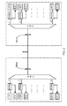
- FIG. 2 a schematic diagram of a WDM-PON system using a self-seeding laser is illustrated.
- a multi-longitudinal-mode optical signal emitted by a self-injection locking laser of a user end ONU is filtered by an AWG at a remote node (Remote Node, RN)
- RN remote node
- only an optical signal of a corresponding wavelength may permeate the RN-AWG and enter a partial reflection mirror (Partial Reflection Mirror, PRM) disposed at a trunk fiber.
- PRM Partial Reflection Mirror
- the self-injection locking laser and the partial reflection mirror cooperatively form an external cavity self-seeding laser, and a laser resonance oscillation cavity is formed in between and outputs a stable optical signal.
- the uplink data of the ONU may further pass through the trunk fiber, and be demultiplexed by an AWG at a central office (Central Office, CO) and then output to a corresponding receiver (Rx) of an OLT.
- a downlink optical signal emitted by the OLT is demultiplexed by the RN-AWG, and then output to a receiver of a corresponding ONU.
- each channel of the AWG is used as an intra-cavity filter of the self-seeding laser, which requires that a filtering curve of the AWG channel has narrow bandwidth and has a maximum transmissivity at a central wavelength of the channel.
- the AWG functions as demultiplexing, which requires that the AWG channel has wide bandwidth and a transmission curve is flat in the channel. Due to the two contradictive requirements, the optical transceiver and the WDM-PON system that are based on the self-seeding laser have limited performances, and fail to meet the demand in practical application.
- Embodiments of the present invention provide a self-injection optical transceiver module and a WDM-PON system based on the optical transceiver module, so as to solve the problem of poor performance in the existing techniques.
- a self-injection optical transceiver mod includes a gain medium, a photoelectric converter, at least one arrayed waveguide grating AWG, and a partial reflection mirror, where the at least one AWG includes two common ports and a plurality of branch ports.
- One of the common ports functions as a signal sending port
- the other one of the common ports functions as a signal receiving port.
- Bandwidth of the signal sending port is less than that of the signal receiving port.
- the gain medium and the photoelectric converter are connected to one of the branch ports of the AWG.
- the AWG and the partial reflection mirror are configured to cooperatively perform wavelength self-injection locking on an optical signal provided by the gain medium, and output the optical signal through the signal sending port.
- the AWG is further configured to demultiplex an optical signal received by the signal receiving port to a corresponding branch port.
- a wavelength division multiplexing passive optical network system includes a self-injection optical transceiver module at a central office and a self-injection optical transceiver module at a user end, where the self-injection optical transceiver module at the central office and the self-injection optical transceiver module at the user end each include the above-mentioned self-injection optical transceiver module.
- a wavelength division multiplexing passive optical network system includes an optical line terminal located at a central office and a plurality of optical network units located at a user end, where the optical line terminal is connected to the optical network units through fibers.
- the optical line terminal includes a plurality of self-injection optical transceiver modules at the central office, where the self-injection optical transceiver modules at the central office share a common arrayed waveguide grating AWG at the central office.
- the AWG at the central office includes two common ports and a plurality of branch ports. Each self-injection optical transceiver module at the central office is correspondingly connected to one of the branch ports of the AWG at the central office respectively.
- One of the common ports of the AWG at the central office functions as a signal sending port at the central office
- the other one of the common ports of the AWG at the central office functions as a signal receiving port at the central office.
- Bandwidth of the signal sending port at the central office is less than that of the signal receiving port at the central office.
- the AWG of the self-injection optical transceiver module provided in embodiments of the present invention has two common ports, that is, the signal sending port and the signal receiving port, and the bandwidth of the signal sending port is less than that of the signal receiving port, so that the AWG may use different common ports respectively in sending and receiving an optical signal.
- the bandwidth of the signal sending port is narrow, a transmission peak of the signal sending port is identical to a central wavelength of an AWG channel, thereby effectively improving the performance of signal transmission.
- Channel bandwidth corresponding to the signal receiving port is wide, which may ensure that the quality of a signal received after demultiplexing is good. Therefore, compared with the prior art, the performance of the self-injection optical transceiver module and the WDM-PON system provided in embodiments of the present invention is improved.
- an AWG undertakes the functions of forming an intra-cavity filter for a transmitting end and a demultiplexer for a receiving end. Since the two functions have contradictive requirements on bandwidth, for the applicability to sending and receiving an optical signal at the same time, in the industry, a compromise should be made when selecting a bandwidth of a common port of the AWG, which causes poor performance of an optical transceiver module and a WDM-PON system based on a self-seeding laser at present.
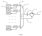
- an embodiment of the present invention provides a self-injection optical transceiver module, where the optical transceiver module may include a transmitter and a receiver.
- the transmitter of the optical transceiver module includes a gain medium 11, an AWG 2, and a partial reflection mirror 12.
- the AWG 2 includes a branch port 22 connected to the gain medium 11, and a signal sending port 13 connected to the partial reflection mirror 12, where a wavelength channel of the branch port 22 is corresponding to a working wavelength of the transmitter, and the signal sending port 13 is configured to send an optical signal provided by the gain medium 11 to a trunk fiber 4.
- the receiver of the optical transceiver module includes a photoelectric converter 21 and an AWG 2.
- the AWG 2 is connected to the photoelectric converter 21 through the branch port 22; and the AWG 2 may be further disposed with a signal receiving port 23 configured to receive the optical signal from the trunk fiber 4.
- the transmitter and the receiver may share the AWG 2, for example, the AWG 2 may function as a filter of the transmitter in one aspect, configured to limit a wavelength of the optical signal transmitted by the transmitter to the working wavelength of the optical transceiver module, and may function as a demultiplexer of the receiver in another aspect, configured to demultiplex the optical signal received from the trunk fiber 4 to the corresponding branch port 22, so that the optical signal is received by the photoelectric converter 21.
- the AWG 2 may function as a filter of the transmitter in one aspect, configured to limit a wavelength of the optical signal transmitted by the transmitter to the working wavelength of the optical transceiver module, and may function as a demultiplexer of the receiver in another aspect, configured to demultiplex the optical signal received from the trunk fiber 4 to the corresponding branch port 22, so that the optical signal is received by the photoelectric converter 21.
- the optical transceiver module may further include a circulator 1.
- the signal sending port 13 and the signal receiving port 23 of the AWG 2 may be connected to the trunk fiber 4 through the circulator 1.
- the partial reflection mirror 12 may be disposed between the signal sending port 13 and the circulator 1.
- the circulator 1 may provide the optical signal from the signal sending port 13 to the trunk fiber 4, and provide the optical signal from the trunk fiber 4 to the signal receiving port 23.
- the circulator may be replaced by a wavelength division multiplexer.
- bandwidth of the signal sending port 13 is less than that of the signal receiving port 23, for example, 3dB bandwidth of the signal sending port 13 may be relatively narrow, so as to improve the filtering function for the transmitter of the optical transceiver module, and 3dB bandwidth of the signal receiving port 23 may be relatively wide, so as to improve the demultiplexing function for the receiver of the optical transceiver module.
- the self-injection optical transceiver module may send a downlink optical signal to a user end ONU through the trunk fiber 4 connected to the self-injection optical transceiver module, and receive an uplink optical signal from the user end ONU.
- two types of common ports are disposed in the AWG 2 of the self-injection optical transceiver module, namely, the signal sending port 13 and the signal receiving port 23.
- the signal sending port 13 is configured to send the downlink optical signal
- the signal receiving port 23 is configured to receive the uplink optical signal.
- the signal sending port 13 may be designed such that 3dB bandwidth of the signal sending port 13 is relative narrow and the signal sending port 13 have a maximum transmissivity at the central wavelength of the channel.
- the signal sending port 13 may be a Gaussian-type port having narrow 3dB bandwidth.
- the signal receiving port 23 configured to receive the uplink optical signal
- t the signal receiving port 23 may be designed such that 3dB bandwidth of the signal receiving port 23 is relatively wide, that is, the pass band wavelength of the signal receiving port 23 has a small transmissivity variation in a wide range, so that the self-injection optical transceiver module has a good receiving performance when receiving the uplink optical signal.
- the signal receiving port 23 may be a flat-type port having wide 3dB bandwidth. It should be understood that, the "wide 3dB bandwidth" and the "narrow 3dB bandwidth” are relative terms, and specific bandwidth may be configured according to the number of the wavelength channels of the AWG 2.
- the 3dB bandwidth of the signal sending port 13 is at least less than the 3dB bandwidth of the signal receiving port 23.
- a transmitter may include the gain medium 11, the AWG 2, and the partial reflection mirror 12.
- a branch port 22 connected to the gain medium 11 and a signal sending port 13 connected to the partial reflection mirror 12 are disposed in the AWG 2.
- the signal sending port 13 is further connected to a circulator 1 or a wavelength division multiplexer, and the circulator 1 or the wavelength division multiplexer is further connected to a trunk fiber 4.
- ASE Anamplified Spontaneous Emission, amplified spontaneous emission
- the ASE optical signal passes through a wavelength channel of the AWG 2, optical signals beyond the corresponding wavelength channel are filtered out or lost, and therefore, only an optical signal with wavelength within a pass band range determined by the branch port 22 and the signal sending port 13 of the AWG 2 can pass through the AWG 2. Then, the optical signal is transmitted to the partial reflection mirror 12 through the signal sending port 13, where a part of the optical signal is reflected back by the partial reflection mirror 12, injected into the gain medium 11, and amplified again. Such a round trip is performed for multiple times.
- the round trips of the optical signal between the gain medium 11 and the partial reflection mirror 12 for multiple times result in resonance oscillation amplification, and finally enable the optical signal generated by the transmitter to work at a transmission peak wavelength determined by the signal sending port 13 and the branch port 22, thereby forming a downlink optical signal that may be sent through the signal sending port 13.
- the downlink optical signal After passing through the signal sending port 13, the downlink optical signal is further sent to the trunk fiber 4 through the circulator 1 or the wavelength division multiplexer, and is transmitted by the trunk fiber 4 to a corresponding ONU at the user end.
- the signal sending port 13 functions to form an intra-cavity filter in the transmitter, therefore, bandwidth design and optimization of the signal sending port 13 may be performed separately to enable the desired bandwidth to be relatively narrow, and a transmission peak is identical to a central wavelength of the corresponding AWG channel, thereby effectively improving the performance of signal transmission.
- a receiver may include the photoelectric converter 21 and an AWG 2.
- the branch port 22 connected to the photoelectric converter 21 and a signal receiving port 23 are further disposed in the AWG 2.
- the signal receiving port 23 is connected to a circulator 1 or a wavelength division multiplexer, and the circulator 1 or the wavelength division multiplexer is further connected to the trunk fiber 4.
- an uplink optical signal is transmitted from the trunk fiber 4 to the circulator 1 or the wavelength division multiplexer, and then is further conducted to the signal receiving port 23 by the circulator 1 or the wavelength division multiplexer.
- the AWG 2 demultiplexes the uplink optical signal to the branch port 22 corresponding to the receiver, and the optical signal is transmitted to the photoelectric converter 21 in the receiver through the branch port 22 of the AWG 2.
- the photoelectric converter 21 may be a photoelectric diode.
- the uplink optical signal transmitted by the trunk fiber 4 may pass through the circulator 1, enter the flat-type signal receiving port 23 with 3dB bandwidth that is relatively wide, be demultiplexed by the AWG 2 to the corresponding branch port 22, and then provided by a wavelength division multiplexer to the photoelectric converter 21.
- the signal receiving port 23 is configured separately and independent from the signal sending port 12, the channel bandwidth corresponding to the signal receiving port 23 may be designed to be relatively wide and a transmission curve of the signal receiving port 23 is flat, so that the quality of the signal received after demultiplexing is good.
- two types of common ports are configured in the AWG in the self-injection optical transceiver module, namely, a signal sending port with 3dB bandwidth that is relatively narrow and a signal receiving port with 3dB bandwidth that is relatively wide, so that the AWG may use different common ports for optical signal transmission and reception respectively.
- the 3dB bandwidth of the signal sending port is designed to be relatively narrow
- the 3dB bandwidth of the signal receiving port is designed to be relatively wide
- the quality of the optical signal reception and transmission of the self-injection optical transceiver module is ensured.
- bandwidth optimization designs can be seperately performed on the signal receiving port and the signal sending port of the self-injection optical transceiver module, which significantly improves the performance of the self-injection optical transceiver module.
- the gain medium in the receiver may specifically include an IL FP-LD (Injection-Locked Fabry-Perot Laser Diode, injection-locked Fabry-Perot laser diode) or an RSOA (Reflective Semiconductor Optical Amplifier, reflective semiconductor optical amplifier).
- IL FP-LD Injection-Locked Fabry-Perot Laser Diode, injection-locked Fabry-Perot laser diode
- RSOA Reflective Semiconductor Optical Amplifier, reflective semiconductor optical amplifier
- the partial reflection mirror may further be a Faraday rotator mirror.
- a 45° one-way Faraday cup may be added before the partial reflection mirror, to form a faraday rotator mirror (FRM, Faraday Rotator Mirror).
- FRM Faraday Rotator Mirror
- a polarization direction of the optical signal is rotated by 90°.
- a TE mode of the optical signal emitted from a laser transceiver becomes a TM mode after being reflected back by the FRM
- the emitted TM mode of the optical signal becomes the TE mode after being reflected back by the TE. Therefore, the correlation of polarization gain in a self-injection laser transceiver is diminished, which improves the ability of the self-injection fiber laser transceiver in resisting random polarization interference in the embodiment of the present invention.
- the self-injection optical transceiver module provided in the embodiment of the present invention may be further applied in user end ONUs in the WDM-PON system, and a specific structure of the self-injection optical transceiver module is similar to that of the self-injection optical transceiver module at the central office. The difference only lies in that, for the self-injection optical transceiver module in the user end ONU, the receiver is configured to receive the downlink optical signal, and the transmitter is configured to send the uplink optical signal.
- the gain medium of the self-injection optical transceiver module at the central office has a gain amplification function for a downlink wave band
- the gain medium of the self-injection optical transceiver module at the user end has a gain amplification function for an uplink wave band.
- the wavelength division multiplexer has the functions of multiplexing the uplink wave band and demultiplexing the downlink wave band.
- a waveguide at a signal sending end of the AWG 2 is designed to have an inverted conical structure, that is, a waveguide close to a Roland circle of the AWG 2 is narrow, and a waveguide at an output end is wide, so that the 3dB bandwidth of the signal sending port is narrow.
- a waveguide close to a Roland circle of the AWG 2 is narrow, and a waveguide at an output end is wide, so that the 3dB bandwidth of the signal sending port is narrow.
- the bandwidth of the signal sending port 13 less than that of the signal receiving port 23 may be achieved through some other manners, for example, the 3dB bandwidth of the signal receiving port may be increased by disposing a conical waveguide structure, a Mach-Zehnder interferometer structure, or a multimode coupler at the signal receiving port 23, or by cascading multiple AWGs.
- the signal sending port and the signal receiving port having different bandwidths may also be achieved by use of two AWGs with different 3dB bandwidth. That is, the two AWGs with different 3dB bandwidth respectively function as a signal receiving AWG and a signal sending AWG.
- a common port of the AWG with 3dB bandwidth that is relatively narrow functions as the signal receiving port, and the AWG is referred to as the signal receiving AWG.
- a common port of the AWG with 3dB bandwidth that is relatively wide functions as the signal sending port, and the AWG is referred to as the signal sending AWG.
- the signal sending port and the signal receiving port having different bandwidths may also be achieved by use of two AWGs with the same 3dB bandwidth and one periodic filter with narrow bandwidth.
- a common port of a signal sending AWG may be connected to the periodic filter with narrow 3dB bandwidth, for example, a Fabry-Perot etalon, so that the optical signal sent by the signal sending AWG has 3dB bandwidth that is relatively narrow.
- the other AWG may function as a signal receiving AWG, and 3dB bandwidth of the signal receiving AWG is greater than that of the signal sending AWG.
- an embodiment of the present invention further provides a WDM-PON system.
- the WDM-PON system may include self-injection optical transceiver modules at a central office and self-injection optical transceiver modules at user ends.
- the optical transceiver modules provided in the above embodiments may be used as the self-injection optical transceiver modules at the central office and the self-injection optical transceiver modules at the user ends.
- the self-injection optical transceiver modules at the central office may be disposed at an OLT, and may function as optical transceiver modules of the OLT.
- the self-injection optical transceiver modules at the user ends may be separately disposed at user ends, and function as optical transceiver modules of the ONUs.
- Each optical transceiver module of the OLT corresponds to the optical transceiver module of a respective ONU, and the operation wavelength of the optical transceiver module of the OLT is the same as that of the corresponding one of the optical transceiver module of the ONU.
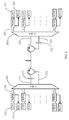
- the self-injection optical transceiver module at the central office may include an AWG 102 and a partial reflection mirror 112.
- the AWG 102 includes multiple branch ports 122 and two common ports, the two common ports are respectively configured as a signal receiving port 123 and a signal sending port 113.
- Each of the branch port 122 is connected to a gain medium 111 and a photoelectric converter 121 through a wavelength division multiplexer.
- the signal sending port 113 has a Gaussian-type or semi-Gaussian-type filtering curve, and has 3dB bandwidth that is relatively narrow.
- the signal receiving port 123 has a flat-type filtering curve, and has 3dB bandwidth that is relatively wide.
- the self-injection optical transceiver module at the user end includes an AWG 202 and a partial reflection mirror 212.
- the AWG 102 includes multiple branch ports and two common ports, and the two common ports are respectively configured as a signal sending port 213 and a signal receiving port 223.
- Each of the branch ports 222 is connected to a gain medium 211 and a photoelectric converter 221 through a wavelength division multiplexer.
- the signal sending port 213 has a Gaussian-type or semi-Gaussian-type filtering curve, and has 3dB bandwidth that is relatively narrow.
- the signal receiving port 223 has a flat filtering curve, and has 3dB bandwidth that is relatively wide.
- each of the branch ports 122 is connected to a gain medium 111 and a photoelectric converter 121 through a wavelength division multiplexer, that is, the branch ports of the AWG 102 are correspondingly connected to the gain mediums 111 and the photoelectric converters 121 one by one.
- a first gain medium and a first photoelectric converter are connected to a first branch port
- a second gain medium and a second photoelectric converter are connected to a second branch port
- the connection of other branch ports may be deduced by analogy.
- a location of the signal sending port 113 of the self-injection optical transceiver module 100 at the central office on a Roland circle of the AWG 102 is corresponding to a location of the signal receiving port 223 of the self-injection optical transceiver module 200 at the user end on the Roland circle of the AWG 202.
- a location of the signal receiving port 123 of the self-injection optical transceiver module 100 at the central office on the Roland circle of the AWG 102 is corresponding to a location of the signal sending port 213 of the self-injection optical transceiver module 200 at the user end on the Roland circle of the AWG 202.
- a downlink optical signal generated by the self-injection optical transceiver module 100 at the central office is sent from the signal sending port 113 to a trunk fiber via the partial reflection mirror 112, enters the signal receiving port 223 of the self-injection optical transceiver module 200 at the user end, and is demultiplexed by the AWG 202 to a corresponding branch port 222, and then is provided to and received by a photoelectric converter 221 of the corresponding optical transceiver module at the user end.
- the partial reflection mirror 212 is configured in the self-injection optical transceiver module 200 at the user end.
- An uplink optical signal generated by the self-injection optical transceiver module at the user end is transmitted from the signal sending port 213 to the trunk fiber via the partial reflection mirror 212, enters the signal receiving port 123 of the self-injection optical transceiver module 100 at the central office, and is demultiplexed by the AWG 102 to a corresponding branch port 122, and then is provided to and received by a photoelectric converter 121 of the corresponding optical transceiver module at the central office.
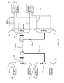
- FIG. 5 is a schematic structural diagram of another embodiment of a WDM-PON system based on a self-injection optical transceiver module of the present invention.
- an AWG employed in the self-injection optical transceiver module is a non-wavelength 0-hop AWG.
- both a self-injection optical transceiver module at a central office and a self-injection optical transceiver module at a user end include 32 receivers and transmitters, a location of a signal sending port 313 of an AWG 302 on a Roland circle of the AWG 302 corresponds to a location of a signal sending port 413 of an AWG 402 on a Roland circle of the AWG 402, and a location of a signal receiving port 323 on a Roland circle of the AWG 302 corresponds to a signal sending port 423 on the Roland circle of the AWG 402.
- the signal receiving port 313 and the signal sending port 312 of the AWG 302 are spaced by a wavelength channel of the AWG 302, and the signal receiving port 413 and the signal sending port 412 of the AWG 402 are also spaced by a channel of the AWG 402; locations of the second to 33 rd branch ports of the AWG 302 on the Roland circle of the AWG 302 are respectively corresponding to the first to 32 nd branch ports of the AWG 402 on the Roland circle of the AWG 402.
- the first port of the AWG 302 is a previous port adjacent to the second port, and the 34 th port is a next port adjacent to the 33 rd port.
- the downlink optical signal may not be demultiplexed to a k th branch port (that is, a k th user) of the AWG 402.
- fiber connections of the AWG 302 of the self-injection optical transceiver module at the central office can be modified. As for a specific fiber connection manner, reference may be made to FIG. 5 .
- a possible value of channel spacing between the signal receiving port and the signal sending port of the AWG 302 may be 1, 2, 3, or the like.
- the channel spacing between the signal receiving port and the signal sending port of the AWG302 is m.
- the k th gain medium in the self-injection optical transceiver module at the central office only needs to be connected to the (k+2m) th branch port in the AWG 302.
- the location of the m th port of the AWG 302 of the self-injection optical transceiver module at the central office on the Roland circle of the AWG 302 is corresponding to the location of the first port of the AWG 402 in the self-injection optical transceiver module at the user end on the Roland circle of the AWG 402.
- the branch ports of the AWG 402 and the gain media in the optical transceiver module at the user end only need to be connected one by one correspondingly, as shown in FIG. 5 .
- the downlink optical signal from the self-injection optical transceiver module at the central office enters the trunk fiber through the transmitting port 312 of the AWG 302, and then enters the signal receiving port 423 of the AWG 402 in the self-injection optical transceiver module at the user end.
- the AWG employed in the self-injection optical transceiver module is a non-wavelength 0-hop AWG, that is, the channel of the signal sending port of the AWG 302 is different from that of the signal receiving port of the AWG 402.
- the channel spacing is 1; in this case, a downlink optical signal sent by the (k+2)th branch port of the AWG 302 may be demultiplexed to the kth branch port of the AWG 402 in the self-injection optical transceiver module at the user end. Therefore, in order to ensure that the self-injection optical transceiver module in the embodiment of the present invention can work normally, the kth gain medium in the self-injection optical transceiver module at the central office is further connected to the (k+2)th branch port of the AWG 302.
- the first gain medium of the self-injection optical transceiver module at the central office is connected to the third branch port of the AWG 302, the second gain medium is connected to the fourth branch port of the AWG 302, and connection of the remaining gain media and branch ports of the AWG 302 can be deduced by analogy.
- the self-injection optical transceiver module at the user end may use a 32-channel AWG to form 32 receivers and transmitters, however, in the self-injection optical transceiver module at the central office, as the 32nd gain medium needs to be connected to the 34th branch port of the AWG 302, the AWG 302 of the self-injection optical transceiver module at the central office needs to be disposed with at least 34 branch ports.
- a 40-channel AWG may be used.
- an AWG used by a WDM-PON system may also be a wavelength 0-hop AWG.
- the embodiment shown in FIG. 6 is similar to the embodiment corresponding to FIG. 5 .
- the difference lies in that the AWG of a self-injection optical transceiver module in the embodiment shown in FIG. 6 is wavelength 0-hop AWG.
- the wavelength 0-hop AWG has N branch ports in total, as the ports of the wavelength 0-hop AWG has a circulating characteristic, that is, a k th wavelength and a (k+N) th wavelength may occur at the same port, a wavelength next to that of an N th channel of the AWG may reoccur at a first channel, and then the circulation continues.
- a self-injection optical transceiver module at a central office and a self-injection optical transceiver module at a user end employ the same wavelength 0-hop AWG, and two common ports of the AWG are two adjacent channels, in order to send a downlink optical signal provided by a first gain medium in the self-injection optical transceiver module at the central office to a photoelectric converter connected to a first branch port in an AWG 602, a first gain medium 511 in the self-injection optical transceiver module at the central office may be connected to a second branch port in an AWG 502. Connection manners of other gain mediums are similar to that of the first gain medium, except the last gain medium of the self-injection optical transceiver module at the central office.
- a second gain medium needs to be connected to a third branch port in the AWG 502, and the rest may be deduced by analogy.
- the last gain medium in the self-injection optical transceiver module at the central office needs to be connected to the first branch port in the AWG 502.
- the photoelectric converters 621 in the self-injection optical transceiver modules at the user end respectively correspond to the gain mediums 511 of self-injection optical fiber laser transceivers 500 at the central office.
- a second photoelectric converter in the self-injection optical transceiver module at the central office is connected to the first branch port of the AWG 502, so as to receive an uplink optical signal sent by the first gain medium in the self-injection optical transceiver module at the user end.
- Connection manners of other photoelectric converters are similar to that of the second photoelectric converter, except the first photoelectric converter of the self-injection optical transceiver module at the central office.
- a third photoelectric converter of the self-injection optical transceiver module at the central office needs to be connected to the second branch port in the AWG 502, and the rest may be deduced by analogy.
- the first photoelectric converter in the self-injection optical transceiver module at the central office needs to be connected to a last branch port in the AWG 502.
- two AWGs with different 3dB bandwidth may be combined, where a common port of the AWG with 3dB bandwidth that is relatively narrow serves as a signal sending port, and a common port with 3dB bandwidth that is relatively wide serves as a signal receiving port.
- a partial reflector is connected to the signal sending port of the AWG with 3dB bandwidth that is relatively narrow, and a received signal is connected to the signal receiving port of the AWG with 3dB bandwidth that is relatively wide.
- a self-injection optical transceiver module at a central office may include an AWG 31 and an AWG 41, and the two AWGs have different 3dB bandwidth respectively.
- a self-injection optical transceiver module at a user end may use an AWG 51 having two common ports with different 3dB bandwidth.
- the AWG 31 includes a signal sending port 33 with 3dB bandwidth that is relatively narrow, and the signal sending port 33 is configured to send a downlink optical signal.
- the AWG 41 includes a signal receiving port 43 with 3dB bandwidth that is relatively wide, and the signal receiving port 43 is configured to receive an uplink optical signal.
- the AWG 51 includes a signal sending port 53 with 3dB bandwidth that is relatively narrow and a signal receiving port 56 with 3dB bandwidth that is relatively wide.
- a first gain medium 32 of the self-injection optical transceiver module at the central office sends, through a first branch port 34, a downlink optical signal along the signal sending port 33 to a trunk fiber.
- the signal receiving port 56 of the AWG 51 receives the downlink optical signal, the downlink optical signal enters a first branch port 54 of the self-injection optical transceiver module at the user end, and then enters a first photoelectric converter 52.
- a first gain medium 52 of the self-injection optical transceiver module at the user end sends, through the first branch port 54, an uplink optical signal along the signal sending port 53 to the trunk fiber.
- the signal receiving port 43 of the AWG 41 receives the downlink optical signal, the signal enters a first branch port 44 of the AWG 41, and then enters the first photoelectric converter 42.
- the self-injection optical transceiver module at the central office and the self-injection optical transceiver module at the user end may be set to be formed by two AWGs.
- a self-injection optical transceiver module at a central office may include an AWG 61 and an AWG 71, and the two AWGs have different 3dB bandwidth respectively.
- a self-injection optical transceiver module at a user end may include an AWG 81 and an AWG 91, and the two AWGs have different 3dB bandwidth respectively.
- the AWG 61 includes a signal sending port 63 with 3dB bandwidth that is relatively narrow, and the signal sending port 63 is configured to send a downlink optical signal.
- the AWG 71 includes a signal receiving port 73 with 3dB bandwidth that is relatively wide, and the signal receiving port 73 is configured to receive an uplink optical signal.
- the AWG 81 includes a signal sending port 83 with 3dB bandwidth that is relatively narrow, and the signal sending port 83 is configured to send an uplink optical signal.
- the AWG 71 includes a signal receiving port 93 with 3dB bandwidth that is relatively wide, and the signal receiving port 93 is configured to receive a downlink optical signal.
- a specific operation of the self-injection optical transceiver module at the central office and the self-injection optical transceiver module at the user end is as follows.
- a first gain medium 62 of the self-injection optical transceiver module at the central office sends, through a first branch port 64, a downlink optical signal along the signal sending port 63 to a trunk fiber.
- the signal receiving port 93 of the AWG 91 receives the downlink optical signal
- the downlink optical signal enters a first branch port 94 of the AWG 91, and then enters a first photoelectric converter 92.
- a first gain medium 82 of the self-injection optical transceiver module at the user end sends, through a first branch port 84 of the AWG 81, an uplink optical signal along the signal sending port 83 to the trunk fiber.
- the signal receiving port 73 of the AWG 71 receives the downlink optical signal
- the downlink optical signal enters a first branch port 74 of the AWG 71, and then enters a first photoelectric converter 72 of the self-injection optical transceiver module at the central office.
- an uplink wave band and a downlink wave band may be an FSR (Free Spectral Range, free spectral range) wave band adjacent to the AWG, or an FSR wave band not adjacent to the AWG.
- FSR Free Spectral Range, free spectral range
- Embodiments in this specification are described in a progressive way. Each embodiment highlights the difference from other embodiments, and for the same or similar parts of the embodiments, reference may be made to each other.
- the description on the apparatus disclosed in the embodiments is simple because the apparatus is corresponding to the method disclosed in the embodiments, and reference may be made to the description in the method part.
Landscapes
- Engineering & Computer Science (AREA)
- Computer Networks & Wireless Communication (AREA)
- Signal Processing (AREA)
- Physics & Mathematics (AREA)
- Electromagnetism (AREA)
- Optical Communication System (AREA)
- Semiconductor Lasers (AREA)
Applications Claiming Priority (1)
| Application Number | Priority Date | Filing Date | Title |
|---|---|---|---|
| PCT/CN2011/073196 WO2011110126A2 (fr) | 2011-04-22 | 2011-04-22 | Module d'émission-réception optique par auto-injection et système de réseau optique passif à multiplexage par répartition en longueur d'onde |
Publications (3)
| Publication Number | Publication Date |
|---|---|
| EP2482472A2 true EP2482472A2 (fr) | 2012-08-01 |
| EP2482472A4 EP2482472A4 (fr) | 2012-11-21 |
| EP2482472B1 EP2482472B1 (fr) | 2013-09-04 |
Family
ID=44563905
Family Applications (1)
| Application Number | Title | Priority Date | Filing Date |
|---|---|---|---|
| EP11752869.5A Not-in-force EP2482472B1 (fr) | 2011-04-22 | 2011-04-22 | Module d'émission-réception optique par auto-injection et système de réseau optique passif à multiplexage par répartition en longueur d'onde |
Country Status (14)
| Country | Link |
|---|---|
| US (1) | US8971709B2 (fr) |
| EP (1) | EP2482472B1 (fr) |
| JP (1) | JP5778335B2 (fr) |
| KR (1) | KR101519939B1 (fr) |
| CN (1) | CN102388547B (fr) |
| AR (1) | AR086361A1 (fr) |
| AU (1) | AU2011226481B2 (fr) |
| CA (1) | CA2833624C (fr) |
| ES (1) | ES2436858T3 (fr) |
| PT (1) | PT2482472E (fr) |
| RU (1) | RU2562808C2 (fr) |
| SG (1) | SG194545A1 (fr) |
| TW (1) | TWI452852B (fr) |
| WO (1) | WO2011110126A2 (fr) |
Cited By (4)
| Publication number | Priority date | Publication date | Assignee | Title |
|---|---|---|---|---|
| WO2013082566A1 (fr) * | 2011-12-01 | 2013-06-06 | Huawei Technologies Co., Ltd. | Émetteur en mode rafale sans couleur à auto-ensemencement utilisant un amplificateur optique semi-conducteur réfléchissant et un laser fabry-perot verrouillé par injection |
| EP2775643A1 (fr) | 2013-03-08 | 2014-09-10 | Rigas Tehniska universitate | Réseau optique passif à multiplexage par répartition en longueur d'onde haute densité |
| EP2784960A1 (fr) * | 2013-03-27 | 2014-10-01 | Alcatel Lucent | Transmetteur optique pour réseau WDM |
| US9559802B1 (en) | 2014-09-30 | 2017-01-31 | Google Inc. | Optical network remote node for G-PON and WDM-PON |
Families Citing this family (29)
| Publication number | Priority date | Publication date | Assignee | Title |
|---|---|---|---|---|
| US8559821B2 (en) * | 2009-12-02 | 2013-10-15 | Futurewei Technologies, Inc. | Wavelength stabilization and locking for colorless dense wavelength division multiplexing transmitters |
| RU2562808C2 (ru) * | 2011-04-22 | 2015-09-10 | Хуавэй Текнолоджиз Ко., Лтд. | Устройство оптического приемопередатчика и система пассивных оптических сетей с мультиплексированием с разделением по длине волны |
| CN102204037B (zh) * | 2011-05-10 | 2013-01-02 | 华为技术有限公司 | 自注入激光器、波分复用无源光网络系统及光线路终端 |
| US9502858B2 (en) * | 2011-07-14 | 2016-11-22 | Applied Optoelectronics, Inc. | Laser array mux assembly with external reflector for providing a selected wavelength or multiplexed wavelengths |
| WO2013097185A1 (fr) * | 2011-12-30 | 2013-07-04 | 华为技术有限公司 | Multiplexeur/démultiplexeur par répartition en longueur d'onde, laser à fibre à amorçage automatique, et système de réseau optique |
| CN102742198B (zh) * | 2012-04-06 | 2016-05-25 | 华为技术有限公司 | 波分复用器及无源光网络系统 |
| CN103516434B (zh) * | 2012-06-19 | 2016-08-31 | 上海贝尔股份有限公司 | 光发射机 |
| FR2992482A1 (fr) * | 2012-06-22 | 2013-12-27 | France Telecom | Dispositif lumineux reflechissant destine a un reseau d'acces optique wdm pon comprenant une source lumineuse avec un milieu de gain optique |
| WO2014000298A1 (fr) * | 2012-06-30 | 2014-01-03 | 华为技术有限公司 | Laser à auto-injection et réseau optique passif |
| US8970945B2 (en) | 2012-07-24 | 2015-03-03 | University of Zagreb, Faculty of Electrical Engineering and Computing | Modulation averaging reflectors |
| JP6096296B2 (ja) * | 2012-07-30 | 2017-03-15 | オプリンク コミュニケーションズ エルエルシー | 外部キャビティファブリペローレーザ |
| US9214790B2 (en) * | 2012-10-03 | 2015-12-15 | Applied Optoelectronics, Inc. | Filtered laser array assembly with external optical modulation and WDM optical system including same |
| FR3000855A1 (fr) * | 2013-01-10 | 2014-07-11 | France Telecom | Procede et dispositif reflechissant pour realiser la fonction receptrice d'un reseau d'acces optique utilisant un multiplexage en longueur d'onde |
| US9197352B2 (en) * | 2013-03-11 | 2015-11-24 | Google Inc. | Increasing the capacity of a WDM-PON with wavelength reuse |
| JP6531314B2 (ja) * | 2014-06-25 | 2019-06-19 | 国立大学法人 東京大学 | 光送受信装置及び通信システム |
| US9806816B2 (en) | 2014-10-10 | 2017-10-31 | Futurewei Technologies, Inc. | Re-modulation crosstalk and intensity noise cancellation in wavelength-division multiplexing (WDM) passive optical networks (PONs) |
| US9634877B2 (en) * | 2015-07-01 | 2017-04-25 | Sunrise Micro Devices, Inc. | Trim for dual-port frequency modulation |
| TWI566918B (zh) | 2015-07-29 | 2017-01-21 | 財團法人工業技術研究院 | 立體列印系統 |
| US9729950B2 (en) | 2015-11-25 | 2017-08-08 | Google Inc. | Upgrading PON systems using a multi-cycle field AWG |
| CN108604932B (zh) * | 2016-01-28 | 2020-08-07 | 华为技术有限公司 | 波长可调谐的光发射装置 |
| CN108476065B (zh) | 2016-02-02 | 2020-06-16 | 华为技术有限公司 | 一种光反射复用芯片、激光发射芯片以及光发射机 |
| US10069562B2 (en) * | 2016-10-11 | 2018-09-04 | X Development Llc | Optical circulator for free space optical communication |
| WO2018068206A1 (fr) * | 2016-10-11 | 2018-04-19 | 华为技术有限公司 | Ensemble émetteur-récepteur de lumière |
| US10374742B2 (en) * | 2017-02-15 | 2019-08-06 | Finisar Corporation | Bidirectional optical communication with minimal guard band |
| CN106817323B (zh) * | 2017-03-06 | 2023-08-22 | 南京曦光信息科技有限公司 | 一种可片上集成的物理层组播光交换节点装置及网络 |
| US11102426B1 (en) * | 2018-05-18 | 2021-08-24 | Lockheed Martin Corporation | Photonic integrated circuit for heterodyne imaging |
| KR20200059356A (ko) * | 2018-11-20 | 2020-05-29 | 주식회사 오이솔루션 | 멀티채널 양방향 광통신 모듈 |
| WO2022011240A1 (fr) | 2020-07-10 | 2022-01-13 | Raytheon Company | Récepteur et système de transport et de démodulation de signaux optiques complexes |
| US11909444B2 (en) * | 2022-02-11 | 2024-02-20 | Raytheon Company | Method for an all fiber optic, polarization insensitive, etalon based optical receiver for coherent signals |
Citations (4)
| Publication number | Priority date | Publication date | Assignee | Title |
|---|---|---|---|---|
| US20040067059A1 (en) * | 2002-10-01 | 2004-04-08 | Jae-Won Song | Dense wavelength division multiplexing-passive optical network system utilizing self-injection locking of Fabry-Perot laser diodes |
| US20040179843A1 (en) * | 2003-03-10 | 2004-09-16 | Dae-Kwang Jung | Wavelength division multiplexing light source apparatus using semiconductor optical amplifier |
| US20050135449A1 (en) * | 2003-12-19 | 2005-06-23 | Sorin Wayne V. | Integration of laser sources and detectors for a passive optical network |
| US20080187314A1 (en) * | 2007-02-06 | 2008-08-07 | Korea Advanced Of Science And Technology | Reflective semiconductor optical amplifier-based optical access network system having improved transmission quality |
Family Cites Families (42)
| Publication number | Priority date | Publication date | Assignee | Title |
|---|---|---|---|---|
| US5857048A (en) * | 1996-09-11 | 1999-01-05 | Lucent Technologies, Inc. | Fourier-plane photonics package |
| JP4507032B2 (ja) * | 2000-02-16 | 2010-07-21 | Kddi株式会社 | 双方向波長多重光通信システム |
| JP3890190B2 (ja) * | 2000-11-16 | 2007-03-07 | 日本電気株式会社 | アレイ導波路格子および導波路素子 |
| JP2002341158A (ja) * | 2001-05-14 | 2002-11-27 | Nippon Telegr & Teleph Corp <Ntt> | アレイ導波路格子型光波長合分波器 |
| KR100630049B1 (ko) * | 2002-03-21 | 2006-09-27 | 삼성전자주식회사 | 파장분할다중 방식의 수동형 광네트웍 시스템 |
| JP2003283438A (ja) * | 2002-03-22 | 2003-10-03 | Nec Corp | 光伝送装置および光伝送方法 |
| US6882778B2 (en) * | 2002-04-15 | 2005-04-19 | Jds Uniphase Corporation | Chromatic dispersion compensation in waveguide arrays |
| KR100515259B1 (ko) * | 2002-05-03 | 2005-09-15 | 한국과학기술원 | 파장 가변 광원 구현 방법 및 장치와 이 광원을 이용한 파장분할 다중방식 광전송 장치 |
| US7254332B2 (en) * | 2002-08-06 | 2007-08-07 | Jun-Kook Choi | Wavelength division multiplexing passive optical network system |
| KR100480276B1 (ko) * | 2003-05-02 | 2005-04-07 | 삼성전자주식회사 | 양방향 광회선 분배 장치 |
| WO2005013439A2 (fr) * | 2003-07-03 | 2005-02-10 | Pd-Ld, Inc. | Utilisation de reseaux de bragg epais pour conditionnement des caracteristiques d'emission laser |
| US7530103B2 (en) * | 2003-08-07 | 2009-05-05 | Microsoft Corporation | Projection of trustworthiness from a trusted environment to an untrusted environment |
| KR100605899B1 (ko) * | 2004-01-09 | 2006-08-02 | 삼성전자주식회사 | 파장 주입 방식을 사용한 파장분할 다중방식 자기치유수동형 광가입자망 |
| JP4713837B2 (ja) * | 2004-02-10 | 2011-06-29 | 株式会社日立製作所 | 光分岐挿入多重化装置 |
| KR100608946B1 (ko) * | 2004-10-20 | 2006-08-03 | 광주과학기술원 | 자체잠김된 페브리-페롯 레이저 다이오드를 이용한 파장분할다중 방식의 수동형 광통신망과, 이에 사용되는 지역 기지국 및 그 제어 방법 |
| US7295738B2 (en) * | 2004-12-13 | 2007-11-13 | General Dynamics Advanced Information Systems, Inc. | System and method for performing dispersion compensation |
| US7738167B2 (en) * | 2005-12-09 | 2010-06-15 | Electronics And Telecommunications Research Institute | Reflective semiconductor optical amplifier (RSOA), RSOA module having the same, and passive optical network using the same |
| KR100819034B1 (ko) * | 2006-05-11 | 2008-04-03 | 한국전자통신연구원 | 반사형 반도체 광증폭기 기반 수동형 광가입자망 |
| KR100786040B1 (ko) * | 2006-05-19 | 2007-12-17 | 한국과학기술원 | 높은 스펙트럼 효율을 구비한 전송 포맷을 이용하여 고속광신호 전송이 가능한 파장 분할 다중방식 수동형 광가입자망 |
| JP5193199B2 (ja) * | 2006-07-20 | 2013-05-08 | フランス・テレコム | 増幅光信号のリモート変調を用いた長距離パッシブ光ネットワーク |
| US8073331B1 (en) * | 2006-12-06 | 2011-12-06 | Mazed Mohammad A | Dynamic intelligent bidirectional optical and wireless access communication system |
| US8260140B2 (en) * | 2007-01-09 | 2012-09-04 | Nec Laboratories America, Inc. | WDM passive optical network with parallel signal detection for video and data delivery |
| KR100860548B1 (ko) * | 2007-05-09 | 2008-09-26 | 광주과학기술원 | 자체 잠김을 이용한 파장 추적 시스템, 이를 포함하는파장분할다중 방식의 수동형 광통신 시스템 및 파장 추적방법 |
| KR100889861B1 (ko) * | 2007-05-09 | 2009-03-24 | 광주과학기술원 | 자체 잠김을 이용한 파장분할다중 방식의 수동형 광통신시스템, 이에 사용되는 중앙 기지국 및 데이터 전송 방법 |
| JP5022795B2 (ja) * | 2007-07-09 | 2012-09-12 | 株式会社東芝 | 半導体受光素子およびその製造方法 |
| TWI368809B (en) * | 2008-07-08 | 2012-07-21 | Ind Tech Res Inst | Laser source based on fabry-perot laser diodes and seeding method using the same |
| CN101426154B (zh) | 2008-12-10 | 2011-07-20 | 张哲民 | 一种可用作wdm-pon光源的外腔激光器 |
| CN101557540B (zh) * | 2009-04-30 | 2012-05-23 | 上海大学 | 自注入波分复用无源光网络实现波长重用的系统和方法 |
| US8971721B2 (en) * | 2009-05-20 | 2015-03-03 | Telefonaktiebolaget L M Ericsson (Publ) | Method and system for bidirectional optical communication |
| KR101250441B1 (ko) * | 2009-06-16 | 2013-04-08 | 한국전자통신연구원 | 파장분할다중 방식의 수동형 광통신망 장치 |
| EP2452452A1 (fr) * | 2009-07-06 | 2012-05-16 | Telefonaktiebolaget L M Ericsson (PUBL) | Perfectionnements de réseaux optiques réfléchissants |
| US8417118B2 (en) * | 2009-08-14 | 2013-04-09 | Futurewei Technologies, Inc. | Colorless dense wavelength division multiplexing transmitters |
| US8538262B2 (en) * | 2009-09-14 | 2013-09-17 | Lg-Ericsson Co., Ltd. | Color free WDM PON based on broadband optical transmitters |
| US8559821B2 (en) * | 2009-12-02 | 2013-10-15 | Futurewei Technologies, Inc. | Wavelength stabilization and locking for colorless dense wavelength division multiplexing transmitters |
| US8463088B1 (en) * | 2010-09-16 | 2013-06-11 | Kotura, Inc. | Multi-channel optical device |
| US8437637B2 (en) * | 2010-11-29 | 2013-05-07 | The Chinese University Of Hong Kong | Methods and systems for multicast control |
| US8606107B2 (en) * | 2010-12-03 | 2013-12-10 | Futurewei Technologies, Inc. | Colorless dense wavelength division multiplexing transmitters |
| RU2562808C2 (ru) * | 2011-04-22 | 2015-09-10 | Хуавэй Текнолоджиз Ко., Лтд. | Устройство оптического приемопередатчика и система пассивных оптических сетей с мультиплексированием с разделением по длине волны |
| CN102204037B (zh) * | 2011-05-10 | 2013-01-02 | 华为技术有限公司 | 自注入激光器、波分复用无源光网络系统及光线路终端 |
| US8855492B2 (en) * | 2012-01-18 | 2014-10-07 | Telefonaktiebolaget Lm Ericsson (Publ) | Selectable multiple-wavelength access for optical network units in arrayed waveguide based wavelength division multiplexing passive optical network |
| US8849119B2 (en) * | 2012-02-09 | 2014-09-30 | Electronics And Telecommunications Research Institute | Wavelength-shifted bidirectional wavelength division multiplexing optical network |
| US20140016938A1 (en) * | 2012-07-11 | 2014-01-16 | Adtran, Inc. | Temperature adjustable channel transmitter system including an injection-locked fabry-perot laser |
-
2011
- 2011-04-22 RU RU2013152014/07A patent/RU2562808C2/ru active
- 2011-04-22 PT PT117528695T patent/PT2482472E/pt unknown
- 2011-04-22 CA CA2833624A patent/CA2833624C/fr not_active Expired - Fee Related
- 2011-04-22 KR KR1020137029648A patent/KR101519939B1/ko active IP Right Grant
- 2011-04-22 ES ES11752869.5T patent/ES2436858T3/es active Active
- 2011-04-22 CN CN201180000928.4A patent/CN102388547B/zh not_active Expired - Fee Related
- 2011-04-22 AU AU2011226481A patent/AU2011226481B2/en not_active Ceased
- 2011-04-22 EP EP11752869.5A patent/EP2482472B1/fr not_active Not-in-force
- 2011-04-22 SG SG2013077821A patent/SG194545A1/en unknown
- 2011-04-22 WO PCT/CN2011/073196 patent/WO2011110126A2/fr active Application Filing
- 2011-04-22 JP JP2014505483A patent/JP5778335B2/ja not_active Expired - Fee Related
-
2012
- 2012-04-20 TW TW101114067A patent/TWI452852B/zh not_active IP Right Cessation
- 2012-04-20 AR ARP120101369A patent/AR086361A1/es active IP Right Grant
- 2012-06-04 US US13/487,662 patent/US8971709B2/en not_active Expired - Fee Related
Patent Citations (4)
| Publication number | Priority date | Publication date | Assignee | Title |
|---|---|---|---|---|
| US20040067059A1 (en) * | 2002-10-01 | 2004-04-08 | Jae-Won Song | Dense wavelength division multiplexing-passive optical network system utilizing self-injection locking of Fabry-Perot laser diodes |
| US20040179843A1 (en) * | 2003-03-10 | 2004-09-16 | Dae-Kwang Jung | Wavelength division multiplexing light source apparatus using semiconductor optical amplifier |
| US20050135449A1 (en) * | 2003-12-19 | 2005-06-23 | Sorin Wayne V. | Integration of laser sources and detectors for a passive optical network |
| US20080187314A1 (en) * | 2007-02-06 | 2008-08-07 | Korea Advanced Of Science And Technology | Reflective semiconductor optical amplifier-based optical access network system having improved transmission quality |
Non-Patent Citations (2)
| Title |
|---|
| See also references of WO2011110126A2 * |
| YONG-YUK WON ET AL: "Full colorless gigabit WDM-passive optical network with simultaneous two different signal transmission", MICROWAVE PHOTONICS, 2009. MWP '09. INTERNATIONAL TOPICAL MEETING ON, IEEE, PISCATAWAY, NJ, USA, 14 October 2009 (2009-10-14), pages 1-4, XP031572115, ISBN: 978-1-4244-4788-6 * |
Cited By (5)
| Publication number | Priority date | Publication date | Assignee | Title |
|---|---|---|---|---|
| WO2013082566A1 (fr) * | 2011-12-01 | 2013-06-06 | Huawei Technologies Co., Ltd. | Émetteur en mode rafale sans couleur à auto-ensemencement utilisant un amplificateur optique semi-conducteur réfléchissant et un laser fabry-perot verrouillé par injection |
| US9287987B2 (en) | 2011-12-01 | 2016-03-15 | Futurewei Technologies, Inc. | Self-seeded colorless burst-mode transmitter using reflective semiconductor optical amplifier and injection locked Fabry-Perot laser |
| EP2775643A1 (fr) | 2013-03-08 | 2014-09-10 | Rigas Tehniska universitate | Réseau optique passif à multiplexage par répartition en longueur d'onde haute densité |
| EP2784960A1 (fr) * | 2013-03-27 | 2014-10-01 | Alcatel Lucent | Transmetteur optique pour réseau WDM |
| US9559802B1 (en) | 2014-09-30 | 2017-01-31 | Google Inc. | Optical network remote node for G-PON and WDM-PON |
Also Published As
| Publication number | Publication date |
|---|---|
| CN102388547B (zh) | 2015-03-11 |
| EP2482472B1 (fr) | 2013-09-04 |
| JP5778335B2 (ja) | 2015-09-16 |
| EP2482472A4 (fr) | 2012-11-21 |
| CA2833624A1 (fr) | 2011-09-15 |
| RU2562808C2 (ru) | 2015-09-10 |
| WO2011110126A3 (fr) | 2012-03-08 |
| TW201246819A (en) | 2012-11-16 |
| AU2011226481B2 (en) | 2015-01-29 |
| WO2011110126A2 (fr) | 2011-09-15 |
| SG194545A1 (en) | 2013-12-30 |
| CA2833624C (fr) | 2016-07-26 |
| KR101519939B1 (ko) | 2015-05-13 |
| PT2482472E (pt) | 2013-12-04 |
| JP2014515903A (ja) | 2014-07-03 |
| AR086361A1 (es) | 2013-12-11 |
| ES2436858T3 (es) | 2014-01-07 |
| CN102388547A (zh) | 2012-03-21 |
| TWI452852B (zh) | 2014-09-11 |
| US20120269516A1 (en) | 2012-10-25 |
| AU2011226481A1 (en) | 2013-11-28 |
| RU2013152014A (ru) | 2015-05-27 |
| US8971709B2 (en) | 2015-03-03 |
| KR20130140869A (ko) | 2013-12-24 |
Similar Documents
| Publication | Publication Date | Title |
|---|---|---|
| US8971709B2 (en) | Optical transceiver apparatus and wavelength division multiplexing passive optical network system | |
| US8494366B2 (en) | Wavelength division multiplexing-passive optical network using external seed light source | |
| US8543001B2 (en) | Cascaded injection locking of fabry-perot laser for wave division multiplexing passive optical networks | |
| US20140064733A1 (en) | Self-injection laser, wave division multiplexing passive optical network system and optical line terminal | |
| EP2732514B1 (fr) | Ensemble multiplexeur à réseau laser à réflecteur extérieur pour fournir une longueur d'onde choisie ou des longueurs d'onde multiplexées | |
| US7398021B2 (en) | Optical transmitter and passive optical network using the same | |
| WO2016025432A1 (fr) | Surveillance d'un reseau laser multiplexe dans un systeme de communication optique | |
| US9341774B2 (en) | Optically matched laser array coupling assembly for coupling laser array to arrayed waveguide grating | |
| US9214790B2 (en) | Filtered laser array assembly with external optical modulation and WDM optical system including same | |
| CN103703710A (zh) | 光接入网络 | |
| CN101719804A (zh) | 一种波分复用无源光网络中无色onu的实现方法和装置 | |
| US20130016971A1 (en) | Wdm optical system and method including multi-channel transmitters with filtered output for channel wavelength selection | |
| Cheng et al. | 20Gb/s hybrid TDM/WDM PONs with 512-split using self-seeded reflective semiconductor optical amplifiers | |
| US20170040774A1 (en) | Extended cavity fabry-perot laser assembly capable of high speed optical modulation with narrow mode spacing and wdm optical system including same | |
| WO2013097185A1 (fr) | Multiplexeur/démultiplexeur par répartition en longueur d'onde, laser à fibre à amorçage automatique, et système de réseau optique | |
| Zhang et al. | 12.5-GHz Spaced Downstream Transmitter for Long Reach DWDM-PON |
Legal Events
| Date | Code | Title | Description |
|---|---|---|---|
| PUAI | Public reference made under article 153(3) epc to a published international application that has entered the european phase |
Free format text: ORIGINAL CODE: 0009012 |
|
| 17P | Request for examination filed |
Effective date: 20120426 |
|
| AK | Designated contracting states |
Kind code of ref document: A2 Designated state(s): AL AT BE BG CH CY CZ DE DK EE ES FI FR GB GR HR HU IE IS IT LI LT LU LV MC MK MT NL NO PL PT RO RS SE SI SK SM TR |
|
| A4 | Supplementary search report drawn up and despatched |
Effective date: 20121023 |
|
| RIC1 | Information provided on ipc code assigned before grant |
Ipc: H04B 10/155 20060101ALI20121017BHEP Ipc: H04B 10/24 20060101AFI20121017BHEP |
|
| REG | Reference to a national code |
Ref country code: DE Ref legal event code: R079 Ref document number: 602011002926 Country of ref document: DE Free format text: PREVIOUS MAIN CLASS: H04B0010020000 Ipc: H04B0010500000 |
|
| RIC1 | Information provided on ipc code assigned before grant |
Ipc: H04B 10/50 20130101AFI20130131BHEP Ipc: H04B 10/25 20130101ALI20130131BHEP |
|
| GRAP | Despatch of communication of intention to grant a patent |
Free format text: ORIGINAL CODE: EPIDOSNIGR1 |
|
| DAX | Request for extension of the european patent (deleted) | ||
| INTG | Intention to grant announced |
Effective date: 20130404 |
|
| GRAS | Grant fee paid |
Free format text: ORIGINAL CODE: EPIDOSNIGR3 |
|
| GRAA | (expected) grant |
Free format text: ORIGINAL CODE: 0009210 |
|
| AK | Designated contracting states |
Kind code of ref document: B1 Designated state(s): AL AT BE BG CH CY CZ DE DK EE ES FI FR GB GR HR HU IE IS IT LI LT LU LV MC MK MT NL NO PL PT RO RS SE SI SK SM TR |
|
| REG | Reference to a national code |
Ref country code: GB Ref legal event code: FG4D |
|
| REG | Reference to a national code |
Ref country code: CH Ref legal event code: EP |
|
| REG | Reference to a national code |
Ref country code: AT Ref legal event code: REF Ref document number: 630989 Country of ref document: AT Kind code of ref document: T Effective date: 20130915 |
|
| REG | Reference to a national code |
Ref country code: IE Ref legal event code: FG4D |
|
| REG | Reference to a national code |
Ref country code: DE Ref legal event code: R096 Ref document number: 602011002926 Country of ref document: DE Effective date: 20131031 |
|
| REG | Reference to a national code |
Ref country code: RO Ref legal event code: EPE |
|
| REG | Reference to a national code |
Ref country code: PT Ref legal event code: SC4A Free format text: AVAILABILITY OF NATIONAL TRANSLATION Effective date: 20131127 |
|
| REG | Reference to a national code |
Ref country code: SE Ref legal event code: TRGR |
|
| REG | Reference to a national code |
Ref country code: NL Ref legal event code: T3 |
|
| REG | Reference to a national code |
Ref country code: ES Ref legal event code: FG2A Ref document number: 2436858 Country of ref document: ES Kind code of ref document: T3 Effective date: 20140107 |
|
| REG | Reference to a national code |
Ref country code: AT Ref legal event code: MK05 Ref document number: 630989 Country of ref document: AT Kind code of ref document: T Effective date: 20130904 |
|
| REG | Reference to a national code |
Ref country code: NO Ref legal event code: T2 Effective date: 20130904 |
|
| PG25 | Lapsed in a contracting state [announced via postgrant information from national office to epo] |
Ref country code: LT Free format text: LAPSE BECAUSE OF FAILURE TO SUBMIT A TRANSLATION OF THE DESCRIPTION OR TO PAY THE FEE WITHIN THE PRESCRIBED TIME-LIMIT Effective date: 20130904 Ref country code: AT Free format text: LAPSE BECAUSE OF FAILURE TO SUBMIT A TRANSLATION OF THE DESCRIPTION OR TO PAY THE FEE WITHIN THE PRESCRIBED TIME-LIMIT Effective date: 20130904 Ref country code: HR Free format text: LAPSE BECAUSE OF FAILURE TO SUBMIT A TRANSLATION OF THE DESCRIPTION OR TO PAY THE FEE WITHIN THE PRESCRIBED TIME-LIMIT Effective date: 20130904 Ref country code: CY Free format text: LAPSE BECAUSE OF FAILURE TO SUBMIT A TRANSLATION OF THE DESCRIPTION OR TO PAY THE FEE WITHIN THE PRESCRIBED TIME-LIMIT Effective date: 20130904 |
|
| REG | Reference to a national code |
Ref country code: LT Ref legal event code: MG4D |
|
| PG25 | Lapsed in a contracting state [announced via postgrant information from national office to epo] |
Ref country code: FI Free format text: LAPSE BECAUSE OF FAILURE TO SUBMIT A TRANSLATION OF THE DESCRIPTION OR TO PAY THE FEE WITHIN THE PRESCRIBED TIME-LIMIT Effective date: 20130904 Ref country code: SI Free format text: LAPSE BECAUSE OF FAILURE TO SUBMIT A TRANSLATION OF THE DESCRIPTION OR TO PAY THE FEE WITHIN THE PRESCRIBED TIME-LIMIT Effective date: 20130904 Ref country code: GR Free format text: LAPSE BECAUSE OF FAILURE TO SUBMIT A TRANSLATION OF THE DESCRIPTION OR TO PAY THE FEE WITHIN THE PRESCRIBED TIME-LIMIT Effective date: 20131205 Ref country code: PL Free format text: LAPSE BECAUSE OF FAILURE TO SUBMIT A TRANSLATION OF THE DESCRIPTION OR TO PAY THE FEE WITHIN THE PRESCRIBED TIME-LIMIT Effective date: 20130904 Ref country code: LV Free format text: LAPSE BECAUSE OF FAILURE TO SUBMIT A TRANSLATION OF THE DESCRIPTION OR TO PAY THE FEE WITHIN THE PRESCRIBED TIME-LIMIT Effective date: 20130904 |
|
| PG25 | Lapsed in a contracting state [announced via postgrant information from national office to epo] |
Ref country code: SK Free format text: LAPSE BECAUSE OF FAILURE TO SUBMIT A TRANSLATION OF THE DESCRIPTION OR TO PAY THE FEE WITHIN THE PRESCRIBED TIME-LIMIT Effective date: 20130904 Ref country code: EE Free format text: LAPSE BECAUSE OF FAILURE TO SUBMIT A TRANSLATION OF THE DESCRIPTION OR TO PAY THE FEE WITHIN THE PRESCRIBED TIME-LIMIT Effective date: 20130904 Ref country code: IS Free format text: LAPSE BECAUSE OF FAILURE TO SUBMIT A TRANSLATION OF THE DESCRIPTION OR TO PAY THE FEE WITHIN THE PRESCRIBED TIME-LIMIT Effective date: 20140104 Ref country code: CZ Free format text: LAPSE BECAUSE OF FAILURE TO SUBMIT A TRANSLATION OF THE DESCRIPTION OR TO PAY THE FEE WITHIN THE PRESCRIBED TIME-LIMIT Effective date: 20130904 |
|
| REG | Reference to a national code |
Ref country code: DE Ref legal event code: R097 Ref document number: 602011002926 Country of ref document: DE |
|
| PLBE | No opposition filed within time limit |
Free format text: ORIGINAL CODE: 0009261 |
|
| STAA | Information on the status of an ep patent application or granted ep patent |
Free format text: STATUS: NO OPPOSITION FILED WITHIN TIME LIMIT |
|
| 26N | No opposition filed |
Effective date: 20140605 |
|
| REG | Reference to a national code |
Ref country code: DE Ref legal event code: R097 Ref document number: 602011002926 Country of ref document: DE Effective date: 20140605 |
|
| PG25 | Lapsed in a contracting state [announced via postgrant information from national office to epo] |
Ref country code: DK Free format text: LAPSE BECAUSE OF FAILURE TO SUBMIT A TRANSLATION OF THE DESCRIPTION OR TO PAY THE FEE WITHIN THE PRESCRIBED TIME-LIMIT Effective date: 20130904 |
|
| PG25 | Lapsed in a contracting state [announced via postgrant information from national office to epo] |
Ref country code: LU Free format text: LAPSE BECAUSE OF FAILURE TO SUBMIT A TRANSLATION OF THE DESCRIPTION OR TO PAY THE FEE WITHIN THE PRESCRIBED TIME-LIMIT Effective date: 20140422 Ref country code: MC Free format text: LAPSE BECAUSE OF FAILURE TO SUBMIT A TRANSLATION OF THE DESCRIPTION OR TO PAY THE FEE WITHIN THE PRESCRIBED TIME-LIMIT Effective date: 20130904 |
|
| REG | Reference to a national code |
Ref country code: IE Ref legal event code: MM4A |
|
| PG25 | Lapsed in a contracting state [announced via postgrant information from national office to epo] |
Ref country code: IE Free format text: LAPSE BECAUSE OF NON-PAYMENT OF DUE FEES Effective date: 20140422 |
|
| REG | Reference to a national code |
Ref country code: FR Ref legal event code: PLFP Year of fee payment: 6 |
|
| PG25 | Lapsed in a contracting state [announced via postgrant information from national office to epo] |
Ref country code: MT Free format text: LAPSE BECAUSE OF FAILURE TO SUBMIT A TRANSLATION OF THE DESCRIPTION OR TO PAY THE FEE WITHIN THE PRESCRIBED TIME-LIMIT Effective date: 20130904 |
|
| PG25 | Lapsed in a contracting state [announced via postgrant information from national office to epo] |
Ref country code: SM Free format text: LAPSE BECAUSE OF FAILURE TO SUBMIT A TRANSLATION OF THE DESCRIPTION OR TO PAY THE FEE WITHIN THE PRESCRIBED TIME-LIMIT Effective date: 20130904 |
|
| PG25 | Lapsed in a contracting state [announced via postgrant information from national office to epo] |
Ref country code: BG Free format text: LAPSE BECAUSE OF FAILURE TO SUBMIT A TRANSLATION OF THE DESCRIPTION OR TO PAY THE FEE WITHIN THE PRESCRIBED TIME-LIMIT Effective date: 20130904 Ref country code: RS Free format text: LAPSE BECAUSE OF NON-PAYMENT OF DUE FEES Effective date: 20130904 |
|
| PG25 | Lapsed in a contracting state [announced via postgrant information from national office to epo] |
Ref country code: HU Free format text: LAPSE BECAUSE OF FAILURE TO SUBMIT A TRANSLATION OF THE DESCRIPTION OR TO PAY THE FEE WITHIN THE PRESCRIBED TIME-LIMIT; INVALID AB INITIO Effective date: 20110422 Ref country code: TR Free format text: LAPSE BECAUSE OF FAILURE TO SUBMIT A TRANSLATION OF THE DESCRIPTION OR TO PAY THE FEE WITHIN THE PRESCRIBED TIME-LIMIT Effective date: 20130904 |
|
| REG | Reference to a national code |
Ref country code: FR Ref legal event code: PLFP Year of fee payment: 7 |
|
| REG | Reference to a national code |
Ref country code: FR Ref legal event code: PLFP Year of fee payment: 8 |
|
| PG25 | Lapsed in a contracting state [announced via postgrant information from national office to epo] |
Ref country code: MK Free format text: LAPSE BECAUSE OF FAILURE TO SUBMIT A TRANSLATION OF THE DESCRIPTION OR TO PAY THE FEE WITHIN THE PRESCRIBED TIME-LIMIT Effective date: 20130904 |
|
| PG25 | Lapsed in a contracting state [announced via postgrant information from national office to epo] |
Ref country code: AL Free format text: LAPSE BECAUSE OF FAILURE TO SUBMIT A TRANSLATION OF THE DESCRIPTION OR TO PAY THE FEE WITHIN THE PRESCRIBED TIME-LIMIT Effective date: 20130904 |
|
| PGFP | Annual fee paid to national office [announced via postgrant information from national office to epo] |
Ref country code: RO Payment date: 20200320 Year of fee payment: 10 |
|
| PGFP | Annual fee paid to national office [announced via postgrant information from national office to epo] |
Ref country code: BE Payment date: 20200316 Year of fee payment: 10 |
|
| PGFP | Annual fee paid to national office [announced via postgrant information from national office to epo] |
Ref country code: FR Payment date: 20200312 Year of fee payment: 10 |
|
| PGFP | Annual fee paid to national office [announced via postgrant information from national office to epo] |
Ref country code: NO Payment date: 20200414 Year of fee payment: 10 Ref country code: ES Payment date: 20200504 Year of fee payment: 10 Ref country code: NL Payment date: 20200417 Year of fee payment: 10 Ref country code: DE Payment date: 20200408 Year of fee payment: 10 Ref country code: PT Payment date: 20200406 Year of fee payment: 10 Ref country code: CH Payment date: 20200420 Year of fee payment: 10 |
|
| PGFP | Annual fee paid to national office [announced via postgrant information from national office to epo] |
Ref country code: GB Payment date: 20200416 Year of fee payment: 10 Ref country code: SE Payment date: 20200415 Year of fee payment: 10 Ref country code: IT Payment date: 20200312 Year of fee payment: 10 |
|
| REG | Reference to a national code |
Ref country code: DE Ref legal event code: R119 Ref document number: 602011002926 Country of ref document: DE |
|
| REG | Reference to a national code |
Ref country code: NO Ref legal event code: MMEP |
|
| REG | Reference to a national code |
Ref country code: SE Ref legal event code: EUG |
|
| REG | Reference to a national code |
Ref country code: NL Ref legal event code: MM Effective date: 20210501 |
|
| GBPC | Gb: european patent ceased through non-payment of renewal fee |
Effective date: 20210422 |
|
| REG | Reference to a national code |
Ref country code: BE Ref legal event code: MM Effective date: 20210430 |
|
| PG25 | Lapsed in a contracting state [announced via postgrant information from national office to epo] |
Ref country code: RO Free format text: LAPSE BECAUSE OF NON-PAYMENT OF DUE FEES Effective date: 20210422 Ref country code: NO Free format text: LAPSE BECAUSE OF NON-PAYMENT OF DUE FEES Effective date: 20210430 Ref country code: PT Free format text: LAPSE BECAUSE OF NON-PAYMENT OF DUE FEES Effective date: 20211022 Ref country code: LI Free format text: LAPSE BECAUSE OF NON-PAYMENT OF DUE FEES Effective date: 20210430 Ref country code: CH Free format text: LAPSE BECAUSE OF NON-PAYMENT OF DUE FEES Effective date: 20210430 Ref country code: GB Free format text: LAPSE BECAUSE OF NON-PAYMENT OF DUE FEES Effective date: 20210422 Ref country code: FR Free format text: LAPSE BECAUSE OF NON-PAYMENT OF DUE FEES Effective date: 20210430 Ref country code: SE Free format text: LAPSE BECAUSE OF NON-PAYMENT OF DUE FEES Effective date: 20210423 Ref country code: DE Free format text: LAPSE BECAUSE OF NON-PAYMENT OF DUE FEES Effective date: 20211103 |
|
| PG25 | Lapsed in a contracting state [announced via postgrant information from national office to epo] |
Ref country code: NL Free format text: LAPSE BECAUSE OF NON-PAYMENT OF DUE FEES Effective date: 20210501 |
|
| REG | Reference to a national code |
Ref country code: ES Ref legal event code: FD2A Effective date: 20220706 |
|
| PG25 | Lapsed in a contracting state [announced via postgrant information from national office to epo] |
Ref country code: ES Free format text: LAPSE BECAUSE OF NON-PAYMENT OF DUE FEES Effective date: 20210423 Ref country code: BE Free format text: LAPSE BECAUSE OF NON-PAYMENT OF DUE FEES Effective date: 20210430 |
|
| PG25 | Lapsed in a contracting state [announced via postgrant information from national office to epo] |
Ref country code: IT Free format text: LAPSE BECAUSE OF NON-PAYMENT OF DUE FEES Effective date: 20200422 |