EP2481879B1 - Stab für ein Tor und Verfahren zur Herstellung eines Tors - Google Patents
Stab für ein Tor und Verfahren zur Herstellung eines Tors Download PDFInfo
- Publication number
- EP2481879B1 EP2481879B1 EP12152574.5A EP12152574A EP2481879B1 EP 2481879 B1 EP2481879 B1 EP 2481879B1 EP 12152574 A EP12152574 A EP 12152574A EP 2481879 B1 EP2481879 B1 EP 2481879B1
- Authority
- EP
- European Patent Office
- Prior art keywords
- bar
- bars
- assembly
- recess
- gate
- Prior art date
- Legal status (The legal status is an assumption and is not a legal conclusion. Google has not performed a legal analysis and makes no representation as to the accuracy of the status listed.)
- Not-in-force
Links
- 238000000034 method Methods 0.000 title claims description 9
- 238000004519 manufacturing process Methods 0.000 title claims description 5
- 230000008878 coupling Effects 0.000 claims description 13
- 238000010168 coupling process Methods 0.000 claims description 13
- 238000005859 coupling reaction Methods 0.000 claims description 13
- 230000002093 peripheral effect Effects 0.000 claims description 8
- 229910000831 Steel Inorganic materials 0.000 claims description 4
- 239000010959 steel Substances 0.000 claims description 4
- 230000003100 immobilizing effect Effects 0.000 claims description 3
- 238000004873 anchoring Methods 0.000 description 1
- 230000000694 effects Effects 0.000 description 1
Images


Classifications
-
- E—FIXED CONSTRUCTIONS
- E06—DOORS, WINDOWS, SHUTTERS, OR ROLLER BLINDS IN GENERAL; LADDERS
- E06B—FIXED OR MOVABLE CLOSURES FOR OPENINGS IN BUILDINGS, VEHICLES, FENCES OR LIKE ENCLOSURES IN GENERAL, e.g. DOORS, WINDOWS, BLINDS, GATES
- E06B11/00—Means for allowing passage through fences, barriers or the like, e.g. stiles
- E06B11/02—Gates; Doors
-
- E—FIXED CONSTRUCTIONS
- E06—DOORS, WINDOWS, SHUTTERS, OR ROLLER BLINDS IN GENERAL; LADDERS
- E06B—FIXED OR MOVABLE CLOSURES FOR OPENINGS IN BUILDINGS, VEHICLES, FENCES OR LIKE ENCLOSURES IN GENERAL, e.g. DOORS, WINDOWS, BLINDS, GATES
- E06B3/00—Window sashes, door leaves, or like elements for closing wall or like openings; Layout of fixed or moving closures, e.g. windows in wall or like openings; Features of rigidly-mounted outer frames relating to the mounting of wing frames
- E06B3/96—Corner joints or edge joints for windows, doors, or the like frames or wings
- E06B3/964—Corner joints or edge joints for windows, doors, or the like frames or wings using separate connection pieces, e.g. T-connection pieces
- E06B3/9649—Tie rods spanning the whole width or height of the frame; Straps encircling the frame
Definitions
- the bar according to the present invention allows a less labour-intensive assembly of the gate element, wherein a single person places the bars successively in the beam at the correct orientation and subsequently threads the tensioning element in one operation through the transverse channels of the respective bars.
- the orienting element has at least one peripheral protrusion which, relative to a longitudinal axis of the bar, forms a predetermined angle with the direction of the transverse channel, this predetermined angle corresponding to an angle between a recess in the beam, which can be coupled to the protrusion, and a longitudinal axis of the beam.
- the predetermined angle of the orienting element with the direction of the transverse channel is corresponding to an angle between a protrusion in the beam, which can be coupled to the recess, and a longitudinal axis of the beam.
- This embodiment has the same advantages as the above stated embodiment with a peripheral protrusion, with the understanding that the function of the recess and that of the protrusion are now interchanged.
- the orienting element comprises two peripheral recesses lying diametrically opposite each other.
- This embodiment also makes use of the 180° rotation-symmetry of the bar with a transverse channel. It is moreover advantageous in this embodiment that the bar must be rotated through a maximum of 180° in order to arrive at the correct orientation, while in the case of a bar with only one recess this may be 360°.
- the recess has a widened entry side.
- This embodiment has the advantage that placing of a bar in the beam becomes easier.
- the recess in the bar typically has the form of a horizontal slot or a groove, and the bar is rotated during placing such that the upper side of the slot or groove fits precisely into the recessed portion of the beam.
- the slot or groove receives a portion of the beam (which is plate-like or hollow) so that the support surface gives the bar support, i.e. prevents further downward movement of the bar, while the immobilizing surface retains the bar when the bar is subjected to a tensile force from above.
- the present invention also relates to a method for manufacturing a gate according to claims 10 and 12.
- the method for manufacturing a gate comprises coupling a plurality of bars with a transverse channel to a beam and threading a tensioning element through the transverse channel of each of the bars, wherein coupling of the plurality of bars with the transverse channel to the beam takes place at an angular orientation which is determined by fitting protrusions into recesses, wherein the plurality of bars are provided with the recesses and the beam is provided with the protrusions.
- the tensioning element comprises a steel rod.
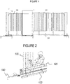
- Figure 2 illustrates the difficulty which occurs during assembly of a known bar gate such as that shown in Figure 1 . Since the zone in which the transverse channels of bars 100 are located is inside the substantially hollow horizontal beam 120 , it is very difficult to see whether the placed bars have the correct orientation. Two people are in fact therefore required to assemble such a known gate element, wherein the first looks via small openings at the otherwise covered outer end of the bar 100 to be fitted and rotates the bar 100 until the correct orientation is reached, and the second pushes the tensioning element 140 through the correctly oriented transverse channels. During the assembly a temporary positioning beam 122 can be used to hold the placed bars 100 at the correct height during threading, this positioning beam 122 being removed after proper anchoring of tensioning element 140 .
- FIG. 3 shows a bar 100 according to the present invention provided with a transverse channel 130 suitable for receiving a tensioning element 140 .
- Tensioning element 140 here also has the purpose of threading together different bars and of attaching the whole to the substantially vertical posts bounding the gate element.
- Tensioning element 140 can be a steel wire or other suitable slender element with sufficient stiffness.
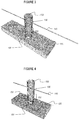
- the shown bar 100 has on at least one outer end 110 (only the lower outer end is shown here) an orienting means 151 which consists in the shown embodiment of two recesses lying diametrically opposite each other. These recesses 151 are formed in each case such that, at a correct orientation of the bar, they fit precisely into the corresponding protrusions 161 provided for this purpose in beam 120 .
- Figure 4 shows a variant of the bar according to the present invention wherein recess 151 in a hollow bar 100 takes the form of a slot. In order to facilitate assembly this slot has a somewhat widened entry side. This embodiment otherwise has the same operation and features as the above described embodiment of Figure 3 .
- the shown embodiments have the advantage that, due to the contact between the upper outer end of recesses 151 and protrusions 161 , bar 100 finds support on these protrusions 161 and so will not drop through beam 120 , even if this latter takes a substantially hollow form or if the opening in which bar 100 is placed passes through the whole of beam 120 .
- the positioning beam 122 can on the one hand be dispensed with and the load on tensioning element 140 can on the other be greatly reduced.
- Figure 5 shows a further variant of the bar according to the present invention, wherein recess 151 in outer end 110 of bar 100 is L-shaped or even stepped.
- This variant has the advantage that the placing of the bar in the beam takes place with a bayonet coupling, thereby obtaining both rotational and translational locking of the bar in the beam. This makes it even easier for the person placing the bars in the beam to make sure that the bar has reached the correct orientation. Furthermore, it is not possible after assembly to pull the bars upward out of the beam.
- Figure 6 shows a partial enlargement of the outer end of a bar 100 of the type shown in Figure 5 . Shown in Figure 6 is an optional additional recessed portion 159 which secures the bar against rotation following assembly.
- Figure 8 shows the corresponding beam 120 , wherein the recessed portions 162 for receiving the support surfaces 180 are clearly shown.
Landscapes
- Engineering & Computer Science (AREA)
- Civil Engineering (AREA)
- Structural Engineering (AREA)
- Reinforcement Elements For Buildings (AREA)
- Rod-Shaped Construction Members (AREA)
- Metal Extraction Processes (AREA)
- Refuge Islands, Traffic Blockers, Or Guard Fence (AREA)
Claims (12)
- Einrichtung, aufweisend mindestens einen Träger (120) eines Tors, ein Spannelement (140) zum Verspannen des Tors, und eine Mehrzahl von Stäben, wobei jeder Stab mindestens ein äußeres Ende (110) zur Verwendung mit dem Träger (120) aufweist, wobei der Stab mit einem transversalen Kanal (130) zum Aufnehmen des Spannelements versehen ist,
wobei das mindestens eine äußere Ende (110) ferner versehen ist mit einem Ausrichtungselement (151, 152), welches dazu eingerichtet ist, eine im Wesentlichen parallele Ausrichtung des transversalen Kanals (130) und des Trägers (120) beim Verbinden des Stabs (100) mit dem Träger (120) sicherzustellen, gekennzeichnet dadurch, dass das Ausrichtungselement mindestens eine periphere Aussparung (151,152) aufweist, welche relativ zu einer Längsachse des Stabs (100) einen vorbestimmten Winkel mit der Richtung des transversalen Kanals (130) bildet, wobei die mindestens eine periphere Aussparung (151, 152) ausgebildet ist, so dass eine untere Fläche eines Teils des Stabs (100), der an der Oberseite zu der Aussparung benachbart ist, eine Stützfläche (180) zum Verhindern einer weiteren Abwärtsbewegung des Stabs bildet. - Einrichtung gemäß Anspruch 1, wobei der vorbestimmte Winkel mit einem Winkel zwischen einem ausgesparten Abschnitt (162), der in dem Träger (120) angeordnet ist und der hinsichtlich Form im Wesentlichen mit der Stützfläche korrespondiert, und einer Längsachse des Trägers (120) korrespondiert.
- Einrichtung wie in Anspruch 1 oder 2 beansprucht, wobei das Ausrichtungselement zwei periphere Aussparungen (151), die einander diametral gegenüber liegen, aufweist.
- Einrichtung (100) wie in irgendeinem der Ansprüche 1-3 beansprucht, wobei die Aussparung (151) im Wesentlichen L-förmig oder gestuft ist.
- Einrichtung wie in irgendeinem der Ansprüche 1 bis 4 beansprucht, wobei die Aussparung (151) eine geweitete Eintrittsseite hat.
- Einrichtung wie in irgendeinem der Ansprüche 1 bis 5 beansprucht, wobei die wenigstens eine periphere Aussparung (152) ferner mit einer zusätzlichen Aussparung (159) versehen ist, welche den Stab (100) gegen eine auf die Montage folgende Rotation sichert.
- Einrichtung wie in irgendeinem der Ansprüche 1 bis 6 beansprucht, wobei eine obere Fläche (121) des Trägers (120) mit einem ausgesparten Abschnitt (162) versehen ist, der hinsichtlich Form im Wesentlichen mit der Stützfläche (180) des Stabs (100) korrespondiert.
- Einrichtung wie in irgendeinem der vorherigen Ansprüche beansprucht, wobei das Spannelement (140) eine Stahlstange aufweist.
- Tor (1), aufweisend die Einrichtung wie in irgendeinem der vorherigen Ansprüche 1 bis 8 beansprucht.
- Verfahren zum Herstellen eines Tors (1), aufweisend:- Verbinden einer Mehrzahl von Stäben (100), die einen transversalen Kanal (130) aufweisen, mit einem Träger (120), und- Hindurchführen eines Spannelements (140) durch den transversalen Kanal (130) jedes Stabs (100),wobei das Verbinden der Mehrzahl von Stäben (100), die den transversalen Kanal (130) aufweisen, mit dem Träger (120) bei einer Winkelausrichtung, welche durch Einbringen von Vorsprüngen in Aussparungen (151, 152) festgelegt ist, stattfindet,
wobei die Mehrzahl von Stäben (100) mit den Aussparungen (151) versehen ist und wobei der Träger mit den Vorsprüngen (161) versehen ist,
gekennzeichnet dadurch, dass die Aussparungen (151, 152) ausgebildet sind, so dass eine untere Fläche eines Teils des Stabs, der an der Oberseite zu der Aussparung benachbart ist, eine Stützfläche bildet und dass eine obere Fläche eines Teils, der an der Unterseite zu der Aussparung benachbart ist, eine Festhaltefläche bildet. - Verfahren wie in Anspruch 10 beansprucht, wobei die Aussparungen (151) im Wesentlichen L-förmig oder gestuft sind, und wobei das Verbinden jedes von der Mehrzahl von Stäben (100) mit dem Träger (120) ein Rotieren jedes der Mehrzahl von Stäben um ihre jeweilige Längsachse aufweist.
- Verfahren zum Herstellen eines Tors (1), aufweisend:- Verbinden einer Mehrzahl von Stäben (100) einer Einrichtung gemäß Anspruch 2 mit einem Träger (120) einer Einrichtung gemäß Anspruch 7, und- Hindurchführen eines Spannelements (140) durch den transversalen Kanal (130) jedes Stab (100),wobei das Verbinden der Mehrzahl von Stäben (100), die den transversalen Kanal (130) aufweisen, mit dem Träger (120) bei einer Winkelausrichtung, welche durch Einbringen der Stützfläche jedes Stabs (100) in die korrespondierenden ausgesparten Abschnitte (162) des Trägers festgelegt ist, stattfindet.
Priority Applications (1)
| Application Number | Priority Date | Filing Date | Title |
|---|---|---|---|
| PL12152574T PL2481879T3 (pl) | 2011-01-28 | 2012-01-26 | Pręt do bramy oraz sposób wytwarzania bramy |
Applications Claiming Priority (1)
| Application Number | Priority Date | Filing Date | Title |
|---|---|---|---|
| NL2006096A NL2006096C2 (nl) | 2011-01-28 | 2011-01-28 | Spijl voor een poort en werkwijze voor het vervaardigen van een poort. |
Publications (3)
| Publication Number | Publication Date |
|---|---|
| EP2481879A2 EP2481879A2 (de) | 2012-08-01 |
| EP2481879A3 EP2481879A3 (de) | 2012-10-24 |
| EP2481879B1 true EP2481879B1 (de) | 2017-06-14 |
Family
ID=45507615
Family Applications (1)
| Application Number | Title | Priority Date | Filing Date |
|---|---|---|---|
| EP12152574.5A Not-in-force EP2481879B1 (de) | 2011-01-28 | 2012-01-26 | Stab für ein Tor und Verfahren zur Herstellung eines Tors |
Country Status (4)
| Country | Link |
|---|---|
| EP (1) | EP2481879B1 (de) |
| DK (1) | DK2481879T3 (de) |
| NL (1) | NL2006096C2 (de) |
| PL (1) | PL2481879T3 (de) |
Families Citing this family (2)
| Publication number | Priority date | Publication date | Assignee | Title |
|---|---|---|---|---|
| NL2011046C2 (nl) | 2013-06-27 | 2015-01-05 | Heras B V | Afsluitdeel voor een poort of hekwerk en werkwijze voor het vervaardigen daarvan. |
| CN105134059B (zh) * | 2015-08-06 | 2017-03-08 | 佛山市南海鼎新机电设备科技有限公司 | 一种新型伸缩式平移门 |
Family Cites Families (3)
| Publication number | Priority date | Publication date | Assignee | Title |
|---|---|---|---|---|
| NL8302007A (nl) * | 1983-06-06 | 1985-01-02 | Heras Holding | Poort. |
| GB0325331D0 (en) * | 2003-10-30 | 2003-12-03 | Garfex Ltd | Gate |
| NL2000880C2 (nl) * | 2007-09-25 | 2009-03-26 | Crh Fencing & Security Group | Afsluitdeel en poort voorzien van een dergelijk afsluitdeel. |
-
2011
- 2011-01-28 NL NL2006096A patent/NL2006096C2/nl not_active IP Right Cessation
-
2012
- 2012-01-26 EP EP12152574.5A patent/EP2481879B1/de not_active Not-in-force
- 2012-01-26 PL PL12152574T patent/PL2481879T3/pl unknown
- 2012-01-26 DK DK12152574.5T patent/DK2481879T3/en active
Also Published As
| Publication number | Publication date |
|---|---|
| EP2481879A2 (de) | 2012-08-01 |
| NL2006096C2 (nl) | 2012-07-31 |
| DK2481879T3 (en) | 2017-09-18 |
| EP2481879A3 (de) | 2012-10-24 |
| PL2481879T3 (pl) | 2017-10-31 |
Similar Documents
| Publication | Publication Date | Title |
|---|---|---|
| US20240007047A1 (en) | Device and Method for Aligning a Solar Panel with Respect to a Roof-Mounted Installation Rail Prior to Installation | |
| US9908207B2 (en) | In-rail connector | |
| KR102011241B1 (ko) | 경사지에 설치 가능한 조립식 울타리 | |
| US11300180B2 (en) | Vertical cable railing assembly | |
| US8505880B2 (en) | Fence rail support system | |
| US8522505B2 (en) | Connector for boardwalk system | |
| US9228372B2 (en) | Fence rail and bracket system | |
| US11512491B2 (en) | Hollow post anchoring systems for decking and related methods | |
| EP3099984B1 (de) | Photovoltaisches solarmodulspannsystem und solarcarport | |
| EP2481879B1 (de) | Stab für ein Tor und Verfahren zur Herstellung eines Tors | |
| KR200461108Y1 (ko) | 수직지지대 하단부에 고정되는 받침대를 구비한 서포터 | |
| HUE025649T2 (en) | Scaffolding | |
| KR20120033608A (ko) | 각도조절이 가능한 난간 연결장치 | |
| US10815655B2 (en) | Connection device for fastening two elements, in particular for building construction | |
| US20170252902A1 (en) | Clamping System Using Wedge With Angle Transmission | |
| KR101251005B1 (ko) | 자동차 운반선에서 자동차 추락 방지용 턱의 고정장치 | |
| AU2011205150A1 (en) | A multi angle roof truss tie-down apparatus and method | |
| CN103746643A (zh) | 光伏阵列组装系统 | |
| KR20110011382A (ko) | 기둥 고정 장치 | |
| KR101266906B1 (ko) | 펜스용 체결구 | |
| KR20150137657A (ko) | 스페이스 프레임 연결유닛 및 이를 포함한 구조체 | |
| ES2656530T3 (es) | Elemento de unión insertable para un andamio, especialmente un andamio de construcción | |
| KR101849957B1 (ko) | 난간의 가로대 결합구조 | |
| KR20140020573A (ko) | 건축외장재 설치용 고정구 | |
| KR20160004232U (ko) | 난간 지주 어셈블리 |
Legal Events
| Date | Code | Title | Description |
|---|---|---|---|
| PUAI | Public reference made under article 153(3) epc to a published international application that has entered the european phase |
Free format text: ORIGINAL CODE: 0009012 |
|
| AK | Designated contracting states |
Kind code of ref document: A2 Designated state(s): AL AT BE BG CH CY CZ DE DK EE ES FI FR GB GR HR HU IE IS IT LI LT LU LV MC MK MT NL NO PL PT RO RS SE SI SK SM TR |
|
| AX | Request for extension of the european patent |
Extension state: BA ME |
|
| PUAL | Search report despatched |
Free format text: ORIGINAL CODE: 0009013 |
|
| AK | Designated contracting states |
Kind code of ref document: A3 Designated state(s): AL AT BE BG CH CY CZ DE DK EE ES FI FR GB GR HR HU IE IS IT LI LT LU LV MC MK MT NL NO PL PT RO RS SE SI SK SM TR |
|
| AX | Request for extension of the european patent |
Extension state: BA ME |
|
| RIC1 | Information provided on ipc code assigned before grant |
Ipc: E06B 11/02 20060101AFI20120917BHEP |
|
| 17P | Request for examination filed |
Effective date: 20130423 |
|
| RAP1 | Party data changed (applicant data changed or rights of an application transferred) |
Owner name: HERAS B.V. |
|
| 17Q | First examination report despatched |
Effective date: 20160407 |
|
| GRAP | Despatch of communication of intention to grant a patent |
Free format text: ORIGINAL CODE: EPIDOSNIGR1 |
|
| RIC1 | Information provided on ipc code assigned before grant |
Ipc: E06B 3/964 20060101ALN20161212BHEP Ipc: E06B 11/02 20060101AFI20161212BHEP |
|
| INTG | Intention to grant announced |
Effective date: 20170117 |
|
| GRAS | Grant fee paid |
Free format text: ORIGINAL CODE: EPIDOSNIGR3 |
|
| GRAA | (expected) grant |
Free format text: ORIGINAL CODE: 0009210 |
|
| AK | Designated contracting states |
Kind code of ref document: B1 Designated state(s): AL AT BE BG CH CY CZ DE DK EE ES FI FR GB GR HR HU IE IS IT LI LT LU LV MC MK MT NL NO PL PT RO RS SE SI SK SM TR |
|
| REG | Reference to a national code |
Ref country code: GB Ref legal event code: FG4D |
|
| REG | Reference to a national code |
Ref country code: CH Ref legal event code: EP Ref country code: AT Ref legal event code: REF Ref document number: 901135 Country of ref document: AT Kind code of ref document: T Effective date: 20170615 |
|
| REG | Reference to a national code |
Ref country code: CH Ref legal event code: NV Representative=s name: ARNOLD AND SIEDSMA AG, CH |
|
| REG | Reference to a national code |
Ref country code: IE Ref legal event code: FG4D |
|
| REG | Reference to a national code |
Ref country code: DE Ref legal event code: R096 Ref document number: 602012033348 Country of ref document: DE |
|
| REG | Reference to a national code |
Ref country code: NL Ref legal event code: FP |
|
| REG | Reference to a national code |
Ref country code: DK Ref legal event code: T3 Effective date: 20170914 |
|
| REG | Reference to a national code |
Ref country code: SE Ref legal event code: TRGR |
|
| REG | Reference to a national code |
Ref country code: NO Ref legal event code: T2 Effective date: 20170614 |
|
| REG | Reference to a national code |
Ref country code: LT Ref legal event code: MG4D |
|
| PG25 | Lapsed in a contracting state [announced via postgrant information from national office to epo] |
Ref country code: HR Free format text: LAPSE BECAUSE OF FAILURE TO SUBMIT A TRANSLATION OF THE DESCRIPTION OR TO PAY THE FEE WITHIN THE PRESCRIBED TIME-LIMIT Effective date: 20170614 Ref country code: ES Free format text: LAPSE BECAUSE OF FAILURE TO SUBMIT A TRANSLATION OF THE DESCRIPTION OR TO PAY THE FEE WITHIN THE PRESCRIBED TIME-LIMIT Effective date: 20170614 Ref country code: FI Free format text: LAPSE BECAUSE OF FAILURE TO SUBMIT A TRANSLATION OF THE DESCRIPTION OR TO PAY THE FEE WITHIN THE PRESCRIBED TIME-LIMIT Effective date: 20170614 Ref country code: GR Free format text: LAPSE BECAUSE OF FAILURE TO SUBMIT A TRANSLATION OF THE DESCRIPTION OR TO PAY THE FEE WITHIN THE PRESCRIBED TIME-LIMIT Effective date: 20170915 Ref country code: LT Free format text: LAPSE BECAUSE OF FAILURE TO SUBMIT A TRANSLATION OF THE DESCRIPTION OR TO PAY THE FEE WITHIN THE PRESCRIBED TIME-LIMIT Effective date: 20170614 |
|
| PG25 | Lapsed in a contracting state [announced via postgrant information from national office to epo] |
Ref country code: LV Free format text: LAPSE BECAUSE OF FAILURE TO SUBMIT A TRANSLATION OF THE DESCRIPTION OR TO PAY THE FEE WITHIN THE PRESCRIBED TIME-LIMIT Effective date: 20170614 Ref country code: RS Free format text: LAPSE BECAUSE OF FAILURE TO SUBMIT A TRANSLATION OF THE DESCRIPTION OR TO PAY THE FEE WITHIN THE PRESCRIBED TIME-LIMIT Effective date: 20170614 Ref country code: BG Free format text: LAPSE BECAUSE OF FAILURE TO SUBMIT A TRANSLATION OF THE DESCRIPTION OR TO PAY THE FEE WITHIN THE PRESCRIBED TIME-LIMIT Effective date: 20170914 |
|
| REG | Reference to a national code |
Ref country code: FR Ref legal event code: PLFP Year of fee payment: 7 |
|
| PG25 | Lapsed in a contracting state [announced via postgrant information from national office to epo] |
Ref country code: EE Free format text: LAPSE BECAUSE OF FAILURE TO SUBMIT A TRANSLATION OF THE DESCRIPTION OR TO PAY THE FEE WITHIN THE PRESCRIBED TIME-LIMIT Effective date: 20170614 Ref country code: RO Free format text: LAPSE BECAUSE OF FAILURE TO SUBMIT A TRANSLATION OF THE DESCRIPTION OR TO PAY THE FEE WITHIN THE PRESCRIBED TIME-LIMIT Effective date: 20170614 Ref country code: SK Free format text: LAPSE BECAUSE OF FAILURE TO SUBMIT A TRANSLATION OF THE DESCRIPTION OR TO PAY THE FEE WITHIN THE PRESCRIBED TIME-LIMIT Effective date: 20170614 Ref country code: CZ Free format text: LAPSE BECAUSE OF FAILURE TO SUBMIT A TRANSLATION OF THE DESCRIPTION OR TO PAY THE FEE WITHIN THE PRESCRIBED TIME-LIMIT Effective date: 20170614 |
|
| PG25 | Lapsed in a contracting state [announced via postgrant information from national office to epo] |
Ref country code: IS Free format text: LAPSE BECAUSE OF FAILURE TO SUBMIT A TRANSLATION OF THE DESCRIPTION OR TO PAY THE FEE WITHIN THE PRESCRIBED TIME-LIMIT Effective date: 20171014 Ref country code: SM Free format text: LAPSE BECAUSE OF FAILURE TO SUBMIT A TRANSLATION OF THE DESCRIPTION OR TO PAY THE FEE WITHIN THE PRESCRIBED TIME-LIMIT Effective date: 20170614 Ref country code: IT Free format text: LAPSE BECAUSE OF FAILURE TO SUBMIT A TRANSLATION OF THE DESCRIPTION OR TO PAY THE FEE WITHIN THE PRESCRIBED TIME-LIMIT Effective date: 20170614 |
|
| PGFP | Annual fee paid to national office [announced via postgrant information from national office to epo] |
Ref country code: LU Payment date: 20180129 Year of fee payment: 7 |
|
| REG | Reference to a national code |
Ref country code: DE Ref legal event code: R097 Ref document number: 602012033348 Country of ref document: DE |
|
| PGFP | Annual fee paid to national office [announced via postgrant information from national office to epo] |
Ref country code: NL Payment date: 20180126 Year of fee payment: 7 |
|
| PLBE | No opposition filed within time limit |
Free format text: ORIGINAL CODE: 0009261 |
|
| STAA | Information on the status of an ep patent application or granted ep patent |
Free format text: STATUS: NO OPPOSITION FILED WITHIN TIME LIMIT |
|
| PGFP | Annual fee paid to national office [announced via postgrant information from national office to epo] |
Ref country code: DE Payment date: 20180129 Year of fee payment: 7 Ref country code: GB Payment date: 20180129 Year of fee payment: 7 Ref country code: NO Payment date: 20180129 Year of fee payment: 7 Ref country code: DK Payment date: 20180125 Year of fee payment: 7 Ref country code: CH Payment date: 20180127 Year of fee payment: 7 |
|
| 26N | No opposition filed |
Effective date: 20180315 |
|
| PGFP | Annual fee paid to national office [announced via postgrant information from national office to epo] |
Ref country code: IE Payment date: 20180129 Year of fee payment: 7 Ref country code: AT Payment date: 20180119 Year of fee payment: 7 Ref country code: BE Payment date: 20180129 Year of fee payment: 7 Ref country code: SE Payment date: 20180129 Year of fee payment: 7 Ref country code: FR Payment date: 20180125 Year of fee payment: 7 |
|
| PG25 | Lapsed in a contracting state [announced via postgrant information from national office to epo] |
Ref country code: SI Free format text: LAPSE BECAUSE OF FAILURE TO SUBMIT A TRANSLATION OF THE DESCRIPTION OR TO PAY THE FEE WITHIN THE PRESCRIBED TIME-LIMIT Effective date: 20170614 |
|
| PG25 | Lapsed in a contracting state [announced via postgrant information from national office to epo] |
Ref country code: MC Free format text: LAPSE BECAUSE OF FAILURE TO SUBMIT A TRANSLATION OF THE DESCRIPTION OR TO PAY THE FEE WITHIN THE PRESCRIBED TIME-LIMIT Effective date: 20170614 |
|
| REG | Reference to a national code |
Ref country code: DE Ref legal event code: R119 Ref document number: 602012033348 Country of ref document: DE |
|
| REG | Reference to a national code |
Ref country code: DK Ref legal event code: EBP Effective date: 20190131 Ref country code: NO Ref legal event code: MMEP |
|
| REG | Reference to a national code |
Ref country code: CH Ref legal event code: PL |
|
| REG | Reference to a national code |
Ref country code: NL Ref legal event code: MM Effective date: 20190201 |
|
| REG | Reference to a national code |
Ref country code: AT Ref legal event code: MM01 Ref document number: 901135 Country of ref document: AT Kind code of ref document: T Effective date: 20190126 |
|
| GBPC | Gb: european patent ceased through non-payment of renewal fee |
Effective date: 20190126 |
|
| PG25 | Lapsed in a contracting state [announced via postgrant information from national office to epo] |
Ref country code: LU Free format text: LAPSE BECAUSE OF NON-PAYMENT OF DUE FEES Effective date: 20190126 |
|
| REG | Reference to a national code |
Ref country code: BE Ref legal event code: MM Effective date: 20190131 |
|
| REG | Reference to a national code |
Ref country code: IE Ref legal event code: MM4A |
|
| PG25 | Lapsed in a contracting state [announced via postgrant information from national office to epo] |
Ref country code: DE Free format text: LAPSE BECAUSE OF NON-PAYMENT OF DUE FEES Effective date: 20190801 Ref country code: FR Free format text: LAPSE BECAUSE OF NON-PAYMENT OF DUE FEES Effective date: 20190131 Ref country code: NO Free format text: LAPSE BECAUSE OF NON-PAYMENT OF DUE FEES Effective date: 20190131 Ref country code: NL Free format text: LAPSE BECAUSE OF NON-PAYMENT OF DUE FEES Effective date: 20190201 Ref country code: SE Free format text: LAPSE BECAUSE OF NON-PAYMENT OF DUE FEES Effective date: 20190127 |
|
| PG25 | Lapsed in a contracting state [announced via postgrant information from national office to epo] |
Ref country code: BE Free format text: LAPSE BECAUSE OF NON-PAYMENT OF DUE FEES Effective date: 20190131 |
|
| PG25 | Lapsed in a contracting state [announced via postgrant information from national office to epo] |
Ref country code: AT Free format text: LAPSE BECAUSE OF NON-PAYMENT OF DUE FEES Effective date: 20190126 Ref country code: LI Free format text: LAPSE BECAUSE OF NON-PAYMENT OF DUE FEES Effective date: 20190131 Ref country code: GB Free format text: LAPSE BECAUSE OF NON-PAYMENT OF DUE FEES Effective date: 20190126 Ref country code: CH Free format text: LAPSE BECAUSE OF NON-PAYMENT OF DUE FEES Effective date: 20190131 |
|
| PG25 | Lapsed in a contracting state [announced via postgrant information from national office to epo] |
Ref country code: DK Free format text: LAPSE BECAUSE OF NON-PAYMENT OF DUE FEES Effective date: 20190131 Ref country code: MT Free format text: LAPSE BECAUSE OF NON-PAYMENT OF DUE FEES Effective date: 20180126 Ref country code: IE Free format text: LAPSE BECAUSE OF NON-PAYMENT OF DUE FEES Effective date: 20190126 |
|
| REG | Reference to a national code |
Ref country code: AT Ref legal event code: UEP Ref document number: 901135 Country of ref document: AT Kind code of ref document: T Effective date: 20170614 |
|
| PG25 | Lapsed in a contracting state [announced via postgrant information from national office to epo] |
Ref country code: TR Free format text: LAPSE BECAUSE OF FAILURE TO SUBMIT A TRANSLATION OF THE DESCRIPTION OR TO PAY THE FEE WITHIN THE PRESCRIBED TIME-LIMIT Effective date: 20170614 |
|
| PGFP | Annual fee paid to national office [announced via postgrant information from national office to epo] |
Ref country code: PL Payment date: 20200103 Year of fee payment: 9 |
|
| PG25 | Lapsed in a contracting state [announced via postgrant information from national office to epo] |
Ref country code: HU Free format text: LAPSE BECAUSE OF FAILURE TO SUBMIT A TRANSLATION OF THE DESCRIPTION OR TO PAY THE FEE WITHIN THE PRESCRIBED TIME-LIMIT; INVALID AB INITIO Effective date: 20120126 Ref country code: PT Free format text: LAPSE BECAUSE OF FAILURE TO SUBMIT A TRANSLATION OF THE DESCRIPTION OR TO PAY THE FEE WITHIN THE PRESCRIBED TIME-LIMIT Effective date: 20170614 |
|
| PG25 | Lapsed in a contracting state [announced via postgrant information from national office to epo] |
Ref country code: MK Free format text: LAPSE BECAUSE OF NON-PAYMENT OF DUE FEES Effective date: 20170614 Ref country code: CY Free format text: LAPSE BECAUSE OF FAILURE TO SUBMIT A TRANSLATION OF THE DESCRIPTION OR TO PAY THE FEE WITHIN THE PRESCRIBED TIME-LIMIT Effective date: 20170614 |
|
| PG25 | Lapsed in a contracting state [announced via postgrant information from national office to epo] |
Ref country code: AL Free format text: LAPSE BECAUSE OF FAILURE TO SUBMIT A TRANSLATION OF THE DESCRIPTION OR TO PAY THE FEE WITHIN THE PRESCRIBED TIME-LIMIT Effective date: 20170614 |
|
| PG25 | Lapsed in a contracting state [announced via postgrant information from national office to epo] |
Ref country code: PL Free format text: LAPSE BECAUSE OF NON-PAYMENT OF DUE FEES Effective date: 20210126 |