EP2481259B1 - Rohrheizkörper und verfahren zur herstellung eines solchen rohrheizkörpers - Google Patents
Rohrheizkörper und verfahren zur herstellung eines solchen rohrheizkörpers Download PDFInfo
- Publication number
- EP2481259B1 EP2481259B1 EP10754932.1A EP10754932A EP2481259B1 EP 2481259 B1 EP2481259 B1 EP 2481259B1 EP 10754932 A EP10754932 A EP 10754932A EP 2481259 B1 EP2481259 B1 EP 2481259B1
- Authority
- EP
- European Patent Office
- Prior art keywords
- silicone
- tubular heater
- tubular
- heater device
- insulating material
- Prior art date
- Legal status (The legal status is an assumption and is not a legal conclusion. Google has not performed a legal analysis and makes no representation as to the accuracy of the status listed.)
- Revoked
Links
Images
Classifications
-
- H—ELECTRICITY
- H05—ELECTRIC TECHNIQUES NOT OTHERWISE PROVIDED FOR
- H05B—ELECTRIC HEATING; ELECTRIC LIGHT SOURCES NOT OTHERWISE PROVIDED FOR; CIRCUIT ARRANGEMENTS FOR ELECTRIC LIGHT SOURCES, IN GENERAL
- H05B3/00—Ohmic-resistance heating
- H05B3/40—Heating elements having the shape of rods or tubes
- H05B3/42—Heating elements having the shape of rods or tubes non-flexible
- H05B3/48—Heating elements having the shape of rods or tubes non-flexible heating conductor embedded in insulating material
Definitions
- the invention relates to a tubular heater and a method for producing such a tubular heater.
- tubular heaters are often used for example in electric heaters such as ovens to heat them.
- electric heaters such as ovens
- the trend is towards increasingly high operating temperatures, in particular for pyrolysis of the oven muffle, and, for reasons of energy efficiency, increasingly thicker thermal insulation.
- This development means that the temperatures in the connection area of a tubular heater continue to rise.
- the unheated length of the tubular heater could be increased.
- the space inside the oven is very limited and a certain power is required, this is usually not.
- the EP 0858084 A1 describes such a tubular heater with a tube jacket and a heating conductor extending therein.
- an insulating material is introduced, which is impregnated with silicone oil.
- a stopper made of Teflon is applied, from which a connection protrudes.
- the invention has for its object to provide a pipe radiator mentioned above and a method for its production, which can be avoided with the problems of the prior art and above all allow higher temperatures in the connection area or at the connection section of a tubular heater.
- the tubular heater has a tubular jacket and at least one heating conductor extending in the tubular jacket, wherein insulating material is provided therebetween, usually magnesium oxide or the like.
- the heating conductor is provided in an attachment section of the tubular heater with an electrical connection, for example in a simple plug form.
- the insulating material is mixed with silicone in the area of the connection section or contains silicone in order to prevent the penetration of water or moisture into the pipe jacket or into the pipe heater.
- the silicone has an RTI value of at least 150.
- the silicone has an RTI value of at least 200, particularly advantageously at least 220.
- the RTI value (Relative Temperature Index) is a measure of the thermal aging resistance according to UL, which, so to speak the US VDE is. Normally used sealing qualities of silicone for electric tubular heaters have an RTI value of maximum 105.
- Another advantage of using silicone with such a high RTI value is that previously used polymers or silicone crosslinkers for silicones of the low temperature range can still be used.
- the silicone may be in the form of an oil or resin and then introduced into the tubular heater to impregnate or coat the insulating material in the foremost region. It can be in polymer form. It can penetrate a few mm into the tubular heater, but should not penetrate too far, otherwise the operating temperature of the tubular heater is too high for the silicone, even at high RTI value. So it can be beneficial introduced or penetrate maximally 10mm deep.
- such a silicone can advantageously be designed with respect to combustibility such that it has at least fire protection class HB, particularly advantageously even V-0.
- a silicone crosslinker may be provided or it may be added.
- the normal insulating material is introduced between the heating conductor and the tube jacket and then in the connection section just the special silicone. This can be solidified or cured or bonded during or after the introduction. Subsequently, a conventional insulating bead can be attached to the pipe jacket as a conclusion of the tubular heater, possibly even with a conventional sealant in between.
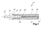
- FIG. 1 a section through a tubular heater according to the invention shown.
- the tubular heater 11 has a tubular jacket 13, in which a coiled heating conductor 15 extends along the center longitudinal axis shown in phantom.
- Pipe jacket 13 and heating element 15 are advantageously formed as from the prior Technique known.
- An intermediate space 17 between the heating conductor 15 and the tube jacket 13 is filled with an insulating material 18.
- this insulating material may be in pulverulent or granular form and, for example, also compressed in the tube jacket 13.
- the tubular heater 11 is stable and the heating conductor 15 can not come into contact with the tube jacket 13 under any circumstances.
- connection portion 20 specifically where the tube shell 13 has an end 21 which is open to the left.
- end 21 a likewise known per se Isolierperle 23 is introduced, advantageously made of plastic or ceramic material. It can be fixed or glued with an additional sealing compound 24 and be held centrally in the tube shell 13.
- connection portion 20 with Isolierperle 23 and terminal pin 25 largely corresponds to the prior art.
- insulating material 18 In the right area of the tubular heater 11 in Fig. 1 is the obliquely to the top right dashed illustrated insulating material 18 is present.
- the insulating material 18 extends up to the sealing compound 24.
- the insulating material 18 according to the invention the novel silicone mixed, so that a mixing region 28 is formed, which is shown diagonally dashed left above.
- This silicone for the mixing region 28 is formed as described above, so is an input called silicone material and may be liquid or pasty. Thus it can be filled through the open end 21 of the tubular jacket 13 to mix with the granular insulating material 18 and, if necessary, cured.
- the mixing region 28 with the silicone extends from the sealant 24 to the right into the tube jacket 13. If the sealing compound 24 is omitted, the mixing area 28 with the silicone can also be connected directly to the insulating bead 23. Furthermore, the mixing region 28 extends to the right until just before the connection of the connecting bolt 25 to the heating conductor 15 or the connecting region 26. However, this does not necessarily have to be the case.
- the transition between the mixing region 28 and the region with the insulating material 18 without silicone right next to it is very abrupt or abrupt, namely as a line or as a boundary layer 29.
- the length of the mixing region 28 may be a few mm, for example 10mm to 20mm or even 40mm
- Examples of possibly used terminal insulation materials or corresponding silicones are from the manufacturer Wacker Chemie AG, Kunststoff, silicones with the designation ELASTOSIL A 234 or ELASTOSIL RT 772.
- the first silicone has an RTI value of 150 and is in the fire protection class HB.
- the second silicone even has an RTI value of 200 and is in the same fire protection class.
- Dow Corning Corporation USA, has a 3120 silicone which has an RTI of 220 and is also in fire safety class HB.
- the first and the third said silicone material is in liquid form, the second silicone material is pasty. All silicones can be on Known manner be introduced into the tube jacket 13 and in the insulating material and then cured or bonded.
Landscapes
- Resistance Heating (AREA)
- Laminated Bodies (AREA)
- Compositions Of Macromolecular Compounds (AREA)
Description
- Die Erfindung betrifft einen Rohrheizkörper sowie ein Verfahren zur Herstellung eines solchen Rohrheizkörpers.
- Aus der
DE 1083450 ist der grundsätzliche Aufbau eines solchen Rohrheizkörpers bekannt. In einem Metallrohr als Mantel verläuft ein üblicherweise gewendelter Heizdraht. Durch ein Auffüllen des Mantels mit kornförmigem Isoliermaterial, insbesondere Magnesiumoxyd, wird der Heizdraht gegen den Mantel isoliert. An einem Anschlussende des Rohrheizkörpers wird der Heizdraht mit einem Anschlussstift verbunden bzw. auf diesen aufgeschoben, wobei der Anschlussstift zentrisch zum Mantel verläuft und aus diesem herausragt. Der Anschlussstift ist durch einen Isolierkörper aus Kunststoff oder Keramik gegen den Mantel isoliert und wird dadurch auch in seiner Lage fixiert. - Derartige Rohrheizkörper werden beispielsweise in Elektrowärmegeräten wie Backöfen häufig verwendet zu deren Beheizung. Bei Backöfen geht jedoch die Entwicklung in die Richtung, dass einerseits höhere Betriebstemperaturen, insbesondere für eine Reinigung der Backofenmuffel mittels Pyrolyse, und andererseits aus Gründen der Energieeffizienz immer dickere Wärmedämmungen eingesetzt werden. Diese Entwicklung führt dazu, dass die Temperaturen im Anschlussbereich eines Rohrheizkörpers immer weiter steigen. Zwar könnte, um diesem Problem zu begegnen, die unbeheizte Länge des Rohrheizkörpers vergrößert werden. Da jedoch der Platz im Inneren des Backofens sehr begrenzt ist und eine bestimmte Leistung gefordert wird, geht dies in der Regel nicht.
- Die
EP 0858084 A1 beschreibt einen solchen Rohrheizkörper mit einem Rohrmantel und einem darin verlaufenden Heizleiter. Im Bereich eines Anschlussabschnitts am Ende des Rohrheizkörpers ist ein Isoliermaterial eingebracht, das mit Silikonöl imprägniert ist. Darauf wird dann ein Stopfen aus Teflon aufgebracht, aus dem ein Anschluss heraussteht. - Aus der
FR 2754128 A1 - Aus der
EP 1296539 A1 ist ein weiterer gattungsgemäßer Rohrheizkörper bekannt, in dessen Ende als Anschlussabschnitt ebenfalls Kunststoff als Isoliermaterial eingebracht ist, wobei davor ein Silikonstopfen gesetzt ist. - Der Erfindung liegt die Aufgabe zugrunde, einen eingangs genannten Rohrheizkörper sowie ein Verfahren zu seiner Herstellung zu schaffen, mit denen Probleme des Standes der Technik vermieden werden können und die vor allem höhere Temperaturen im Anschlussbereich bzw. am Anschlussabschnitt eines Rohrheizkörpers ermöglichen.
- Gelöst wird diese Aufgabe durch einen Rohrheizkörper mit den Merkmalen des Anspruchs 1 sowie ein Verfahren zu seiner Herstellung mit den Merkmalen des Anspruchs 7. Vorteilhafte sowie bevorzugte Ausgestaltungen der Erfindung sind Gegenstand der weiteren Ansprüche und werden im Folgenden näher erläutert. Der Wortlaut der Ansprüche wird dabei durch ausdrückliche Bezugnahme zum Inhalt der Beschreibung gemacht. Manche der nachfolgend genannten Merkmale werden nur für den Rohrheizkörper oder nur für das Herstellungsverfahren genannt. Sie sollen jedoch unabhängig davon sowohl für den Rohrheizkörper als auch für das Herstellungsverfahren gelten können.
- Es ist vorgesehen, dass der Rohrheizkörper einen Rohrmantel und mindestens einen in dem Rohrmantel verlaufenden Heizleiter aufweist, wobei dazwischen Isoliermaterial vorgesehen ist, üblicherweise Magnesiumoxyd odgl.. Der Heizleiter ist in einem Anschlussabschnitt des Rohrheizkörpers mit einem elektrischen Anschluss versehen, beispielsweise in einfacher Steckerform. Erfindungsgemäß ist im Bereich des Anschlussabschnitts das Isoliermaterial mit Silikon vermischt bzw. enthält Silikon, um das Eindringen von Wasser bzw. Feuchtigkeit in den Rohrmantel bzw. in den Rohrheizkörper zu verhindern. Das Silikon weist einen RTI-Wert von mindestens 150 auf. Vorteilhaft weist das Silikon einen RTI-Wert von mindestens 200 auf, besonders vorteilhaft sogar mindestens 220. Der RTI-Wert (Relative Temperature Index) ist ein Maß für die thermische Alterungsbeständigkeit gemäß UL, welcher sozusagen die US-amerikanische VDE ist. Üblicherweise verwendete Verschlussqualitäten von Silikon für elektrische Rohrheizkörper haben einen RTI-Wert von maximal 105.
- So werden eben auch höhere Temperaturen im Anschlussabschnitt des Rohrheizkörpers ermöglicht, ohne dass die elektrische Isolierung bzw. die Funktionsfähigkeit und Sicherheit des Rohrheizkörpers in Mitleidenschaft gezogen werden bei gleichzeitigem Schutz gegen Eindringen von Wasser bzw. Feuchtigkeit in den Rohrheizkörper. Alternative Materialien wie in der Verarbeitung sehr aufwendiges Teflon oder das in der
DE 41 22 657 A1 beschriebene PPS als hochtemperaturbeständiges Thermoplast sind erheblich aufwendig und teurer und können somit vermieden werden. Es geht also erfindungsgemäß nicht nur darum, Silikon an sich zusammen mit dem Isoliermaterial zu verwenden bzw. zu vermischen, sondern um die Verwendung von bestimmten Silikonqualitäten mit einem genannten hohen RTI-Wert. - Ein weiterer Vorteil der Verwendung von Silikon mit einem solchen hohen RTI-Wert liegt darin, dass bislang verwendete Polymere bzw. Silikonvernetzer für Silikone aus dem Niedrig-Temperaturbereich auch weiterhin verwendet werden können.
- Das Silikon kann in Form eines Öles oder Harzes vorliegen und dann in den Rohrheizkörper eingebracht werden, um das Isoliermaterial in dem vordersten Bereich bzw. dem Anschlussabschnitt zu durchtränken oder zu benetzen bzw. zu umhüllen. Es kann in Polymer-Form vorliegen. Es kann einige mm weit in den Rohrheizkörper eindringen, sollte aber nicht zu weit eindringen, da ansonsten die Betriebstemperatur des Rohrheizkörpers zu hoch wird für das Silikon, selbst bei hohem RTI-Wert. So kann es vorteilhaft maximal 10mm tief eingebracht sein bzw. eindringen.
- Des weiteren kann vorteilhaft ein solches Silikon bzgl. der Brennbarkeit derart ausgebildet sein, dass es mindestens Brandschutzklasse HB aufweist, besonders vorteilhaft sogar V-0.
- In nochmals weiterer Ausgestaltung der Erfindung kann ein Silikonvernetzer vorgesehen sein bzw. er kann beigemengt werden.
- Zur Herstellung des erfindungsgemäßen Rohrheizkörpers wird wie üblich das normale Isoliermaterial zwischen Heizleiter und Rohrmantel eingebracht und dann im Anschlussabschnitt eben das spezielle Silikon. Dieses kann während bzw. nach dem Einbringen verfestigt bzw. ausgehärtet oder gebunden werden. Anschließend kann eine übliche Isolierperle am Rohrmantel befestigt werden als Abschluss des Rohrheizkörpers, möglicherweise noch mit einer üblichen Dichtmasse dazwischen.
- Diese und weitere Merkmale gehen außer aus den Ansprüchen auch aus der Beschreibung und der Zeichnung hervor, wobei die einzelnen Merkmale jeweils für sich allein oder zu mehreren in Form von Unterkombination bei einer Ausführungsform der Erfindung und auf anderen Gebieten verwirklicht sein und vorteilhafte sowie für sich schutzfähige Ausführungen darstellen können, für die hier Schutz beansprucht wird. Die Unterteilung der Anmeldung in einzelne Abschnitte sowie Zwischen-Überschriften beschränken die unter diesen gemachten Aussagen nicht in ihrer Allgemeingültigkeit.
- In der Zeichnung ist in
Fig. 1 ein Schnitt durch einen erfindungsgemäßen Rohrheizkörper dargestellt. Der Rohrheizkörper 11 weist einen Rohrmantel 13 auf, in dem ein gewendelter Heizleiter 15 entlang der strichpunktiert dargestellten Mittellängsachse verläuft. Rohrmantel 13 und Heizleiter 15 sind vorteilhaft ausgebildet wie aus dem Stand der Technik bekannt. Ein Zwischenraum 17 zwischen dem Heizleiter 15 und dem Rohrmantel 13 ist mit einem Isoliermaterial 18 gefüllt. Dieses Isoliermaterial kann wie vorbeschrieben Magnesiumoxyd in pulveriger bzw. körniger Form sein und beispielsweise auch verdichtet sein in dem Rohrmantel 13. So ist der Rohrheizkörper 11 stabil und der Heizleiter 15 kann auf keinen Fall in Kontakt mit dem Rohrmantel 13 kommen. - Der linke Bereich des Rohrheizkörpers 11 bildet einen Anschlussabschnitt 20, und zwar dort, wo der Rohrmantel 13 ein Ende 21 aufweist, welches nach links offen ist. In dieses Ende 21 ist eine ebenfalls an sich bekannte Isolierperle 23 eingebracht, vorteilhaft aus Kunststoff oder Keramikmaterial. Sie kann mit einer zusätzlichen Dichtmasse 24 befestigt bzw. verklebt sein und zentrisch in dem Rohrmantel 13 gehalten werden.
- Durch eine zentrische Bohrung der Isolierperle 23 läuft ein Anschlussbolzen 25, vorzugsweise ein Metallstift. An seinem linken aus dem Rohrmantel 13 stehenden Ende kann ein an sich bekannter elektrischer Anschluss vorgesehen sein. An seinem rechten, in den Rohrmantel 13 hinein weisenden Ende weist er einen verjüngten Verbindungsbereich 26 auf, an dem der Heizleiter 15 auf grundsätzlich bekannte Art und Weise kontaktiert und befestigt ist. Auch der Anschlussabschnitt 20 mit Isolierperle 23 und Anschlussbolzen 25 entspricht weitgehend dem Stand der Technik.
- Im rechten Bereich des Rohrheizkörpers 11 in
Fig. 1 ist das schräg nach rechts oben gestrichelt dargestellte Isoliermaterial 18 vorhanden. Das Isoliermaterial 18 erstreckt sich bis zu der Dichtmasse 24. In dem daneben angrenzenden Bereich ist dem Isoliermaterial 18 erfindungsgemäß das neuartige Silikon beigemischt, so dass ein Mischbereich 28 entsteht, der schräg nach links oben gestrichelt dargestellt ist. Dieses Silikon für den Mischbereich 28 ist wie vorbeschrieben ausgebildet, ist also ein eingangs genanntes Silikon-Material und kann flüssig oder pastös sein. So kann es durch das offene Ende 21 des Rohrmantels 13 eingefüllt werden um sich mit dem körnigen Isoliermaterial 18 zu vermischen und, falls notwendig, ausgehärtet werden. - Im hier dargestellten Ausführungsbeispiel erstreckt sich der Mischbereich 28 mit dem Silikon von der Dichtmasse 24 weg nach rechts in den Rohrmantel 13 hinein. Wird die Dichtmasse 24 weggelassen, kann der Mischbereich 28 mit dem Silikon auch direkt an die Isolierperle 23 anschließen. Des weiteren erstreckt sich der Mischbereich 28 nach rechts bis kurz vor die Verbindung des Anschlussbolzens 25 an den Heizleiter 15 bzw. den Verbindungsbereich 26. Dies muss aber nicht unbedingt so sein. Der Übergang zwischen dem Mischbereich 28 und dem Bereich mit dem Isoliermaterial 18 ohne Silikon rechts daneben ist sehr abrupt bzw. schlagartig, nämlich als Linie bzw. als Grenzschicht 29. Die Länge des Mischbereichs 28 kann einige mm betragen, beispielsweise 10mm bis 20mm oder sogar 40mm
- Beispiele für möglicherweise verwendete Anschluss-Isoliermaterialien bzw. entsprechende Silikone sind vom Hersteller Wacker Chemie AG, München, Silikone mit der Bezeichnung ELASTOSIL A 234 oder ELASTOSIL RT 772. Das erste Silikon weist einen RTI-Wert von 150 auf und ist in der Brandschutzklasse HB. Das zweite Silikon weist sogar einen RTI-Wert von 200 auf und ist in derselben Brandschutzklasse.
- Des weiteren gibt es von der Firma Dow Corning Corporation, USA, ein Silikon 3120, welches einen RTI-Wert von 220 aufweist und ebenfalls in der Brandschutzklasse HB ist.
- Das erste und das dritte genannte Silikonmaterial liegt in flüssiger Form vor, das zweite Silikonmaterial ist pastös. Alle Silikone können auf an sich bekannte Art und Weise in den Rohrmantel 13 und in das Isoliermaterial eingebracht werden und dann gehärtet bzw. gebunden werden.
Claims (8)
- Rohrheizkörper mit einem Rohrmantel und einem in dem Rohrmantel verlaufenden Heizleiter, wobei zwischen Heizleiter und Rohrmantel Isoliermaterial vorgesehen ist und der Heizleiter in einem Anschlussabschnitt des Rohrheizkörpers einen elektrischen Anschluss aufweist, wobei im Bereich des Anschlussabschnitts das Isoliermaterial mit Silikon vermischt ist bzw. Silikon enthält zur Verhinderung des Eindringens von Wasser bzw. Feuchtigkeit in den Rohrmantel bzw. in den Rohrheizkörper, dadurch gekennzeichnet, dass das Silikon einen RTI-Wert von mindestens 150 aufweist.
- Rohrheizkörper nach Anspruch 1, dadurch gekennzeichnet, dass das Silikon für den Anschlussabschnitt einen RTI-Wert von mindestens 200 aufweist, insbesondere mindestens 220.
- Rohrheizkörper nach Anspruch 1 oder 2, dadurch gekennzeichnet, dass das Silikon in Form eines Harzes oder Öles vorliegt vor dem Vermischen mit dem Isoliermaterial.
- Rohrheizkörper nach einem der vorhergehenden Ansprüche, dadurch gekennzeichnet, dass das Silikon in Polymer-Form vorliegt.
- Rohrheizkörper nach Anspruch 4, dadurch gekennzeichnet, dass das Polymer einen Vernetzer aufweist.
- Rohrheizkörper nach einem der vorhergehenden Ansprüche, dadurch gekennzeichnet, dass die Brennbarkeit des verwendeten Silikons mindestens Brandschutzklasse HB aufweist, vorzugsweise mindestens V-0.
- Verfahren zur Herstellung eines Rohrheizkörpers nach einem der vorhergehenden Ansprüche, dadurch gekennzeichnet, dass übliches Isoliermaterial zwischen Heizleiter und Rohrmantel eingebracht und dann im Anschlussabschnitt ein Silikon mit einem RTI-Wert von mindestens 150 eingebracht wird zur Vermischung mit dem Isoliermaterial, wobei das Silikon während bzw. nach dem Einbringen verfestigt bzw. ausgehärtet oder gebunden wird.
- Verfahren nach Anspruch 7, dadurch gekennzeichnet, dass das eingebrachte Silikon nur wenige mm tief in den Anschlussabschnitt eingebracht wird bzw. eindringt, vorzugsweise maximal 3mm bis 10mm tief.
Priority Applications (1)
| Application Number | Priority Date | Filing Date | Title |
|---|---|---|---|
| PL10754932T PL2481259T3 (pl) | 2009-09-25 | 2010-09-17 | Grzejnik rurowy i sposób wytwarzania takiego grzejnika rurowego |
Applications Claiming Priority (2)
| Application Number | Priority Date | Filing Date | Title |
|---|---|---|---|
| DE102009048495A DE102009048495A1 (de) | 2009-09-25 | 2009-09-25 | Rohrheizkörper und Verfahren zur Herstellung eines solchen Rohrheizkörpers |
| PCT/EP2010/063728 WO2011036105A1 (de) | 2009-09-25 | 2010-09-17 | Rohrheizkörper und verfahren zur herstellung eines solchen rohrheizkörpers |
Publications (2)
| Publication Number | Publication Date |
|---|---|
| EP2481259A1 EP2481259A1 (de) | 2012-08-01 |
| EP2481259B1 true EP2481259B1 (de) | 2015-07-01 |
Family
ID=43085906
Family Applications (1)
| Application Number | Title | Priority Date | Filing Date |
|---|---|---|---|
| EP10754932.1A Revoked EP2481259B1 (de) | 2009-09-25 | 2010-09-17 | Rohrheizkörper und verfahren zur herstellung eines solchen rohrheizkörpers |
Country Status (5)
| Country | Link |
|---|---|
| EP (1) | EP2481259B1 (de) |
| DE (1) | DE102009048495A1 (de) |
| ES (1) | ES2546510T3 (de) |
| PL (1) | PL2481259T3 (de) |
| WO (1) | WO2011036105A1 (de) |
Families Citing this family (6)
| Publication number | Priority date | Publication date | Assignee | Title |
|---|---|---|---|---|
| DE102015102728A1 (de) | 2015-02-25 | 2016-08-25 | Eltra Heizelemente Gmbh | Elektrischer Rohrheizkörper und Verfahren zum Herstellen des elektrischen Rohrheizkörpers |
| DE102015212916A1 (de) | 2015-07-09 | 2017-01-12 | E.G.O. Elektro-Gerätebau GmbH | Kochfeld |
| EP4382807A1 (de) | 2022-12-09 | 2024-06-12 | E.G.O. Elektro-Gerätebau GmbH | Backofen und verfahren zum betrieb eines backofens |
| DE102023201626A1 (de) | 2023-02-22 | 2024-08-22 | E.G.O. Elektro-Gerätebau GmbH | Rohrheizkörper und Verfahren zur Herstellung eines Rohrheizkörpers |
| DE102023107504A1 (de) | 2023-03-24 | 2024-10-10 | E.G.O. Elektro-Gerätebau GmbH | Backofen |
| EP4464941A1 (de) | 2023-05-16 | 2024-11-20 | E.G.O. Elektro-Gerätebau GmbH | Verfahren zum betrieb eines backofens und backofen |
Citations (3)
| Publication number | Priority date | Publication date | Assignee | Title |
|---|---|---|---|---|
| FR2754128A1 (fr) | 1996-09-27 | 1998-04-03 | Vulcanic | Dispositif de chauffage electrique, procede de fabrication et radiateur ainsi equipe |
| EP0858084A1 (de) | 1997-02-07 | 1998-08-12 | I.R.C.A. S.p.a. Industria Resistenze Corazzate e Affini | Herstellungsverfahren für geschützte Widerstandselemente und nach diesem Verfahren hergestelltes Widerstandselement |
| EP1296539A1 (de) | 2001-09-21 | 2003-03-26 | Seb S.A. | Verfahren zur Herstellung von keramischen Heizelementen |
Family Cites Families (2)
| Publication number | Priority date | Publication date | Assignee | Title |
|---|---|---|---|---|
| BE556965A (de) | 1956-04-25 | |||
| DE4122657A1 (de) | 1991-07-09 | 1993-01-14 | Licentia Gmbh | Feuchtigkeitsdichter abschluss fuer elektrische mantelrohrheizkoerper |
-
2009
- 2009-09-25 DE DE102009048495A patent/DE102009048495A1/de not_active Ceased
-
2010
- 2010-09-17 ES ES10754932.1T patent/ES2546510T3/es active Active
- 2010-09-17 PL PL10754932T patent/PL2481259T3/pl unknown
- 2010-09-17 EP EP10754932.1A patent/EP2481259B1/de not_active Revoked
- 2010-09-17 WO PCT/EP2010/063728 patent/WO2011036105A1/de not_active Ceased
Patent Citations (3)
| Publication number | Priority date | Publication date | Assignee | Title |
|---|---|---|---|---|
| FR2754128A1 (fr) | 1996-09-27 | 1998-04-03 | Vulcanic | Dispositif de chauffage electrique, procede de fabrication et radiateur ainsi equipe |
| EP0858084A1 (de) | 1997-02-07 | 1998-08-12 | I.R.C.A. S.p.a. Industria Resistenze Corazzate e Affini | Herstellungsverfahren für geschützte Widerstandselemente und nach diesem Verfahren hergestelltes Widerstandselement |
| EP1296539A1 (de) | 2001-09-21 | 2003-03-26 | Seb S.A. | Verfahren zur Herstellung von keramischen Heizelementen |
Non-Patent Citations (10)
| Title |
|---|
| "Auszug aus Dubbel Taschenbuch für den Maschinenbau", 1 January 1997, article "Werkstofftechnik - 4 Kunststoffe", pages: E70 - E71, XP055290060 |
| "ELASTOSIL® RT772", WACKER, 11 December 2015 (2015-12-11), XP055290096 |
| "Lehrbuch der Anorganische Chemie", article RIEDEL: "Die Elemente der Hauptgruppe", pages: 542 - 544, XP055290105 |
| "Lehrbuch der Organischen Chemie", 1 January 1998, article BEYER ET AL.: "Organische Verbindungn einiger Nichtmetalle", pages: 190, XP055290101 |
| "Relativen Temperaturindex", WIKIPEDIA, DER FREIEN ENZYKLOPADIE, 1 May 2009 (2009-05-01), XP055290056, Retrieved from the Internet <URL:https://de.wikipedia.org/wiki/Relativer_Temperaturindex> |
| "Textilpflegesymbol", WIKIPEDIA, DER FREIEN ENZYKLOPADIE, 4 February 2005 (2005-02-04), XP055290092 |
| "Typenübersicht von ELASTOSIL® Siliconkautschuk für die Appliance- Industrie", WACKER SILICONES, 2005, XP055290070 |
| ANONYMOUS: "ELASTOSIL® A234 WHITE CARTRIDGE", WACKER SILICONES, 18 June 2008 (2008-06-18), XP055290074 |
| ANONYMOUS: "UL 746B Standard for polymeric materials - long term property evaluations", UL, - 4 April 2013 (2013-04-04), pages 1 - 3, XP055289156 |
| HOMEPAGE DES UNDERWRITERS LABORATORIES, 22 March 2016 (2016-03-22) |
Also Published As
| Publication number | Publication date |
|---|---|
| DE102009048495A1 (de) | 2011-04-07 |
| EP2481259A1 (de) | 2012-08-01 |
| WO2011036105A1 (de) | 2011-03-31 |
| PL2481259T3 (pl) | 2015-12-31 |
| ES2546510T3 (es) | 2015-09-24 |
Similar Documents
| Publication | Publication Date | Title |
|---|---|---|
| WO2011036105A1 (de) | Rohrheizkörper und verfahren zur herstellung eines solchen rohrheizkörpers | |
| DE102011106727B3 (de) | Stecker für feuchtigkeitsgeschützte elektrische Steckverbindung | |
| DE102015114886A1 (de) | Heizvorrichtung für Fluide und Verfahren zur Herstellung einer solchen Heizvorrichtung | |
| DE112014001580T5 (de) | Ummantelter elektrischer Draht mit einer Klemme | |
| DE102018101195B4 (de) | Elektrische Vorrichtung mit rohrförmigem Metallmantel und darin aufgenommenem Isolierstoffkörper | |
| DE102006005322B4 (de) | Rohrheizkörper mit Isoliermasse im Anschlussendenbereich | |
| DE102009044877A1 (de) | Elektrische Heizpatrone mit Anschlussleitung | |
| DE19839651B4 (de) | Chemisch weitgehend resistente, schlauchförmige Ummantelung für einen Heizkörper einer elektrischen Heizvorrichtung | |
| EP2507868A1 (de) | Verfahren zur herstellung einer versiegelten verbindung | |
| WO2017186239A1 (de) | Zündkerze | |
| DE102015102728A1 (de) | Elektrischer Rohrheizkörper und Verfahren zum Herstellen des elektrischen Rohrheizkörpers | |
| EP3105841B1 (de) | Kohlebürstenanordnung | |
| DE102014018979A1 (de) | Faserverbundbauteil | |
| DE102004050001A1 (de) | Crimpverbindung | |
| EP1641728B1 (de) | Verfahren zur herstellung eines isolierenden keramik-verbund-werkstoffes und isolierender keramik-verbund-werkstoff | |
| DD222169A5 (de) | Anordnung zum verbinden von elektrischen, kunststoffisolierten leitern | |
| EP1487074A1 (de) | Hüllkörper für ein Hochspannungskabel und Verfahren zu seiner Herstellung | |
| DE102016217619A1 (de) | Herstellungsverfahren für ein elektrisches Betriebsmittel und elektrisches Betriebsmittel | |
| DE102009061111B3 (de) | Anschlussvorrichtung zum Anschluss eines Widerstandsheizleiters an eine elektrische Versorgung | |
| DE102023201626A1 (de) | Rohrheizkörper und Verfahren zur Herstellung eines Rohrheizkörpers | |
| DE102010016760A1 (de) | Thermoelement zum Erfassen von Temperaturen im Hochtemperaturbereich und Verfahren zu dessen Herstellung | |
| DE102014009467A1 (de) | Elektrische Verbindung, Verfahren zu deren Herstellung und Verwendung eines Schutzlacks | |
| DE112014006287B4 (de) | Elektrischer Leiter mit einer Mehrzahl von Einzeldrähten und Herstellungsverfahren hierfür | |
| DE2410451A1 (de) | Feuchtigkeitsdichter abschluss fuer elektrische rohrheizkoerper | |
| EP1867933B1 (de) | Heizkörper und Heizvorrichtung |
Legal Events
| Date | Code | Title | Description |
|---|---|---|---|
| PUAI | Public reference made under article 153(3) epc to a published international application that has entered the european phase |
Free format text: ORIGINAL CODE: 0009012 |
|
| 17P | Request for examination filed |
Effective date: 20120411 |
|
| AK | Designated contracting states |
Kind code of ref document: A1 Designated state(s): AL AT BE BG CH CY CZ DE DK EE ES FI FR GB GR HR HU IE IS IT LI LT LU LV MC MK MT NL NO PL PT RO SE SI SK SM TR |
|
| DAX | Request for extension of the european patent (deleted) | ||
| GRAP | Despatch of communication of intention to grant a patent |
Free format text: ORIGINAL CODE: EPIDOSNIGR1 |
|
| INTG | Intention to grant announced |
Effective date: 20150107 |
|
| TPAC | Observations filed by third parties |
Free format text: ORIGINAL CODE: EPIDOSNTIPA |
|
| GRAS | Grant fee paid |
Free format text: ORIGINAL CODE: EPIDOSNIGR3 |
|
| GRAA | (expected) grant |
Free format text: ORIGINAL CODE: 0009210 |
|
| AK | Designated contracting states |
Kind code of ref document: B1 Designated state(s): AL AT BE BG CH CY CZ DE DK EE ES FI FR GB GR HR HU IE IS IT LI LT LU LV MC MK MT NL NO PL PT RO SE SI SK SM TR |
|
| REG | Reference to a national code |
Ref country code: GB Ref legal event code: FG4D Free format text: NOT ENGLISH |
|
| REG | Reference to a national code |
Ref country code: AT Ref legal event code: REF Ref document number: 734606 Country of ref document: AT Kind code of ref document: T Effective date: 20150715 Ref country code: CH Ref legal event code: EP |
|
| REG | Reference to a national code |
Ref country code: IE Ref legal event code: FG4D Free format text: LANGUAGE OF EP DOCUMENT: GERMAN |
|
| REG | Reference to a national code |
Ref country code: DE Ref legal event code: R096 Ref document number: 502010009778 Country of ref document: DE |
|
| REG | Reference to a national code |
Ref country code: FR Ref legal event code: PLFP Year of fee payment: 6 |
|
| REG | Reference to a national code |
Ref country code: ES Ref legal event code: FG2A Ref document number: 2546510 Country of ref document: ES Kind code of ref document: T3 Effective date: 20150924 |
|
| PGFP | Annual fee paid to national office [announced via postgrant information from national office to epo] |
Ref country code: GB Payment date: 20150922 Year of fee payment: 6 Ref country code: ES Payment date: 20150923 Year of fee payment: 6 Ref country code: DE Payment date: 20150929 Year of fee payment: 6 |
|
| PGFP | Annual fee paid to national office [announced via postgrant information from national office to epo] |
Ref country code: FR Payment date: 20150923 Year of fee payment: 6 |
|
| REG | Reference to a national code |
Ref country code: NL Ref legal event code: MP Effective date: 20150701 |
|
| REG | Reference to a national code |
Ref country code: LT Ref legal event code: MG4D |
|
| REG | Reference to a national code |
Ref country code: PL Ref legal event code: T3 |
|
| PG25 | Lapsed in a contracting state [announced via postgrant information from national office to epo] |
Ref country code: NO Free format text: LAPSE BECAUSE OF FAILURE TO SUBMIT A TRANSLATION OF THE DESCRIPTION OR TO PAY THE FEE WITHIN THE PRESCRIBED TIME-LIMIT Effective date: 20151001 Ref country code: LV Free format text: LAPSE BECAUSE OF FAILURE TO SUBMIT A TRANSLATION OF THE DESCRIPTION OR TO PAY THE FEE WITHIN THE PRESCRIBED TIME-LIMIT Effective date: 20150701 Ref country code: FI Free format text: LAPSE BECAUSE OF FAILURE TO SUBMIT A TRANSLATION OF THE DESCRIPTION OR TO PAY THE FEE WITHIN THE PRESCRIBED TIME-LIMIT Effective date: 20150701 Ref country code: GR Free format text: LAPSE BECAUSE OF FAILURE TO SUBMIT A TRANSLATION OF THE DESCRIPTION OR TO PAY THE FEE WITHIN THE PRESCRIBED TIME-LIMIT Effective date: 20151002 Ref country code: LT Free format text: LAPSE BECAUSE OF FAILURE TO SUBMIT A TRANSLATION OF THE DESCRIPTION OR TO PAY THE FEE WITHIN THE PRESCRIBED TIME-LIMIT Effective date: 20150701 |
|
| PGFP | Annual fee paid to national office [announced via postgrant information from national office to epo] |
Ref country code: IT Payment date: 20151028 Year of fee payment: 6 |
|
| PG25 | Lapsed in a contracting state [announced via postgrant information from national office to epo] |
Ref country code: PT Free format text: LAPSE BECAUSE OF FAILURE TO SUBMIT A TRANSLATION OF THE DESCRIPTION OR TO PAY THE FEE WITHIN THE PRESCRIBED TIME-LIMIT Effective date: 20151102 Ref country code: IS Free format text: LAPSE BECAUSE OF FAILURE TO SUBMIT A TRANSLATION OF THE DESCRIPTION OR TO PAY THE FEE WITHIN THE PRESCRIBED TIME-LIMIT Effective date: 20151101 Ref country code: HR Free format text: LAPSE BECAUSE OF FAILURE TO SUBMIT A TRANSLATION OF THE DESCRIPTION OR TO PAY THE FEE WITHIN THE PRESCRIBED TIME-LIMIT Effective date: 20150701 Ref country code: SE Free format text: LAPSE BECAUSE OF FAILURE TO SUBMIT A TRANSLATION OF THE DESCRIPTION OR TO PAY THE FEE WITHIN THE PRESCRIBED TIME-LIMIT Effective date: 20150701 |
|
| REG | Reference to a national code |
Ref country code: DE Ref legal event code: R026 Ref document number: 502010009778 Country of ref document: DE |
|
| PLBI | Opposition filed |
Free format text: ORIGINAL CODE: 0009260 |
|
| PG25 | Lapsed in a contracting state [announced via postgrant information from national office to epo] |
Ref country code: SK Free format text: LAPSE BECAUSE OF FAILURE TO SUBMIT A TRANSLATION OF THE DESCRIPTION OR TO PAY THE FEE WITHIN THE PRESCRIBED TIME-LIMIT Effective date: 20150701 Ref country code: CZ Free format text: LAPSE BECAUSE OF FAILURE TO SUBMIT A TRANSLATION OF THE DESCRIPTION OR TO PAY THE FEE WITHIN THE PRESCRIBED TIME-LIMIT Effective date: 20150701 Ref country code: MC Free format text: LAPSE BECAUSE OF FAILURE TO SUBMIT A TRANSLATION OF THE DESCRIPTION OR TO PAY THE FEE WITHIN THE PRESCRIBED TIME-LIMIT Effective date: 20150701 Ref country code: DK Free format text: LAPSE BECAUSE OF FAILURE TO SUBMIT A TRANSLATION OF THE DESCRIPTION OR TO PAY THE FEE WITHIN THE PRESCRIBED TIME-LIMIT Effective date: 20150701 Ref country code: EE Free format text: LAPSE BECAUSE OF FAILURE TO SUBMIT A TRANSLATION OF THE DESCRIPTION OR TO PAY THE FEE WITHIN THE PRESCRIBED TIME-LIMIT Effective date: 20150701 Ref country code: LU Free format text: LAPSE BECAUSE OF FAILURE TO SUBMIT A TRANSLATION OF THE DESCRIPTION OR TO PAY THE FEE WITHIN THE PRESCRIBED TIME-LIMIT Effective date: 20150917 |
|
| REG | Reference to a national code |
Ref country code: CH Ref legal event code: PL |
|
| 26 | Opposition filed |
Opponent name: BLECKMANN GMBH & CO. KG Effective date: 20160401 |
|
| PLAX | Notice of opposition and request to file observation + time limit sent |
Free format text: ORIGINAL CODE: EPIDOSNOBS2 |
|
| PG25 | Lapsed in a contracting state [announced via postgrant information from national office to epo] |
Ref country code: RO Free format text: LAPSE BECAUSE OF FAILURE TO SUBMIT A TRANSLATION OF THE DESCRIPTION OR TO PAY THE FEE WITHIN THE PRESCRIBED TIME-LIMIT Effective date: 20150701 |
|
| REG | Reference to a national code |
Ref country code: IE Ref legal event code: MM4A |
|
| PG25 | Lapsed in a contracting state [announced via postgrant information from national office to epo] |
Ref country code: CH Free format text: LAPSE BECAUSE OF NON-PAYMENT OF DUE FEES Effective date: 20150930 Ref country code: IE Free format text: LAPSE BECAUSE OF NON-PAYMENT OF DUE FEES Effective date: 20150917 Ref country code: LI Free format text: LAPSE BECAUSE OF NON-PAYMENT OF DUE FEES Effective date: 20150930 |
|
| PG25 | Lapsed in a contracting state [announced via postgrant information from national office to epo] |
Ref country code: SI Free format text: LAPSE BECAUSE OF FAILURE TO SUBMIT A TRANSLATION OF THE DESCRIPTION OR TO PAY THE FEE WITHIN THE PRESCRIBED TIME-LIMIT Effective date: 20150701 |
|
| PLBB | Reply of patent proprietor to notice(s) of opposition received |
Free format text: ORIGINAL CODE: EPIDOSNOBS3 |
|
| REG | Reference to a national code |
Ref country code: AT Ref legal event code: MM01 Ref document number: 734606 Country of ref document: AT Kind code of ref document: T Effective date: 20150917 |
|
| PGFP | Annual fee paid to national office [announced via postgrant information from national office to epo] |
Ref country code: PL Payment date: 20160809 Year of fee payment: 7 |
|
| PLAY | Examination report in opposition despatched + time limit |
Free format text: ORIGINAL CODE: EPIDOSNORE2 |
|
| PG25 | Lapsed in a contracting state [announced via postgrant information from national office to epo] |
Ref country code: AT Free format text: LAPSE BECAUSE OF NON-PAYMENT OF DUE FEES Effective date: 20150917 |
|
| PG25 | Lapsed in a contracting state [announced via postgrant information from national office to epo] |
Ref country code: MT Free format text: LAPSE BECAUSE OF FAILURE TO SUBMIT A TRANSLATION OF THE DESCRIPTION OR TO PAY THE FEE WITHIN THE PRESCRIBED TIME-LIMIT Effective date: 20150701 |
|
| REG | Reference to a national code |
Ref country code: DE Ref legal event code: R119 Ref document number: 502010009778 Country of ref document: DE |
|
| PLAH | Information related to despatch of examination report in opposition + time limit modified |
Free format text: ORIGINAL CODE: EPIDOSCORE2 |
|
| GBPC | Gb: european patent ceased through non-payment of renewal fee |
Effective date: 20160917 |
|
| PG25 | Lapsed in a contracting state [announced via postgrant information from national office to epo] |
Ref country code: HU Free format text: LAPSE BECAUSE OF FAILURE TO SUBMIT A TRANSLATION OF THE DESCRIPTION OR TO PAY THE FEE WITHIN THE PRESCRIBED TIME-LIMIT; INVALID AB INITIO Effective date: 20100917 Ref country code: SM Free format text: LAPSE BECAUSE OF FAILURE TO SUBMIT A TRANSLATION OF THE DESCRIPTION OR TO PAY THE FEE WITHIN THE PRESCRIBED TIME-LIMIT Effective date: 20150701 Ref country code: BG Free format text: LAPSE BECAUSE OF FAILURE TO SUBMIT A TRANSLATION OF THE DESCRIPTION OR TO PAY THE FEE WITHIN THE PRESCRIBED TIME-LIMIT Effective date: 20150701 |
|
| PG25 | Lapsed in a contracting state [announced via postgrant information from national office to epo] |
Ref country code: NL Free format text: LAPSE BECAUSE OF FAILURE TO SUBMIT A TRANSLATION OF THE DESCRIPTION OR TO PAY THE FEE WITHIN THE PRESCRIBED TIME-LIMIT Effective date: 20150701 Ref country code: CY Free format text: LAPSE BECAUSE OF FAILURE TO SUBMIT A TRANSLATION OF THE DESCRIPTION OR TO PAY THE FEE WITHIN THE PRESCRIBED TIME-LIMIT Effective date: 20150701 |
|
| REG | Reference to a national code |
Ref country code: FR Ref legal event code: ST Effective date: 20170531 |
|
| PG25 | Lapsed in a contracting state [announced via postgrant information from national office to epo] |
Ref country code: GB Free format text: LAPSE BECAUSE OF NON-PAYMENT OF DUE FEES Effective date: 20160917 Ref country code: FR Free format text: LAPSE BECAUSE OF NON-PAYMENT OF DUE FEES Effective date: 20160930 Ref country code: DE Free format text: LAPSE BECAUSE OF NON-PAYMENT OF DUE FEES Effective date: 20170401 Ref country code: BE Free format text: LAPSE BECAUSE OF NON-PAYMENT OF DUE FEES Effective date: 20150930 |
|
| PG25 | Lapsed in a contracting state [announced via postgrant information from national office to epo] |
Ref country code: IT Free format text: LAPSE BECAUSE OF NON-PAYMENT OF DUE FEES Effective date: 20160917 |
|
| RDAF | Communication despatched that patent is revoked |
Free format text: ORIGINAL CODE: EPIDOSNREV1 |
|
| STAA | Information on the status of an ep patent application or granted ep patent |
Free format text: STATUS: THE PATENT HAS BEEN GRANTED |
|
| REG | Reference to a national code |
Ref country code: DE Ref legal event code: R064 Ref document number: 502010009778 Country of ref document: DE Ref country code: DE Ref legal event code: R103 Ref document number: 502010009778 Country of ref document: DE |
|
| PGFP | Annual fee paid to national office [announced via postgrant information from national office to epo] |
Ref country code: TR Payment date: 20150917 Year of fee payment: 6 |
|
| RDAG | Patent revoked |
Free format text: ORIGINAL CODE: 0009271 |
|
| STAA | Information on the status of an ep patent application or granted ep patent |
Free format text: STATUS: PATENT REVOKED |
|
| 27W | Patent revoked |
Effective date: 20171028 |
|
| REG | Reference to a national code |
Ref country code: AT Ref legal event code: MA03 Ref document number: 734606 Country of ref document: AT Kind code of ref document: T Effective date: 20171028 |
|
| PG25 | Lapsed in a contracting state [announced via postgrant information from national office to epo] |
Ref country code: AL Free format text: LAPSE BECAUSE OF FAILURE TO SUBMIT A TRANSLATION OF THE DESCRIPTION OR TO PAY THE FEE WITHIN THE PRESCRIBED TIME-LIMIT Effective date: 20150701 |
|
| PG25 | Lapsed in a contracting state [announced via postgrant information from national office to epo] |
Ref country code: ES Free format text: LAPSE BECAUSE OF NON-PAYMENT OF DUE FEES Effective date: 20160918 |
|
| PG25 | Lapsed in a contracting state [announced via postgrant information from national office to epo] |
Ref country code: TR Free format text: LAPSE BECAUSE OF NON-PAYMENT OF DUE FEES Effective date: 20160917 |