EP2480405B1 - Vorgespannter hydraulischer antrieb mit drehzahlvariabler pumpe - Google Patents
Vorgespannter hydraulischer antrieb mit drehzahlvariabler pumpe Download PDFInfo
- Publication number
- EP2480405B1 EP2480405B1 EP10740535.9A EP10740535A EP2480405B1 EP 2480405 B1 EP2480405 B1 EP 2480405B1 EP 10740535 A EP10740535 A EP 10740535A EP 2480405 B1 EP2480405 B1 EP 2480405B1
- Authority
- EP
- European Patent Office
- Prior art keywords
- hydraulic
- cylinder
- piston
- master
- hydraulic machine
- Prior art date
- Legal status (The legal status is an assumption and is not a legal conclusion. Google has not performed a legal analysis and makes no representation as to the accuracy of the status listed.)
- Revoked
Links
Images



Classifications
-
- F—MECHANICAL ENGINEERING; LIGHTING; HEATING; WEAPONS; BLASTING
- F15—FLUID-PRESSURE ACTUATORS; HYDRAULICS OR PNEUMATICS IN GENERAL
- F15B—SYSTEMS ACTING BY MEANS OF FLUIDS IN GENERAL; FLUID-PRESSURE ACTUATORS, e.g. SERVOMOTORS; DETAILS OF FLUID-PRESSURE SYSTEMS, NOT OTHERWISE PROVIDED FOR
- F15B11/00—Servomotor systems without provision for follow-up action; Circuits therefor
- F15B11/02—Systems essentially incorporating special features for controlling the speed or actuating force of an output member
- F15B11/024—Systems essentially incorporating special features for controlling the speed or actuating force of an output member by means of differential connection of the servomotor lines, e.g. regenerative circuits
-
- B—PERFORMING OPERATIONS; TRANSPORTING
- B30—PRESSES
- B30B—PRESSES IN GENERAL
- B30B15/00—Details of, or accessories for, presses; Auxiliary measures in connection with pressing
- B30B15/16—Control arrangements for fluid-driven presses
- B30B15/161—Control arrangements for fluid-driven presses controlling the ram speed and ram pressure, e.g. fast approach speed at low pressure, low pressing speed at high pressure
-
- F—MECHANICAL ENGINEERING; LIGHTING; HEATING; WEAPONS; BLASTING
- F15—FLUID-PRESSURE ACTUATORS; HYDRAULICS OR PNEUMATICS IN GENERAL
- F15B—SYSTEMS ACTING BY MEANS OF FLUIDS IN GENERAL; FLUID-PRESSURE ACTUATORS, e.g. SERVOMOTORS; DETAILS OF FLUID-PRESSURE SYSTEMS, NOT OTHERWISE PROVIDED FOR
- F15B2211/00—Circuits for servomotor systems
- F15B2211/20—Fluid pressure source, e.g. accumulator or variable axial piston pump
- F15B2211/205—Systems with pumps
- F15B2211/20507—Type of prime mover
- F15B2211/20515—Electric motor
-
- F—MECHANICAL ENGINEERING; LIGHTING; HEATING; WEAPONS; BLASTING
- F15—FLUID-PRESSURE ACTUATORS; HYDRAULICS OR PNEUMATICS IN GENERAL
- F15B—SYSTEMS ACTING BY MEANS OF FLUIDS IN GENERAL; FLUID-PRESSURE ACTUATORS, e.g. SERVOMOTORS; DETAILS OF FLUID-PRESSURE SYSTEMS, NOT OTHERWISE PROVIDED FOR
- F15B2211/00—Circuits for servomotor systems
- F15B2211/20—Fluid pressure source, e.g. accumulator or variable axial piston pump
- F15B2211/205—Systems with pumps
- F15B2211/2053—Type of pump
- F15B2211/20561—Type of pump reversible
-
- F—MECHANICAL ENGINEERING; LIGHTING; HEATING; WEAPONS; BLASTING
- F15—FLUID-PRESSURE ACTUATORS; HYDRAULICS OR PNEUMATICS IN GENERAL
- F15B—SYSTEMS ACTING BY MEANS OF FLUIDS IN GENERAL; FLUID-PRESSURE ACTUATORS, e.g. SERVOMOTORS; DETAILS OF FLUID-PRESSURE SYSTEMS, NOT OTHERWISE PROVIDED FOR
- F15B2211/00—Circuits for servomotor systems
- F15B2211/30—Directional control
- F15B2211/305—Directional control characterised by the type of valves
- F15B2211/3056—Assemblies of multiple valves
- F15B2211/30565—Assemblies of multiple valves having multiple valves for a single output member, e.g. for creating higher valve function by use of multiple valves like two 2/2-valves replacing a 5/3-valve
- F15B2211/3058—Assemblies of multiple valves having multiple valves for a single output member, e.g. for creating higher valve function by use of multiple valves like two 2/2-valves replacing a 5/3-valve having additional valves for interconnecting the fluid chambers of a double-acting actuator, e.g. for regeneration mode or for floating mode
-
- F—MECHANICAL ENGINEERING; LIGHTING; HEATING; WEAPONS; BLASTING
- F15—FLUID-PRESSURE ACTUATORS; HYDRAULICS OR PNEUMATICS IN GENERAL
- F15B—SYSTEMS ACTING BY MEANS OF FLUIDS IN GENERAL; FLUID-PRESSURE ACTUATORS, e.g. SERVOMOTORS; DETAILS OF FLUID-PRESSURE SYSTEMS, NOT OTHERWISE PROVIDED FOR
- F15B2211/00—Circuits for servomotor systems
- F15B2211/70—Output members, e.g. hydraulic motors or cylinders or control therefor
- F15B2211/705—Output members, e.g. hydraulic motors or cylinders or control therefor characterised by the type of output members or actuators
- F15B2211/7051—Linear output members
- F15B2211/7053—Double-acting output members
-
- F—MECHANICAL ENGINEERING; LIGHTING; HEATING; WEAPONS; BLASTING
- F15—FLUID-PRESSURE ACTUATORS; HYDRAULICS OR PNEUMATICS IN GENERAL
- F15B—SYSTEMS ACTING BY MEANS OF FLUIDS IN GENERAL; FLUID-PRESSURE ACTUATORS, e.g. SERVOMOTORS; DETAILS OF FLUID-PRESSURE SYSTEMS, NOT OTHERWISE PROVIDED FOR
- F15B2211/00—Circuits for servomotor systems
- F15B2211/70—Output members, e.g. hydraulic motors or cylinders or control therefor
- F15B2211/71—Multiple output members, e.g. multiple hydraulic motors or cylinders
- F15B2211/7107—Multiple output members, e.g. multiple hydraulic motors or cylinders the output members being mechanically linked
-
- F—MECHANICAL ENGINEERING; LIGHTING; HEATING; WEAPONS; BLASTING
- F15—FLUID-PRESSURE ACTUATORS; HYDRAULICS OR PNEUMATICS IN GENERAL
- F15B—SYSTEMS ACTING BY MEANS OF FLUIDS IN GENERAL; FLUID-PRESSURE ACTUATORS, e.g. SERVOMOTORS; DETAILS OF FLUID-PRESSURE SYSTEMS, NOT OTHERWISE PROVIDED FOR
- F15B2211/00—Circuits for servomotor systems
- F15B2211/70—Output members, e.g. hydraulic motors or cylinders or control therefor
- F15B2211/71—Multiple output members, e.g. multiple hydraulic motors or cylinders
- F15B2211/7114—Multiple output members, e.g. multiple hydraulic motors or cylinders with direct connection between the chambers of different actuators
-
- F—MECHANICAL ENGINEERING; LIGHTING; HEATING; WEAPONS; BLASTING
- F15—FLUID-PRESSURE ACTUATORS; HYDRAULICS OR PNEUMATICS IN GENERAL
- F15B—SYSTEMS ACTING BY MEANS OF FLUIDS IN GENERAL; FLUID-PRESSURE ACTUATORS, e.g. SERVOMOTORS; DETAILS OF FLUID-PRESSURE SYSTEMS, NOT OTHERWISE PROVIDED FOR
- F15B2211/00—Circuits for servomotor systems
- F15B2211/70—Output members, e.g. hydraulic motors or cylinders or control therefor
- F15B2211/775—Combined control, e.g. control of speed and force for providing a high speed approach stroke with low force followed by a low speed working stroke with high force, e.g. for a hydraulic press
-
- F—MECHANICAL ENGINEERING; LIGHTING; HEATING; WEAPONS; BLASTING
- F15—FLUID-PRESSURE ACTUATORS; HYDRAULICS OR PNEUMATICS IN GENERAL
- F15B—SYSTEMS ACTING BY MEANS OF FLUIDS IN GENERAL; FLUID-PRESSURE ACTUATORS, e.g. SERVOMOTORS; DETAILS OF FLUID-PRESSURE SYSTEMS, NOT OTHERWISE PROVIDED FOR
- F15B2211/00—Circuits for servomotor systems
- F15B2211/70—Output members, e.g. hydraulic motors or cylinders or control therefor
- F15B2211/78—Control of multiple output members
- F15B2211/782—Concurrent control, e.g. synchronisation of two or more actuators
-
- F—MECHANICAL ENGINEERING; LIGHTING; HEATING; WEAPONS; BLASTING
- F15—FLUID-PRESSURE ACTUATORS; HYDRAULICS OR PNEUMATICS IN GENERAL
- F15B—SYSTEMS ACTING BY MEANS OF FLUIDS IN GENERAL; FLUID-PRESSURE ACTUATORS, e.g. SERVOMOTORS; DETAILS OF FLUID-PRESSURE SYSTEMS, NOT OTHERWISE PROVIDED FOR
- F15B2211/00—Circuits for servomotor systems
- F15B2211/70—Output members, e.g. hydraulic motors or cylinders or control therefor
- F15B2211/785—Compensation of the difference in flow rate in closed fluid circuits using differential actuators
Definitions
- the present invention generally relates to a hydraulic drive preferably for a press, plastic machine, bending machine, etc. according to the preamble of claim 1.
- Such drives are designed to realize at least two motion sequences, namely a fast transfer movement (hereinafter referred to as “rapid traverse”) and a force-applying working movement (hereinafter referred to as “press gear”).
- rapid traverse a fast transfer movement
- press gear a force-applying working movement
- EP 0 785 861 B1 is a generic hydraulic drive for a press known.
- This drive consists of a driven hydrostatic machine that generates a predetermined constant pressure in a primary pressure line system and a hydraulic transformer consisting of a hydraulic motor and a hydraulic pump connected to it mechanically.
- the preferably adjustable hydraulic motor is connected to the primary pressure line system and is thus driven by the hydrostatic machine.
- the also adjustable hydraulic pump acts on a secondary pressure line system with a hydraulic pressure, in which a pressing cylinder is used, the cylinder chambers are connected via valves to the two hydraulic connections of the hydraulic pump.
- the two cylinder chambers of the press cylinder are connected via a pressure line to the primary pressure line system to bias the plunger to the primary pressure (corresponding to the required bias pressure for the press cylinder).
- the object of the present invention is to provide a generic hydraulic drive, which manages with a reduced number of hydraulic components and is nevertheless characterized in operation by a low energy consumption.
- the invention accordingly relates to a hydraulic drive with a variable speed controlled by an electric drive motor hydraulic machine, a master cylinder for performing a force-building movement sequence and a slave cylinder to perform a fast movement.
- the master cylinder is pre-clamped or clamped by a predetermined permanent pressure, preferably acting on both piston surfaces, preferably generated by an external pressure source, wherein the hydraulic machine by selectively circulating pressure medium in a closed circuit, in which the hydraulic machine is interposed Stroke movement of the master cylinder and the slave cylinder after one of the two movements causes.
- biasing the drive preferably by means of responsible for the motion hydraulic machine or by the external pressure source significantly reduces the volume of compression to be funded
- the combination of bias of the drive and the servo-electric variable-speed pump (hydraulic machine) as a biasing means and as hydraulsiches drive means for the two cylinders represent an economical realization of an energy-saving hydraulic drive with short cycle times.
- the inventive hydraulic drive a pressure medium source in the form of a variable speed driven hydraulic machine 1 as a pump, which is mechanically connected thereto for an electric motor 2.
- the hydraulic machine 1 is connected at its two pressure ports to a hydraulic pressure line system which forms a closed hydraulic pressure circuit.
- a first connecting line 3 is connected to a first pressure port of the hydraulic machine 1, which leads directly to a piston-side pressure chamber 4 a of a master cylinder 4.
- a second line 5 is connected, which is connected via a valve 6 with a piston rod-side pressure chamber 4b of the master cylinder 4 (hereinafter referred to as annular chamber 4b).
- the valve 6 is presently designed as a directional control valve and in particular as a 3/2 way switching valve with a first switching position in which only a hydraulic fluid flow from the annular chamber 4b of the master cylinder 4 in the direction of hydraulic machine 1 is allowed, a second switching position in which a Hydraulic fluid flow in both directions is possible and a third switching position in which the second line 5 is completely blocked.
- a branch 7 is inserted into the second line 5, which leads to a piston rod side pressure chamber 8a of an auxiliary cylinder 8.
- the piston 8b of the auxiliary cylinder 8 is in its diameter significantly smaller than the piston 4c of the master cylinder 4, so that the stroke of the auxiliary cylinder 8 at a comparable volume flow of the hydraulic fluid is greater than the stroke of the master cylinder 4.
- the ring sides of the cylinder 4, 8 ideally in sum the same area as the piston side of the master cylinder. 4
- a bypass or shorting line 9 which connects the piston chamber 4a of the master cylinder 4 with the annular chamber 4b.
- a short-circuit valve 10 is interposed, the in the present case designed as a way switching valve and preferably as a 2/2 way switching valve.
- the bypass line 9 In a first switching position of this short-circuit valve 10, the bypass line 9 is fully open (ie in both directions), wherein in a second switching position only a fluid flow from the annular chamber 4b is admitted into the piston chamber 4a of the master cylinder 4 via the bypass line 9.
- the hydraulic drive with the above structure is installed in a press.
- the piston rod 4d of the master cylinder 4 as well as the piston rod 8c of the slave cylinder 8 are connected to a displaceably mounted ram 11 to which a pressing tool 12 or a punching tool is attached.
- the hydraulic pressure system according to the invention also has numerous safety devices to prevent overpressure conditions or unintentional lowering of the ram 11, which are not shown in detail in the figures.
- the annular chamber 8a of the auxiliary cylinder 8 can be secured via two series-monitored, monitored seat valves (not shown). Thereby, a lowering of the upper pressing tool 12 can be securely prevented.
- the piston chamber 4 a of the master cylinder 4 can be secured against unintentional pressurization. This can be achieved by the directional control valves 6, 10 themselves, or by a monitored release of the electric drive motor 2 of the hydraulic machine 1.
- a pressure accumulator 13 is connected via a valve 14 to the first pressure line 3 between the hydraulic machine 1 and the piston chamber 4a of the master cylinder 4.
- This valve 14 is provided by a directional control valve, preferably a 2/2 way switching valve, with a first switching position in which the connection between the external pressure source 13 and the first pressure line 3 is fully released and a second switching position in which only a fluid flow the external pressure source 13 in the first pressure line 3 is allowed.
- At least the piston-side pressure chamber 4a of the master cylinder 4 is constantly acted upon by the pressure medium source with a predetermined approximately constant (in particular regulated) hydraulic pressure.
- the movement of the two cylinders 4, 8 is controlled by circulating pressure medium in the closed pressure circuit by means of the variable-speed driven hydraulic machine 1.
- the slave cylinder 8 is smaller than the master cylinder 4 and the pump 1 acts only on the volume of the ring side of the slave cylinder 8, the downward movement (and later the retraction movement) of the ram 11 at a predetermined volume flow at a relatively high speed, even then, when the hydraulic machine 1 is designed with a small capacity.
- the electric drive motor 2 permissible
- the short-circuit valve 10 switches to the switching position in which only one flow from the annular chamber 4b of the master cylinder 4 is allowed and the valve 6 in the switching position in which a fluid flow from the annular chamber 4b to Hydromachine 1 is allowed.
- the pressure within the annular chamber 4b degraded by the hydraulic machine 1, since no pressure equalization between the master cylinder chambers 4a, 4b via the short-circuit valve 10 takes place more, whereas the pressure within the piston chamber 4a of the master cylinder 4 is maintained or increased.
- the valve 6 is in a switching position according to the Fig. 4 brought, after which a fluid flow within the connecting line 5 in both directions, ie, from and to the annular chamber 4b of the master cylinder 4 is made possible.
- a pressure equalization takes place between the main cylinder chambers 4a, 4b and the annular chamber 8a of the auxiliary cylinder 8 via the connecting line 5 and the branch 7, wherein at the same time energy can be recovered via the electric drive motor 2.
- the punch 11 can be withdrawn by, as in Fig. 5 is shown, the valve 6 is brought into the switching position in which only one flow from the annular space 4a of the master cylinder 4 is allowed and the short-circuit valve 10 is switched to the switching position in which the bypass line 9 is fully open (in both directions).
- the hydraulic machine 1 can be flanged to a valve block (not shown), which contains the functional or safety valves of the drive.
- the electric motor for operating the pump can be attached to these.
- This unit can in turn be constructed on a hydraulic cylinder, whereby a particularly compact Anstriebsachse is available.
Landscapes
- Engineering & Computer Science (AREA)
- Mechanical Engineering (AREA)
- Physics & Mathematics (AREA)
- Fluid Mechanics (AREA)
- General Engineering & Computer Science (AREA)
- Control Of Presses (AREA)
- Fluid-Pressure Circuits (AREA)
Description
- Die vorliegende Erfindung betrifft im Allgemeinen einen hydraulischen Antrieb vorzugsweise für eine Presse, Kunststoffmaschine, Biegemaschine etc. gemäß dem Oberbegriff des Patentanspruchs 1.
- Derartige Antriebe sind dafür ausgelegt, zumindest zwei Bewegungsabläufe, nämlich eine schnelle Überführungsbewegung (nachfolgend als "Eilgang" bezeichnet) sowie eine kraftaufbringende Arbeitsbewegung (nachfolgend als "Pressgang" bezeichnet) zu realisieren.
- Aus dem Stand der Technik beispielsweise gemäß der
EP 0 785 861 B1 ist ein gattungsgemäßer hydraulischer Antrieb für eine Presse bekannt. Dieser Antrieb besteht aus einer angetriebenen hydrostatischen Maschine, die einen vorbestimmten konstanten Druck in einem primären Druckleitungssystem erzeugt und aus einem hydraulischen Transformator bestehend aus einem Hydraulikmotor und einer mechanisch daran angeschlossenen Hydraulikpumpe. Der vorzugsweise verstellbare Hydraulikmotor ist an das primäre Druckleitungssystem angeschlossen und wird somit von der hydrostatischen Maschine angetrieben. Die ebenfalls verstellbare Hydraulikpumpe beaufschlagt ein sekundäres Druckleitungssystem mit einem Hydraulikdruck, in das ein Presszylinder eingesetzt ist, dessen Zylinderräume über Ventile an die beiden hydraulischen Anschlüsse der Hydraulikpumpe angeschlossen sind. - Ein solches System ist auch aus
JP 2006 316 800 - Schließlich sind die beiden Zylinderräume des Presszylinders über eine Druckleitung mit dem primären Druckleitungssystem verbunden, um den Presskolben mit dem Primärdruck (entspricht dem erforderlichen Vorspanndruck für den Presszylinder) vorzuspannen.
- Es hat sich jedoch als technisch schwierig erwiesen, die Idee der Anordnung eines hydraulischen Transformators mit vorstehend beschriebenem Aufbau in die Praxis umzusetzen. Der konstruktive Aufwand sowie die Anzahl der erforderlichen hydraulischen Bauteile und deren Abstimmung aufeinander verringert nämlich die Wirtschaftlichkeit dieses bekannten hydraulischen Antriebs derart, dass es in der Fachwelt keine größere Akzeptanz gefunden hat.
- Angesichts dieses Stands der Technik besteht die Aufgabe der vorliegenden Erfindung darin, einen gattungsgemäßen hydraulischen Antrieb bereit zu stellen, der mit einer verminderten Anzahl hydraulischer Bauteile auskommt und trotzdem im Betrieb durch einen niedrigen Energieverbrauch gekennzeichnet ist.
- Diese Aufgabe wird durch einen hydraulischen Antrieb mit den Merkmalen des Patentanspruchs 1 gelöst. Weitere vorteilhafte Ausgestaltungen der Erfindung sind Gegenstand der Unteransprüche.
- Die Erfindung betrifft demzufolge einen hydraulischen Antrieb mit einer von einem elektrischen Antriebsmotor drehzahlvariabel angesteuerten Hydromaschine, einem Hauptzylinder zur Durchführung eines kraftaufbauenden Bewegungsablaufs sowie einem Nebenzylinder zur Durchführung eines schnellen Bewegungsablaufs. Erfindungsgemäß ist der Hauptzylinder durch einen, vorzugsweise auf beide Kolbenflächen einwirkenden, weiter vorzugsweise von einer externen Druckquelle erzeugten vorbestimmten Permanentdruck vor- oder eingespannt, wobei die Hydromaschine durch ausgewähltes Umfördern von Druckmittel in einem geschlossenen Kreis, in den die Hydromaschine zwischengeschaltet ist, eine Hubbewegung des Hauptzylinders und des Nebenzylinders nach einem der zwei Bewegungsabläufe bewirkt.
- Durch das Vorspannen des Antriebs vorzugsweise mittels der auch für die Bewegungsabläufe verantwortlichen Hydromaschine oder durch die externe Druckquelle verringert sich erheblich die zu fördernden Kompressionsvolumen, wobei die Kombination von Vorspannung des Antriebs und der servoelektrisch betriebenen drehzahlvariablen Pumpe (Hydomaschine) als Vorspannmittel und als hydraulsiches Antriebsmittel für die beiden Zylinder eine wirtschaftliche Realisierung eines energiesparenden Hydraulikantriebs mit kurzen Taktzeiten darstellt.
- Die Erfindung wird nachstehend anhand eines bevorzugten Ausführungsbeispiels unter Bezugnahme auf die begleitenden Zeichnungen näher erläutert.
- Es zeigen:
-
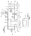
Fig. 1 das Prinzipschaltbild eines hydraulischen Antriebs gemäß einem bevorzugten Ausführungsbeispiel der Erfindung im Stillstand (unter Vorspannung), -
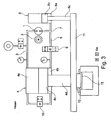
Fig. 2 das Prinzipschaltbild des hydraulischen Antriebs gemäßFig. 1 im "Eilgang" abwärts, -
Fig. 3 das Prinzipschaltbild des hydraulischen Antriebs gemäßFig. 1 im "Pressgang", -
Fig. 4 das Prinzipschaltbild des hydraulischen Antriebs gemäßFig. 1 in einer Re-Kompressionsphase und -
Fig. 5 das Prinzipschaltbild des hydraulischen Antriebs gemäßFig. 1 im "Eilgang" aufwärts (Rückzugsphase). - Wie aus sämtlichen Figuren zu entnehmen ist, hat der erfindungsgemäße hydraulische Antrieb eine Druckmittelquelle in Form einer drehzahlvariabel angetriebenen Hydromaschine 1 als Pumpe, die hierfür an einen Elektromotor 2 mechanisch angeschlossen ist. Die Hydromaschine 1 ist an ihren zwei Druckanschlüssen an ein hydraulisches Druckleitungssystem angeschlossen, welches einen geschlossenen Hydraulikdruckkreis bildet.
- Im Konkreten ist an einen ersten Druckanschluss der Hydromaschine 1 eine erste Verbindungsleitung 3 angeschlossen, die direkt zu einer kolbenseitigen Druckkammer 4a eines Hauptzylinders 4 führt. An den zweiten Druckanschluss der Hydromaschine 1 ist eine zweite Leitung 5 angeschlossen, die über ein Ventil 6 mit einer kolbenstangenseitigen Druckkammer 4b des Hauptzylinders 4 (nachfolgend als Ringkammer 4b bezeichnet) verbunden ist. Das Ventil 6 ist vorliegend als ein Wegeventil und insbesondere als ein 3/2 Wege-Schaltventil ausgebildet mit einer ersten Schaltposition, in der lediglich eine Hydraulikfluidströmung aus der Ringkammer 4b des Hauptzylinders 4 in Richtung Hydromaschine 1 zugelassen wird, einer zweiten Schaltposition, in der eine Hydraulikfluidströmung in beide Richtungen möglich ist und einer dritten Schaltposition, in der die zweite Leitung 5 vollständig gesperrt ist.
- Zwischen der Hydromaschine 1 und dem vorstehend genannten Wege-Schaltventil 6 ist in die zweite Leitung 5 eine Abzweigung 7 eingesetzt, die zu einer kolbenstangenseitigen Druckkammer 8a eines Nebenzylinders 8 führt. Der Kolben 8b des Nebenzylinders 8 ist dabei in seinem Durchmesser deutlich kleiner als der Kolben 4c des Hauptzylinders 4, sodass der Hub des Nebenzylinders 8 bei vergleichbarem Volumenstrom des Hydraulikfluids größer ist als der Hub des Hauptzylinders 4. Ferner besitzen die Ringseiten der Zylinder 4, 8 idealer Weise in Summe die gleiche Fläche wie die Kolbenseite des Hauptzylinders 4.
- Schließlich ist eine Bypass- oder Kurzschlussleitung 9 vorgesehen, welche die Kolbenkammer 4a des Hauptzylinders 4 mit dessen Ringkammer 4b verbindet. In diese Bypassleitung 9 ist ein Kurzschlussventil 10 zwischengeschaltet, das vorliegend als Wegeschaltventil und vorzugsweise als 2/2 Wege Schaltventil ausgebildet ist. In einer ersten Schaltposition dieses Kurzschlussventils 10 ist die Bypassleitung 9 vollständig (d.h. in beide Richtungen) geöffnet, wobei in einer zweiten Schaltposition lediglich eine Fluidströmung aus der Ringkammer 4b in die Kolbenkammer 4a des Hauptzylinders 4 über die Bypassleitung 9 zugelassen ist.
- Im konkreten Ausführungsbeispiel der Erfindung ist der hydraulische Antrieb mit vorstehendem Aufbau in einer Presse eingebaut. Hierfür sind die Kolbenstange 4d des Hauptzylinders 4 wie auch die Kolbenstange 8c des Nebenzylinders 8 mit einem verschiebbar gelagerten Pressstempel 11 verbunden an dem ein Presswerkzeug 12 oder ein Stanzwerkzeug befestigt ist.
- Grundsätzlich hat das Hydraulikdrucksystem gemäß der Erfindung auch zahlreiche Sicherungseinrichtungen zur Vermeidung von Überdruckzuständen oder von unbeabsichtigem Absinken des Pressstempels 11, die jedoch in den Figuren nicht im Detail dargestellt sind. So kann die Ringkammer 8a des Nebenzylinders 8 über zwei in Serie geschaltete, überwachte Sitzventile (nicht gezeigt) gesichert sein. Dadurch kann ein Absinken des oberen Presswerkzeugs 12 sicher verhindert werden. Zudem kann die Kolbenkammer 4a des Hauptzylinders 4 gegen eine unbeabsichtigte Druckbeaufschlagung abgesichert sein. Erfolgen kann dies durch die gezeigten Wegeventile 6, 10 selbst, oder aber durch eine überwachte Freigabe des elektrischen Antriebsmotors 2 der Hydromaschine 1.
- Um Leckageverluste im System auszugleichen, ist an die erste Druckleitung 3 zwischen der Hydromaschine 1 und der Kolbenkammer 4a des Hauptzylinders 4 ein Druckspeicher 13 über ein Ventil 14 angeschlossen. Dieses Ventil 14 wird durch ein Wegeventil, vorzugsweise ein 2/2 Wege Schaltventil bereitgestellt, mit einer ersten Schaltposition, in der die Verbindung zwischen der externen Druckquelle 13 und der ersten Druckleitung 3 vollständig freigegeben ist und einer zweiten Schaltposition, in der lediglich eine Fluidströmung aus der externen Druckquelle 13 in die erste Druckleitung 3 zugelassen wird.
- Im Betriebszustand des hydraulischen Antriebs gemäß der Erfindung ist zumindest die kolbenseitige Druckkammer 4a des Hauptzylinders 4 ständig über die Druckmittelquelle mit einem vorbestimmten etwa konstanten (insbesondere geregelten) Hydraulikdruck beaufschlagt. Die Bewegung beider Zylinder 4, 8 wird dabei durch Umfördern von Druckmittel in dem geschlossenen Druckkreis mittels der drehzahlvariabel angetriebenen Hydromaschine 1 gesteuert.
- Maßgeblich für die Steuerung des Bewegungsablaufs beider Zylinder 4, 8 ist die Zufuhr oder Abfuhr von Druckmittel aus den jeweiligen Ringkammern 4b, 8a über die drehzahlvariabel angetriebene Hydromaschine 1, wobei der komplette Bewegungsablauf des Arbeitshubs der Presse unter Beteiligung beider Zylinder mittels der Ventile 6, 10 und der drehzahlvariabel angetriebenen (Konstant-)Pumpe gesteuert werden kann.
- Die Funktionsweise des erfindungsgemäßen hydraulischen Antriebs lässt sich anhand der anliegenden Figuren wie folgt beschreiben:
- Gemäß der
Fig. 1 befinden sich bei Stillstand des hydraulischen Antriebs (in zurückgezogener Stellung des Pressstempels 11) das Wegeschaltventil 6 in jener Schaltposition, in der nur eine Fluidströmung aus der Ringkammer 4b des Hauptzylinders 4 zugelassen ist und das Kurzschlussventil 10 in der Schaltposition, in der die Bypassleitung 9 vollständig geöffnet ist. Der elektrische Antriebsmotor 2 der Hydromaschine 1 ist ferner abgeschaltet. - In diesem (statischen) Zustand wird das Gewicht des Pressstempels 11 durch den Druck innerhalb der Kolbenkammer 8a des Nebenzylinders 8 abgestützt, während in der Ring- und Kolbenkammer 4a, 4b des Hauptzylinders 4 über das Kurzschlussventil 10 Druckausgleich herrscht.
- Um aus diesem (statischen) Zustand in den Eilgang abwärts zu kommen, wird gemäß der
Fig. 2 das Ventil 6 in die vollständige Sperrposition geschaltet und die Hydromaschine 1 angetrieben. Hierdurch wird Druckmittel ausschließlich aus der Ringkammer 8a des Nebenzylinders 8 über die Leitung 5 abgesaugt und in die Kolbenkammer 4a des Hauptkolbens 4 abgegeben. Gleichzeitig bleibt der Druckausgleich zwischen den Hauptzylinderkammern 4a, 4b über das immer noch vollständig offene Kurzschlussventil 10 erhalten. - Da der Nebenzylinder 8 kleiner ist als der Hauptzylinder 4 und die Pumpe 1 nur auf das Volumen der Ringseite des Nebenzylinders 8 wirkt, erfolgt die Abwärtsbewegung (und später auch die Rückziehbewegung) des Pressstempels 11 bei vorbestimmtem Volumenstrom bei einer relativ hohen Geschwindigkeit, auch dann, wenn die Hydromaschine 1 mit einer kleinen Kapazität ausgelegt ist. Darüber hinaus kann durch kurzzeitige Überlastung des elektrischen Antriebsmotors 2 (zulässig) die Geschwindigkeit aber auch die spätere Presskraft weiter erhöht werden.
- Sobald das Presswerkzeug 12 ein zu bearbeitendes Werkstück 15 erreicht hat, schaltet das Kurzschlussventil 10 in die Schaltposition in der nur eine Strömung aus der Ringkammer 4b des Hauptzylinders 4 zugelassen ist und das Ventil 6 in die Schaltposition, in der eine Fluidströmung aus de Ringkammer 4b zur Hydromaschine 1 zugelassen wird. In diesem Zustand gemäß der
Fig. 3 wird nunmehr auch der Druck innerhalb der Ringkammer 4b durch die Hydromaschine 1 abgebaut, da kein Druckausgleich zwischen den Hauptzylinderkammern 4a, 4b über das Kurzschlussventil 10 mehr stattfindet, wohingegen der Druck innerhalb der Kolbenkammer 4a des Hauptzylinders 4 beibehalten bzw. erhöht wird. D.h., anstatt einer erheblichen Kompression der Kolbenseite des Hauptzylinders 4, wird die eigentliche Presskraft durch Druckentspannung der Ringseiten der Zylinder 4, 8 erzeugt. Da kein Druckausgleich zwischen den Hauptzylinderkammern 4a, 4b mehr erfolgt, nimmt ferner die fortlaufende Pressbewegung des Hauptzylinders 4 bei gleich bleibendem Volumenstrom eine zur Absenkbewegung deutlich geringere Geschwindigkeit an als beim vorherigen Eilgang. - Zum Beenden des Pressvorgangs wird das Ventil 6 in eine Schaltposition gemäß der
Fig. 4 gebracht, wonach eine Fluidströmung innerhalb der Verbindungsleitung 5 in beide Richtungen, d.h. aus und zu der Ringkammer 4b des Hauptzylinders 4 ermöglicht ist. In diesem Fall erfolgt ein Druckausgleich zwischen den Hauptzylinderkammern 4a, 4b und der Ringkammer 8a des Nebenzylinders 8 über die Verbindungsleitung 5 und die Abzweigung 7, wobei gleichzeitig Energie über den elektrischen Antriebsmotor 2 zurückgewonnen werden kann. - Schließlich kann der Pressstempel 11 zurückgezogen werden, indem wie in
Fig. 5 dargestellt ist, das Ventil 6 in die Schaltposition gebracht wird, in der nur eine Strömung aus dem Ringraum 4a des Hauptzylinders 4 zugelassen ist und das Kurzschlussventil 10 in die Schaltposition geschaltet wird, in der die Bypassleitung 9 vollständig (in beide Richtungen) geöffnet ist. - Wird in diesem Zustand die Hydromaschine 1 angetrieben, um Druckmittel aus der Kolbenkammer 4a des Hauptzylinders 4 abzuziehen, wird das abgezogene Druckmittel bei vollständigem Druckausgleich der beiden Hauptzylinderkammern 4a, 4b in die Ringkammer 8a des Nebenzylinders 8 gedrückt, der den Pressstempel 11 mit hoher Geschwindigkeit wieder zurückzieht.
- Bei dem vorstehend beschriebenen hydraulischen Antrieb kann die Hydromaschine 1 an einen Ventilblock (nicht weiter dargestellt) angeflanscht sein, welcher die Funktions- bzw. Sicherheitsventile des Antriebs enthält. An diesen kann wiederum der Elektromotor zum Betrieb der Pumpe angebaut sein. Diese Einheit kann wiederum auf einem Hydrozylinder aufgebaut sein, wodurch eine besonders kompakte Anstriebsachse zur Verfügung steht.
-
1 Hydromaschine 2 Servomotor (drehzahlvariabel) 3 erste Verbindungsleitung 4 Hauptzylinder 4a Kolbenkammer 4b Ringkammer 4c Hauptzylinderkolben 4d Kolbenstange 5 zweite Druckleitung 6 Ventil 7 Abzweigung 8 Nebenzylinder 8a Ringkammer 8b Nebenzylinderkolben 8c Kolbenstange 9 Bypassleitung 10 Kurzschlussventil 11 Pressstempel 12 Presswerkzeug 13 Druckspeicher 14 Ventil 15 Werkstück
Claims (7)
- Hydraulischer Antrieb mit einer von einem elektrischen Antriebsmotor (2) drehzahlvariabel angesteuerten Hydromaschine (1), einem Hauptzylinder (4) zur Durchführung eines kraftaufbauenden Bewegungsablaufs sowie einem Nebenzylinder (8) zur Durchführung eines schnellen Bewegungsablaufs, dadurch gekennzeichnet, dass im Betrieb zumindest eine Kolbenseite des Hauptzylinders (4) mit einem von einer externen Druckquelle (13) und/oder von der vom Antriebsmotor (2) mechanisch angesteuerten Hydromaschine (1) an deren einem Druckanschluss aufgebauten vorbestimmten Permanentdruck beaufschlagt ist, wobei die Hydromaschine (1) im Betrieb ferner durch ausgewähltes Umfördern von Druckmittel in einem geschlossenen Kreis, in den die Hydromaschine (1) zwischengeschaltet ist, eine Hubbewegung des Hauptzylinders (4) und des Nebenzylinders (8) nach jeweils einem der zwei Bewegungsabläufe bewirkt.
- Hydraulischer Antrieb nach Anspruch 1, dadurch gekennzeichnet, dass der andere Druckanschluss der Hydromaschine (1) an eine kolbenstangenseitige Ringkammer (4b) des Hauptzylinders (4) und an eine kolbenstangenseitige Ringkammer (8a) des Nebenzylinders (8) angeschlossen ist.
- Hydraulischer Antrieb nach Anspruch 2, dadurch gekennzeichnet, dass in einer Verbindungsleitung (5) des geschlossenen Kreises zwischen der Hydromaschine (1) und der Hauptzylinderringkammer (4b) ein Ventil, vorzugsweise ein Wegeschaltventil (6) zwischengeschaltet ist.
- Hydraulischer Antrieb nach Anspruch 3, dadurch gekennzeichnet, dass das Ventil (6) ein 3/2 Wege-Schaltventil ist mit einer ersten Schaltposition, in der lediglich eine Hydraulikfluidströmung aus der Hauptzylinderringkammer (4b) in Richtung Hydromaschine (1) zugelassen wird, einer zweiten Schaltposition, in der eine Hydraulikfluidströmung in beide Richtungen ermöglicht ist und einer dritten Schaltposition, in der die Verbindungsleitung (5) vollständig gesperrt ist.
- Hydraulischer Antrieb nach Anspruch 3 oder 4, gekennzeichnet durch eine Bypassleitung des geschlossenen Kreises, welche die Hauptzylinderkolbenkammer (4a) mit der Hauptzylinderringkammer (4b verbindet und in die ein Kurzschlussventil (10) zwischengeschaltet ist.
- Hydraulischer Antrieb nach Anspruch 5, dadurch gekennzeichnet, dass das Kurzschlussventil (10) ein 2/2 Wege-Schaltventil ist, das in einer ersten Schaltposition die Bypassleitung (9) vollständig öffnet und in einer zweiten Schaltposition lediglich eine Fluidströmung aus der Ringkammer (4b) in die Kolbenkammer (4a) des Hauptzylinders (4) über die Bypassleitung (9) zulässt.
- Hydraulischer Antrieb nach einem der vorstehenden Ansprüche, dadurch gekennzeichnet, dass die Kolbenstangenseiten (4b, 8a) beider Zylinder (4, 8) in Summe die gleiche Fläche besitzen, wie die Kolbenseite (4a) des Hauptzylinders (4).
Applications Claiming Priority (2)
| Application Number | Priority Date | Filing Date | Title |
|---|---|---|---|
| DE200910043034 DE102009043034A1 (de) | 2009-09-25 | 2009-09-25 | Vorgespannter hydraulischer Antrieb mit drehzahlvariabler Pumpe |
| PCT/EP2010/004578 WO2011035828A1 (de) | 2009-09-25 | 2010-07-27 | Vorgespannter hydraulischer antrieb mit drehzahlvariabler pumpe |
Publications (2)
| Publication Number | Publication Date |
|---|---|
| EP2480405A1 EP2480405A1 (de) | 2012-08-01 |
| EP2480405B1 true EP2480405B1 (de) | 2013-06-19 |
Family
ID=43087109
Family Applications (1)
| Application Number | Title | Priority Date | Filing Date |
|---|---|---|---|
| EP10740535.9A Revoked EP2480405B1 (de) | 2009-09-25 | 2010-07-27 | Vorgespannter hydraulischer antrieb mit drehzahlvariabler pumpe |
Country Status (5)
| Country | Link |
|---|---|
| EP (1) | EP2480405B1 (de) |
| CN (1) | CN102612430B (de) |
| DE (1) | DE102009043034A1 (de) |
| TW (1) | TWI519717B (de) |
| WO (1) | WO2011035828A1 (de) |
Cited By (3)
| Publication number | Priority date | Publication date | Assignee | Title |
|---|---|---|---|---|
| WO2015185644A1 (de) | 2014-06-04 | 2015-12-10 | Moog Gmbh | Hydrauliksystem |
| DE102017202131A1 (de) | 2017-02-10 | 2018-08-16 | Siemens Aktiengesellschaft | Piezohydraulischer Aktor und Verfahren zum Betreiben eines solchen piezohydraulischen Aktors |
| WO2025119512A1 (en) | 2023-12-04 | 2025-06-12 | Moog Italiana S.R.L. | Drive unit |
Families Citing this family (15)
| Publication number | Priority date | Publication date | Assignee | Title |
|---|---|---|---|---|
| EP2637852B1 (de) | 2010-11-11 | 2017-01-18 | Robert Bosch GmbH | Hydraulische achse |
| DE102012020581A1 (de) | 2012-10-22 | 2014-04-24 | Robert Bosch Gmbh | Hydraulische Schaltung für eine hydraulische Achse und eine hydraulische Achse |
| DE102013227053B4 (de) | 2013-12-23 | 2023-04-20 | Robert Bosch Gmbh | Hydraulische Achse |
| DE102014226236A1 (de) * | 2014-09-29 | 2016-03-31 | Robert Bosch Gmbh | Hydraulische Schaltung und Maschine mit einer hydraulischen Schaltung |
| DE102014219734A1 (de) * | 2014-09-30 | 2016-03-31 | Robert Bosch Gmbh | Hydraulische Schaltung zur Druckmittelversorgung eines Differentialzylinders |
| EP3109488B1 (de) | 2015-06-25 | 2017-12-13 | MOOG GmbH | Betriebssicherer hydraulischer antrieb |
| DE102015011209B4 (de) * | 2015-08-26 | 2021-03-18 | Horst Baltschun | Hydraulische Presse |
| DE102015225436A1 (de) | 2015-12-16 | 2017-06-22 | Robert Bosch Gmbh | Ventilblock, Zylinder, Kompaktachse und Kompaktachsen-Baukasten |
| DE102016113882A1 (de) * | 2016-07-27 | 2018-02-01 | Moog Gmbh | Elektro-hydrostatisches Antriebssystem |
| EP3609692B1 (de) * | 2017-08-01 | 2021-07-21 | Moog GmbH | Vorrichtung zur steuerung der umschaltung von hydraulikzylindern |
| CN108590602B (zh) * | 2018-04-14 | 2020-11-06 | 嘉兴市国龙石油化工股份有限公司 | 一种用于石油开采设备的自动加压装置 |
| DE102018113910A1 (de) | 2018-06-11 | 2019-12-12 | Moog Gmbh | Strangpresse mit elektrohydrostatischen Steuersystem |
| DE102018120000A1 (de) * | 2018-08-16 | 2020-02-20 | Moog Gmbh | Elektrohydrostatisches Aktuatorsystem mit Nachsaugbehälter |
| DE102019105449A1 (de) * | 2019-03-04 | 2020-09-10 | Wacker Neuson Linz Gmbh | Linearantrieb mit geschlossenem Hydraulikkreislauf |
| US12038027B2 (en) | 2020-02-14 | 2024-07-16 | Metismotion Gmbh | Actuator device and method for operating an actuator device of this type |
Family Cites Families (6)
| Publication number | Priority date | Publication date | Assignee | Title |
|---|---|---|---|---|
| DE3640236A1 (de) * | 1986-11-25 | 1988-06-01 | Rexroth Mannesmann Gmbh | Anordnung zum erzeugen hoher hydraulischer druecke |
| JPH029988A (ja) * | 1988-06-28 | 1990-01-12 | Daikin Ind Ltd | 流体機械の油戻し装置 |
| DE4308344A1 (de) * | 1993-03-16 | 1994-09-22 | Mueller Weingarten Maschf | Verfahren zur Regelung des Antriebs einer hydraulischen Presse und Vorrichtung zur Durchführung des Verfahrens |
| DE4436666A1 (de) * | 1994-10-13 | 1996-04-18 | Rexroth Mannesmann Gmbh | Hydraulisches Antriebssystem für eine Presse |
| JPH10141310A (ja) * | 1996-11-13 | 1998-05-26 | Komatsu Ltd | 圧油供給装置 |
| JP2006316800A (ja) * | 2005-05-10 | 2006-11-24 | Osaka Jack Seisakusho:Kk | ジャッキ装置 |
-
2009
- 2009-09-25 DE DE200910043034 patent/DE102009043034A1/de not_active Withdrawn
-
2010
- 2010-07-27 EP EP10740535.9A patent/EP2480405B1/de not_active Revoked
- 2010-07-27 WO PCT/EP2010/004578 patent/WO2011035828A1/de not_active Ceased
- 2010-07-27 CN CN201080042771.7A patent/CN102612430B/zh active Active
- 2010-09-23 TW TW099132124A patent/TWI519717B/zh not_active IP Right Cessation
Cited By (3)
| Publication number | Priority date | Publication date | Assignee | Title |
|---|---|---|---|---|
| WO2015185644A1 (de) | 2014-06-04 | 2015-12-10 | Moog Gmbh | Hydrauliksystem |
| DE102017202131A1 (de) | 2017-02-10 | 2018-08-16 | Siemens Aktiengesellschaft | Piezohydraulischer Aktor und Verfahren zum Betreiben eines solchen piezohydraulischen Aktors |
| WO2025119512A1 (en) | 2023-12-04 | 2025-06-12 | Moog Italiana S.R.L. | Drive unit |
Also Published As
| Publication number | Publication date |
|---|---|
| CN102612430A (zh) | 2012-07-25 |
| TWI519717B (zh) | 2016-02-01 |
| WO2011035828A1 (de) | 2011-03-31 |
| DE102009043034A1 (de) | 2011-03-31 |
| TW201115034A (en) | 2011-05-01 |
| CN102612430B (zh) | 2016-04-27 |
| EP2480405A1 (de) | 2012-08-01 |
Similar Documents
| Publication | Publication Date | Title |
|---|---|---|
| EP2480405B1 (de) | Vorgespannter hydraulischer antrieb mit drehzahlvariabler pumpe | |
| DE102011000473B4 (de) | Pressmaschine und Verfahren zum Pressen von Werkstücken | |
| EP0615837B1 (de) | Verfahren zur Regelung des Antriebs einer hydraulischen Presse und Vorrichtung zur Durchführung des Verfahrens | |
| EP2722165B1 (de) | Hydraulische schaltung für eine hydraulische achse und eine hydraulische achse | |
| EP0972631B1 (de) | Hydraulischer Antrieb für eine Presse | |
| EP3174650B1 (de) | Stanzvorrichtung und verfahren zum stanzen eines werkstücks | |
| DE102012015118B3 (de) | Maschinenpresse | |
| WO2002024441A1 (de) | Steuervorrichtung für eine hydraulische presse sowie verfahren zu deren betrieb | |
| EP3880975B1 (de) | Elektrohydrostatisches aktuatorsystem | |
| EP2420681B1 (de) | Hydraulischer Linearantrieb | |
| DE102006058630B4 (de) | Elektrohydraulische Pressenhaupt- oder Nebenantriebseinrichtung, insbesondere elektrohydraulischer Ziehkissenantrieb | |
| EP2846942B1 (de) | Hydraulische strangpresse sowie verfahren zum betrieb einer hydraulischen strangpresse | |
| EP2511023B1 (de) | Hydraulisch betriebenes Setzgerät mit einem Hydraulikaggregat und ein Fügeverfahren zum Verbinden von mindestens zwei Bauteilen | |
| EP3115190B1 (de) | Vorrichtung und verfahren zum steuern des hauptantriebs einer feinschneidpresse | |
| EP1706648A1 (de) | Antriebsvorrichtung | |
| DE102013007148B4 (de) | Hydraulischer Pressantrieb mit Energierückspeisung | |
| EP1924773A1 (de) | Steuervorrichtung und steuerverfahren für eine kolben-zylinder-anordnung | |
| DE102016007266A1 (de) | Vorrichtung zur direkten Rekuperation von hydraulischer Energie mittels eines einfachwirkenden Hydraulikzylinders | |
| DE10339004B4 (de) | Hydraulische Presse | |
| DE102004006126A1 (de) | Presse mit verriegeltem Stößel | |
| DE4446580A1 (de) | Doppelpresse | |
| EP0559651B1 (de) | Hydraulisch angetriebene maschine mit zwei antriebszylindern | |
| EP2114587B1 (de) | Umformpresse mit im schiebetisch integrierter ziehkissenfunktionalität | |
| WO1999054123A1 (de) | Verfahren zum betrieb einer hydraulischen presse | |
| DE102024113217A1 (de) | Antriebseinheit |
Legal Events
| Date | Code | Title | Description |
|---|---|---|---|
| PUAI | Public reference made under article 153(3) epc to a published international application that has entered the european phase |
Free format text: ORIGINAL CODE: 0009012 |
|
| 17P | Request for examination filed |
Effective date: 20120425 |
|
| AK | Designated contracting states |
Kind code of ref document: A1 Designated state(s): AL AT BE BG CH CY CZ DE DK EE ES FI FR GB GR HR HU IE IS IT LI LT LU LV MC MK MT NL NO PL PT RO SE SI SK SM TR |
|
| DAX | Request for extension of the european patent (deleted) | ||
| GRAP | Despatch of communication of intention to grant a patent |
Free format text: ORIGINAL CODE: EPIDOSNIGR1 |
|
| GRAS | Grant fee paid |
Free format text: ORIGINAL CODE: EPIDOSNIGR3 |
|
| GRAA | (expected) grant |
Free format text: ORIGINAL CODE: 0009210 |
|
| AK | Designated contracting states |
Kind code of ref document: B1 Designated state(s): AL AT BE BG CH CY CZ DE DK EE ES FI FR GB GR HR HU IE IS IT LI LT LU LV MC MK MT NL NO PL PT RO SE SI SK SM TR |
|
| REG | Reference to a national code |
Ref country code: GB Ref legal event code: FG4D Free format text: NOT ENGLISH |
|
| REG | Reference to a national code |
Ref country code: CH Ref legal event code: EP |
|
| REG | Reference to a national code |
Ref country code: AT Ref legal event code: REF Ref document number: 617405 Country of ref document: AT Kind code of ref document: T Effective date: 20130715 |
|
| REG | Reference to a national code |
Ref country code: IE Ref legal event code: FG4D Free format text: LANGUAGE OF EP DOCUMENT: GERMAN |
|
| REG | Reference to a national code |
Ref country code: DE Ref legal event code: R096 Ref document number: 502010003754 Country of ref document: DE Effective date: 20130814 |
|
| PG25 | Lapsed in a contracting state [announced via postgrant information from national office to epo] |
Ref country code: SI Free format text: LAPSE BECAUSE OF FAILURE TO SUBMIT A TRANSLATION OF THE DESCRIPTION OR TO PAY THE FEE WITHIN THE PRESCRIBED TIME-LIMIT Effective date: 20130619 Ref country code: FI Free format text: LAPSE BECAUSE OF FAILURE TO SUBMIT A TRANSLATION OF THE DESCRIPTION OR TO PAY THE FEE WITHIN THE PRESCRIBED TIME-LIMIT Effective date: 20130619 Ref country code: NO Free format text: LAPSE BECAUSE OF FAILURE TO SUBMIT A TRANSLATION OF THE DESCRIPTION OR TO PAY THE FEE WITHIN THE PRESCRIBED TIME-LIMIT Effective date: 20130919 Ref country code: ES Free format text: LAPSE BECAUSE OF FAILURE TO SUBMIT A TRANSLATION OF THE DESCRIPTION OR TO PAY THE FEE WITHIN THE PRESCRIBED TIME-LIMIT Effective date: 20130930 Ref country code: GR Free format text: LAPSE BECAUSE OF FAILURE TO SUBMIT A TRANSLATION OF THE DESCRIPTION OR TO PAY THE FEE WITHIN THE PRESCRIBED TIME-LIMIT Effective date: 20130920 Ref country code: SE Free format text: LAPSE BECAUSE OF FAILURE TO SUBMIT A TRANSLATION OF THE DESCRIPTION OR TO PAY THE FEE WITHIN THE PRESCRIBED TIME-LIMIT Effective date: 20130619 Ref country code: LT Free format text: LAPSE BECAUSE OF FAILURE TO SUBMIT A TRANSLATION OF THE DESCRIPTION OR TO PAY THE FEE WITHIN THE PRESCRIBED TIME-LIMIT Effective date: 20130619 |
|
| REG | Reference to a national code |
Ref country code: LT Ref legal event code: MG4D |
|
| PG25 | Lapsed in a contracting state [announced via postgrant information from national office to epo] |
Ref country code: BG Free format text: LAPSE BECAUSE OF FAILURE TO SUBMIT A TRANSLATION OF THE DESCRIPTION OR TO PAY THE FEE WITHIN THE PRESCRIBED TIME-LIMIT Effective date: 20130919 Ref country code: HR Free format text: LAPSE BECAUSE OF FAILURE TO SUBMIT A TRANSLATION OF THE DESCRIPTION OR TO PAY THE FEE WITHIN THE PRESCRIBED TIME-LIMIT Effective date: 20130619 |
|
| REG | Reference to a national code |
Ref country code: NL Ref legal event code: VDEP Effective date: 20130619 |
|
| PG25 | Lapsed in a contracting state [announced via postgrant information from national office to epo] |
Ref country code: LV Free format text: LAPSE BECAUSE OF FAILURE TO SUBMIT A TRANSLATION OF THE DESCRIPTION OR TO PAY THE FEE WITHIN THE PRESCRIBED TIME-LIMIT Effective date: 20130619 |
|
| BERE | Be: lapsed |
Owner name: ROBERT BOSCH G.M.B.H. Effective date: 20130731 |
|
| PG25 | Lapsed in a contracting state [announced via postgrant information from national office to epo] |
Ref country code: PT Free format text: LAPSE BECAUSE OF FAILURE TO SUBMIT A TRANSLATION OF THE DESCRIPTION OR TO PAY THE FEE WITHIN THE PRESCRIBED TIME-LIMIT Effective date: 20131021 Ref country code: IS Free format text: LAPSE BECAUSE OF FAILURE TO SUBMIT A TRANSLATION OF THE DESCRIPTION OR TO PAY THE FEE WITHIN THE PRESCRIBED TIME-LIMIT Effective date: 20131019 Ref country code: EE Free format text: LAPSE BECAUSE OF FAILURE TO SUBMIT A TRANSLATION OF THE DESCRIPTION OR TO PAY THE FEE WITHIN THE PRESCRIBED TIME-LIMIT Effective date: 20130619 Ref country code: CY Free format text: LAPSE BECAUSE OF FAILURE TO SUBMIT A TRANSLATION OF THE DESCRIPTION OR TO PAY THE FEE WITHIN THE PRESCRIBED TIME-LIMIT Effective date: 20130904 Ref country code: SK Free format text: LAPSE BECAUSE OF FAILURE TO SUBMIT A TRANSLATION OF THE DESCRIPTION OR TO PAY THE FEE WITHIN THE PRESCRIBED TIME-LIMIT Effective date: 20130619 Ref country code: CZ Free format text: LAPSE BECAUSE OF FAILURE TO SUBMIT A TRANSLATION OF THE DESCRIPTION OR TO PAY THE FEE WITHIN THE PRESCRIBED TIME-LIMIT Effective date: 20130619 |
|
| PG25 | Lapsed in a contracting state [announced via postgrant information from national office to epo] |
Ref country code: RO Free format text: LAPSE BECAUSE OF FAILURE TO SUBMIT A TRANSLATION OF THE DESCRIPTION OR TO PAY THE FEE WITHIN THE PRESCRIBED TIME-LIMIT Effective date: 20130619 Ref country code: PL Free format text: LAPSE BECAUSE OF FAILURE TO SUBMIT A TRANSLATION OF THE DESCRIPTION OR TO PAY THE FEE WITHIN THE PRESCRIBED TIME-LIMIT Effective date: 20130619 Ref country code: NL Free format text: LAPSE BECAUSE OF FAILURE TO SUBMIT A TRANSLATION OF THE DESCRIPTION OR TO PAY THE FEE WITHIN THE PRESCRIBED TIME-LIMIT Effective date: 20130619 |
|
| PLBI | Opposition filed |
Free format text: ORIGINAL CODE: 0009260 |
|
| PG25 | Lapsed in a contracting state [announced via postgrant information from national office to epo] |
Ref country code: CY Free format text: LAPSE BECAUSE OF FAILURE TO SUBMIT A TRANSLATION OF THE DESCRIPTION OR TO PAY THE FEE WITHIN THE PRESCRIBED TIME-LIMIT Effective date: 20130619 Ref country code: MC Free format text: LAPSE BECAUSE OF FAILURE TO SUBMIT A TRANSLATION OF THE DESCRIPTION OR TO PAY THE FEE WITHIN THE PRESCRIBED TIME-LIMIT Effective date: 20130619 |
|
| REG | Reference to a national code |
Ref country code: IE Ref legal event code: MM4A |
|
| REG | Reference to a national code |
Ref country code: FR Ref legal event code: ST Effective date: 20140331 |
|
| 26 | Opposition filed |
Opponent name: MOOG GMBH Effective date: 20140319 |
|
| PG25 | Lapsed in a contracting state [announced via postgrant information from national office to epo] |
Ref country code: BE Free format text: LAPSE BECAUSE OF NON-PAYMENT OF DUE FEES Effective date: 20130731 Ref country code: DK Free format text: LAPSE BECAUSE OF FAILURE TO SUBMIT A TRANSLATION OF THE DESCRIPTION OR TO PAY THE FEE WITHIN THE PRESCRIBED TIME-LIMIT Effective date: 20130619 |
|
| PLAX | Notice of opposition and request to file observation + time limit sent |
Free format text: ORIGINAL CODE: EPIDOSNOBS2 |
|
| PG25 | Lapsed in a contracting state [announced via postgrant information from national office to epo] |
Ref country code: FR Free format text: LAPSE BECAUSE OF NON-PAYMENT OF DUE FEES Effective date: 20130819 |
|
| REG | Reference to a national code |
Ref country code: DE Ref legal event code: R026 Ref document number: 502010003754 Country of ref document: DE Effective date: 20140319 |
|
| PG25 | Lapsed in a contracting state [announced via postgrant information from national office to epo] |
Ref country code: IE Free format text: LAPSE BECAUSE OF NON-PAYMENT OF DUE FEES Effective date: 20130727 |
|
| PLAF | Information modified related to communication of a notice of opposition and request to file observations + time limit |
Free format text: ORIGINAL CODE: EPIDOSCOBS2 |
|
| PLBB | Reply of patent proprietor to notice(s) of opposition received |
Free format text: ORIGINAL CODE: EPIDOSNOBS3 |
|
| REG | Reference to a national code |
Ref country code: CH Ref legal event code: PL |
|
| GBPC | Gb: european patent ceased through non-payment of renewal fee |
Effective date: 20140727 |
|
| PG25 | Lapsed in a contracting state [announced via postgrant information from national office to epo] |
Ref country code: LI Free format text: LAPSE BECAUSE OF NON-PAYMENT OF DUE FEES Effective date: 20140731 Ref country code: CH Free format text: LAPSE BECAUSE OF NON-PAYMENT OF DUE FEES Effective date: 20140731 |
|
| PLAB | Opposition data, opponent's data or that of the opponent's representative modified |
Free format text: ORIGINAL CODE: 0009299OPPO |
|
| PG25 | Lapsed in a contracting state [announced via postgrant information from national office to epo] |
Ref country code: GB Free format text: LAPSE BECAUSE OF NON-PAYMENT OF DUE FEES Effective date: 20140727 Ref country code: SM Free format text: LAPSE BECAUSE OF FAILURE TO SUBMIT A TRANSLATION OF THE DESCRIPTION OR TO PAY THE FEE WITHIN THE PRESCRIBED TIME-LIMIT Effective date: 20130619 |
|
| R26 | Opposition filed (corrected) |
Opponent name: MOOG GMBH Effective date: 20140319 |
|
| PG25 | Lapsed in a contracting state [announced via postgrant information from national office to epo] |
Ref country code: MT Free format text: LAPSE BECAUSE OF FAILURE TO SUBMIT A TRANSLATION OF THE DESCRIPTION OR TO PAY THE FEE WITHIN THE PRESCRIBED TIME-LIMIT Effective date: 20130619 Ref country code: TR Free format text: LAPSE BECAUSE OF FAILURE TO SUBMIT A TRANSLATION OF THE DESCRIPTION OR TO PAY THE FEE WITHIN THE PRESCRIBED TIME-LIMIT Effective date: 20130619 |
|
| PG25 | Lapsed in a contracting state [announced via postgrant information from national office to epo] |
Ref country code: HU Free format text: LAPSE BECAUSE OF FAILURE TO SUBMIT A TRANSLATION OF THE DESCRIPTION OR TO PAY THE FEE WITHIN THE PRESCRIBED TIME-LIMIT; INVALID AB INITIO Effective date: 20100727 Ref country code: MK Free format text: LAPSE BECAUSE OF FAILURE TO SUBMIT A TRANSLATION OF THE DESCRIPTION OR TO PAY THE FEE WITHIN THE PRESCRIBED TIME-LIMIT Effective date: 20130619 Ref country code: LU Free format text: LAPSE BECAUSE OF NON-PAYMENT OF DUE FEES Effective date: 20130727 |
|
| PLCK | Communication despatched that opposition was rejected |
Free format text: ORIGINAL CODE: EPIDOSNREJ1 |
|
| APBM | Appeal reference recorded |
Free format text: ORIGINAL CODE: EPIDOSNREFNO |
|
| APBP | Date of receipt of notice of appeal recorded |
Free format text: ORIGINAL CODE: EPIDOSNNOA2O |
|
| APAH | Appeal reference modified |
Free format text: ORIGINAL CODE: EPIDOSCREFNO |
|
| APBQ | Date of receipt of statement of grounds of appeal recorded |
Free format text: ORIGINAL CODE: EPIDOSNNOA3O |
|
| PG25 | Lapsed in a contracting state [announced via postgrant information from national office to epo] |
Ref country code: AL Free format text: LAPSE BECAUSE OF FAILURE TO SUBMIT A TRANSLATION OF THE DESCRIPTION OR TO PAY THE FEE WITHIN THE PRESCRIBED TIME-LIMIT Effective date: 20130619 |
|
| PLAB | Opposition data, opponent's data or that of the opponent's representative modified |
Free format text: ORIGINAL CODE: 0009299OPPO |
|
| R26 | Opposition filed (corrected) |
Opponent name: MOOG GMBH Effective date: 20140319 |
|
| RAP2 | Party data changed (patent owner data changed or rights of a patent transferred) |
Owner name: ROBERT BOSCH GMBH |
|
| PGFP | Annual fee paid to national office [announced via postgrant information from national office to epo] |
Ref country code: DE Payment date: 20200924 Year of fee payment: 11 |
|
| APBU | Appeal procedure closed |
Free format text: ORIGINAL CODE: EPIDOSNNOA9O |
|
| REG | Reference to a national code |
Ref country code: DE Ref legal event code: R064 Ref document number: 502010003754 Country of ref document: DE Ref country code: DE Ref legal event code: R103 Ref document number: 502010003754 Country of ref document: DE |
|
| PGFP | Annual fee paid to national office [announced via postgrant information from national office to epo] |
Ref country code: AT Payment date: 20200720 Year of fee payment: 11 Ref country code: IT Payment date: 20200731 Year of fee payment: 11 |
|
| RDAF | Communication despatched that patent is revoked |
Free format text: ORIGINAL CODE: EPIDOSNREV1 |
|
| RDAG | Patent revoked |
Free format text: ORIGINAL CODE: 0009271 |
|
| STAA | Information on the status of an ep patent application or granted ep patent |
Free format text: STATUS: PATENT REVOKED |
|
| REG | Reference to a national code |
Ref country code: FI Ref legal event code: MGE |
|
| 27W | Patent revoked |
Effective date: 20201123 |
|
| REG | Reference to a national code |
Ref country code: AT Ref legal event code: MA03 Ref document number: 617405 Country of ref document: AT Kind code of ref document: T Effective date: 20201123 |