EP2479437A2 - Motorverdichtersystem und -verfahren - Google Patents
Motorverdichtersystem und -verfahren Download PDFInfo
- Publication number
- EP2479437A2 EP2479437A2 EP11194569A EP11194569A EP2479437A2 EP 2479437 A2 EP2479437 A2 EP 2479437A2 EP 11194569 A EP11194569 A EP 11194569A EP 11194569 A EP11194569 A EP 11194569A EP 2479437 A2 EP2479437 A2 EP 2479437A2
- Authority
- EP
- European Patent Office
- Prior art keywords
- motor
- compressor
- cartridge
- gas
- common casing
- Prior art date
- Legal status (The legal status is an assumption and is not a legal conclusion. Google has not performed a legal analysis and makes no representation as to the accuracy of the status listed.)
- Withdrawn
Links
Images


Classifications
-
- F—MECHANICAL ENGINEERING; LIGHTING; HEATING; WEAPONS; BLASTING
- F04—POSITIVE - DISPLACEMENT MACHINES FOR LIQUIDS; PUMPS FOR LIQUIDS OR ELASTIC FLUIDS
- F04D—NON-POSITIVE-DISPLACEMENT PUMPS
- F04D25/00—Pumping installations or systems
- F04D25/02—Units comprising pumps and their driving means
- F04D25/06—Units comprising pumps and their driving means the pump being electrically driven
-
- F—MECHANICAL ENGINEERING; LIGHTING; HEATING; WEAPONS; BLASTING
- F04—POSITIVE - DISPLACEMENT MACHINES FOR LIQUIDS; PUMPS FOR LIQUIDS OR ELASTIC FLUIDS
- F04D—NON-POSITIVE-DISPLACEMENT PUMPS
- F04D17/00—Radial-flow pumps, e.g. centrifugal pumps; Helico-centrifugal pumps
- F04D17/08—Centrifugal pumps
- F04D17/10—Centrifugal pumps for compressing or evacuating
- F04D17/12—Multi-stage pumps
- F04D17/122—Multi-stage pumps the individual rotor discs being, one for each stage, on a common shaft and axially spaced, e.g. conventional centrifugal multi- stage compressors
-
- F—MECHANICAL ENGINEERING; LIGHTING; HEATING; WEAPONS; BLASTING
- F04—POSITIVE - DISPLACEMENT MACHINES FOR LIQUIDS; PUMPS FOR LIQUIDS OR ELASTIC FLUIDS
- F04D—NON-POSITIVE-DISPLACEMENT PUMPS
- F04D29/00—Details, component parts, or accessories
- F04D29/40—Casings; Connections of working fluid
- F04D29/42—Casings; Connections of working fluid for radial or helico-centrifugal pumps
- F04D29/4206—Casings; Connections of working fluid for radial or helico-centrifugal pumps especially adapted for elastic fluid pumps
-
- F—MECHANICAL ENGINEERING; LIGHTING; HEATING; WEAPONS; BLASTING
- F04—POSITIVE - DISPLACEMENT MACHINES FOR LIQUIDS; PUMPS FOR LIQUIDS OR ELASTIC FLUIDS
- F04D—NON-POSITIVE-DISPLACEMENT PUMPS
- F04D29/00—Details, component parts, or accessories
- F04D29/60—Mounting; Assembling; Disassembling
- F04D29/601—Mounting; Assembling; Disassembling specially adapted for elastic fluid pumps
-
- F—MECHANICAL ENGINEERING; LIGHTING; HEATING; WEAPONS; BLASTING
- F04—POSITIVE - DISPLACEMENT MACHINES FOR LIQUIDS; PUMPS FOR LIQUIDS OR ELASTIC FLUIDS
- F04D—NON-POSITIVE-DISPLACEMENT PUMPS
- F04D29/00—Details, component parts, or accessories
- F04D29/60—Mounting; Assembling; Disassembling
- F04D29/62—Mounting; Assembling; Disassembling of radial or helico-centrifugal pumps
- F04D29/624—Mounting; Assembling; Disassembling of radial or helico-centrifugal pumps especially adapted for elastic fluid pumps
-
- Y—GENERAL TAGGING OF NEW TECHNOLOGICAL DEVELOPMENTS; GENERAL TAGGING OF CROSS-SECTIONAL TECHNOLOGIES SPANNING OVER SEVERAL SECTIONS OF THE IPC; TECHNICAL SUBJECTS COVERED BY FORMER USPC CROSS-REFERENCE ART COLLECTIONS [XRACs] AND DIGESTS
- Y10—TECHNICAL SUBJECTS COVERED BY FORMER USPC
- Y10T—TECHNICAL SUBJECTS COVERED BY FORMER US CLASSIFICATION
- Y10T29/00—Metal working
- Y10T29/49—Method of mechanical manufacture
- Y10T29/49229—Prime mover or fluid pump making
- Y10T29/49236—Fluid pump or compressor making
- Y10T29/49238—Repairing, converting, servicing or salvaging
Definitions
- Embodiments of the subject matter disclosed herein generally relate to methods and systems and, more particularly, to mechanisms and techniques for efficiently providing a motor and a compressor in a single casing.
- booster pumps or compressors may be located at intervals along a liquid-products or gas pipeline to boost the pressure of the flowing gas or liquid to keep it moving toward its destination.
- Booster pumps or compressors may also be used in other pipelines to move gas or liquid to and through various processes associated with petrochemical exploration, refinement and transport.
- Examples of a booster compressor are an in-line centrifugal compressor and an axial compressor that are used to move gaseous petrochemicals or byproducts through pipelines.
- These pipeline boosters can be used upstream (during exploration and production), midstream (during processing, storage and transportation) or downstream (during natural gas/petrochemical refining, transmission and distribution) in a petrochemical process.
- centrifugal compressors use a rotating disk or impeller in a shaped housing to force the gas to the rim of the impeller, increasing the velocity of the gas.
- a diffuser (divergent duct) section converts the velocity energy to pressure energy.
- a standard casing size can house a different number of impellers to optimize performance in terms of efficiency, compression ratio and operating range.
- Compressor casings can be made of forged steel to maximize material strength and metallurgical stability. Vibration reduction may be provided by bearings positioned at both casing ends. Dry gas seals may be used to prevent gas leakage. Floating bushing oil seals may also be used.
- booster stations can be used to drive the booster pumps or compressors, including electric motors, gas turbines or other motors.
- a booster station may couple a turbine, operating as a gas generator, with a power turbine to drive the booster compressor.
- an electric motor may be used, especially in pipelines.
- Fig. 1 shows an exploded view of a conventional centrifugal compressor configured to be connected to an external electric motor, not showed in the drawing. Many of the parts of this centrifugal compressor have been removed from the figure for simplicity. Even so, it is noted the amount of parts that need to be assembled/disassembled when maintaining the compressor. The time a plant needs to be stopped for the maintenance or replacement of this type of machine is very long because it is necessary to disassembly the external tubings or connections from the compressor or motor before their removal.
- FIG. 1 An example of a turbomachine that reduces the assembly/disassembly time comparative with the machine shown in Fig. 1 is the turbomachine assembly 100 having a compressor cartridge 102 and a motor 104 connected to each other as shown in Figs. 2 and 3 .
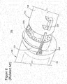
- This development includes housing an entire compressor in the compressor cartridge 102 and its electric motor 104 in a corresponding housing 103 that is designed for rapid installation/removal, as shown in Fig. 2 .
- a modular compressor assembly is designed such that the compressor cartridge 102 can be removed/installed in a compressor casing 106.
- the compressor cartridge 102 includes all the components of the compressor (e.g., impellers, bearings, seals, stationary flowpath components, etc.) within the cartridge. When installed, the modular compressor assembly is connected to the corresponding electric motor 104.
- a retractable cover 201 is operated, as shown in Figs. 3.
- Fig. 3 shows the retractable cover 201 covering a connection between the compressor cartridge 102 and the motor 104 while
- Fig. 2 shows the retractable cover 201 retracted to expose a connection 203.
- a mechanism 205 and 207 is noted for actuating the retractable cover 201.
- a motor compressor system in which the motor is configured to activate the compressor.
- the system includes a common casing; a motor cartridge housing a motor, the motor cartridge detachably placed inside the common casing; and a compressor cartridge housing a compressor detachably connected to the motor, the compressor cartridge detachably placed inside the common casing.
- a motor cartridge system that includes a motor cartridge configured to be detachably provided inside a common casing; and a motor housed within the motor cartridge and configured to be detachably connected to a compressor, the compressor configured to compress gas for transport in a gas pipeline.
- a motor compressor system in which a motor is configured to activate a compressor.
- the system includes a common casing; a motor cartridge housing the motor, the motor cartridge detachably provided inside the common casing; a compressor cartridge housing the compressor detachably connected to the motor, the compressor cartridge detachably provided inside the common casing; a mechanical connector connecting a motor shaft of the motor to a compressor shaft of the compressor within the common casing; magnetic bearings provided in the motor around the motor shaft; and a pipe configured to connect a downstream gas supply pipe or an upstream gas supply pipe connected to the common casing to a motor inlet duct of the motor cartridge so as to provide the gas to cool the motor.
- a method of repairing a system including a compressor cartridge having a compressor, the system also including a motor cartridge having a motor, the system configured to receive a gas, compress the gas, and eject the compressed gas.
- the method includes turning off the motor; closing or bypassing a gas flow through the compressor; disconnecting the motor from the compressor by disconnecting a mechanical joint connecting a motor shaft of the motor to a compressor shaft of the compressor; and disconnecting and removing the motor cartridge and/or the compressor cartridge from the common casing.
- the compressor cartridge and the motor cartridge are provided inside the common casing.
- the method includes receiving the gas into a motor compressor system from a pipeline duct at a first pressure, the motor compressor system including a compressor driven by a motor having magnetic bearings; compressing the gas with the compressor; and ejecting the compressed gas to an output pipeline at a second pressure higher that the first pressure.
- components of a motor are provided in a motor cartridge and components of a compressor are provided in a compressor cartridge to form a machine assembly.
- the compressor cartridge and the motor cartridge are independently from each other and connected to each other inside a common casing.
- the entire cartridge including the part may be removed from the common casing and another new cartridge may be slided back into the common casing for a fast restarting of the machine assembly.
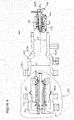
- Fig. 4 is a schematic of an embodiment of the invention.
- Fig. 4 shows a motor-compressor system 400 that includes a self-contained compressor cartridge 401 connectable to a self-contained motor cartridge 402.
- the compressor cartridge 401 may include a centrifugal compressor 405 and the motor cartridge 402 may include an electrical motor 407.
- the compressor cartridge 401 and the motor cartridge 402 are each configured to be connected to each other in a common casing 403.
- the common casing 403 is made of a single piece.
- both the compressor cartridge 401 and the motor cartridge 402 are configured to enter inside the common casing 403.
- the motor cartridge 402 may be bolted into the common casing 403 via bolts 4021 and 4022 that align with bolt holes 4031 and 4032, respectively. Two or more bolts may be used. Other methods of fastening may also be used.
- the compressor cartridge 401 is configured, for example, to completely enter inside the common casing 403.
- Shafts 409 and 410 of the compressor cartridge 401 and the motor cartridge 402 may be connected to each other by a Hirth connection 404A and a pin 404B.
- a Hirth connection is used to connect two pieces of a shaft together and is characterized by teeth that mesh together on the end faces of each half shaft.
- other connectors between the shafts of the centrifugal compressor cartridge 401 and the motor cartridge 402 may be used as long as the connection may be connected or disconnected without the need of maintenance personnel to enter inside the common casing 403.
- Such connections may be a magnetic connector or a flexible connector or a Hirth connection or a flange or others types of connections known in the art.
- the magnetic bearings 408 permit relative motion with very low friction and/or mechanical wear. Also, because magnetic bearings do not require lubricants, there is no risk of contamination from the lubricants, and there is no need to replenish said lubricants.
- the internal surfaces of the common casing 403 are preferably configured to permit the sliding of the motor cartridge 402 and the compressor cartridge 401 in opposite directions during the installation phase.
- Fig. 4 further shows the compressor shaft 409, the motor shaft 410, and shoulders 412A and B provided inside the common casing 403 for providing a stop position for the compressor and motor cartridges 401 and 402.
- a fan 414 is provided on the motor shaft 410 for driving a cooling gas coming from a duct 416 for cooling various parts of the motor cartridge 402.
- an internal diameter D1 of the common casing 403 corresponding to the motor cartridge 402 is larger than an internal diameter D2 of the common casing 403 corresponding to the compressor cartridge 401 or vice versa.
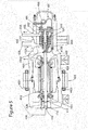
- Fig. 5 is a schematic of a compressor and a motor where the compressor cartridge 401 and the motor cartridge 402 are connected together and to the common casing 403. It is noted that by having the entire components of the compressor assembled in the compressor cartridge 401 and similar for the motor, the assembly and disassembly of the compressor and/or motor is quick as the entire cartridge is removed when a part has failed and a new cartridge may be inserted to quickly bring the plant or other facility back online.
- Fig. 5 shows further details of the motor compressor assembly 400.
- the motor cartridge 402 includes the motor shaft 410, magnetic bearings 420 configured to support the motor shaft 410, motor supports 422, a motor statoric part 424 and electric wirings 426 configured to provide electric power to the magnetic bearings 420 and other components of the motor cartridge.
- the motor cartridge may include a fan 414 attached to an end of the motor shaft 410 and configured to drive a cooling fluid from the duct 416 for cooling the motor.
- the fluid e.g., gas processed by the compressor cartridge 401, may be provided from a pipe 428 that is discussed later.
- the compressor cartridge includes the compressor shaft 409, magnetic bearings 430 configured to support the compressor shaft 409, a compressor bundle 432 (that may include the motor shaft and all the statoric diaphragms of the compressor), compressor diaphragms and diffusers 434, and compressor and bearings electric wiring 436 for supplying electrical power and/or data to various components of the compressor.
- This figure also shows how the compressor cartridge 401 and the motor cartridge enter inside the common casing 403, at least partially. Further, it is noted that both cartridges are configured to slide inside the common casing 403, for example, on wheels incorporated either in the common casing or in the cartridges.
- Fig. 5 shows that the motor cartridge 402 has its own external casing 402A that is configured to be attached to the common casing 403, for example, by bolts 4021 and 4022.
- the compressor cartridge (401) does not have an external casing as the entire compressor cartridge enters inside the common casing 403.
- a cover 401A is attached to the common casing 403 for closing the compressor cartridge 401 inside the casing.
- the compressor cartridge 401 is configured to have an inlet duct 450 that is configured to be connected to an upstream gas supply for providing the gas to an inlet 452 of the common casing 403 that feeds the compressor.
- the compressor cartridge 401 also has an outlet duct 454 that is configured to be connected to a downstream gas pipe.
- the outlet duct 454 is connected to an outlet 456 of the common casing 403 that receives the pressurized gas from the compressor.
- Pipe 428 may be connected to the inlet duct 450 or the outlet duct 454 for providing gas for cooling parts of the motor.
- a gas inlet 601 and a gas outlet 602 to the centrifugal compressor cartridge 401, as well as a gas port 603 to the motor cartridge 402 are shown.
- Gas port 603 provides compressed gas from the gas inlet 601 to the motor within the motor cartridge 402, where the gas expands thereby cooling the motor.
- a fan may be used as shown in Fig. 5 . The used gas is then returned to the compressor.
- the modular permanent magnetic motor compressor system shown in Figs. 4-6 include, but are not limited to, a) a shorter assembly/disassembly time; b) simplified coupling/decoupling of the compressor and motor; c) high level of standardization relative to the common casing; d) a smaller overall footprint of the system; and e) easier checking of the cartridges before assembly within the common casing. Also, unlike the related art described above, the modular permanent magnetic motor compressor system shown in Figs. 4-6 does not require a retractable port to facilitate connecting/disconnecting the cartridges, thus improving the structural integrity of the overall system.
- the turbomachine shown in Figs. 4-6 may operate with an inlet pressure range of 0 - 100 bar; outlet pressure range of 150-350 bar; unit power range of 2 - 10 Megawatts.
- the novel machine may be a multiple staging machine. Therefore, this machine may achieve different inlet or outlet pressure ranges or power ranges, e.g., extremely high output pressures greater than 350 bar. In other stage configurations, other pressure and horsepower ratings are possible.
- Fig. 7 is an exemplary embodiment of a gas compressing station 500.
- a gas pipeline 502 is coupled to a suction header 504 that enables gas flow into a gas compressor 506 powered by a motor 508. Gas entering compressor 506 is compressed and returned to pipeline 502 via a discharge header 510.
- a compressor inlet blocking valve 512 and an outlet blocking valve 514 facilitate control of compressor 506.
- a bypass header 516 includes a compressing station bypass blocking valve.
- a scrubber 518 is coupled in flow communication in suction header 504 to facilitate removing contaminants from the gas prior to gas introduction into compressor 506.
- compressor 506 and motor 508 are coupled to a common compressor/motor shaft 520.
- compressor 506 and motor 508 are connected by a Hirth connection and pin as shown in Figs. 4-6 .
- Suction header 504 channels gas to compressor 506 based on the relative positions of blocking valve 512, blocking valve 514, and blocking valve 516.
- blocking valves 512 and 514 are normally open to permit gas flow through station 500.
- Gas subsequently flows into compressor 506 and is compressed to a greater density and smaller volume.
- Motor 508 drives compressor 506 via common shaft 520. Compressed gas exits compressor 506 through discharge header 510.
- Valves 512 and 514 may be closed to isolate components, such as scrubber 518, compressor 506 and/or motor 508 during maintenance operations.
- Compressor 506 includes at least one stage of compression that increases a pressure of gas flowing therethrough.
- Compressor 506 includes: a housing with an inner surface and an outer surface, the inner surface defining a cooling plenum and a compressor intake plenum.
- There may also be a gas supply header coupled to the discharge header 510 such that a portion of the outlet gas flow is diverted to the motor 508 for cooling via expansion within the motor 508.
- the booster may include a gas supply header coupled to the suction header 504 such that a portion of the inlet gas flow stream upstream from the housing outer surface is diverted from the suction header and is channeled to the gas turbine as a fuel source.
- Fig. 8 is a flow chart of an exemplary method of the invention for repairing a motor compressor system including compressor cartridge including a centrifugal compressor, the system also including a motor cartridge including a motor, the system configured to receive a gas, compress the gas, and eject the compressed gas.
- the method includes: turning off the motor S801; bypassing the gas around the system S802; disconnecting the motor from the compressor S804 by disconnecting a hirth connector connecting the motor to the compressor S803; and disconnecting and removing the motor cartridge from the casing S805.
- the method may further include: reconnecting the motor within the motor cartridge (or a replacement motor in the same or difference motor cartridge) to the compressor S806; reconnecting the motor cartridge to the casing S807; resupplying the gas to the booster S808; and starting the motor S809.
- the same steps may be applied for connecting and/or disconnecting the compressor from
- Fig. 9 is a flow chart of an exemplary method of the invention for transporting gas through a pipeline.
- the method includes: receiving the gas into a motor compressor system from a first section of the pipeline at a first pressure S901, the system including a compressor driven by a motor having permanently magnetized bearings; compressing the gas with the centrifugal compressor S902; and ejecting the compressed gas to a second section of the pipeline at a second pressure higher that the first pressure S903.
- the system includes a common casing, a motor cartridge housing the motor and detachably connected to the common casing, and a compressor cartridge detachably connected to the common casing and housing the compressor, the compressor detachably connected to the motor via a hirth connector.
- the method may further include cooling the motor with the compressed gas S904.
- turbomachine is simple to upgrade while being part of the plant as the upgrade include replacing the compressor or motor cartridge of the novel machine with a new one in order to better match the changed plant needs.
- the disclosed exemplary embodiments provide a motor compressor system that includes self-contained compressor cartridge connectable to a self-contained motor cartridge, the compressor cartridge and the motor cartridge each configured to be installed in a common casing. It should be understood that this description is not intended to limit the invention. On the contrary, the exemplary embodiments are intended to cover alternatives, modifications and equivalents, which are included in the spirit and scope of the invention as defined by the appended claims. Further, in the detailed description of the exemplary embodiments, numerous specific details are set forth in order to provide a comprehensive understanding of the claimed invention. However, one skilled in the art would understand that various embodiments may be practiced without such specific details.
Landscapes
- Engineering & Computer Science (AREA)
- Mechanical Engineering (AREA)
- General Engineering & Computer Science (AREA)
- Structures Of Non-Positive Displacement Pumps (AREA)
- Compressor (AREA)
- Compressors, Vaccum Pumps And Other Relevant Systems (AREA)
- Control Of Electric Motors In General (AREA)
- Connection Of Motors, Electrical Generators, Mechanical Devices, And The Like (AREA)
- Manufacture Of Motors, Generators (AREA)
Applications Claiming Priority (1)
| Application Number | Priority Date | Filing Date | Title |
|---|---|---|---|
| ITMI2010A002466A IT1404373B1 (it) | 2010-12-30 | 2010-12-30 | Sistema compressore motore e metodo |
Publications (2)
| Publication Number | Publication Date |
|---|---|
| EP2479437A2 true EP2479437A2 (de) | 2012-07-25 |
| EP2479437A3 EP2479437A3 (de) | 2014-09-10 |
Family
ID=43737118
Family Applications (1)
| Application Number | Title | Priority Date | Filing Date |
|---|---|---|---|
| EP11194569.7A Withdrawn EP2479437A3 (de) | 2010-12-30 | 2011-12-20 | Motorverdichtersystem und -verfahren |
Country Status (6)
| Country | Link |
|---|---|
| US (1) | US20120171052A1 (de) |
| EP (1) | EP2479437A3 (de) |
| JP (1) | JP2012140943A (de) |
| CN (1) | CN102562518B (de) |
| IT (1) | IT1404373B1 (de) |
| RU (1) | RU2591745C2 (de) |
Cited By (4)
| Publication number | Priority date | Publication date | Assignee | Title |
|---|---|---|---|---|
| US10001143B2 (en) | 2013-02-26 | 2018-06-19 | Mitsubishi Heavy Industries Compressor Corporation | Method for assembling compressor, and bundle guide device |
| US10233945B2 (en) | 2013-02-27 | 2019-03-19 | Mitsubishi Heavy Industries Compressor Corporation | Compressor assembly method, and bundle guiding device |
| EP2761187B1 (de) * | 2011-09-27 | 2020-02-26 | Termodinamica SAS | Motorkompressoreinheit mit abnehmbarer kartusche |
| EP3929405A1 (de) * | 2020-06-22 | 2021-12-29 | Galileo Technologies Corporation | Mikroturbinenkraftanlage und verfahren zur montage |
Families Citing this family (7)
| Publication number | Priority date | Publication date | Assignee | Title |
|---|---|---|---|---|
| US20150260197A1 (en) * | 2012-10-16 | 2015-09-17 | Siemens Aktiengesellschaft | Weld-free pot volute casing |
| JP2015086710A (ja) * | 2013-10-28 | 2015-05-07 | 株式会社日立製作所 | ガスパイプライン用遠心圧縮機及びガスパイプライン |
| US10247194B2 (en) | 2016-06-10 | 2019-04-02 | John Crane Uk Ltd. | Reduced emission gas seal |
| US11796064B2 (en) | 2016-06-10 | 2023-10-24 | John Crane Uk Limited | Reduced emission gas seal |
| FR3096728B1 (fr) * | 2019-05-29 | 2022-01-28 | Thermodyn | Cartouche de compresseur, motocompresseur et procédé d’assemblage d’un tel motocompresseur |
| CN110374932A (zh) * | 2019-08-08 | 2019-10-25 | 西安陕鼓动力股份有限公司 | 压缩机芯包组件、推进装置及压缩机 |
| CN110360132A (zh) * | 2019-08-20 | 2019-10-22 | 西安陕鼓动力股份有限公司 | 集成式离心压缩机及其抽芯方法 |
Family Cites Families (16)
| Publication number | Priority date | Publication date | Assignee | Title |
|---|---|---|---|---|
| DE3729486C1 (de) * | 1987-09-03 | 1988-12-15 | Gutehoffnungshuette Man | Kompressoreinheit |
| JP2701057B2 (ja) * | 1988-02-08 | 1998-01-21 | 株式会社荏原製作所 | 弾性材料製全周流型水中モータポンプ |
| RU2109990C1 (ru) * | 1996-04-25 | 1998-04-27 | Юрий Иванович Журавлев | Центробежный компрессор |
| JP3799121B2 (ja) * | 1997-03-19 | 2006-07-19 | 株式会社 日立インダストリイズ | 2段遠心圧縮機 |
| GB2369935B (en) * | 2000-11-30 | 2005-07-20 | Richard Julius Gozdawa | Gas turbomachinery generator |
| AU2003224077A1 (en) * | 2003-04-15 | 2004-11-04 | Honeywell International Inc. | Electric motor cartridge for an electrically assisted turbocharger |
| NO323324B1 (no) * | 2003-07-02 | 2007-03-19 | Kvaerner Oilfield Prod As | Fremgangsmate for regulering at trykket i en undervannskompressormodul |
| US20090025386A1 (en) * | 2004-10-12 | 2009-01-29 | Peer Rumsby | Electrically assisted turbocharger |
| US7811068B2 (en) * | 2005-11-16 | 2010-10-12 | General Electric Company | Methods and apparatus for transporting natural gas through a pipeline |
| NO324811B1 (no) * | 2005-12-22 | 2007-12-10 | Norsk Hydro Produksjon As | Undervannspumpe |
| ITMI20060294A1 (it) * | 2006-02-17 | 2007-08-18 | Nuovo Pignone Spa | Motocompressore |
| US7508101B2 (en) * | 2006-02-24 | 2009-03-24 | General Electric Company | Methods and apparatus for using an electrical machine to transport fluids through a pipeline |
| CN201013629Y (zh) * | 2007-02-14 | 2008-01-30 | 佛山市顺德区新生源电器有限公司 | 一种双风道离心风机 |
| US20090196764A1 (en) * | 2008-02-04 | 2009-08-06 | Fogarty James M | High frequency electric-drive with multi-pole motor for gas pipeline and storage compression applications |
| IT1399171B1 (it) * | 2009-07-10 | 2013-04-11 | Nuovo Pignone Spa | Unita' di compressione ad alta pressione per fluidi di processo di impianti industriali e relativo metodo di funzionamento |
| IT1395718B1 (it) * | 2009-09-30 | 2012-10-19 | Nuovo Pignone Spa | Compressore a flusso assiale a sbalzo, reattore e metodo |
-
2010
- 2010-12-30 IT ITMI2010A002466A patent/IT1404373B1/it active
-
2011
- 2011-12-20 EP EP11194569.7A patent/EP2479437A3/de not_active Withdrawn
- 2011-12-22 JP JP2011281131A patent/JP2012140943A/ja active Pending
- 2011-12-28 RU RU2011153548/06A patent/RU2591745C2/ru not_active IP Right Cessation
- 2011-12-29 US US13/339,627 patent/US20120171052A1/en not_active Abandoned
- 2011-12-30 CN CN201110462723.XA patent/CN102562518B/zh not_active Expired - Fee Related
Non-Patent Citations (1)
| Title |
|---|
| None |
Cited By (4)
| Publication number | Priority date | Publication date | Assignee | Title |
|---|---|---|---|---|
| EP2761187B1 (de) * | 2011-09-27 | 2020-02-26 | Termodinamica SAS | Motorkompressoreinheit mit abnehmbarer kartusche |
| US10001143B2 (en) | 2013-02-26 | 2018-06-19 | Mitsubishi Heavy Industries Compressor Corporation | Method for assembling compressor, and bundle guide device |
| US10233945B2 (en) | 2013-02-27 | 2019-03-19 | Mitsubishi Heavy Industries Compressor Corporation | Compressor assembly method, and bundle guiding device |
| EP3929405A1 (de) * | 2020-06-22 | 2021-12-29 | Galileo Technologies Corporation | Mikroturbinenkraftanlage und verfahren zur montage |
Also Published As
| Publication number | Publication date |
|---|---|
| EP2479437A3 (de) | 2014-09-10 |
| CN102562518B (zh) | 2016-04-13 |
| US20120171052A1 (en) | 2012-07-05 |
| ITMI20102466A1 (it) | 2012-07-01 |
| IT1404373B1 (it) | 2013-11-22 |
| RU2011153548A (ru) | 2013-07-10 |
| RU2591745C2 (ru) | 2016-07-20 |
| JP2012140943A (ja) | 2012-07-26 |
| CN102562518A (zh) | 2012-07-11 |
Similar Documents
| Publication | Publication Date | Title |
|---|---|---|
| EP2479437A2 (de) | Motorverdichtersystem und -verfahren | |
| US9644633B2 (en) | Centrifugal motor-compressor unit | |
| RU2573065C2 (ru) | Устройство параллельного динамического компрессора и способы, относящиеся к нему | |
| US20080295516A1 (en) | Turbocharger | |
| CN104948478A (zh) | 具有形成扩散器的壁的热屏蔽的电动机驱动的压缩机 | |
| US20130139516A1 (en) | Cooling system for gas turbine load coupling | |
| EP2859209B1 (de) | Verdichter mit hohem druckverhältnis und mehrfacher zwischenkühlung sowie zugehörige verfahren | |
| EP3318742B1 (de) | Wärmetauscheranordnung mit zwischengekühlter kühlluft | |
| JP2008274947A (ja) | ガス圧縮を促進する方法及び装置 | |
| CN106989065A (zh) | 用于燃气涡轮发动机的闭环冷却方法 | |
| US6261070B1 (en) | In-line electric motor driven compressor | |
| RU2554670C1 (ru) | Двухвальный газокомпрессорный агрегат для дожимных компрессорных станций | |
| WO2013031343A1 (ja) | 複圧式遠心ターボ機械 | |
| US20180209427A1 (en) | Lng plant including an axial compressor and a centrifugal compressor | |
| Beaty et al. | Integrally Geared SPI 617 Process Gas Compressors. | |
| CN108603514A (zh) | 只通过进口法兰和出口法兰支承的涡轮压缩机 | |
| US2069161A (en) | Gas transportation system | |
| CN112424477B (zh) | 多级涡轮机 | |
| US20220154638A1 (en) | Multistage compressor-expander turbomachine configuration | |
| US20110171015A1 (en) | Centrifugal compressor and fabricating method thereof | |
| US20170023000A1 (en) | Compact backup seal for a turbomachine housing | |
| US20120018006A1 (en) | Machine for fluid transportation | |
| KR20140009889A (ko) | 압축 장치와, 이를 이용한 에너지 절감 시스템 | |
| CN118008843A (zh) | 一种离心式10w方级撬装lng循环冷剂压缩机 | |
| CN116085316A (zh) | 一种航空发动机中压气机级间引气结构及其装配方法 |
Legal Events
| Date | Code | Title | Description |
|---|---|---|---|
| PUAI | Public reference made under article 153(3) epc to a published international application that has entered the european phase |
Free format text: ORIGINAL CODE: 0009012 |
|
| AK | Designated contracting states |
Kind code of ref document: A2 Designated state(s): AL AT BE BG CH CY CZ DE DK EE ES FI FR GB GR HR HU IE IS IT LI LT LU LV MC MK MT NL NO PL PT RO RS SE SI SK SM TR |
|
| AX | Request for extension of the european patent |
Extension state: BA ME |
|
| RIC1 | Information provided on ipc code assigned before grant |
Ipc: F04D 25/06 20060101AFI20120816BHEP Ipc: F04D 29/60 20060101ALI20120816BHEP Ipc: F04D 29/42 20060101ALI20120816BHEP Ipc: F04D 29/62 20060101ALI20120816BHEP |
|
| PUAL | Search report despatched |
Free format text: ORIGINAL CODE: 0009013 |
|
| AK | Designated contracting states |
Kind code of ref document: A3 Designated state(s): AL AT BE BG CH CY CZ DE DK EE ES FI FR GB GR HR HU IE IS IT LI LT LU LV MC MK MT NL NO PL PT RO RS SE SI SK SM TR |
|
| AX | Request for extension of the european patent |
Extension state: BA ME |
|
| RIC1 | Information provided on ipc code assigned before grant |
Ipc: F04D 25/06 20060101AFI20140807BHEP Ipc: F04D 29/62 20060101ALI20140807BHEP Ipc: F04D 29/60 20060101ALI20140807BHEP Ipc: F04D 29/42 20060101ALI20140807BHEP |
|
| 17P | Request for examination filed |
Effective date: 20150310 |
|
| RBV | Designated contracting states (corrected) |
Designated state(s): AL AT BE BG CH CY CZ DE DK EE ES FI FR GB GR HR HU IE IS IT LI LT LU LV MC MK MT NL NO PL PT RO RS SE SI SK SM TR |
|
| STAA | Information on the status of an ep patent application or granted ep patent |
Free format text: STATUS: THE APPLICATION IS DEEMED TO BE WITHDRAWN |
|
| 18D | Application deemed to be withdrawn |
Effective date: 20170701 |