EP2477206A2 - Teilchenstrahlgerät und Verfahren zur Bearbeitung und/oder Analyse einer Probe - Google Patents
Teilchenstrahlgerät und Verfahren zur Bearbeitung und/oder Analyse einer Probe Download PDFInfo
- Publication number
- EP2477206A2 EP2477206A2 EP12150894A EP12150894A EP2477206A2 EP 2477206 A2 EP2477206 A2 EP 2477206A2 EP 12150894 A EP12150894 A EP 12150894A EP 12150894 A EP12150894 A EP 12150894A EP 2477206 A2 EP2477206 A2 EP 2477206A2
- Authority
- EP
- European Patent Office
- Prior art keywords
- particle beam
- sample
- angle
- axis
- column
- Prior art date
- Legal status (The legal status is an assumption and is not a legal conclusion. Google has not performed a legal analysis and makes no representation as to the accuracy of the status listed.)
- Granted
Links
Images


Classifications
-
- H—ELECTRICITY
- H01—ELECTRIC ELEMENTS
- H01J—ELECTRIC DISCHARGE TUBES OR DISCHARGE LAMPS
- H01J37/00—Discharge tubes with provision for introducing objects or material to be exposed to the discharge, e.g. for the purpose of examination or processing thereof
- H01J37/30—Electron-beam or ion-beam tubes for localised treatment of objects
- H01J37/3002—Details
- H01J37/3005—Observing the objects or the point of impact on the object
-
- H—ELECTRICITY
- H01—ELECTRIC ELEMENTS
- H01J—ELECTRIC DISCHARGE TUBES OR DISCHARGE LAMPS
- H01J37/00—Discharge tubes with provision for introducing objects or material to be exposed to the discharge, e.g. for the purpose of examination or processing thereof
- H01J37/30—Electron-beam or ion-beam tubes for localised treatment of objects
- H01J37/305—Electron-beam or ion-beam tubes for localised treatment of objects for casting, melting, evaporating, or etching
- H01J37/3053—Electron-beam or ion-beam tubes for localised treatment of objects for casting, melting, evaporating, or etching for evaporating or etching
- H01J37/3056—Electron-beam or ion-beam tubes for localised treatment of objects for casting, melting, evaporating, or etching for evaporating or etching for microworking, e. g. etching of gratings or trimming of electrical components
-
- H—ELECTRICITY
- H01—ELECTRIC ELEMENTS
- H01J—ELECTRIC DISCHARGE TUBES OR DISCHARGE LAMPS
- H01J2237/00—Discharge tubes exposing object to beam, e.g. for analysis treatment, etching, imaging
- H01J2237/20—Positioning, supporting, modifying or maintaining the physical state of objects being observed or treated
- H01J2237/202—Movement
- H01J2237/20207—Tilt
-
- H—ELECTRICITY
- H01—ELECTRIC ELEMENTS
- H01J—ELECTRIC DISCHARGE TUBES OR DISCHARGE LAMPS
- H01J2237/00—Discharge tubes exposing object to beam, e.g. for analysis treatment, etching, imaging
- H01J2237/30—Electron or ion beam tubes for processing objects
- H01J2237/304—Controlling tubes
- H01J2237/30466—Detecting endpoint of process
-
- H—ELECTRICITY
- H01—ELECTRIC ELEMENTS
- H01J—ELECTRIC DISCHARGE TUBES OR DISCHARGE LAMPS
- H01J2237/00—Discharge tubes exposing object to beam, e.g. for analysis treatment, etching, imaging
- H01J2237/30—Electron or ion beam tubes for processing objects
- H01J2237/317—Processing objects on a microscale
- H01J2237/31749—Focused ion beam
Definitions
- the invention relates to a particle beam device and a method which are designed for processing and/or for analyzing (examining) a sample.
- the invention relates to an electron beam device and/or an ion beam device.
- Electron beam devices in particular a scanning electron microscope (SEM) or a transmission electron microscope (TEM), are used for examining samples in order to obtain insights with regard to the properties and behavior of said samples under specific conditions.
- SEM scanning electron microscope
- TEM transmission electron microscope
- an electron beam (also called primary electron beam hereinafter) is generated using a beam generator.
- the electrons of the primary electron beam are accelerated to a predeterminable energy and focused by a beam guiding system, in particular an objective lens, onto a sample to be analyzed (that is to say an object to be analyzed).
- a high-voltage source having a predeterminable acceleration voltage is used for acceleration purposes in the case of the SEM.
- the primary electron beam is guided in a raster-type fashion over a surface of the sample to be analyzed.
- the electrons of the primary electron beam interact with the material of the sample to be analyzed.
- interaction particles and/or interaction radiation arise(s) as a consequence of the interaction.
- electrons are emitted by the sample to be analyzed (so-called secondary electrons) and electrons with the primary electron beam are backscattered at the sample to be analyzed (so-called backscattered electrons).
- the secondary electrons and backscattered electrons are detected and used for image generation. An imaging of the sample to be analyzed is thus obtained.
- An imaging of a sample to be analyzed is one possible form of analysis of the sample to be analyzed.
- further forms of analysis are indeed known.
- the interaction radiation for example X-ray radiation or cathodoluminescent light
- the interaction radiation is detected and evaluated in order to obtain conclusions about the composition of the sample to be analyzed.
- an SEM it is known from the prior art to use combination devices for processing and/or for analyzing a sample, wherein both electrons and ions can be guided onto a sample to be processed and/or to be analyzed.
- an SEM it is known for an SEM to be additionally equipped with an ion beam column. Using an ion beam generator arranged in the ion beam column, ions are generated which are used for processing a sample (for example for removing a layer of the sample or for applying material to the sample) or else for imaging.
- the SEM serves, in particular, for observing the processing, but also for further analysis of the processed or non-processed sample.
- the prior art discloses a particle beam device having a first particle beam column having a first beam axis, wherein the first particle beam column is designed for generating a first particle beam.
- the known particle beam device has a second particle beam column, which is provided with a second beam axis and which is designed for generating a second particle beam.
- the first particle beam column and the second particle beam column are arranged with respect to one another in such a way that the first beam axis and the second beam axis form a first angle of approximately 50°.
- the known particle beam device has a sample carrier, which is rotatable about a rotation axis. The rotation axis runs through the center of the sample carrier.
- the rotation axis forms a second angle with the first beam axis and a third angle with the second beam axis.
- a sample can be arranged on a sample holder, wherein the sample has a sample surface to be processed and/or to be analyzed.
- the sample holder extends along the rotation axis.
- the sample surface has a surface normal that forms a fourth angle with the rotation axis.
- series examinations are carried out on a sample.
- the sample surface of a sample is firstly processed with the first particle beam in a first step.
- material of the sample surface is removed or material is applied to the sample surface.
- the sample carrier is brought into a first position relative to the first particle beam column.
- the sample surface is processed with the first particle beam.
- the processed sample surface is analyzed using the second particle beam.
- the sample carrier is brought into a second position relative to the second particle beam column.
- the processed sample surface is analyzed.
- the processed sample surface is imaged using the second particle beam.
- the sample surface in the second position of the sample carrier is oriented with respect to the second beam axis in such a way that a coincidence point lies in the plane of the sample surface.
- the coincidence point is a point at which the first beam axis and the second beam axis intersect.
- the sample surface to be analyzed using the second particle beam is arranged in inclined fashion with respect to the second beam axis.
- the series examination provision is then made for carrying out a multiple change between the first step and the second step.
- the sample carrier in the second position has to be moved closer to the second particle beam column and the second particle beam has to be focused again onto the processed sample surface.
- the series examination on the sample becomes time-consuming.
- the particle beam device has at least one first particle beam column which is provided with a first beam axis.
- the first particle beam column is designed for generating a first particle beam.
- the particle beam device according to the invention has at least one second particle beam column which is provided with a second beam axis and which is designed for generating a second particle beam.
- the first particle beam column and the second particle beam column are arranged with respect to one another in such a way that the first beam axis and the second beam axis form a first angle, which is different from 0° and 180°. Accordingly, the first beam axis and the second beam axis are not arranged parallel to one another.
- first particle beam column and the second particle beam column are arranged in inclined fashion with respect to one another.
- first particle beam column and the second particle beam column are arranged on a sample chamber of the particle beam device according to the invention.
- the particle beam device has at least one sample carrier which is rotatable about a rotation axis.
- the rotation axis forms a second angle with the first beam axis.
- the rotation axis forms a third angle with the second beam axis. Both the second angle and the third angle are different from 0° and 180°.
- the rotation axis is not oriented parallel either to the first beam axis or to the second beam axis.
- the sample carrier is arranged in the particle beam device in such a way that the rotation axis is arranged in a manner inclined with respect to the first beam axis by a specific angle (second angle) and in a manner inclined with respect to the second beam axis by a specific angle (third angle).
- the rotation axis is arranged perpendicular to a sample carrier surface and/or to run through a center of the sample carrier.
- At least one sample can be arranged on the sample carrier.
- the sample to have a sample surface to be processed and/or to be analyzed.
- the sample carrier of the particle beam device is arranged at a first position or rotatable into a first position, in which the sample surface of a sample which can be arranged on the sample carrier is oriented parallel or substantially parallel to the first beam axis.
- a first position or rotatable into a first position in which the sample surface of a sample which can be arranged on the sample carrier is oriented parallel or substantially parallel to the first beam axis.
- deviations of a few degrees, for example up to 5°, from complete parallelism are provided.
- the sample carrier is rotatable from the first position into a second position, in which the sample surface is oriented perpendicular or substantially perpendicular to the second beam axis.
- deviations of a few degrees, for example up to 5°, from complete perpendicular orientation are provided.
- the first beam axis and the second beam axis of the particle beam device according to the invention intersect at a coincidence point.
- the sample surface of the sample in the first position of the sample carrier to be oriented in such a way that the coincidence point lies in a first plane, which is different from the sample surface and which is arranged perpendicular to the first beam axis.
- the sample surface of the sample in the second position of the sample carrier to be oriented in such a way that the coincidence point lies in a second plane, which is different from the sample surface and which is arranged perpendicular to the second beam axis.
- the invention is based on the following consideration.
- the particle beam device provides, then, for the sample surface of the sample to be processed using the first particle beam in the first position.
- material is removed from the sample surface or material is applied to the sample surface.
- the sample carrier is brought from the first position into the second position, in which the sample surface is oriented perpendicular to the second beam axis. This is done by rotation of the sample carrier about the rotation axis.
- the processed sample surface is analyzed using the second particle beam.
- the invention Since the sample surface in the second position is oriented perpendicular to the second beam axis and, moreover, the second working distance is less than a comparable working distance in a particle beam device from the prior art (wherein the comparable working distance is basically the distance between the second end of the second particle beam column and the coincidence point), good imaging properties can be obtained.
- the invention has the advantage that, using a single movement of the sample carrier, namely the rotation of the sample carrier from the first position into the second position about the rotation axis, the sample surface of the sample can be oriented perpendicular to the second beam axis. Further movements are not absolutely necessary.
- the invention is not restricted to an imaging as a type of analysis. Rather, any type of analysis can be used in which a particle beam is employed, for example an analysis of cathodoluminescence and/or of x-ray radiation.
- the configuration of the particle beam device according to the invention makes it possible, in particular, to choose the first working distance and/or the second working distance to be small in comparison with the prior art.
- the invention provides for performing a processing and/or an analysis of the sample surface of the sample not at the coincidence point, but rather at points which are arranged significantly closer to the first particle beam column and/or the second particle beam column than the coincidence point.
- the first working distance is in the range of 0.5 mm to 12 mm, wherein the range limits of this range are concomitantly encompassed thereby. In particular, approximately 0.7 mm can be chosen as the first working distance.
- the second working distance is in the range of 0.5 mm to 5 mm, wherein here too, the range limits of the aforementioned range are concomitantly encompassed thereby. In particular, approximately 1.5 mm can be chosen as the second working distance. It is explicitly pointed out that the abovementioned values of the first working distance and of the second working distance should be understood merely by way of example and not in a restrictive manner. Rather, it is also possible to choose other values for at least one of the two working distances mentioned above.
- the invention makes it possible that in the first position and/or in the second position of the sample carrier imagings can be performed in which lower acceleration voltages than in comparison with the prior art can be used for particles of the first particle beam and/or particles of the second particle beam.
- acceleration voltages of less than 750 V are provided in the invention. This is possible only with difficulty in the prior art, which likewise has the second particle beam column, for imagings of a sample surface arranged at the coincidence point.
- acceleration voltages of greater than 750 V should be used for the particles of the second particle beam. This has the following background.
- the known prior art has, for focusing purposes, an objective lens provided both with electrostatic elements and with magnetic elements.
- the electrostatic elements are always operated with a constant voltage, even if the acceleration voltage can vary in a specific range (for example in a range of 100 V to 20 kV).
- the second particle beam is focused to working distances that are less than 10 mm.
- the magnetic elements it is then only possible to set the second particle beam to working distances even smaller than 10 mm.
- this particle beam device known from the prior art it has been found that the second particle beam, at acceleration voltages of less than 700 V, can be set only to working distances which are less than 5 mm.
- the invention has the advantage that in the first position and/or in the second position of the sample carrier imagings can be performed in which lower acceleration voltages than in comparison with the prior art can be used for particles of the first particle beam and/or particles of the second particle beam.
- the sample both in the first position with its sample surface facing the first particle beam column is spaced apart to a lesser extent than the coincidence point from the sample-side end of the first particle beam column and in the second position with its sample surface facing the second particle beam column is spaced apart to a lesser extent than the coincidence point from the sample-side end of the second particle beam column, it is possible to operate both a first objective of the first particle beam column and a second objective of the second particle beam column with a shorter focal length than corresponds to the distance between the sample-side end of the first particle beam column and the coincidence point and the distance between the sample-side end of the second particle beam column and the coincidence point.
- the positioning of the sample carrier relative to the sample-side end of the first particle beam column and relative to the sample-side end of the second particle beam column can - taking account of the length of a sample holder which is accommodated on the sample carrier and by which the sample is to be accommodated on the sample carrier - be chosen such that a surface - facing the first particle beam column - of a sample accommodated on the sample carrier or using a sample holder on the sample carrier in the first position is situated in a position in which the particle probe generated by the first particle beam column has a smallest possible diameter and in the second position the surface of the sample is situated in a position in which the particle probe generated by the second particle beam column has a smallest possible diameter.
- the invention is suitable, in particular, for a series examination on a sample. Consequently, the invention provides, after the conclusion of an analysis of the sample surface in the second position of the sample carrier, for the sample carrier to be brought into the first position again, such that the sample surface of the sample can be processed again. This is done by rotation of the sample carrier about the rotation axis from the second position into the first position. In the first position, using the first particle beam, by way of example, material is removed from the sample surface or material is applied to the sample surface. Afterward, the sample carrier is again brought into the second position, in which the sample surface that has been processed again is analyzed using the second particle beam.
- the invention has the advantage that a processing and an analysis of the sample in series is possible in a simple and rapid manner since the change between the first position and the second position can be effected only by a rotation of the sample carrier about the rotation axis.
- the sample surface has a first surface normal.
- the first surface normal forms a fourth angle with the rotation axis, said fourth angle being different from 0° and 180°.
- the sample is arranged on the sample carrier in such a way that the sample surface is oriented in inclined fashion with respect to the rotation axis.
- the sample carrier is rotatable from the second position into the first position and/or from the first position into the second position.
- the sample carrier is not only rotatable from the first position into the second position or from the second position into the first position, rather the invention also provides for the sample carrier to be able to be brought from an arbitrary position into the first position or the second position by a rotation of the sample carrier about the rotation axis.
- the sample is arranged on the sample carrier in a manner spaced apart from the rotation axis of the sample carrier, to be precise at a predeterminable distance from the rotation axis. It is thereby possible to define the first working distance and/or the second working distance. Considerations with regard to this embodiment have revealed, for example, that the first working distance and/or the second working distance are/is dependent on the distance between the sample (and thus also the sample surface) and the rotation axis. By way of example, it has been found that the first working distance and/or the second working distance are/is all the smaller, the further the sample is arranged from the rotation axis.
- the sample is arranged at a distance in the range of approximately 2 mm to approximately 15 mm from the rotation axis, wherein the range limits are concomitantly encompassed.
- the invention is not restricted to the abovementioned range and the values contained therein. Rather, any distance from the rotation axis can be chosen which is suitable for attaining a certain first working distance and a certain second working distance.
- the particle beam device has a device for moving the sample carrier along the rotation axis.
- the sample carrier is designed in such a way that it is arranged in movable fashion in the direction of the rotation axis in the particle beam device. Therefore, in addition to the possibility of rotating the sample carrier about the rotation axis, there is a possibility of a translational movement of the sample carrier along the rotation axis. This translational movement can be chosen for example depending on the processing of the sample surface.
- the sample carrier is moved along the rotation axis in such a way that the sample surface in the second position of the sample carrier always has an identical second working distance. Consequently, it is not absolutely necessary to perform, for example, a refocusing of the second particle beam onto the sample surface after each processing of the sample surface.
- the first working distance which can likewise always be identical on account of the movement of the sample carrier along the rotation axis.
- At least one control device for controlling the device for moving the sample carrier along the rotation axis and/or for controlling the rotation of the sample carrier about the rotation axis is arranged on the particle beam device.
- the sample carrier has at least one sample holder.
- a receiving surface is arranged on the sample holder, the sample being arranged on said receiving surface.
- the receiving surface has a second surface normal, wherein the second surface normal forms a fifth angle with the rotation axis, said fifth angle being different from 0° and 180°.
- the second surface normal is not oriented parallel to the rotation axis. Consequently, the receiving surface is arranged in inclined fashion with respect to the rotation axis.
- the receiving surface is also arranged in inclined fashion with respect to the sample carrier surface.
- the fifth angle corresponds exactly to the third angle or to the fourth angle.
- the first surface normal and the second surface normal are oriented parallel to one another.
- the sample surface of the sample and the receiving surface of the sample holder are arranged parallel to one another.
- the particle beam device according to the invention has one of the following features:
- the range limits of the claimed range are concomitantly encompassed thereby. It is explicitly pointed out that the invention is not restricted to the abovementioned ranges of the first angle. Rather, the first angle can assume any suitable value.
- the particle beam device according to the invention has one of the following features:
- the range limits of the claimed range are concomitantly encompassed thereby.
- the invention is not restricted to the abovementioned ranges of the second angle. Rather, the second angle can assume any suitable value.
- the particle beam device has one of the following features:
- the range limits of the claimed range are concomitantly encompassed thereby.
- the invention is not restricted to the abovementioned ranges of the third angle. Rather, the third angle can assume any suitable value.
- the third angle that is to say the angle between the rotation axis of the sample carrier and the second beam axis
- the angle between the rotation axis and the first beam axis amounts to the sum of 90° and half of the value by which the angle between the two beam axes, that is to say the first beam axis and the second beam axis, deviates from 90°.
- the sample carrier and the sample holder are embodied in integral fashion. They accordingly form a unit.
- the sample holder and the sample carrier are embodied as separate units connected to one another in a suitable manner.
- the sample holder is screwed to the sample carrier.
- the invention is not restricted to this connection possibility. Rather, any connection possibility that is suitable can be used in the case of the invention.
- the particle beam device according to the invention additionally or alternatively has one of the following features:
- the first particle beam column has a first beam generator for generating a first particle beam and a first objective lens for focusing the first particle beam.
- the second particle beam column has a second beam generator for generating a second particle beam and a second objective lens for focusing the second particle beam onto the sample.
- the particle beam device has at least one detection device for detecting interaction particles and/or interaction radiation, which arise as a result of interaction of the first particle beam and/or of the second particle beam with the sample.
- the invention also relates to the further, following particle beam device, which can additionally be provided with at least one of the abovementioned features.
- the further particle beam device likewise has at least one first particle beam column which is provided with a first beam axis.
- the first particle beam column is designed for generating a first particle beam.
- the particle beam device according to invention furthermore has at least one second particle beam column which is provided with a second beam axis and which is designed for generating a second particle beam.
- the first particle beam column and the second particle beam column are arranged with respect to one another in such a way that the first beam axis and the second beam axis form a first angle, which is different from 0° and 180°. Accordingly, the first beam axis and the second beam axis are not arranged parallel to one another.
- the first particle beam column and the second particle beam column are arranged on a sample chamber of the particle beam device according to the invention.
- the particle beam device has at least one sample carrier which is rotatable about a rotation axis.
- the rotation axis forms a second angle with the first beam axis.
- the rotation axis forms a third angle with the second beam axis. Both the second angle and the third angle are different from 0° and 180°.
- the rotation axis is not oriented parallel either to the first beam axis or to the second beam axis.
- At least one sample can be arranged on the sample carrier.
- provision is made for the sample to have a sample surface to be processed and/or to be analyzed.
- the sample carrier of the particle beam device according to the invention is arranged at a first position or is rotatable into a first position, in which the sample surface of a sample which can be arranged on the sample carrier is oriented parallel or substantially parallel to the first beam axis.
- the sample carrier is rotatable from the first position into a second position, in which the sample surface is oriented perpendicular or substantially perpendicular to the second beam axis.
- the first beam axis and the second beam axis of the particle beam device according to the invention intersect at a coincidence point.
- the method according to the invention uses a particle beam device having at least one of the abovementioned features or a combination of at least two of the abovementioned features.
- the method according to the invention is designed for processing and/or for analyzing (examining) a sample. In this case, analyzing also encompasses the possibility of imaging the sample surface of the sample. Additional analysis possibilities may likewise be provided (see above).
- the method has the following steps:
- the method according to the invention provides for the sample carrier to be moved before processing of the sample surface along the rotation axis. This is intended to ensure that the sample surface is always arranged at the same working distance relative to the first particle beam column and/or relative to the second particle beam column when the sample surface of the sample is processed or analyzed. In this respect, reference is also made to further above.
- Figure 1 shows a schematic illustration of a particle beam device 1, which is provided with a first particle beam column 2 in the form of an ion beam column and with a second particle beam column 3 in the form of an electron beam column.
- the first particle beam column 2 can also be embodied as an electron beam column and the second particle beam column 3 can be embodied as an ion beam column.
- both the first particle beam column 2 and the second particle beam column 3 are respectively embodied as an electron beam column.
- An in turn further exemplary embodiment provides for both the first particle beam column 2 and the second particle beam column 3 respectively to be embodied as an ion beam column.
- the first particle beam column 2 has an ion source 4, which is embodied for example as a liquid metal ion source or gas ion source.
- the ion source 4 generates ions that form an ion beam in the first particle beam column 2.
- the ions are accelerated to a predeterminable potential using an ion beam electrode 5 and subsequently guided through a first condenser lens 6.
- the ions are embodied as ionized atoms or as ionized molecules.
- ions are generated.
- gallium ions, only silicon ions or only gold ions are generated.
- the invention is not restricted to the aforementioned types of ions. Rather, it is possible to use any type of ion suitable for processing and/or for analyzing a sample.
- a further embodiment of the first particle beam column 2 secondly provides for generating a variety of ions having different masses and/or different numbers of elementary charges using the ion source 4.
- the variety of ions to comprise or contain ions of a plurality of the following elements: gallium (Ga), silicon (Si), chromium (Cr), iron (Fe), cobalt (Co), nickel (Ni), germanium (Ge), indium (In), tin (Sn), gold (Au), silver (Ag), lead (Pb), bismuth (Bi), neodymium (Nd), cesium (Cs) arsenic (As), helium (He), neon (Ne), argon (Ar) and xenon (Xe).
- the ions are once again embodied as ionized atoms or as ionized molecules (for example AuSi + or AuSi 2+ ).
- this embodiment of ion generation provides for the first particle beam column 2 to have a Wien filter 7 disposed downstream of the first condenser lens 6 - as seen from the ion source 4.
- the Wien filter 7 provides both an electric field and a magnetic field in such a way that ions having a very specific mass and/or having a very specific number of elementary charges can be selected from the variety of ions that form the ion beam. Only these selected ions remain in the ion beam and are then guided in the direction of a sample 8 to be processed and/or to be analyzed. The ions not selected are accordingly suppressed from the ion beam.
- the ion beam is guided through an aperture 9 and focused onto the sample 8 using a first objective lens 10.
- a first electrode arrangement 11 and a second electrode arrangement 12 are used as a scanning device.
- the ion beam is scanned over the sample 8 using the first electrode arrangement 11 and the second electrode arrangement 12.
- the second particle beam column 3 is embodied as an electron beam column.
- the second particle beam column 3 is embodied as a scanning electron microscope.
- the second particle beam column 3 has an electron source 13 that generates electrons which are extracted using a first electrode 14.
- the electrons are accelerated to a predeterminable potential using a second electrode 15.
- the electrons are subsequently guided through a second condenser lens 16, whereby an electron beam is shaped.
- the latter is focused onto the sample 8 using a second objective lens 17, which will be explained in even greater detail further below.
- Scanning electrodes (not illustrated) arranged at the second objective lens 17 ensure that the electron beam can be scanned over the sample 8.
- interaction particles arise, in particular secondary electrons and backscattered electrons. These are detected using a first detector 18 and using a second detector 19 and are used for imaging. It is thus possible to image the surface of the sample 8. It is explicitly pointed out that the particle beam device 1 can have further detector devices.
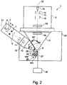
- Both the first particle beam column 2 and the second particle beam column 3 are arranged on a sample chamber 20 of the particle beam device 1.
- the first particle beam column 2 has a first beam axis 21.
- the second particle beam column 3 has a second beam axis 22.
- the second beam axis 22 corresponds to the vertical.
- the first particle beam column 2 and the second particle beam column 3 are arranged on the sample chamber 20 in such a way that the first beam axis 21 and the second beam axis 22 form a first angle W1, which is different from 0° and 180°.
- the first angle W1 is in the range of 15° to 80°, or in the range of 30° to 70°, or alternatively in the range of 45° to 60°.
- One embodiment provides for the first angle W1 to be approximately 54°.
- the first beam axis 21 and the second beam axis 22 intersect at a coincidence point 23, which will be discussed in even greater detail further below.
- a sample carrier 24 is arranged in the sample chamber 20 of the particle beam device 1, said sample carrier being embodied symmetrically with respect to a rotation axis 25.
- the sample carrier 24 is embodied such that it is rotatable about the rotation axis 25.
- a control device 26 is provided for controlling the rotation of the sample carrier 24 about the rotation axis 25, said control device being connected to the sample carrier 24.
- the sample carrier 24 has a movement device 27, by which the sample carrier 24 can be moved along the rotation axis 25.
- the movement device 27 therefore provides a translational movement of the sample carrier 24 along the rotation axis 25.
- the sample carrier 24 can be moved using the movement device 27 in three directions (for example arranged perpendicular to one another) (for example along an x-axis, a y-axis and a z-axis). Each of these three directions extends along a respective translational axis along which the sample carrier 24 is movable.
- the rotation axis 25 of the sample carrier 24 is oriented in such a way that it forms a second angle W2 with the first beam axis 21.
- the second angle W2 is different from 0° and 180°.
- the second angle W2 is in the range of 45° to 160°, or in the range of 90° to 120° or else in the range of 100° to 110°.
- the second angle W2 is approximately 108°.
- the rotation axis 25 forms an angle with the second beam axis 22 as well, namely the third angle W3.
- the third angle W3 is once again different from 0° and 180°.
- the third angle W3 is in the range of 1° to 80°, or in the range of 10° to 60° or alternatively in the range of 15° to 30°. In the exemplary embodiment illustrated here, the third angle W3 is approximately 18°.
- a sample holder 29 is arranged on a sample carrier surface 28 of the sample carrier 24 (also cf. Figure 3 ).
- the sample holder 29 and the sample carrier 24 are embodied as separate units.
- the sample holder 29 is connected to the sample carrier 24 using a fixing device in the form of a screw connection.
- An alternative embodiment provides for the sample holder 29 to be integrally formed on the sample carrier 24.
- the sample holder 29 can be arranged and fixed at different distances X from the rotation axis 25 in the radial direction. As the distance X increases, both in the first position of the sample carrier 24 the distance between a sample surface 32 and the first objective lens 10 of the first particle beam column 2 decreases and in the second position of the sample carrier 24 the distance WD between the sample surface 32 and the second objective lens 17 of the second particle beam column 3 decreases (working distance WD).
- the working distance WD can thus be set in order to enable the imaging properties (for example resolution) or working at low high voltages.
- the sample holder 29 is provided with a receiving surface 30, which is arranged in inclined fashion with respect to the sample carrier surface 28.
- the receiving surface 30 has a second surface normal 31, which forms a fourth angle W4 with the rotation axis 25.
- the fourth angle W4 is approximately 18°.
- the sample 8 is arranged on the receiving surface 30 in such a way that the sample surface 32 is arranged parallel to the receiving surface 30.
- the first surface normal of the sample surface 32 corresponds to the second surface normal 31.
- the invention is not restricted to this embodiment. Rather, embodiments in which the sample surface 32 is not arranged parallel to the receiving surface 30 are also provided. However, these embodiments also provide for the sample surface 32 to be able to be oriented parallel or substantially parallel to the beam axis 21.
- the sample holder 29 is embodied and arranged in an oriented fashion on the sample carrier 24 in such a way that the surface facing the second particle beam column 3 in the form of the receiving surface 30 of the sample holder 29, serving for receiving the sample 8, is oriented perpendicular to the second beam axis 22, that is to say that the surface normal to the surface facing the second particle beam column 3 is oriented parallel to the second beam axis 22.
- Figure 1 shows the sample carrier 24 in a first position. In this first position, the sample surface 32 of the sample 8 is oriented parallel to the first beam axis 21.
- Figure 2 shows the particle beam device 1 in accordance with Figure 1 . Therefore, identical structural parts are provided with the same reference symbols.
- Figure 2 in Figure 2 the sample carrier 24 is illustrated in a second position, in which the sample surface 32 of the sample 8 is oriented perpendicular to the second beam axis 22.
- Figure 3 shows a simplified schematic illustration of the first position of the sample carrier 24 (illustrated by dashed lines) and of the second position of the sample carrier 24 (solid lines).
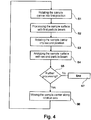
- FIG. 4 An exemplary flow chart of method steps is illustrated in Figure 4 .
- the sample carrier 24 is brought into the first position in accordance with Figure 1 . In one embodiment, this is effected exclusively by the rotation of the sample carrier 24 about the rotation axis 25. In a further embodiment, the position of the sample carrier 24 can be set as necessary using the control device 26 in such a way that the sample surface 32 is oriented parallel to the first beam axis 22.
- the sample surface 32 of the sample 8 is processed using the first particle beam (ion beam) (step S2).
- the first particle beam ion beam
- material is removed from the sample surface 32 or material is applied to the sample surface 32.
- the sample carrier 24 is brought from the first position into the second position (cf. Figures 2 and 3 ). This is effected exclusively by the rotation of the sample carrier 24 about the rotation axis 25 (step S3).
- the sample surface 32 of the sample 8 in the second position is always oriented perpendicular or approximately perpendicular to the second beam axis 22.
- the processed sample surface 32 is now analyzed using the second particle beam in the form of the electron beam (step S4).
- step S4 provides for the processed sample surface 32 to be imaged using the second particle beam.
- the first detector 18 and the second detector 19 detect interaction particles (for example secondary electrons and/or backscattered electrons), which arise when the electron beam impinges on the sample surface 32 as a result of the interaction of the electron beam with the sample surface 32.
- interaction particles for example secondary electrons and/or backscattered electrons
- step S5 a decision is made as to whether the sample 8 is to be processed and analyzed anew (step S5). If this is not the case, the method is ended in step S7. If this is the case, then, in a further step S6, the sample carrier 24 is moved using the movement device 27 along the rotation axis 25. Afterward, steps S1 to S5 are repeated.
- the invention is thus suitable for a series examination of the sample 8.
- a processing and an analysis of the sample 8 in series are possible in a simple and rapid manner since the change between the first position and the second position of the sample carrier 24 can be effected by a rotation of the sample carrier 24 about the rotation axis 25. Since the sample surface 32 in the second position is oriented perpendicular to the second beam axis 22, good imaging properties are obtained. Movements other than the rotation of the sample carrier 24 about the rotation axis 25 are not absolutely necessary.
- step S6 provides for moving the sample carrier 24 and thus the sample 8 along the rotation axis 25.
- This translational movement can be chosen for example depending on the processing of the sample surface 32.
- a further embodiment can provide for the first position also to be set by a movement of the sample carrier 24 along the translational axes in addition and/or as an alternative to the abovementioned translational movement along the rotation axis 25.
- the sample carrier 24 is moved along the rotation axis 25 and/or the translational axes in such a way that the sample surface 32, in the first position of the sample carrier 24, is at an identical first distance from the first end in the form of the first objective lens 10 of the first particle beam column 2 (first working distance).
- the sample carrier 24 is moved in such a way that, in the second position of the sample carrier 24, an identical second distance WD from the second end in the form of the second objective lens 17 of the second particle beam column 3 (second working distance WD) is always assumed. Consequently, it is not absolutely necessary to perform for example a refocusing of the second particle beam onto the sample surface 32 after each processing of the sample surface 32. However, in one embodiment of the invention, the fact that a slight refocusing is nevertheless carried out is indeed not excluded.
- the invention has the advantage that, using a single movement of the sample carrier 24, namely the rotation of the sample carrier 24 from the first position into the second position about the rotation axis 25, the sample surface 32 of the sample 8 can be oriented perpendicular to the second beam axis 22. Further movements are not absolutely necessary.
- the first working distance and/or the second working distance in comparison with the prior art, are/is less than the distance between the coincidence point 23 and the first particle beam column 2 and/or the second particle beam column 3.
- the invention provides for processing and/or analyzing the sample surface 32 of the sample 8 not at the coincidence point 23, but rather at points which are arranged significantly closer to the first particle beam column 2 and/or the second particle beam column 3 than the coincidence point 23. As a result of this, a better resolution capability than in the case of the prior art is obtained in particular in the second position during an imaging of the sample surface 32 using the second particle beam.
- the first working distance is in the range of 0.5 mm to 12 mm, wherein the range limits of this range are concomitantly encompassed thereby.
- approximately 1.0 mm can be chosen as the first working distance.
- the second working distance is in the range of 0.5 mm to 5 mm, wherein here too, the range limits of the aforementioned range are concomitantly encompassed thereby.
- approximately 1.5 mm can be chosen as the second working distance.
- the invention makes it possible that in the first position and/or in the second position of the sample carrier 24 imagings can be performed in which lower acceleration voltages than in comparison with the prior art can be used for particles of the first particle beam and/or particles of the second particle beam.
- acceleration voltages of less than 750 V are provided in the invention using particles of the second particle beam.
- an electron beam column (second particle beam column 3) is used for the analysis of the sample surface 32.
- an ion column in particular a device which is embodied as a gas field ion microscope, wherein the second particle beam is generated by gas atoms being ionized in the electrostatic field of an emission tip and the ions thus formed then being shaped into an ion beam that is then focused as an ion probe onto the sample surface 32.
- the first particle beam column 2, which serves for processing the sample surface 32 can also be embodied as a gas field ion column.
- the second particle beam column 3, which serves for analyzing the sample surface 32 should be operated with ions having a relatively low atomic mass, such as helium ions
- the first particle beam column 2, which serves for processing the sample surface 32 should be operated with ions having a relatively larger atomic mass, such as argon ions, neon ions or krypton ions.
Landscapes
- Chemical & Material Sciences (AREA)
- Analytical Chemistry (AREA)
- Physics & Mathematics (AREA)
- Engineering & Computer Science (AREA)
- Plasma & Fusion (AREA)
- Analysing Materials By The Use Of Radiation (AREA)
Applications Claiming Priority (1)
| Application Number | Priority Date | Filing Date | Title |
|---|---|---|---|
| DE102011002583.9A DE102011002583B9 (de) | 2011-01-12 | 2011-01-12 | Teilchenstrahlgerät und Verfahren zur Bearbeitung und/oder Analyse einer Probe |
Publications (3)
| Publication Number | Publication Date |
|---|---|
| EP2477206A2 true EP2477206A2 (de) | 2012-07-18 |
| EP2477206A3 EP2477206A3 (de) | 2015-04-22 |
| EP2477206B1 EP2477206B1 (de) | 2019-03-06 |
Family
ID=45495787
Family Applications (1)
| Application Number | Title | Priority Date | Filing Date |
|---|---|---|---|
| EP12150894.9A Active EP2477206B1 (de) | 2011-01-12 | 2012-01-12 | Verfahren zur Bearbeitung und/oder Analyse einer Probe mit einem Teilchenstrahlgerät |
Country Status (5)
| Country | Link |
|---|---|
| US (1) | US9455120B2 (de) |
| EP (1) | EP2477206B1 (de) |
| JP (1) | JP5964055B2 (de) |
| CN (1) | CN102592933B (de) |
| DE (1) | DE102011002583B9 (de) |
Families Citing this family (11)
| Publication number | Priority date | Publication date | Assignee | Title |
|---|---|---|---|---|
| US8686379B1 (en) * | 2010-09-07 | 2014-04-01 | Joseph C. Robinson | Method and apparatus for preparing serial planar cross sections |
| TWI628702B (zh) * | 2012-10-05 | 2018-07-01 | Fei公司 | 高「高寬比」結構之分析 |
| TWI686837B (zh) * | 2012-12-31 | 2020-03-01 | 美商Fei公司 | 用於具有一帶電粒子束之傾斜或偏斜研磨操作之基準設計 |
| US9734985B2 (en) | 2015-07-01 | 2017-08-15 | Kabushiki Kaisha Toshiba | Analytical apparatus, sample holder and analytical method |
| AU2018273352B2 (en) | 2017-05-22 | 2023-07-27 | Howmedica Osteonics Corp. | Device for in-situ fabrication process monitoring and feedback control of an electron beam additive manufacturing process |
| WO2018216108A1 (ja) * | 2017-05-23 | 2018-11-29 | 堺ディスプレイプロダクト株式会社 | 素子基板の製造方法およびレーザクリーニング装置 |
| US11117195B2 (en) | 2018-07-19 | 2021-09-14 | The University Of Liverpool | System and process for in-process electron beam profile and location analyses |
| DE102018212511B4 (de) * | 2018-07-26 | 2020-02-06 | Carl Zeiss Microscopy Gmbh | Aufnahmevorrichtung, Probenhalter-System und Verfahren zur Präparation mikroskopischer Proben |
| DE102018131609B3 (de) * | 2018-12-10 | 2020-02-06 | Carl Zeiss Microscopy Gmbh | Partikelstrahlsystem und Verfahren zum Betreiben eines Partikelstrahlsystems |
| CN109827980B (zh) * | 2019-03-19 | 2021-11-19 | 湖州灵粮生态农业有限公司 | 一种水果表面腐烂的自动化检测方法 |
| DE102021205001B4 (de) * | 2021-05-18 | 2023-07-27 | Carl Zeiss Microscopy Gmbh | Verfahren zum Positionieren von Objekten in einem Teilchenstrahlmikroskop mithilfe einer flexiblen Teilchenstrahlschranke sowie Computerprogrammprodukt |
Citations (3)
| Publication number | Priority date | Publication date | Assignee | Title |
|---|---|---|---|---|
| EP1443541B1 (de) | 2003-01-17 | 2008-12-10 | FEI Company | Verfahren zur Herstellung und Transmissionsbestrahlung einer Probe und geladene Teilchen-optisches System |
| DE102007026847A1 (de) | 2007-06-06 | 2008-12-11 | Carl Zeiss Nts Gmbh | Teilchenstrahlgerät und Verfahren zur Anwendung bei einem Teilchenstrahlgerät |
| DE102008041815A1 (de) | 2008-09-04 | 2010-04-15 | Carl Zeiss Nts Gmbh | Verfahren zur Analyse einer Probe |
Family Cites Families (13)
| Publication number | Priority date | Publication date | Assignee | Title |
|---|---|---|---|---|
| JP3117836B2 (ja) * | 1993-03-02 | 2000-12-18 | セイコーインスツルメンツ株式会社 | 集束イオンビーム装置 |
| EP1209737B2 (de) * | 2000-11-06 | 2014-04-30 | Hitachi, Ltd. | Verfahren zur Herstellung von Proben |
| KR20050040434A (ko) * | 2003-10-28 | 2005-05-03 | 삼성전자주식회사 | 집속 이온빔 장치의 시편 냉각 시스템 |
| DE10351276A1 (de) * | 2003-10-31 | 2005-06-16 | Leo Elektronenmikroskopie Gmbh | Teilchenstrahlgerät |
| JP4927345B2 (ja) * | 2005-04-07 | 2012-05-09 | ルネサスエレクトロニクス株式会社 | 試料体の加工観察装置及び試料体の観察方法 |
| EP1780764A1 (de) | 2005-11-01 | 2007-05-02 | FEI Company | Bühnenanordnung, teilchenoptische Vorrichtung mit einer derartigen Anordnung und Verfahren zur Behandlung einer Probe in einer derartigen Vorrichtung |
| JP2007164992A (ja) * | 2005-12-09 | 2007-06-28 | Sii Nanotechnology Inc | 複合荷電粒子ビーム装置 |
| JP5099291B2 (ja) * | 2006-02-14 | 2012-12-19 | エスアイアイ・ナノテクノロジー株式会社 | 集束イオンビーム装置及び試料の断面加工・観察方法 |
| JP2008204905A (ja) * | 2007-02-22 | 2008-09-04 | Hitachi High-Tech Science Systems Corp | イオンミリング装置、及びイオンミリング加工方法 |
| JP5055594B2 (ja) * | 2007-03-13 | 2012-10-24 | エスアイアイ・ナノテクノロジー株式会社 | 荷電粒子ビーム装置における試料移設方法及び荷電粒子ビーム装置 |
| US8835845B2 (en) | 2007-06-01 | 2014-09-16 | Fei Company | In-situ STEM sample preparation |
| JP5203781B2 (ja) * | 2008-04-08 | 2013-06-05 | 株式会社日立ハイテクノロジーズ | 試料ステージ装置及びその制御方法 |
| JP5250470B2 (ja) | 2009-04-22 | 2013-07-31 | 株式会社日立ハイテクノロジーズ | 試料ホールダ,該試料ホールダの使用法、及び荷電粒子装置 |
-
2011
- 2011-01-12 DE DE102011002583.9A patent/DE102011002583B9/de active Active
-
2012
- 2012-01-06 US US13/345,077 patent/US9455120B2/en active Active
- 2012-01-10 JP JP2012002595A patent/JP5964055B2/ja active Active
- 2012-01-10 CN CN201210005767.4A patent/CN102592933B/zh active Active
- 2012-01-12 EP EP12150894.9A patent/EP2477206B1/de active Active
Patent Citations (3)
| Publication number | Priority date | Publication date | Assignee | Title |
|---|---|---|---|---|
| EP1443541B1 (de) | 2003-01-17 | 2008-12-10 | FEI Company | Verfahren zur Herstellung und Transmissionsbestrahlung einer Probe und geladene Teilchen-optisches System |
| DE102007026847A1 (de) | 2007-06-06 | 2008-12-11 | Carl Zeiss Nts Gmbh | Teilchenstrahlgerät und Verfahren zur Anwendung bei einem Teilchenstrahlgerät |
| DE102008041815A1 (de) | 2008-09-04 | 2010-04-15 | Carl Zeiss Nts Gmbh | Verfahren zur Analyse einer Probe |
Also Published As
| Publication number | Publication date |
|---|---|
| EP2477206A3 (de) | 2015-04-22 |
| DE102011002583B9 (de) | 2018-06-28 |
| DE102011002583B4 (de) | 2017-09-28 |
| EP2477206B1 (de) | 2019-03-06 |
| CN102592933B (zh) | 2017-10-31 |
| JP5964055B2 (ja) | 2016-08-03 |
| JP2012146659A (ja) | 2012-08-02 |
| US20120205538A1 (en) | 2012-08-16 |
| CN102592933A (zh) | 2012-07-18 |
| DE102011002583A1 (de) | 2012-07-12 |
| US9455120B2 (en) | 2016-09-27 |
Similar Documents
| Publication | Publication Date | Title |
|---|---|---|
| EP2477206B1 (de) | Verfahren zur Bearbeitung und/oder Analyse einer Probe mit einem Teilchenstrahlgerät | |
| US8912491B2 (en) | Method of performing tomographic imaging of a sample in a charged-particle microscope | |
| TWI382442B (zh) | 電子束裝置 | |
| JP6177915B2 (ja) | 走査電子顕微鏡 | |
| US10699869B2 (en) | Operating a particle beam apparatus | |
| KR102373865B1 (ko) | 하전 입자 빔 시료 검사 시스템 및 그 동작 방법 | |
| EP2365514A1 (de) | Doppelstrahlige Ladungsträgerstrahlsäule und Betriebsverfahren dafür | |
| EP2708874A1 (de) | Verfahren zur Durchführung von Tomographiebildgebung einer Probe in einem Mikroskop mit geladenen Teilchen | |
| JP6010707B2 (ja) | 低速電子線回折検出モジュール及び走査型電子顕微鏡 | |
| KR102772061B1 (ko) | 하전 입자 빔 장치, 시료 가공 관찰 방법 | |
| US10103002B1 (en) | Method for generating an image of an object and particle beam device for carrying out the method | |
| CN110718433B (zh) | 带电粒子束布置、其操作方法及扫描电子装置 | |
| US10658152B1 (en) | Method for controlling a particle beam device and particle beam device for carrying out the method | |
| JP2020095959A (ja) | 粒子ビームシステム及び粒子ビームシステムの動作方法 | |
| CN113496860A (zh) | 粒子射束装置和复合射束装置 | |
| EP3236486A1 (de) | Verfahren zur erzeugung eines zusammengesetzen bildes eines objekts und teilchenstrahlvorrichtung zur durchführung des verfahrens | |
| US9595417B2 (en) | High resolution charged particle beam device and method of operating the same | |
| EP2355125A2 (de) | Teilchenstrahlgerät und Verfahren zum Betreiben eines Teilchenstrahlgeräts | |
| EP2840588B1 (de) | Verfahren zum Bearbeiten und/oder zum Beobachten eines Objekts sowie Teilchenstrahlgerät zur Durchführung des Verfahrens | |
| EP1916695A1 (de) | Ladungsträgerstrahlgerät und Verfahren zum Betrieb desselben | |
| US20240038481A1 (en) | Imaging, processing, and/or analyzing an object using a particle beam device | |
| CN118073159A (zh) | 粒子辐射设备操作方法、计算机程序产品、粒子辐射设备 | |
| US20250157782A1 (en) | Method for operating a particle beam apparatus, computer program product and particle beam apparatus for carrying out the method | |
| KR20250086502A (ko) | 경입자 빔 및 중입자 빔을 사용하는 입자 유도 x-선 방출 | |
| JP2014032943A (ja) | エネルギー幅の小さい電子ビームを試料に照射する走査型電子顕微鏡。 |
Legal Events
| Date | Code | Title | Description |
|---|---|---|---|
| PUAI | Public reference made under article 153(3) epc to a published international application that has entered the european phase |
Free format text: ORIGINAL CODE: 0009012 |
|
| AK | Designated contracting states |
Kind code of ref document: A2 Designated state(s): AL AT BE BG CH CY CZ DE DK EE ES FI FR GB GR HR HU IE IS IT LI LT LU LV MC MK MT NL NO PL PT RO RS SE SI SK SM TR |
|
| AX | Request for extension of the european patent |
Extension state: BA ME |
|
| PUAL | Search report despatched |
Free format text: ORIGINAL CODE: 0009013 |
|
| AK | Designated contracting states |
Kind code of ref document: A3 Designated state(s): AL AT BE BG CH CY CZ DE DK EE ES FI FR GB GR HR HU IE IS IT LI LT LU LV MC MK MT NL NO PL PT RO RS SE SI SK SM TR |
|
| AX | Request for extension of the european patent |
Extension state: BA ME |
|
| RIC1 | Information provided on ipc code assigned before grant |
Ipc: H01J 37/305 20060101ALI20150319BHEP Ipc: H01J 37/20 20060101AFI20150319BHEP Ipc: H01J 37/28 20060101ALI20150319BHEP |
|
| 17P | Request for examination filed |
Effective date: 20151013 |
|
| RBV | Designated contracting states (corrected) |
Designated state(s): AL AT BE BG CH CY CZ DE DK EE ES FI FR GB GR HR HU IE IS IT LI LT LU LV MC MK MT NL NO PL PT RO RS SE SI SK SM TR |
|
| STAA | Information on the status of an ep patent application or granted ep patent |
Free format text: STATUS: EXAMINATION IS IN PROGRESS |
|
| 17Q | First examination report despatched |
Effective date: 20171206 |
|
| GRAP | Despatch of communication of intention to grant a patent |
Free format text: ORIGINAL CODE: EPIDOSNIGR1 |
|
| STAA | Information on the status of an ep patent application or granted ep patent |
Free format text: STATUS: GRANT OF PATENT IS INTENDED |
|
| INTG | Intention to grant announced |
Effective date: 20180817 |
|
| GRAS | Grant fee paid |
Free format text: ORIGINAL CODE: EPIDOSNIGR3 |
|
| RAP1 | Party data changed (applicant data changed or rights of an application transferred) |
Owner name: CARL ZEISS MICROSCOPY GMBH |
|
| GRAA | (expected) grant |
Free format text: ORIGINAL CODE: 0009210 |
|
| STAA | Information on the status of an ep patent application or granted ep patent |
Free format text: STATUS: THE PATENT HAS BEEN GRANTED |
|
| AK | Designated contracting states |
Kind code of ref document: B1 Designated state(s): AL AT BE BG CH CY CZ DE DK EE ES FI FR GB GR HR HU IE IS IT LI LT LU LV MC MK MT NL NO PL PT RO RS SE SI SK SM TR |
|
| REG | Reference to a national code |
Ref country code: GB Ref legal event code: FG4D |
|
| REG | Reference to a national code |
Ref country code: CH Ref legal event code: EP Ref country code: AT Ref legal event code: REF Ref document number: 1105677 Country of ref document: AT Kind code of ref document: T Effective date: 20190315 |
|
| REG | Reference to a national code |
Ref country code: DE Ref legal event code: R096 Ref document number: 602012057351 Country of ref document: DE |
|
| REG | Reference to a national code |
Ref country code: IE Ref legal event code: FG4D |
|
| REG | Reference to a national code |
Ref country code: NL Ref legal event code: FP |
|
| REG | Reference to a national code |
Ref country code: LT Ref legal event code: MG4D |
|
| PG25 | Lapsed in a contracting state [announced via postgrant information from national office to epo] |
Ref country code: SE Free format text: LAPSE BECAUSE OF FAILURE TO SUBMIT A TRANSLATION OF THE DESCRIPTION OR TO PAY THE FEE WITHIN THE PRESCRIBED TIME-LIMIT Effective date: 20190306 Ref country code: LT Free format text: LAPSE BECAUSE OF FAILURE TO SUBMIT A TRANSLATION OF THE DESCRIPTION OR TO PAY THE FEE WITHIN THE PRESCRIBED TIME-LIMIT Effective date: 20190306 Ref country code: FI Free format text: LAPSE BECAUSE OF FAILURE TO SUBMIT A TRANSLATION OF THE DESCRIPTION OR TO PAY THE FEE WITHIN THE PRESCRIBED TIME-LIMIT Effective date: 20190306 Ref country code: NO Free format text: LAPSE BECAUSE OF FAILURE TO SUBMIT A TRANSLATION OF THE DESCRIPTION OR TO PAY THE FEE WITHIN THE PRESCRIBED TIME-LIMIT Effective date: 20190606 |
|
| PG25 | Lapsed in a contracting state [announced via postgrant information from national office to epo] |
Ref country code: LV Free format text: LAPSE BECAUSE OF FAILURE TO SUBMIT A TRANSLATION OF THE DESCRIPTION OR TO PAY THE FEE WITHIN THE PRESCRIBED TIME-LIMIT Effective date: 20190306 Ref country code: GR Free format text: LAPSE BECAUSE OF FAILURE TO SUBMIT A TRANSLATION OF THE DESCRIPTION OR TO PAY THE FEE WITHIN THE PRESCRIBED TIME-LIMIT Effective date: 20190607 Ref country code: HR Free format text: LAPSE BECAUSE OF FAILURE TO SUBMIT A TRANSLATION OF THE DESCRIPTION OR TO PAY THE FEE WITHIN THE PRESCRIBED TIME-LIMIT Effective date: 20190306 Ref country code: RS Free format text: LAPSE BECAUSE OF FAILURE TO SUBMIT A TRANSLATION OF THE DESCRIPTION OR TO PAY THE FEE WITHIN THE PRESCRIBED TIME-LIMIT Effective date: 20190306 Ref country code: BG Free format text: LAPSE BECAUSE OF FAILURE TO SUBMIT A TRANSLATION OF THE DESCRIPTION OR TO PAY THE FEE WITHIN THE PRESCRIBED TIME-LIMIT Effective date: 20190606 |
|
| REG | Reference to a national code |
Ref country code: AT Ref legal event code: MK05 Ref document number: 1105677 Country of ref document: AT Kind code of ref document: T Effective date: 20190306 |
|
| PG25 | Lapsed in a contracting state [announced via postgrant information from national office to epo] |
Ref country code: PT Free format text: LAPSE BECAUSE OF FAILURE TO SUBMIT A TRANSLATION OF THE DESCRIPTION OR TO PAY THE FEE WITHIN THE PRESCRIBED TIME-LIMIT Effective date: 20190706 Ref country code: AL Free format text: LAPSE BECAUSE OF FAILURE TO SUBMIT A TRANSLATION OF THE DESCRIPTION OR TO PAY THE FEE WITHIN THE PRESCRIBED TIME-LIMIT Effective date: 20190306 Ref country code: RO Free format text: LAPSE BECAUSE OF FAILURE TO SUBMIT A TRANSLATION OF THE DESCRIPTION OR TO PAY THE FEE WITHIN THE PRESCRIBED TIME-LIMIT Effective date: 20190306 Ref country code: ES Free format text: LAPSE BECAUSE OF FAILURE TO SUBMIT A TRANSLATION OF THE DESCRIPTION OR TO PAY THE FEE WITHIN THE PRESCRIBED TIME-LIMIT Effective date: 20190306 Ref country code: SK Free format text: LAPSE BECAUSE OF FAILURE TO SUBMIT A TRANSLATION OF THE DESCRIPTION OR TO PAY THE FEE WITHIN THE PRESCRIBED TIME-LIMIT Effective date: 20190306 Ref country code: EE Free format text: LAPSE BECAUSE OF FAILURE TO SUBMIT A TRANSLATION OF THE DESCRIPTION OR TO PAY THE FEE WITHIN THE PRESCRIBED TIME-LIMIT Effective date: 20190306 Ref country code: IT Free format text: LAPSE BECAUSE OF FAILURE TO SUBMIT A TRANSLATION OF THE DESCRIPTION OR TO PAY THE FEE WITHIN THE PRESCRIBED TIME-LIMIT Effective date: 20190306 |
|
| PG25 | Lapsed in a contracting state [announced via postgrant information from national office to epo] |
Ref country code: PL Free format text: LAPSE BECAUSE OF FAILURE TO SUBMIT A TRANSLATION OF THE DESCRIPTION OR TO PAY THE FEE WITHIN THE PRESCRIBED TIME-LIMIT Effective date: 20190306 Ref country code: SM Free format text: LAPSE BECAUSE OF FAILURE TO SUBMIT A TRANSLATION OF THE DESCRIPTION OR TO PAY THE FEE WITHIN THE PRESCRIBED TIME-LIMIT Effective date: 20190306 |
|
| REG | Reference to a national code |
Ref country code: DE Ref legal event code: R097 Ref document number: 602012057351 Country of ref document: DE |
|
| PG25 | Lapsed in a contracting state [announced via postgrant information from national office to epo] |
Ref country code: IS Free format text: LAPSE BECAUSE OF FAILURE TO SUBMIT A TRANSLATION OF THE DESCRIPTION OR TO PAY THE FEE WITHIN THE PRESCRIBED TIME-LIMIT Effective date: 20190706 Ref country code: AT Free format text: LAPSE BECAUSE OF FAILURE TO SUBMIT A TRANSLATION OF THE DESCRIPTION OR TO PAY THE FEE WITHIN THE PRESCRIBED TIME-LIMIT Effective date: 20190306 |
|
| PLBE | No opposition filed within time limit |
Free format text: ORIGINAL CODE: 0009261 |
|
| STAA | Information on the status of an ep patent application or granted ep patent |
Free format text: STATUS: NO OPPOSITION FILED WITHIN TIME LIMIT |
|
| PG25 | Lapsed in a contracting state [announced via postgrant information from national office to epo] |
Ref country code: DK Free format text: LAPSE BECAUSE OF FAILURE TO SUBMIT A TRANSLATION OF THE DESCRIPTION OR TO PAY THE FEE WITHIN THE PRESCRIBED TIME-LIMIT Effective date: 20190306 |
|
| 26N | No opposition filed |
Effective date: 20191209 |
|
| PG25 | Lapsed in a contracting state [announced via postgrant information from national office to epo] |
Ref country code: SI Free format text: LAPSE BECAUSE OF FAILURE TO SUBMIT A TRANSLATION OF THE DESCRIPTION OR TO PAY THE FEE WITHIN THE PRESCRIBED TIME-LIMIT Effective date: 20190306 |
|
| PG25 | Lapsed in a contracting state [announced via postgrant information from national office to epo] |
Ref country code: TR Free format text: LAPSE BECAUSE OF FAILURE TO SUBMIT A TRANSLATION OF THE DESCRIPTION OR TO PAY THE FEE WITHIN THE PRESCRIBED TIME-LIMIT Effective date: 20190306 |
|
| PG25 | Lapsed in a contracting state [announced via postgrant information from national office to epo] |
Ref country code: MC Free format text: LAPSE BECAUSE OF FAILURE TO SUBMIT A TRANSLATION OF THE DESCRIPTION OR TO PAY THE FEE WITHIN THE PRESCRIBED TIME-LIMIT Effective date: 20190306 |
|
| REG | Reference to a national code |
Ref country code: CH Ref legal event code: PL |
|
| GBPC | Gb: european patent ceased through non-payment of renewal fee |
Effective date: 20200112 |
|
| REG | Reference to a national code |
Ref country code: BE Ref legal event code: MM Effective date: 20200131 |
|
| PG25 | Lapsed in a contracting state [announced via postgrant information from national office to epo] |
Ref country code: FR Free format text: LAPSE BECAUSE OF NON-PAYMENT OF DUE FEES Effective date: 20200131 Ref country code: LU Free format text: LAPSE BECAUSE OF NON-PAYMENT OF DUE FEES Effective date: 20200112 Ref country code: GB Free format text: LAPSE BECAUSE OF NON-PAYMENT OF DUE FEES Effective date: 20200112 |
|
| PG25 | Lapsed in a contracting state [announced via postgrant information from national office to epo] |
Ref country code: CH Free format text: LAPSE BECAUSE OF NON-PAYMENT OF DUE FEES Effective date: 20200131 Ref country code: LI Free format text: LAPSE BECAUSE OF NON-PAYMENT OF DUE FEES Effective date: 20200131 Ref country code: BE Free format text: LAPSE BECAUSE OF NON-PAYMENT OF DUE FEES Effective date: 20200131 |
|
| PG25 | Lapsed in a contracting state [announced via postgrant information from national office to epo] |
Ref country code: IE Free format text: LAPSE BECAUSE OF NON-PAYMENT OF DUE FEES Effective date: 20200112 |
|
| PG25 | Lapsed in a contracting state [announced via postgrant information from national office to epo] |
Ref country code: MT Free format text: LAPSE BECAUSE OF FAILURE TO SUBMIT A TRANSLATION OF THE DESCRIPTION OR TO PAY THE FEE WITHIN THE PRESCRIBED TIME-LIMIT Effective date: 20190306 Ref country code: CY Free format text: LAPSE BECAUSE OF FAILURE TO SUBMIT A TRANSLATION OF THE DESCRIPTION OR TO PAY THE FEE WITHIN THE PRESCRIBED TIME-LIMIT Effective date: 20190306 |
|
| PGFP | Annual fee paid to national office [announced via postgrant information from national office to epo] |
Ref country code: NL Payment date: 20220119 Year of fee payment: 11 |
|
| PG25 | Lapsed in a contracting state [announced via postgrant information from national office to epo] |
Ref country code: MK Free format text: LAPSE BECAUSE OF FAILURE TO SUBMIT A TRANSLATION OF THE DESCRIPTION OR TO PAY THE FEE WITHIN THE PRESCRIBED TIME-LIMIT Effective date: 20190306 |
|
| REG | Reference to a national code |
Ref country code: NL Ref legal event code: MM Effective date: 20230201 |
|
| PG25 | Lapsed in a contracting state [announced via postgrant information from national office to epo] |
Ref country code: NL Free format text: LAPSE BECAUSE OF NON-PAYMENT OF DUE FEES Effective date: 20230201 |
|
| PGFP | Annual fee paid to national office [announced via postgrant information from national office to epo] |
Ref country code: DE Payment date: 20260121 Year of fee payment: 15 |
|
| PGFP | Annual fee paid to national office [announced via postgrant information from national office to epo] |
Ref country code: CZ Payment date: 20260106 Year of fee payment: 15 |