EP2476910B1 - Verfahren zur Überspannungsverhinderung in einem dynamischen Kompressor unter Verwendung eines adaptiven Vermeidersteuerungssystem und einer adaptiven Sicherheitsspanne - Google Patents
Verfahren zur Überspannungsverhinderung in einem dynamischen Kompressor unter Verwendung eines adaptiven Vermeidersteuerungssystem und einer adaptiven Sicherheitsspanne Download PDFInfo
- Publication number
- EP2476910B1 EP2476910B1 EP12151162.0A EP12151162A EP2476910B1 EP 2476910 B1 EP2476910 B1 EP 2476910B1 EP 12151162 A EP12151162 A EP 12151162A EP 2476910 B1 EP2476910 B1 EP 2476910B1
- Authority
- EP
- European Patent Office
- Prior art keywords
- compressor
- response
- surge
- model
- process disturbance
- Prior art date
- Legal status (The legal status is an assumption and is not a legal conclusion. Google has not performed a legal analysis and makes no representation as to the accuracy of the status listed.)
- Active
Links
Images


Classifications
-
- F—MECHANICAL ENGINEERING; LIGHTING; HEATING; WEAPONS; BLASTING
- F04—POSITIVE - DISPLACEMENT MACHINES FOR LIQUIDS; PUMPS FOR LIQUIDS OR ELASTIC FLUIDS
- F04D—NON-POSITIVE-DISPLACEMENT PUMPS
- F04D27/00—Control, e.g. regulation, of pumps, pumping installations or pumping systems specially adapted for elastic fluids
- F04D27/001—Testing thereof; Determination or simulation of flow characteristics; Stall or surge detection, e.g. condition monitoring
-
- F—MECHANICAL ENGINEERING; LIGHTING; HEATING; WEAPONS; BLASTING
- F04—POSITIVE - DISPLACEMENT MACHINES FOR LIQUIDS; PUMPS FOR LIQUIDS OR ELASTIC FLUIDS
- F04D—NON-POSITIVE-DISPLACEMENT PUMPS
- F04D27/00—Control, e.g. regulation, of pumps, pumping installations or pumping systems specially adapted for elastic fluids
- F04D27/02—Surge control
- F04D27/0207—Surge control by bleeding, bypassing or recycling fluids
- F04D27/0223—Control schemes therefor
Definitions
- the present invention is directed toward dynamic compressors. More specifically, the present invention is directed toward a method utilized by a control system within a dynamic compressor in order to provide surge protection for the dynamic compressor.
- a typical dynamic compressor has a gas inlet and a gas outlet wherein the compressor is driven by a compressor driver so that the gas, while flowing through the compressor, is compressed.
- a problem associated with dynamic compressors is the amount of gas flow that is provided at the gas inlet. Specifically, if an insufficient amount of gas flow is provided, a surge within the system occurs causing damage to the compressor. Because of the high price of compressors great care must be taken to ensure that compressors are not damaged.
- a recycle or surge control valve is installed around dynamic compressors where the surge control valve opens to divert gas flow from the outlet of the compressor and recycle it to the inlet of the compressor to ensure that there is always sufficient gas flow in the inlet to prevent surges from occurring.
- Compressor surge control systems also known as anti-surge controllers
- a standard PID controller for regulating the surge control valve when flow rate decreases below a predefined set point.
- the set point for recycling is established based on heuristic rules and operating guidelines typically set as a fixed margin from a surge limit line (or minimum flow set point).
- control systems in the prior art employ the use of a fixed and variable set point to adjust the safety margin based on compressor flow rate changes.
- the problem with these control systems is that the rate of approach to surge is determined based on the derivative of a flow signal that is typically very noisy in field installations.
- the control system dampens out the noisy signal through the use of passive digital filters rendering the variable set point determination ineffective and impractical in the field.
- these control systems are very difficult to tune in the field because these techniques are not self adapting to varying process conditions.
- Control systems based on closed loop rate limiting of the surge variable such as USPN 5,798,941 suffer from the aspect of using a noisy derivative of flow signal as a process variable to determine quick valve opening.
- another problem is that establishing the rate set point for optimum control response is very difficult for a field engineer.
- tuning a prior art control system in the field also is extremely challenging because the known prior art techniques are not self adapting to changes in field conditions and instead require high level of expertise in the field.
- US 2009/0274565 discloses a method of operating a compressor of a compressor system is disclosed.
- the method uses three models.
- Each model of the three models describes a surge line of the compressor as a function of any two of three operating parameters of the compressor.
- the three operating parameters include head H, flow Q, and speed N.
- the method includes measuring operating characteristics of the compressor system using sensors, and determining a current value of the three operating parameters based on at least some of the measured operating characteristics.
- the method also includes locating operating points of the compressor on each of the three models based on the current value of the operating parameters, and identifying a sensor fault that affects the determination of at least one of the operating parameters.
- the method further includes avoiding surge of the compressor using one model of the three models.
- the one model being a model that is a function of two operating parameters unaffected by the sensor fault.
- WO 02/38963 A1 discloses a method and a device for actively controlling surge in a rotational compressor, the compressor being driven by an electric drive and controlled by an active surge control system.
- the active surge control system comprises an active surge controller which measures and/or observes at least one system state (M>1 ⁇ ... M>n ⁇ , V>s ⁇ ) of the compressor, and calculates a commanded output of the electric drive for maintaining a stable operation of the compressor. Further, the compressor sends a signal (U>s ⁇ ) comprising the commanded output to the electric drive and adjusts the output of the drive in accordance with the commanded output.
- EP 2042743 A1 discloses a gas compression system comprising a compressor for compressing a gas fed to the compressor, an electric motor driving the compressor, a compressor motor drive unit producing current to said motor, a pipe for feeding back gas from the outlet of the compressor to the inlet of the compressor, a recycle valve controlling the gas flow in the pipe, an actuator for actuating the recycle valve, and a control unit generating a control signal to said actuator for controlling the opening and closing of the recycle valve.
- the actuator comprises an electric motor controlling the opening and closing of the recycle valve.
- the gas compression system further comprises measuring equipment for measuring the input voltage to the compressor motor drive unit, and the control unit is adapted to determine whether there is a risk of surge of the compressor based on the measured input voltage to the compressor motor drive unit, and to generate a control signal for opening the recycle valve if it is determined that there is a risk of surge of the compressor.
- a principal object of the present invention is to provide a control system and method for providing improved protection for a dynamic compressor.
- Yet another object of the present invention is to provide an adaptive safety margin determination based on process disturbance modeling using a compressor load variable.
- Another object of the present invention is to provide an adaptive surge preventer control system for a turbo compressor.
- a method of preventing surge in a dynamic compressor comprising the steps of: providing a surge valve having an adjustable opening for increasing the flow through a dynamic compressor; sensing process conditions in the dynamic compressor to determine a compressor load variable; estimating a process disturbance model using the compressor load variable; and initiating a closed loop control response to open the surge valve based on the process disturbance model, wherein the closed loop control response is initiated by opening the surge valve at a rate as a function of a compressor dynamic operating point distance from a surge limit line and wherein the surge valve is opened in a step response or a ramp response.
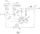
- Fig. 1 shows a dynamic compressor 10 that includes a compressor 12 that is driven by a compressor driver 14.
- the compressor driver is of any type including a motor, gas turbine, steam turbine or the like.
- the compressor 12 has a gas inlet 16 and a gas outlet 18 wherein gas flows through the compressor 12 to be compressed.
- a surge or recycle valve 20 is fluidly connected between the gas inlet 16 and gas outlet 18 so that when the surge valve 20 opens a fluid flow path exists to convey gas from the gas outlet 18 to the gas inlet 16.
- a plurality of sensors 22 including pressure sensors, temperature sensors, flow measurement sensors and the like are placed throughout the dynamic compressor 10 in order to determine processed conditions for the components of the dynamic compressor including the compressor 12, the driver 14, the gas inlet 16, and gas outlet 18 and the surge valve 20.
- the plurality of sensors 22 are electrically connected to the control system 24 where the control system is in real time communication with all of the components of the dynamic compressor and controls the opening of the surge valve 20.
- Control system 24 utilizes the plurality of sensors 22 to determine process conditions so that a compressor load variable can be calculated.
- the compressor load variable can be determined based on different methods.
- the compressor load variable can be determined by using the compressor dynamic operating point as a function of surge limit.
- the compressor load variable also can be determined by calculating the power of the compressor driver 14 or the rotating speed of the compressor driver 14.
- the compressor load variable can also be determined by a system process variable such as header pressure or header flow of the compressor 12 connected in a compression network.
- a final way of determining the compressor load variable is through mathematical modeling of the compressor 12, the driver 14 or the associated process. Specifically, the compressor load variable is determined using any of these or a combination.
- the control system 24 after determining the compressor load variable, estimates a process disturbance model using one of several methods. The first is to take a digital derivative of the compressor load variable. The second is to take a delayed response of the compressor load variable. The third is to utilize filter response of the compressor load variable. The fourth is to utilize a surge model response of the compressor load variable. Once a process disturbance model is estimated a safety margin can be adjusted using a rate limited response of the process disturbance that is obtained and a closed loop response using process feedback can be initiated.
- Fig. 3 shows an adaptive set point calculation by the control system 24 utilized to determine an adaptive safety margin.
- the compressor load variable is inputted into a digital filtering disturbance model 30.
- the control system 24 then utilizes a rate of change detector 32 to provide a signal 34 of a safety margin that is then presented to a model based dynamic rate limiter 36 in order to differentiate steady state response from process disturbance upsets.
- Fig. 4 shows an example of a dynamic rate limiter 36 that uses a steady state model 38 in combination with a disturbance model 40 to provide adaptive set points 42 and 43 in order to arrive at an adaptive safety margin.
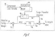
- Fig. 5 shows an adaptive closed loop surge preventer response process 44 that is based on the distance of compressor operating point from the surge-line and provides an adaptive closed loop fast response.
- a process disturbance dynamic model with provisions for differentiating steady state response from process disturbance upsets adjusts the closed loop response further in response to disturbance model output.
- the distance of compressor operating point to surge line is communicated to a system function 48 to send a response signal 50 that is considered an adaptive surge preventer response signal.
- the compressor load variable is inputted into a disturbance model 46 in order to estimate a process disturbance model.
- the process disturbance model is then communicated to a system function 48 to send a response signal 50, that is considered an adaptive surge preventer response signal in another embodiment.
- the surge controller 52 sends a signal 53 to be summed with the response signal 50 at summation point 54 before the signal goes to the surge valve 20.
- the control system 24 upon crossing of a predetermined second set point such as a surge preventer open surge preventer control line as shown in Fig. 2 the control system 24 initiates the closed loop adaptive surge preventer response based on a compressor load feed back variable.
- a predetermined second set point such as a surge preventer open surge preventer control line as shown in Fig. 2
- the control system 24 initiates the closed loop adaptive surge preventer response based on a compressor load feed back variable.
- the method is self adaptive because a compress feedback variable is used to determine the size of the response going forward in time.
- a dynamic compressor 10 that utilizes a control system 24 that provides a method of adjusting a recycle valve 20 that improves upon the state of the art. Specifically, by determining an adaptive safety margin based upon a compressor load variable to provide a process disturbance model, improved control of the surge valve 20 and protection of the dynamic compressor 10 is provided. Additionally, by using an online determination of parameters based on steady state and dynamic change of compressor load variable measurements an adaptive safety margin rate is utilized thus providing an improved functioning over the prior art. Further, by utilizing the process disturbance model, process feedback is used to determine the size of the response of the control system 24 going forward instead of relying on heuristic open loop jumps as a function of time or gain changes in proportion to control loop error. Therefore, an adaptive closed loop fast response comes from an online self compensation or self correction of the surge valve action as a result of the steady state and dynamic model of compressor load variable measurements improving upon the state of the art. Thus, at the very least all of the stated objectives have been met.
Landscapes
- Engineering & Computer Science (AREA)
- Mechanical Engineering (AREA)
- General Engineering & Computer Science (AREA)
- Life Sciences & Earth Sciences (AREA)
- Sustainable Development (AREA)
- Control Of Positive-Displacement Air Blowers (AREA)
Claims (13)
- Verfahren zum Verhindern von Druckstößen in einem dynamischen Kompressor (10), wobei das Verfahren die folgenden Schritte beinhaltet:Bereitstellen eines Druckstoßventils (20) mit einer einstellbaren Öffnung zum Erhöhen des Durchflusses durch einen dynamischen Kompressor (10);Erfassen von Prozessbedingungen in dem dynamischen Kompressor, um eine Kompressorlastvariable zu bestimmen;Schätzen eines Prozessstörungsmodells anhand der Kompressorlastvariablen; undEinleiten einer Regelkreis-Regelreaktion zum Öffnen des Druckstoßventils (20) auf der Basis des Prozessstörungsmodells, wobei die Regelkreis-Regelreaktion durch Öffnen des Druckstoßventils (20) mit einer Rate in Abhängigkeit von einem dynamischen Betriebspunktabstand des Kompressors von einer Druckstoßgrenzlinie eingeleitet wird und wobei das Druckstoßventil (20) in einer stufenförmigen Reaktion oder einer rampenförmigen Reaktion geöffnet wird.
- Verfahren nach Anspruch 1, das ferner die folgenden Schritte beinhaltet:Einstellen einer Sicherheitsmarge auf der Basis des Prozessstörungsmodells; undEinstellen der Öffnung des Druckstoßventils (20) gemäß der Sicherheitsmarge.
- Verfahren nach Anspruch 1 oder 2, bei dem die Kompressorlast variabel ist:a) bestimmt auf der Basis einer Kompressorantriebsleistung, wobei vorzugsweise der Kompressorantrieb (14) aus der Gruppe bestehend aus Motor, Dampfturbine und Gasturbine ausgewählt wird;b) bestimmt auf der Basis der Drehzahl des Kompressorantriebs;c) bestimmt auf der Basis einer Systemprozessvariablen, wobei vorzugsweise eine Systemprozessvariable ein Sammlerdruck oder Fluss eines mit dem Kompressor (10) assoziierten Prozesses ist; oderd) bestimmt auf der Basis einer mathematischen Modellierung einer Systemkomponente; odere) bestimmt auf der Basis eines dynamischen Betriebspunkts des Kompressors in Abhängigkeit von der Druckstoßgrenzlinie.
- Verfahren nach Anspruch 1 oder 2, wobei das Prozessstörungsmodell:a) anhand einer digitalen Ableitung der Kompressorlastvariablen geschätzt wird;b) anhand einer verzögerten Reaktion der Kompressorlastvariablen geschätzt wird;c) anhand einer Filterreaktion der Kompressorlastvariablen geschätzt wird, wobei das Filter vorzugsweise ein Vorlauf-Nachlauf-Filter ist; oderd) anhand einer Druckstoßmodellreaktion der Kompressorlast geschätzt wird.
- Verfahren nach Anspruch 4, wobei das Prozessstörungsmodell anhand einer Druckstoßmodellreaktion der Kompressorlast geschätzt wird und wobei die Druckstoßmodellreaktion der Kompressorlast bestimmt wird, wenn der dynamische Betriebspunkt des Kompressors (10) die Druckstoßgrenzlinie um eine konfigurierte Marge überschreitet.
- Verfahren nach Anspruch 4, wobei das Prozessstörungsmodell anhand einer Druckstoßmodellreaktion der Kompressorlast geschätzt wird und wobei die Druckstoßmodellreaktion der Kompressorlast bestimmt wird, wenn die Änderungsrate der Kompressorlastvariablen eine definierte Grenze überschreitet.
- Verfahren nach Anspruch 6, wobei die Kompressorlastvariable:a) ein Durchfluss des Kompressors (10) ist;b) ein mit dem Kompressor (10) assoziierter Temperaturmesswert ist;c) ein mit dem Kompressor (10) assoziierter Druckmesswert ist;d) ein Abstand des Betriebspunktes des Kompressors von einer Druckstoßgrenzlinie ist;d) die Leistung des Kompressorantriebs (14) ist; odere) die Geschwindigkeit des Kompressors (10) ist.
- Verfahren nach Anspruch 1 oder 2, das ferner den Schritt des Differenzierens zwischen einer stationären Reaktion und Prozessstörungen beinhaltet.
- Verfahren nach Anspruch 2, wobei die Sicherheitsmarge anhand einer ratenbegrenzten Reaktion auf der Basis des Prozessstörungsmodells eingestellt wird.
- Verfahren nach Anspruch 2, das ferner den folgenden Schritt beinhaltet:a) Erhöhen der Sicherheitsmarge auf der Basis einer Zunahme der Reaktion des Prozessstörungsmodells, wobei vorzugsweise die Zunahme der Reaktion des Prozessstörungsmodells einer negativen Annäherungsrate des dynamischen Betriebspunkts des Kompressors an eine Druckstoßgrenzlinie entspricht; oderb) Zurücksetzen der Sicherheitsmarge auf der Basis einer ratenbegrenzten Reaktion auf eine Abnahme der Prozessstörungsmodellreaktion, wobei vorzugsweise die Abnahme der Prozessstörungsmodellreaktion einer positiven Annäherungsrate des dynamischen Betriebspunkts des Kompressors an eine Druckstoßgrenzlinie entspricht.
- Verfahren nach Anspruch 2, wobei das Druckstoßventil immer dann geöffnet wird, wenn ein Abstand des dynamischen Betriebspunkts des Kompressors von der Druckstoßgrenzlinie kleiner als die Sicherheitsmarge ist.
- Verfahren nach Anspruch 1, wobei:a) die stufenförmige Öffnung fest ist oder mit der Reaktion des Prozessstörungsmodells variiert wird; oderb) die rampenförmige Reaktionsrate fest ist oder die rampenförmige Reaktionsrate mit der Reaktion des Prozessstörungsmodells variiert wird.
- Verfahren nach Anspruch 1, wobei:a) das Druckstoßventil (20) geöffnet wird, wenn der Betriebspunkt des Kompressors (10) in einem Abstand liegt, der kleiner als ein vorbestimmter Sollwert ist; oderb) das Druckstoßventil (20) anhand einer ratenbegrenzten Reaktion geschlossen wird, sobald ein vorbestimmter Sollwert überschritten wird, und wobei vorzugsweisei) die Schließrate des Druckstoßventils (20) auf der Basis der Prozeßstörungsmodellreaktion eingestellt wird;ii) die Schließrate des Druckstoßventils (20) auf der Basis eines Abstands des dynamischen Betriebspunktes des Kompressors von einer Druckstoßgrenzlinie eingestellt wird;iii) das Druckstoßventil (20) auf der Basis einer Regelkreis-Regelreaktion geschlossen wird.
Applications Claiming Priority (1)
| Application Number | Priority Date | Filing Date | Title |
|---|---|---|---|
| US13/005,601 US9133850B2 (en) | 2011-01-13 | 2011-01-13 | Method for preventing surge in a dynamic compressor using adaptive preventer control system and adaptive safety margin |
Publications (3)
| Publication Number | Publication Date |
|---|---|
| EP2476910A2 EP2476910A2 (de) | 2012-07-18 |
| EP2476910A3 EP2476910A3 (de) | 2018-01-17 |
| EP2476910B1 true EP2476910B1 (de) | 2020-12-23 |
Family
ID=45495800
Family Applications (1)
| Application Number | Title | Priority Date | Filing Date |
|---|---|---|---|
| EP12151162.0A Active EP2476910B1 (de) | 2011-01-13 | 2012-01-13 | Verfahren zur Überspannungsverhinderung in einem dynamischen Kompressor unter Verwendung eines adaptiven Vermeidersteuerungssystem und einer adaptiven Sicherheitsspanne |
Country Status (2)
| Country | Link |
|---|---|
| US (2) | US9133850B2 (de) |
| EP (1) | EP2476910B1 (de) |
Families Citing this family (18)
| Publication number | Priority date | Publication date | Assignee | Title |
|---|---|---|---|---|
| US10900492B2 (en) * | 2010-05-11 | 2021-01-26 | Energy Control Technologies, Inc. | Method of anti-surge protection for a dynamic compressor using a surge parameter |
| US9133850B2 (en) * | 2011-01-13 | 2015-09-15 | Energy Control Technologies, Inc. | Method for preventing surge in a dynamic compressor using adaptive preventer control system and adaptive safety margin |
| JP5634907B2 (ja) * | 2011-02-10 | 2014-12-03 | 株式会社日立製作所 | 圧縮機の制御装置及び制御方法 |
| US10436208B2 (en) * | 2011-06-27 | 2019-10-08 | Energy Control Technologies, Inc. | Surge estimator |
| ITCO20120056A1 (it) * | 2012-11-07 | 2014-05-08 | Nuovo Pignone Srl | Metodo per operare un compressore in caso di malfunzionamento di uno o piu' segnali di misura |
| US20150361902A1 (en) * | 2013-03-01 | 2015-12-17 | United Technologies Corporation | Gas turbine engine anti-surge valve discharge tube |
| FR3004759B1 (fr) * | 2013-04-23 | 2015-05-15 | Snecma | Procede et dispositif de generation d'une commande de debit de carburant destine a etre injecte dans une chambre de combustion d'une turbomachine |
| WO2015138172A1 (en) * | 2014-03-11 | 2015-09-17 | Borgwarner Inc. | Method for identifying the surge limit of a compressor |
| US9551276B2 (en) * | 2014-08-14 | 2017-01-24 | Ford Global Technologies, Llc | Methods and systems for surge control |
| CN104793656B (zh) * | 2015-04-07 | 2017-07-07 | 华北电力科学研究院有限责任公司 | 旁路压力设定值的确定方法及装置 |
| EP3147511A1 (de) * | 2015-09-22 | 2017-03-29 | Siemens Aktiengesellschaft | Verfahren zur pumpgrenzreglung, turboverdichter |
| RU2016112469A (ru) * | 2016-04-01 | 2017-10-04 | Фишер-Роузмаунт Системз, Инк. | Способы и устройство для обнаружения и предотвращения помпажа компрессора |
| IT201600070852A1 (it) * | 2016-07-07 | 2018-01-07 | Nuovo Pignone Tecnologie Srl | Protezione anti-pompaggio di compressore in condizioni di gas umido |
| US10316740B2 (en) * | 2017-02-15 | 2019-06-11 | Borgwarner Inc. | Systems including an electrically assisted turbocharger and methods of using the same |
| WO2020009825A1 (en) | 2018-07-02 | 2020-01-09 | Cummins Inc. | Compressor surge control |
| CN110657031B (zh) * | 2019-09-30 | 2020-10-23 | 山东超越数控电子股份有限公司 | 飞机发动机喘振识别方法 |
| CN113985808B (zh) * | 2021-09-17 | 2024-04-23 | 北京化工大学 | 基于最小阶跃扰动的负荷切换路径寻优方法 |
| IT202200001415A1 (it) * | 2022-01-28 | 2023-07-28 | Nuovo Pignone Srl | Compressore centrifugo con recupero di energia di riciclo |
Family Cites Families (19)
| Publication number | Priority date | Publication date | Assignee | Title |
|---|---|---|---|---|
| US3606754A (en) * | 1969-05-19 | 1971-09-21 | Chandler Evans Inc | Hybrid fuel control |
| US4142838A (en) | 1977-12-01 | 1979-03-06 | Compressor Controls Corporation | Method and apparatus for preventing surge in a dynamic compressor |
| US4697980A (en) * | 1984-08-20 | 1987-10-06 | The Babcock & Wilcox Company | Adaptive gain compressor surge control system |
| US4949276A (en) | 1988-10-26 | 1990-08-14 | Compressor Controls Corp. | Method and apparatus for preventing surge in a dynamic compressor |
| NO952860L (no) * | 1994-08-08 | 1996-02-09 | Compressor Controls Corp | Framgangsmåte og apparat for å hindre parameterdrift i gassturbiner |
| JPH096404A (ja) * | 1995-06-20 | 1997-01-10 | Toshiba Corp | ディジタルpid制御装置 |
| US5709526A (en) | 1996-01-02 | 1998-01-20 | Woodward Governor Company | Surge recurrence prevention control system for dynamic compressors |
| CA2231443C (en) | 1996-01-02 | 2002-03-26 | Woodward Governor Company | Surge prevention control system for dynamic compressors |
| US5951240A (en) * | 1997-11-21 | 1999-09-14 | Compressor Controls Corporation | Method and apparatus for improving antisurge control of turbocompressors by reducing control valve response time |
| US6142229A (en) * | 1998-09-16 | 2000-11-07 | Atlantic Richfield Company | Method and system for producing fluids from low permeability formations |
| US6494672B1 (en) * | 1999-06-07 | 2002-12-17 | Compressor Controls Corporation | Method and apparatus for antisurge control of turbocompressors having complex and changing surge limit lines |
| DE10001365A1 (de) * | 2000-01-14 | 2001-07-19 | Man Turbomasch Ag Ghh Borsig | Verfahren und Einrichtung zum Regeln eines Turbokompressors zur Verhinderung des Pumpens |
| NO313926B1 (no) * | 2000-11-08 | 2002-12-23 | Abb Research Ltd | Kompressorstyring |
| US7096669B2 (en) * | 2004-01-13 | 2006-08-29 | Compressor Controls Corp. | Method and apparatus for the prevention of critical process variable excursions in one or more turbomachines |
| EP1659294B1 (de) * | 2004-11-17 | 2017-01-11 | Mitsubishi Heavy Industries Compressor Corporation | Verdichtersteuereinheit und Gasturbinenkraftanlage mit dieser Einheit |
| EP2042743B1 (de) * | 2007-09-27 | 2014-11-05 | ABB Research Ltd. | Gaskompressionssystem und Verfahren zur Steuerung eines Gaskompressionssystems. |
| US8152496B2 (en) * | 2008-05-02 | 2012-04-10 | Solar Turbines Inc. | Continuing compressor operation through redundant algorithms |
| US8342794B2 (en) * | 2009-05-19 | 2013-01-01 | General Electric Company | Stall and surge detection system and method |
| US9133850B2 (en) * | 2011-01-13 | 2015-09-15 | Energy Control Technologies, Inc. | Method for preventing surge in a dynamic compressor using adaptive preventer control system and adaptive safety margin |
-
2011
- 2011-01-13 US US13/005,601 patent/US9133850B2/en active Active
-
2012
- 2012-01-13 EP EP12151162.0A patent/EP2476910B1/de active Active
-
2015
- 2015-07-21 US US14/804,430 patent/US10859087B2/en active Active
Non-Patent Citations (1)
| Title |
|---|
| None * |
Also Published As
| Publication number | Publication date |
|---|---|
| US20120183385A1 (en) | 2012-07-19 |
| US9133850B2 (en) | 2015-09-15 |
| US20150322956A1 (en) | 2015-11-12 |
| US10859087B2 (en) | 2020-12-08 |
| EP2476910A2 (de) | 2012-07-18 |
| EP2476910A3 (de) | 2018-01-17 |
Similar Documents
| Publication | Publication Date | Title |
|---|---|---|
| US9133850B2 (en) | Method for preventing surge in a dynamic compressor using adaptive preventer control system and adaptive safety margin | |
| US9360026B2 (en) | Positioner | |
| US20130048114A1 (en) | Controlled hydronic distribution system | |
| US10288037B2 (en) | Method for controlling a rotational speed threshold of a wind turbine, and a corresponding wind turbine | |
| WO2008105921A2 (en) | Anti-bogdown control system for turbine/compressor systems | |
| CN111123770B (zh) | 一种fcb工况下旁路模型开度确定方法及装置 | |
| JP2010229962A (ja) | 水車またはポンプ水車用調速制御装置 | |
| JP2010019223A (ja) | ポンプ流量制御方法およびポンプ流量制御システム | |
| CN108425876A (zh) | 一种适用于泵管路系统的蝶阀装置及其控制方法 | |
| CN101479678A (zh) | 用于在涡轮机上实施调节机构功能测试的设备和方法 | |
| CA2588879C (en) | Steam turbine plant | |
| WO2017071548A1 (zh) | 设备出力突变平衡控制方法及系统 | |
| CN107075974A (zh) | 具有热应力控制器作为主控制器的涡轮机控制单元 | |
| CN111399479A (zh) | 一种基于参数预测的高加系统故障监测方法及系统 | |
| JPH01285698A (ja) | 吹出しによりターボ圧縮機のサージを回避する調整方法 | |
| US11519340B2 (en) | System and method for controlling a speed of rotation of an aircraft turbine engine with fault management | |
| CN100396886C (zh) | 用于对借助于发电机与供电网连接的透平进行转速调节的方法及装置 | |
| JP2002147253A (ja) | ガスタービン保護装置及び燃料制御装置 | |
| WO2013110324A1 (en) | Dynamic compressor control with surge prevention | |
| JP6587350B2 (ja) | ガスタービン冷却系統、これを備えるガスタービン設備、ガスタービン冷却系統の制御方法 | |
| JP6114130B2 (ja) | タービン制御装置およびタービン制御方法 | |
| KR101945413B1 (ko) | 압축기 제어 시스템 및 압축기의 제어 방법 | |
| WO2002038963A1 (en) | Active compressor stability control | |
| CN103256624B (zh) | 一种火电厂炉膛负压的控制方法和控制系统 | |
| JP5948165B2 (ja) | 馬力制限装置及び馬力制限方法 |
Legal Events
| Date | Code | Title | Description |
|---|---|---|---|
| PUAI | Public reference made under article 153(3) epc to a published international application that has entered the european phase |
Free format text: ORIGINAL CODE: 0009012 |
|
| AK | Designated contracting states |
Kind code of ref document: A2 Designated state(s): AL AT BE BG CH CY CZ DE DK EE ES FI FR GB GR HR HU IE IS IT LI LT LU LV MC MK MT NL NO PL PT RO RS SE SI SK SM TR |
|
| AX | Request for extension of the european patent |
Extension state: BA ME |
|
| RAP1 | Party data changed (applicant data changed or rights of an application transferred) |
Owner name: ENERGY CONTROL TECHNOLOGIES, INC. |
|
| PUAL | Search report despatched |
Free format text: ORIGINAL CODE: 0009013 |
|
| AK | Designated contracting states |
Kind code of ref document: A3 Designated state(s): AL AT BE BG CH CY CZ DE DK EE ES FI FR GB GR HR HU IE IS IT LI LT LU LV MC MK MT NL NO PL PT RO RS SE SI SK SM TR |
|
| AX | Request for extension of the european patent |
Extension state: BA ME |
|
| RIC1 | Information provided on ipc code assigned before grant |
Ipc: F04D 27/02 20060101ALI20171211BHEP Ipc: F04D 27/00 20060101AFI20171211BHEP |
|
| STAA | Information on the status of an ep patent application or granted ep patent |
Free format text: STATUS: REQUEST FOR EXAMINATION WAS MADE |
|
| 17P | Request for examination filed |
Effective date: 20180717 |
|
| RBV | Designated contracting states (corrected) |
Designated state(s): AL AT BE BG CH CY CZ DE DK EE ES FI FR GB GR HR HU IE IS IT LI LT LU LV MC MK MT NL NO PL PT RO RS SE SI SK SM TR |
|
| STAA | Information on the status of an ep patent application or granted ep patent |
Free format text: STATUS: EXAMINATION IS IN PROGRESS |
|
| 17Q | First examination report despatched |
Effective date: 20191114 |
|
| GRAP | Despatch of communication of intention to grant a patent |
Free format text: ORIGINAL CODE: EPIDOSNIGR1 |
|
| STAA | Information on the status of an ep patent application or granted ep patent |
Free format text: STATUS: GRANT OF PATENT IS INTENDED |
|
| INTG | Intention to grant announced |
Effective date: 20200707 |
|
| GRAS | Grant fee paid |
Free format text: ORIGINAL CODE: EPIDOSNIGR3 |
|
| GRAA | (expected) grant |
Free format text: ORIGINAL CODE: 0009210 |
|
| STAA | Information on the status of an ep patent application or granted ep patent |
Free format text: STATUS: THE PATENT HAS BEEN GRANTED |
|
| AK | Designated contracting states |
Kind code of ref document: B1 Designated state(s): AL AT BE BG CH CY CZ DE DK EE ES FI FR GB GR HR HU IE IS IT LI LT LU LV MC MK MT NL NO PL PT RO RS SE SI SK SM TR |
|
| REG | Reference to a national code |
Ref country code: GB Ref legal event code: FG4D |
|
| REG | Reference to a national code |
Ref country code: DE Ref legal event code: R096 Ref document number: 602012073802 Country of ref document: DE |
|
| REG | Reference to a national code |
Ref country code: AT Ref legal event code: REF Ref document number: 1347990 Country of ref document: AT Kind code of ref document: T Effective date: 20210115 |
|
| REG | Reference to a national code |
Ref country code: IE Ref legal event code: FG4D |
|
| PG25 | Lapsed in a contracting state [announced via postgrant information from national office to epo] |
Ref country code: GR Free format text: LAPSE BECAUSE OF FAILURE TO SUBMIT A TRANSLATION OF THE DESCRIPTION OR TO PAY THE FEE WITHIN THE PRESCRIBED TIME-LIMIT Effective date: 20210324 Ref country code: FI Free format text: LAPSE BECAUSE OF FAILURE TO SUBMIT A TRANSLATION OF THE DESCRIPTION OR TO PAY THE FEE WITHIN THE PRESCRIBED TIME-LIMIT Effective date: 20201223 Ref country code: RS Free format text: LAPSE BECAUSE OF FAILURE TO SUBMIT A TRANSLATION OF THE DESCRIPTION OR TO PAY THE FEE WITHIN THE PRESCRIBED TIME-LIMIT Effective date: 20201223 Ref country code: NO Free format text: LAPSE BECAUSE OF FAILURE TO SUBMIT A TRANSLATION OF THE DESCRIPTION OR TO PAY THE FEE WITHIN THE PRESCRIBED TIME-LIMIT Effective date: 20210323 |
|
| REG | Reference to a national code |
Ref country code: AT Ref legal event code: MK05 Ref document number: 1347990 Country of ref document: AT Kind code of ref document: T Effective date: 20201223 |
|
| REG | Reference to a national code |
Ref country code: NL Ref legal event code: MP Effective date: 20201223 |
|
| PG25 | Lapsed in a contracting state [announced via postgrant information from national office to epo] |
Ref country code: LV Free format text: LAPSE BECAUSE OF FAILURE TO SUBMIT A TRANSLATION OF THE DESCRIPTION OR TO PAY THE FEE WITHIN THE PRESCRIBED TIME-LIMIT Effective date: 20201223 Ref country code: SE Free format text: LAPSE BECAUSE OF FAILURE TO SUBMIT A TRANSLATION OF THE DESCRIPTION OR TO PAY THE FEE WITHIN THE PRESCRIBED TIME-LIMIT Effective date: 20201223 Ref country code: BG Free format text: LAPSE BECAUSE OF FAILURE TO SUBMIT A TRANSLATION OF THE DESCRIPTION OR TO PAY THE FEE WITHIN THE PRESCRIBED TIME-LIMIT Effective date: 20210323 |
|
| PG25 | Lapsed in a contracting state [announced via postgrant information from national office to epo] |
Ref country code: HR Free format text: LAPSE BECAUSE OF FAILURE TO SUBMIT A TRANSLATION OF THE DESCRIPTION OR TO PAY THE FEE WITHIN THE PRESCRIBED TIME-LIMIT Effective date: 20201223 Ref country code: NL Free format text: LAPSE BECAUSE OF FAILURE TO SUBMIT A TRANSLATION OF THE DESCRIPTION OR TO PAY THE FEE WITHIN THE PRESCRIBED TIME-LIMIT Effective date: 20201223 |
|
| REG | Reference to a national code |
Ref country code: LT Ref legal event code: MG9D |
|
| PG25 | Lapsed in a contracting state [announced via postgrant information from national office to epo] |
Ref country code: LT Free format text: LAPSE BECAUSE OF FAILURE TO SUBMIT A TRANSLATION OF THE DESCRIPTION OR TO PAY THE FEE WITHIN THE PRESCRIBED TIME-LIMIT Effective date: 20201223 Ref country code: RO Free format text: LAPSE BECAUSE OF FAILURE TO SUBMIT A TRANSLATION OF THE DESCRIPTION OR TO PAY THE FEE WITHIN THE PRESCRIBED TIME-LIMIT Effective date: 20201223 Ref country code: PT Free format text: LAPSE BECAUSE OF FAILURE TO SUBMIT A TRANSLATION OF THE DESCRIPTION OR TO PAY THE FEE WITHIN THE PRESCRIBED TIME-LIMIT Effective date: 20210423 Ref country code: SK Free format text: LAPSE BECAUSE OF FAILURE TO SUBMIT A TRANSLATION OF THE DESCRIPTION OR TO PAY THE FEE WITHIN THE PRESCRIBED TIME-LIMIT Effective date: 20201223 Ref country code: SM Free format text: LAPSE BECAUSE OF FAILURE TO SUBMIT A TRANSLATION OF THE DESCRIPTION OR TO PAY THE FEE WITHIN THE PRESCRIBED TIME-LIMIT Effective date: 20201223 Ref country code: CZ Free format text: LAPSE BECAUSE OF FAILURE TO SUBMIT A TRANSLATION OF THE DESCRIPTION OR TO PAY THE FEE WITHIN THE PRESCRIBED TIME-LIMIT Effective date: 20201223 Ref country code: EE Free format text: LAPSE BECAUSE OF FAILURE TO SUBMIT A TRANSLATION OF THE DESCRIPTION OR TO PAY THE FEE WITHIN THE PRESCRIBED TIME-LIMIT Effective date: 20201223 |
|
| PG25 | Lapsed in a contracting state [announced via postgrant information from national office to epo] |
Ref country code: PL Free format text: LAPSE BECAUSE OF FAILURE TO SUBMIT A TRANSLATION OF THE DESCRIPTION OR TO PAY THE FEE WITHIN THE PRESCRIBED TIME-LIMIT Effective date: 20201223 Ref country code: AT Free format text: LAPSE BECAUSE OF FAILURE TO SUBMIT A TRANSLATION OF THE DESCRIPTION OR TO PAY THE FEE WITHIN THE PRESCRIBED TIME-LIMIT Effective date: 20201223 |
|
| REG | Reference to a national code |
Ref country code: CH Ref legal event code: PL |
|
| REG | Reference to a national code |
Ref country code: DE Ref legal event code: R097 Ref document number: 602012073802 Country of ref document: DE |
|
| PG25 | Lapsed in a contracting state [announced via postgrant information from national office to epo] |
Ref country code: IS Free format text: LAPSE BECAUSE OF FAILURE TO SUBMIT A TRANSLATION OF THE DESCRIPTION OR TO PAY THE FEE WITHIN THE PRESCRIBED TIME-LIMIT Effective date: 20210423 Ref country code: MC Free format text: LAPSE BECAUSE OF FAILURE TO SUBMIT A TRANSLATION OF THE DESCRIPTION OR TO PAY THE FEE WITHIN THE PRESCRIBED TIME-LIMIT Effective date: 20201223 Ref country code: LU Free format text: LAPSE BECAUSE OF NON-PAYMENT OF DUE FEES Effective date: 20210113 |
|
| REG | Reference to a national code |
Ref country code: BE Ref legal event code: MM Effective date: 20210131 |
|
| PG25 | Lapsed in a contracting state [announced via postgrant information from national office to epo] |
Ref country code: AL Free format text: LAPSE BECAUSE OF FAILURE TO SUBMIT A TRANSLATION OF THE DESCRIPTION OR TO PAY THE FEE WITHIN THE PRESCRIBED TIME-LIMIT Effective date: 20201223 |
|
| PLBE | No opposition filed within time limit |
Free format text: ORIGINAL CODE: 0009261 |
|
| STAA | Information on the status of an ep patent application or granted ep patent |
Free format text: STATUS: NO OPPOSITION FILED WITHIN TIME LIMIT |
|
| PG25 | Lapsed in a contracting state [announced via postgrant information from national office to epo] |
Ref country code: LI Free format text: LAPSE BECAUSE OF NON-PAYMENT OF DUE FEES Effective date: 20210131 Ref country code: ES Free format text: LAPSE BECAUSE OF FAILURE TO SUBMIT A TRANSLATION OF THE DESCRIPTION OR TO PAY THE FEE WITHIN THE PRESCRIBED TIME-LIMIT Effective date: 20201223 Ref country code: DK Free format text: LAPSE BECAUSE OF FAILURE TO SUBMIT A TRANSLATION OF THE DESCRIPTION OR TO PAY THE FEE WITHIN THE PRESCRIBED TIME-LIMIT Effective date: 20201223 Ref country code: CH Free format text: LAPSE BECAUSE OF NON-PAYMENT OF DUE FEES Effective date: 20210131 |
|
| 26N | No opposition filed |
Effective date: 20210924 |
|
| PG25 | Lapsed in a contracting state [announced via postgrant information from national office to epo] |
Ref country code: IE Free format text: LAPSE BECAUSE OF NON-PAYMENT OF DUE FEES Effective date: 20210113 |
|
| PG25 | Lapsed in a contracting state [announced via postgrant information from national office to epo] |
Ref country code: SI Free format text: LAPSE BECAUSE OF FAILURE TO SUBMIT A TRANSLATION OF THE DESCRIPTION OR TO PAY THE FEE WITHIN THE PRESCRIBED TIME-LIMIT Effective date: 20201223 |
|
| PG25 | Lapsed in a contracting state [announced via postgrant information from national office to epo] |
Ref country code: IS Free format text: LAPSE BECAUSE OF FAILURE TO SUBMIT A TRANSLATION OF THE DESCRIPTION OR TO PAY THE FEE WITHIN THE PRESCRIBED TIME-LIMIT Effective date: 20210423 |
|
| PG25 | Lapsed in a contracting state [announced via postgrant information from national office to epo] |
Ref country code: BE Free format text: LAPSE BECAUSE OF NON-PAYMENT OF DUE FEES Effective date: 20210131 |
|
| PG25 | Lapsed in a contracting state [announced via postgrant information from national office to epo] |
Ref country code: HU Free format text: LAPSE BECAUSE OF FAILURE TO SUBMIT A TRANSLATION OF THE DESCRIPTION OR TO PAY THE FEE WITHIN THE PRESCRIBED TIME-LIMIT; INVALID AB INITIO Effective date: 20120113 Ref country code: CY Free format text: LAPSE BECAUSE OF FAILURE TO SUBMIT A TRANSLATION OF THE DESCRIPTION OR TO PAY THE FEE WITHIN THE PRESCRIBED TIME-LIMIT Effective date: 20201223 |
|
| P01 | Opt-out of the competence of the unified patent court (upc) registered |
Effective date: 20230609 |
|
| P02 | Opt-out of the competence of the unified patent court (upc) changed |
Effective date: 20230619 |
|
| PG25 | Lapsed in a contracting state [announced via postgrant information from national office to epo] |
Ref country code: MK Free format text: LAPSE BECAUSE OF FAILURE TO SUBMIT A TRANSLATION OF THE DESCRIPTION OR TO PAY THE FEE WITHIN THE PRESCRIBED TIME-LIMIT Effective date: 20201223 |
|
| PG25 | Lapsed in a contracting state [announced via postgrant information from national office to epo] |
Ref country code: TR Free format text: LAPSE BECAUSE OF FAILURE TO SUBMIT A TRANSLATION OF THE DESCRIPTION OR TO PAY THE FEE WITHIN THE PRESCRIBED TIME-LIMIT Effective date: 20201223 |
|
| PG25 | Lapsed in a contracting state [announced via postgrant information from national office to epo] |
Ref country code: MT Free format text: LAPSE BECAUSE OF FAILURE TO SUBMIT A TRANSLATION OF THE DESCRIPTION OR TO PAY THE FEE WITHIN THE PRESCRIBED TIME-LIMIT Effective date: 20201223 |
|
| PGFP | Annual fee paid to national office [announced via postgrant information from national office to epo] |
Ref country code: GB Payment date: 20251120 Year of fee payment: 15 |
|
| PGFP | Annual fee paid to national office [announced via postgrant information from national office to epo] |
Ref country code: FR Payment date: 20251117 Year of fee payment: 15 |
|
| PGFP | Annual fee paid to national office [announced via postgrant information from national office to epo] |
Ref country code: DE Payment date: 20251119 Year of fee payment: 15 |
|
| PGFP | Annual fee paid to national office [announced via postgrant information from national office to epo] |
Ref country code: IT Payment date: 20251219 Year of fee payment: 15 |