EP2476510A2 - Procédé de rodage et de perçage de précision combinés ainsi qu'installation de traitement destinée à la réalisation du procédé - Google Patents
Procédé de rodage et de perçage de précision combinés ainsi qu'installation de traitement destinée à la réalisation du procédé Download PDFInfo
- Publication number
- EP2476510A2 EP2476510A2 EP12151462A EP12151462A EP2476510A2 EP 2476510 A2 EP2476510 A2 EP 2476510A2 EP 12151462 A EP12151462 A EP 12151462A EP 12151462 A EP12151462 A EP 12151462A EP 2476510 A2 EP2476510 A2 EP 2476510A2
- Authority
- EP
- European Patent Office
- Prior art keywords
- honing
- bore
- fine boring
- tool
- fine
- Prior art date
- Legal status (The legal status is an assumption and is not a legal conclusion. Google has not performed a legal analysis and makes no representation as to the accuracy of the status listed.)
- Withdrawn
Links
Images

Classifications
-
- A—HUMAN NECESSITIES
- A01—AGRICULTURE; FORESTRY; ANIMAL HUSBANDRY; HUNTING; TRAPPING; FISHING
- A01G—HORTICULTURE; CULTIVATION OF VEGETABLES, FLOWERS, RICE, FRUIT, VINES, HOPS OR SEAWEED; FORESTRY; WATERING
- A01G29/00—Root feeders; Injecting fertilisers into the roots
-
- B—PERFORMING OPERATIONS; TRANSPORTING
- B24—GRINDING; POLISHING
- B24B—MACHINES, DEVICES, OR PROCESSES FOR GRINDING OR POLISHING; DRESSING OR CONDITIONING OF ABRADING SURFACES; FEEDING OF GRINDING, POLISHING, OR LAPPING AGENTS
- B24B51/00—Arrangements for automatic control of a series of individual steps in grinding a workpiece
-
- A—HUMAN NECESSITIES
- A01—AGRICULTURE; FORESTRY; ANIMAL HUSBANDRY; HUNTING; TRAPPING; FISHING
- A01G—HORTICULTURE; CULTIVATION OF VEGETABLES, FLOWERS, RICE, FRUIT, VINES, HOPS OR SEAWEED; FORESTRY; WATERING
- A01G27/00—Self-acting watering devices, e.g. for flower-pots
- A01G27/04—Self-acting watering devices, e.g. for flower-pots using wicks or the like
- A01G27/06—Self-acting watering devices, e.g. for flower-pots using wicks or the like having a water reservoir, the main part thereof being located wholly around or directly beside the growth substrate
-
- A—HUMAN NECESSITIES
- A01—AGRICULTURE; FORESTRY; ANIMAL HUSBANDRY; HUNTING; TRAPPING; FISHING
- A01G—HORTICULTURE; CULTIVATION OF VEGETABLES, FLOWERS, RICE, FRUIT, VINES, HOPS OR SEAWEED; FORESTRY; WATERING
- A01G7/00—Botany in general
- A01G7/06—Treatment of growing trees or plants, e.g. for preventing decay of wood, for tingeing flowers or wood, for prolonging the life of plants
-
- B—PERFORMING OPERATIONS; TRANSPORTING
- B23—MACHINE TOOLS; METAL-WORKING NOT OTHERWISE PROVIDED FOR
- B23Q—DETAILS, COMPONENTS, OR ACCESSORIES FOR MACHINE TOOLS, e.g. ARRANGEMENTS FOR COPYING OR CONTROLLING; MACHINE TOOLS IN GENERAL CHARACTERISED BY THE CONSTRUCTION OF PARTICULAR DETAILS OR COMPONENTS; COMBINATIONS OR ASSOCIATIONS OF METAL-WORKING MACHINES, NOT DIRECTED TO A PARTICULAR RESULT
- B23Q15/00—Automatic control or regulation of feed movement, cutting velocity or position of tool or work
- B23Q15/007—Automatic control or regulation of feed movement, cutting velocity or position of tool or work while the tool acts upon the workpiece
- B23Q15/013—Control or regulation of feed movement
- B23Q15/04—Control or regulation of feed movement according to the final size of the previously-machined workpiece
-
- B—PERFORMING OPERATIONS; TRANSPORTING
- B24—GRINDING; POLISHING
- B24B—MACHINES, DEVICES, OR PROCESSES FOR GRINDING OR POLISHING; DRESSING OR CONDITIONING OF ABRADING SURFACES; FEEDING OF GRINDING, POLISHING, OR LAPPING AGENTS
- B24B33/00—Honing machines or devices; Accessories therefor
- B24B33/02—Honing machines or devices; Accessories therefor designed for working internal surfaces of revolution, e.g. of cylindrical or conical shapes
-
- B—PERFORMING OPERATIONS; TRANSPORTING
- B24—GRINDING; POLISHING
- B24B—MACHINES, DEVICES, OR PROCESSES FOR GRINDING OR POLISHING; DRESSING OR CONDITIONING OF ABRADING SURFACES; FEEDING OF GRINDING, POLISHING, OR LAPPING AGENTS
- B24B49/00—Measuring or gauging equipment for controlling the feed movement of the grinding tool or work; Arrangements of indicating or measuring equipment, e.g. for indicating the start of the grinding operation
- B24B49/02—Measuring or gauging equipment for controlling the feed movement of the grinding tool or work; Arrangements of indicating or measuring equipment, e.g. for indicating the start of the grinding operation according to the instantaneous size and required size of the workpiece acted upon, the measuring or gauging being continuous or intermittent
-
- G—PHYSICS
- G05—CONTROLLING; REGULATING
- G05B—CONTROL OR REGULATING SYSTEMS IN GENERAL; FUNCTIONAL ELEMENTS OF SUCH SYSTEMS; MONITORING OR TESTING ARRANGEMENTS FOR SUCH SYSTEMS OR ELEMENTS
- G05B2219/00—Program-control systems
- G05B2219/30—Nc systems
- G05B2219/37—Measurements
- G05B2219/37345—Dimension of workpiece, diameter
-
- G—PHYSICS
- G05—CONTROLLING; REGULATING
- G05B—CONTROL OR REGULATING SYSTEMS IN GENERAL; FUNCTIONAL ELEMENTS OF SUCH SYSTEMS; MONITORING OR TESTING ARRANGEMENTS FOR SUCH SYSTEMS OR ELEMENTS
- G05B2219/00—Program-control systems
- G05B2219/30—Nc systems
- G05B2219/37—Measurements
- G05B2219/37576—Post-process, measure worpiece after machining, use results for new or same
-
- G—PHYSICS
- G05—CONTROLLING; REGULATING
- G05B—CONTROL OR REGULATING SYSTEMS IN GENERAL; FUNCTIONAL ELEMENTS OF SUCH SYSTEMS; MONITORING OR TESTING ARRANGEMENTS FOR SUCH SYSTEMS OR ELEMENTS
- G05B2219/00—Program-control systems
- G05B2219/30—Nc systems
- G05B2219/50—Machine tool, machine tool null till machine tool work handling
- G05B2219/50276—Detect wear or defect tool, breakage and change tool
Definitions
- the invention relates to a method suitable for fine machining of cylindrical inner surfaces of holes in workpieces by fine boring and subsequent honing and on a processing plant for performing the method.
- Preferred field of application is the fine machining of substantially cylindrical sliding bearing surfaces in components for engine construction, in particular the machining of cylinder surfaces of an engine block or the processing of connecting rods in connecting rods.
- the classical honing is a cutting process with geometrically indefinite cutting edges, with the multi-bladed honing tools one out perform two-component step movement, which leads to a characteristic surface structure of the machined inner surface with crossed processing marks.
- honing finished surfaces can be produced, which meet extremely high requirements in terms of dimensional and form tolerances and in terms of the surface structure. Accordingly, for example, in engine construction cylinder surfaces, ie inner surfaces of cylinder bores in an engine block or in a cylinder sleeve to be installed in an engine block, subjected to bearing surfaces for shafts and the cylindrical inner surfaces in connecting rod honing.
- machining of cylinder surfaces typically several, different, successive honing operations are performed, for example, a pre-honing with relatively high material removal to produce the desired macro-shape of the hole and a finished honing with less material removal to produce the required surface finish on the finished workpiece.
- the honing operations may be preceded by pre-machining by fine boring, sometimes referred to as fine turning or fine spindles.
- fine boring sometimes referred to as fine turning or fine spindles.
- fine turning is sometimes interposed.
- Suitable fine boring operations serve to determine the desired position and angular position of the bore. This can be traced in the subsequent honing operation of the bore with a gimbal or otherwise limited movably mounted honing the specified by the fine boring hole axis.
- An essential task of the honing operation with a smaller oversize compared to fine boring is the generation of the required surface roughness, the cylindrical shape and the diameter.
- the invention provides a method having the features of claim 1 and a processing system having the features of claim 30.
- Advantageous developments are specified in the dependent claims. The wording of all claims is incorporated herein by reference.
- the invention provides that a greater proportion of the removal is shifted from the fine boring or the fine boring in the direction of honing. Therefore, it is proposed according to the invention that the transfer downstream input processing removes an allowance of at least 100 ⁇ m.
- honing tools In comparison to drilling tools that work with geometrically determined cutting edges, honing tools have a considerably longer tool life, so that larger quantities can be machined without changing tools. While in drilling tools wear of the geometrically determined cutting can lead to a gradual change of engagement conditions and thus deterioration of surface quality and dimensional accuracy, the cutting performance of honing tools due to the self-sharpening effect of the cutting grains provided with cutting groups during the entire service life is substantially constant, so that even with large quantities machined workpieces and greater removal per hole largely consistent qualities of shape and surface microstructure can be achieved.
- an output fine-boring processing immediately preceding the transfer is designed as a semi-finish processing.
- the machining with a geometrically determined cutting edge is divided into a roughing operation (roughing machining), a semi-finish machining and a finish machining.
- the highest quality of machined surface on the fine boring side was the finishing touch. This level of quality is no longer needed on the part of the finishing, this finishing is saved.
- output fine boring refers to the last stage of processing, in which a cutting tool with certain cutting, typically a fine boring tool is used.
- input processing here refers to a first processing with certain cutting following honing step first.
- the input processing usually corresponds to the "pre-honing" in terms of their position in the process chain.
- oversizes, offsets, oversizes, measures of roundness, straightness or parallelism are always related to the diameter of the bore.
- the input honing is an oversize of more than 150 ⁇ m.
- an allowance of at most 400 ⁇ m is removed during the input processing, preferably the upper limit is 300 ⁇ m.
- a measuring device arranged after the fine boring operation and belonging to the honing device is used to determine the processing result of the preceding fine boring operation.
- the bore measurement signal may, in particular, have information about the diameter and the macro-shape of the fine-bored present after the fine boring Bore included, eg in terms of dimensional accuracy, roundness, cylindricity and / or profiling in the axial direction (conicity, barrel shape, Vor shimmer, etc.).
- information about the location of the hole with respect to a desired position and / or information about the surface condition may be included.
- Measuring the drilled hole by means of a measuring device associated with the honing device i. the exit control of the fine boring operation can be carried out in the processing position of the workpiece intended for subsequent honing, so that a transfer from the fine-processing device to the honing device can optionally take place without intermediate stop and thus very quickly.
- the measurement of the finely drilled bore with the measuring device in the processing position of the workpiece in the honing device can be done.
- a honing device may be provided which includes an integrated measuring device to enable in-process diameter measurement for diameter cutting of the honing process and for in-process correction of the bore shape.
- This in-process diameter measuring device can be used to detect the diameter of the drilled bore prior to the honing operation or in the initial phase of honing in one or more measurement planes and to generate a corresponding bore measurement signal describing the finely drilled bore.
- This bore measurement signal (or a signal derived therefrom) can be returned to the fine boring device for wear compensation.
- the proposal includes not only the solution in which the measuring device is integrated in the honing device, but also a solution in which the measuring device is arranged in the honing device as a separate measuring station in the material flow direction before the input honing. Such an arrangement also leads to an improvement of the overall process.
- the finely drilled bore is measured with a measurement accuracy of less than 10 ⁇ m (based on the diameter), the measurement accuracy in particular being able to lie in the range between 2 ⁇ m and 6 ⁇ m.
- the finely bored bore is measured using at least one measuring sensor attached to a honing tool.
- the honing tool i. the machining tool, thus serves as a sensor carrier for the measuring sensor, so that the associated honing spindle and its control can be used to introduce the measuring sensor in the finely drilled bore, if necessary to move the measuring sensor within the finely drilled bore for the measurement and also after completion of the measurement bring the measuring sensor out of the hole again.
- Significant design effort for a separate measuring station can thus be saved.
- a separate sensor carrier for the measuring sensor is provided at the measuring station, which is movable such that the measuring sensor can be inserted into a finely bored bore.
- the measuring sensor attached to the honing tool may also be used to monitor the progress of the honing operation during a subsequent honing operation. It may thus result in multiple benefits of belonging to the honing device measuring device, while reducing effort in terms of required for the manipulation of the measuring sensor devices.
- the bore measurement signal for describing the finely drilled hole is detected completely before the beginning of the honing process, ie while the honing process has not yet started.
- the acquisition of the bore measurement signal begins before the start of the honing process and still extends into the initial phase of the honing process, for example, in the time in which the processing elements of the honing tool with relatively high infeed speed are delivered in the direction of the surface to be machined, before the actual editing intervention begins. If at least part of the measurement time required for the detection of the bore measurement signal falls into the phase after the start of the honing process, a considerable time gain results and processing times can be shortened.
- the metering device is a pneumatic metering system (also referred to as an "air metering system"). Measuring devices with tactile measuring sensors (styli or the like), capacitive, inductive and / or optical measuring principles are also possible.
- the workpiece is transferred after completion of the fine drilling operation of the fine drilling directly into the processing position on the honing device.
- the workpiece is transferred after completion of the fine drilling operation of the fine drilling directly into the processing position on the honing device.
- a "drilled-control" can be provided on the transfer path, which determines in the sense of a yes / no decision whether a regular fine boring operation has taken place, so that the honing tool can enter the bore without collision with the workpiece at the beginning of the subsequent honing operation ,
- This control device can be simple and inexpensive, since no accurate dimensional measurement of the hole is required.
- the honing device comprises a post-measuring device for measuring the honed bore after completion of the (single or multi-stage) honing operation.
- the Nachmess shark generates one or more readings signals from which information about the diameter, the macro-shape and / or the surface condition of the honed bore can be derived. This information can be used to qualify the finished workpiece.
- the Nachmess pain can be designed as a stationary measuring device with higher accuracy than the highly dynamic measuring devices for in-process measurement during honing.
- the readjustment device is signal-transmitting connected to a honing control provided for controlling the honing operations, and the honing control is configured to control the operation of the honing device as a function of measuring signals of the readjustment device. Since the Nachmess stressed allows a detached from the machining process stationary measurement with high accuracy, the feedback of the Nachmessignale signals for honing control can be used to further increase the machining accuracy, for example, to reduce the diameter spread of machined workpieces. As a result, a greater stability of the machining process with lower reject rates and tighter tolerances can be achieved. This additional remeasurement and signal feedback has proved to be very advantageous even if an in-situ measurement of the honed bore during the honing operation can already take place via the measuring sensors provided on the honing tools.
- a further increase in productivity is achieved by automatically controlling the position of the controllable cutting edge as a function of the bore measuring signal.
- a running target-actual comparison of the bore measuring signal is performed in the control with a reference value and immediately reduces any wear on the geometrically determined cutting edge by adjusting or controlling the cutting edge.
- the output fine boring machining is designed as position-determining and angle-determining semi-finish machining.
- the input processing also performs a "position equalization", that is, this step, instead of the Ninfeinbohrbearbeitung, predetermines the position and angle of the bore.
- the workpiece holder in the input processing offers substantially the same receptacle as the workpiece holder in the output fine-drilling.
- a rigid workpiece holder is to be provided for this case, by means of which the position of the workpiece in the processing position in the honing device can be fixed to the frame. This ensures that the workpiece can not escape laterally when hitting lateral forces during honing.
- the same indexing as for fine boring can be provided.
- the workpiece is set so that the desired position of the bore axis of the bore to be machined by drilling is coaxial with the axis of rotation of the honing spindle.
- the input processing is immediately downstream of the transfer.
- a transfer is made directly from the initial fine boring processing to the input processing.
- a buffering of the workpiece to be machined is not provided, whereby the processing plant according to the invention builds short and the entire process expires quickly.
- the measuring device is in the honing tool.
- the quality requirement on the bore after initial fine boring processing is lowered in comparison to conventional methods, which makes it possible to focus on higher stock removal in the initial fine boring process, therefore, in a further development, the output fine boring processing for a stock removal of more than 0.3 mm is designed.
- the bore Due to the long service life of the honing tool, it is possible that after completion of the output fine boring, the bore has an undersize in the range of 100 to 400 .mu.m, preferably in the range of 0.2 mm +/- 0.05 mm and this undersize preferred from the input honing is removed.
- the measuring device By using the measuring device, it is possible to monitor and control the course of wear of the fine boring tool. In order to achieve a sufficient dimensional accuracy, a corresponding compensation arrangement for the cutting edge of the fine boring tool or drilling tool provided.
- the proposal also includes the ability to dynamically, so depending on the wear on the fine boring tool to distribute the degree of machining between the Ninfeinbohrbearbeitung and input honing.
- V the approximation V ⁇ ( ⁇ (D 2 - d 2 ) L) / 4 applies, where d is the (smaller) diameter of the bore before erosion, D the (larger) diameter after erosion and L the length of the bore Edit bore or the enlarged diameter bore section is.
- the specific chip removal volume is preferably more than 22 mm 3 / s (for 70 mm). These typical lower limits are usually clearly exceeded.
- Q w S > 50 mm 3 / s occasionally also Q w S > 100 mm 3 / s or even Q w S > 150 mm 3 / s apply.
- Table 1 below gives indications of preferably achieved minimum specific time chip volumes of the input processing as a function of the removal as a function of the bore diameter.
- High chip removal rates can be promoted, among other things, by unconventionally high cutting speeds, which in turn depend on the rotational speed (rotational speed) and / or the lifting speed of the honing tool.
- the honing tool is rotated at least in phases at a speed of more than 400 rpm during the input processing, wherein the speed is preferably at least in phases more than 800 rpm, in particular more than 1200 rpm. Frequently, the speed is in the range of 1200 U / min to 2000 U / min, exceptionally above.
- the honing tool may be moved at least in phases at a maximum lifting speed of more than 20 m / min during the input processing, the maximum lifting speed preferably being at least in phases between 30 m / min and 40 m / min, occasionally up to 50 m / min.
- the honing tool is preferably formed expandable.
- the spindle drive of the honing machine is then designed accordingly in terms of maximum speed, maximum lifting speed and drive power.
- the honing tool is driven during the input processing at least within a processing time interval such that a cutting speed of the cutting body relative to the inner surface of the bore is more than 100m / min. In some cases, the cutting speed during the processing time interval may be more than 150m / min. In general, the cutting speed is at least in phases between 200 m / min and 300 m / min, or between 300 m / min and 400 m / min, in exceptional cases, up to 500 m / min may be useful. Cutting speeds of these orders of magnitude (about 500 m / min) can e.g. can be reached when a hole with 80 mm diameter is machined at speeds of about 2000 U / min.
- relatively coarse-grained cutting means are used, in particular those with very hard cutting grains, e.g. with diamond cutting grains.
- average particle sizes in the range between approximately 70 ⁇ m and approximately 200 ⁇ m (in the case of diamond strips, for example, from D76 to D181) are preferably used, in order to obtain high removal rates and, at the same time, long service lives in the input processing.
- the input processing for a diameter D bore is performed within a honing time H for which the condition is H ⁇ 25 s * D / 75.
- the honing time for holes with a diameter of up to 80 mm may be 27 seconds (s) or less.
- larger diameter machining, where the holes are usually longer, takes longer to machine than the lower hole diameters.
- typical honing times of less than 30 seconds can be achieved.
- suitable conventional honing machines can be used on the side of the honing device. Often you can work with a double-jointed rod, so that the honing tool can follow the hole.
- a drive rod is coupled via an upper joint to the honing spindle and the honing tool is coupled via a lower joint to the drive position.
- a rigid rod with a rigidly coupled honing tool instead of the usual joints, a rigid rod with a rigidly coupled honing tool, a direct rigid coupling of the honing tool to the honing spindle, a floating head, a bending rod, a bending rod are used only with a lower joint or a bending rod only with an upper joint.
- the honing tool is preferably introduced into the bore to be machined centric with respect to the desired position of the bore axis to changes the bore position and / or the angular position avoid.
- a position correction by means of the rigid arrangement may optionally be provided.
- the term "bending rod” is intended here to designate a connecting element for transmitting a rotary motion from a honing spindle to a honing tool, which is designed to allow slight deviations from the axis parallelism between the honing spindle and the honing tool, without the results of the honing process being impaired by resulting forces.
- the bending rod may, for example, comprise a pipe section having a plurality of regularly or irregularly arranged and extending over a part of the pipe length and a part of the pipe circumference openings.
- Such open-ended tubes have a high rigidity with low mass and allow the desired axial offset.
- the inventive method allows an expansion of the shape tolerances and surface tolerances for precision drilling. This results in a considerable savings potential on the fine boring side.
- a further drilling operation in particular a rough drilling with a rough drilling tool is provided before the réellefeinbohrbearbeitung for the machining of the bore.
- the rough drilling is designed for a removal of at least 2 to 3 mm, by a maximum of 6 to 8 mm.
- the bore has a roundness in the range up to 0.08 mm, preferably up to 0.05 mm, in particular in the range of 0.03 to 0.05 mm has.
- the output fine boring may be performed so that, after completion of the initial fine boring, the bore is straightness in the range of up to 0.08 mm, preferably 0.05 mm, especially in the range of 0, 03 to 0.05 mm.
- Another advantage is that the requirements for the average roughness of the inner surface of the bore can be lowered. So it is sufficient that the toastfeinbohrbearbeitung is performed so that after completion of concertfeinbohrbearbeitung the inner surface of the bore has an average roughness in the range of 20 .mu.m to 100 .mu.m, in particular from 25 .mu.m to 80 .mu.m, preferably from 30 .mu.m to 50 .mu.m.
- the fine boring tool used in the output fine boring has one or more aus Kunststoffbare cutting and one or more fixed cutting, which arranged axially offset in relation to each other are that the solid cutting edges precede at a forward stroke extending into the bore.
- both the fixed and the controllable cutting edges are used in one processing step. It is envisaged that using a fine boring tool with at least one controllable and at least one fixed blade at a running into the bore forward stroke, the austoured cutting retracted and only the fixed blade is in engagement with the bore and at a running out of the hole backward stroke the controllable cutting edge is extended so that only the austouredbare cutting edge is in engagement with the bore. Since both forward stroke and backward stroke in the output fine boring work performs machining, results in an efficient process or a more efficient processing.
- Fig. 1 is a schematic representation of an embodiment of a processing plant 100 for fine machining cylindrical inner surfaces of holes in workpieces by fine boring and subsequent honing shown.
- the processing plant comprises a fine boring device 120 and a honing device 140, which in the example are constructed on a common machine bed (not shown), but in other embodiments may also have separate machine beds.
- the fine boring device 120 comprises a fine boring spindle 122 whose rigidly guided spindle axis is aligned substantially vertically and which Help a spindle drive 124 can be moved vertically and rotated about the spindle axis.
- a fine boring tool 128 is rigidly coupled, on whose circumference an insert made of hard metal is mounted, which serves as a drill tip 129.
- the radial position (indicated by the double arrow 302) of the drill tip 129 adjusted and thus the diameter of the finely drilled hole can be determined.
- the adjusting device 300 comprises an adjusting drive 301 which is connected to the fine boring control unit 126 via the control line 303.
- the axial movement and the rotational movement of the fine boring spindle and the delivery (double arrow 302) of the drill bit are controlled by a fine boring control unit 126.
- speeds between approximately 1000 and approximately 3000 rpm and feed speeds between approximately 200 and approximately 1000 m / min are used.
- Typical cutting depths (material removal) based on the diameter are normally between 0.1 mm and 1 mm. Deviations from these typical parameter ranges are possible in exceptional cases.
- the fine boring machine 120 shown is an output fine boring processing directly preceded by the transfer and designed for semi-finish processing.
- the two-spindle honing device 140 comprises two essentially identical honing units 141A and 141B.
- the first honing unit 141A in the material flow direction corresponds to the input honing.
- Each of the honing units has a vertical honing spindle 142A and 142B, respectively, driven by a spindle drive 144A and 144B, respectively, such that the honing spindle executes vertically oscillating working movements during honing, superimposed by a rotational movement about the vertical axis of rotation.
- a first honing tool 148A is limitedly movably coupled, with which a pre-honing operation on the finely bored bore can be carried out immediately after the fine-boring operation.
- the second honing tool 148B is designed for a prefabricated honing operation with which the desired macro-shape and Surface structure of the machined bore is achieved. Since the structure of such honing units is basically known in this respect, it will not be explained in detail here.
- the honing device 140 has several control and measuring systems for controlling or measuring the machined workpiece before, during and after honing.
- a bore control device 150 is arranged, which is arranged to determine whether the workpiece coming from the fine boring device has actually been brought into the expected macro-shape by the fine boring device, which is subsequently honed by the honing units 141A and 141 B allowed.
- a "drilled-control" can be carried out in order to determine, for example, whether the drill bit 129 of the fine boring device is still largely intact or worn or broken beyond the tolerance limits.
- the determined diameter of the bore coming from the fine boring device would be significantly lower than the bore diameter present after a correct boring process, which would make the subsequent honing operations difficult or impossible in the worst case.
- too small holes at the beginning of Hon honing to collisions of the first honing tool 148A come with the workpiece, which should be avoided. Since only a qualitative or roughly quantitative test with an accuracy in the order of about 50 microns or more sufficient for the drilled control, the bore control device can be relatively simple. Suitable bore control devices are available on many conventional honing machines and can be used for this purpose.
- the honing device has a measuring device 160 integrated into the first honing unit 141A, which serves both to inspect the entry of the finely drilled hole coming from the fine boring device and to monitor the processing progress in the course of the first honing operation.
- the measuring device 160 is a pneumatically operated "air measuring device" designed. It comprises a pair of metering nozzles 161 which are disposed diametrically opposite the honing stones 149 on the honing tool 148A.
- the measuring nozzles for example, via a ring manifold, an air flow supplied.
- the air pressure prevailing in the system is analyzed within the meter and makes it possible to measure the distance between the air meter nozzles 161 and the bore wall.
- the measuring range of typical suitable air measuring systems usually ranges up to approx. 150 ⁇ m (in special cases up to approx. 300 ⁇ m), whereby with the dynamic system measuring accuracies of the order of magnitude between approx. 2 ⁇ m and 5 ⁇ m can be achieved.
- the measuring device 160 is connected to the controller 180 via the measuring line 304 and transmits via this measuring line 304 bore measuring signals representing properties of the well drilled bore, for example corresponding dimensions such as diameter of the bore, roundness of the bore, straightness of the bore, parallelism of the bore or the roughness of the inner surface of the bore.
- a separate, ie independent, measuring station is assigned to the honing devices, which likewise determines the above-described bore measured values and transmits via a measuring line to the controller 180.
- the controller 180 performs a target / actual comparison on the basis of the transmitted bore measurement signals or measured values and then outputs a corresponding correction position to the fine processing control unit 126.
- the fine boring tool has a cutting edge 129 which can be moved by an adjusting drive 301.
- the adjusting drive 301 is connected via a control line 303 either to the control 180 directly or to the fine boring control unit 126. Via the control line 303, the correction position reaches the adjusting drive 301, due to which then a radial positioning the drill bit 129 takes place. This makes it possible to automatically compensate for wear on the drill tip 129 or to dynamically distribute the chip work between drilling and honing tool.
- Both solutions that is, the solution in which a measuring device 160 is designed integrated in the honing tool, as well as the arrangement of a measuring device in a separate measuring station of the honing device, wherein the recorded bore measurement signal to compensate or correct the position of the drill tip 129 or cutting edge 29 is used by the adjustment 301, may be favorable depending on the application.
- the second honing unit can likewise have a measuring device which is constructed accordingly or works according to another measuring principle with measuring sensors integrated in the honing tool 148B, but an embodiment without an integrated measuring device is also possible for the present invention.
- a Nachmess driven 170 is attached, to which a Nachmesskopf 171 belongs, which retracted by means of a measuring spindle 172 in the finished honed bore, optionally moved within this hole and can be pulled out of the hole again.
- the Nachmess prepared 170 is signal-conducting connected to the parent control 180 of the honing device, so that the information contained in Nachmesssignal the Nachfuginides about diameter, macro-shape and surface finish of the bore via the honing control 180 processed and used to control the honing with the help of honing spindles.
- the fine boring control unit 126 is signal-connected to the controller 180 of the honing device. As a result, it is possible, in particular, to receive the signals originating from the measuring device 160 of the honing device To process control of the operation of Feinbohr issued.
- the functions of the fine boring control unit 126 and the controller 180 of the honing device can be integrated within an overall control device of the processing plant, for example in a control computer. With the interposition of a suitable interface, a separate configuration is possible, so that possibly a substantially self-built Feinbohr nails can be used with a substantially self-constructed Hon rising for building a processing system according to the invention, if there is a possibility, the bore measurement signal of the honing device on attributed to the fine boring device.
- the processing plant 100 may operate as described below.
- the operation of the processing equipment will be described by way of example of machining an engine block 130 for an internal combustion engine including a plurality of cylinder bores 131 whose inner surfaces 132 are to be machined by fine boring and subsequent honing to serve as sliding partners for piston rings of the engine after completion of the honing process.
- the workpiece 130 is mounted on a clamping plate, not shown, and is moved by means of suitable conveyors in the material flow direction 135 to the individual processing stations of the processing plant and away from them.
- the fine boring machining workpiece 130 is brought into a machining position that allows the fine boring tool 128 to be inserted into the bore 131 by vertically descending the fine boring spindle. Then, the bore 131 is finely drilled by means of the fine boring tool 128 to produce a finely bored bore having a relatively large undersize of, for example, 200 microns in diameter compared to the desired target shape after the end of honing. To achieve the desired diameter, the radial position of the drill bit with the aid of the Feinbohr horrung 126 is delivered to the desired final value. After completion of the fine boring operation, the drill tip is withdrawn and the fine boring tool is pulled upwards out of the drilled hole.
- the workpiece 130 is then moved into the area of the bore control device 150.
- a disc is used as the control device, which has an outer diameter, which can just be retracted in the smallest possible bore diameter for securing the honing process.
- a binary sensor uses an end position check to detect whether the control device has completely retracted into the bore. If the hole is too narrow, the disc can not be inserted, so that the end position sensor no release signal (Gutsignal) is delivered.
- the first honing tool 148A is inserted into the finely drilled hole by lowering the first honing spindle 142A.
- a quantitative dimensional measurement of the finely bored bore is then carried out, wherein the measurement result in the form of bore measurement signals is passed to the controller 180 of the honing device.
- This is configured so that the bore measurement signal or a signal derived therefrom can be forwarded to the fine boring control unit 126, so that the fine boring device 120 can be controlled via the fine boring control unit in dependence on the bore measurement signal.
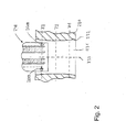
- An example of a highly accurate dimensional survey a finely drilled hole is determined by Fig. 2 explained in more detail.
- this time is also used to acquire bore measurement signals, so that, for example, the measurement takes place at least temporarily at the same time as the delivery of the processing tools to the honing tool.
- the measurement may extend without interruption to the initial phase of the material-removing machining, so that, where appropriate, takes place a seamless transition between the detection of the bore measurement signal for output control of Feinbohroperation and an in-process measurement of subsequent honing.
- the measuring device 160 of the honing device is used immediately after completion of Feinbohroperation and before the beginning of the material-removing honing operation as output control for checking the processing result of Feinbohroperation and at the same time as input control for the subsequent honing operation. If the bore measurement signal indicates that the finely drilled hole macro-shape obtained by the fine boring is not within a predetermined tolerance range, the operation of the fine boring device can be controlled, for example, by adjusting the radial stop position of the drill bit tip 129 such that during the subsequent machining of a next workpiece the resulting macro-shape of the well drilled hole is in the desired tolerance after completion of the fine boring operation.
- the pre-honing operation performed by the first honing unit 141A begins with the inner surface 132 of the bore 131 having a surface structure (with crossed processing marks) changed from the fine boring and a macro-shape closer to the target shape larger inner diameter receives.
- the processing result of the pre-honing operation can be checked during the pre-honing and / or after completion of the pre-honing with the aid of the measuring device 160.
- the pre-honing operation can be terminated on the basis of the corresponding measurement signal if the macro-form aspired after pre-honing or the desired diameter of the bore after pre-honing is reached.
- the first honing tool 148A is extended out of the bore and the workpiece is moved to a machining position associated with the second honing unit 141B, which permits insertion of the second honing tool 148B into the bore.
- the material-removing prefabricated honing operation is carried out, through which the bore receives the desired desired shape and surface structure.
- the finished honing operation can also be monitored with the aid of a measuring device and optionally controlled in dependence on a corresponding measuring signal.
- the workpiece Upon completion of the finish honing operation and retraction of the second honing spindle from the workpiece, the workpiece is moved toward the gauge 170, which is adapted to measure the finished machined bore 131 and check to see if the diameter, macro-shape of the bore 131, and / or the surface texture of the inner surface 132 satisfies the specifications of the machining process.
- the gauge 170 is adapted to measure the finished machined bore 131 and check to see if the diameter, macro-shape of the bore 131, and / or the surface texture of the inner surface 132 satisfies the specifications of the machining process.
- FIG Fig. 2 An example of a highly accurate dimensional measurement of a finely drilled bore 231 in a workpiece 230 will be made with reference to FIG Fig. 2 explained in more detail.
- the ideally circular cylindrical inner surface 232 has received a significantly different from a circular cylindrical shape form with a waist in the axial central region of the bore and with diameter extensions to the respective open end portions of the bore by the Feinbohrrind.
- the honing tool 248 is lowered into the bore 231 until the diametrically opposed air measuring nozzles 261A, 261B of the measuring device reach a measuring plane Z3 in the vicinity of the spindle-facing, upper input region of the bore 231 to have.
- the honing tool 248 is rotated in the bore substantially symmetrically about the bore axis 233 by at least 180 ° to determine the diameter of the bore on plane Z3.
- a rotary encoder for the honing spindle it is possible to detect the rotational angle values of the honing tool assigned to the diameter values, so that an angular resolution measurement of the diameter in the region of the respective measuring plane is also possible. From this, information about the bore shape in the measuring plane can be derived.
- the honing tool is lowered further, so that the measuring sensors 261A, 261 B lie in the axial central region of the bore at the measuring plane Z2.
- the corresponding, optionally angle-resolving diameter measurement process is repeated.
- a third measurement then takes place on plane Z1 in the vicinity of the spindle end facing away from the bore.
- the measurement results are evaluated to determine the macro-shape of the hole. If this evaluation reveals that the macro-shape is outside the specification specified in the fine-boring process, the fine-boring tool is readjusted or replaced by displacement of the drill bit so as to obtain a macro-shape of the drilled hole within the specification on the subsequent workpiece.
- a double-jointed rod is provided for coupling the honing tool used for the input machining to the honing spindle, wherein a drive rod via an upper (or first) joint to the honing spindle and the honing tool via a lower (or second) Joint can be coupled to the drive rod.
- the processing equipment is designed so that only a further drilling, especially a rough drilling with a rough drilling tool is provided before the Ninfeinbohrbearbeitung for the machining of the hole.
- a further preferred embodiment of the processing plant provides that the fine boring tool used in the output fine boring has one or more aus Kunststoffbarer cutting and one or more fixed cutting, which are axially offset in relation to each other so that the fixed cutting in a running into the bore Advance forward stroke.
- the machining system is designed such that the fine boring tool used in the output fine boring has a plurality of circumferentially offset, ausberichterbare cutting and no fixed cutting edge, preferably five controllable cutting are provided.
- a two-cutting process is provided using a Feinbohrtechnikmaschines with at least one controllable and at least one fixed cutting edge, wherein at a running into the bore forward stroke the ausnchbare cutting withdrawn and only the fixed blade is in engagement with the bore and at a running out of the bore backward stroke the controllable cutting edge is extended so that only the austouredbare cutting edge is in engagement with the bore.
- a laser unit can be integrated to perform a surface structuring by means of laser radiation. Laser irradiation can also be used to convert near-surface areas of the machined workpiece surface over a large area by energy input, for example, to harden. It may also be integrated a brushing device for brushing the surfaces.
- the production of defined surface structures and other defined surface properties can be completely dispensed with the classic honing, for example, by one or more of the above-mentioned methods for final surface finishing in the honing device can be used.
- the terms "honing device” and “honing tool” are thus representative of finishing procedures or finishing tools that can be used after a Feinbohroperation to edit the finely drilled bore machined or without chip removal and bring in a desired final state.
- the honing device is multi-level, e.g. formed two- or three-stage and therefore includes a corresponding number of successively arranged honing units, which are also redundant executable.
Applications Claiming Priority (2)
| Application Number | Priority Date | Filing Date | Title |
|---|---|---|---|
| DE102011008754 | 2011-01-17 | ||
| DE102011000348A DE102011000348A1 (de) | 2011-01-26 | 2011-01-26 | Verfahren zur kombinierten Feinbohr- und Honbearbeitung sowie Bearbeitungsanlage zur Durchführung des Verfahrens |
Publications (2)
| Publication Number | Publication Date |
|---|---|
| EP2476510A2 true EP2476510A2 (fr) | 2012-07-18 |
| EP2476510A3 EP2476510A3 (fr) | 2013-04-17 |
Family
ID=45558518
Family Applications (1)
| Application Number | Title | Priority Date | Filing Date |
|---|---|---|---|
| EP12151462.4A Withdrawn EP2476510A3 (fr) | 2011-01-17 | 2012-01-17 | Procédé de rodage et de perçage de précision combinés ainsi qu'installation de traitement destinée à la réalisation du procédé |
Country Status (4)
| Country | Link |
|---|---|
| US (1) | US20120184182A1 (fr) |
| EP (1) | EP2476510A3 (fr) |
| KR (1) | KR20120083232A (fr) |
| CN (1) | CN102581618A (fr) |
Families Citing this family (11)
| Publication number | Priority date | Publication date | Assignee | Title |
|---|---|---|---|---|
| DE102011079900A1 (de) * | 2011-07-27 | 2013-01-31 | Grob-Werke Gmbh & Co. Kg | Verfahren und Bearbeitungsanlage zum Feinbearbeiten einer Kurbelwellenlagerbohrung |
| DE102013204714A1 (de) * | 2013-03-18 | 2014-10-02 | Elgan-Diamantwerkzeuge Gmbh & Co. Kg | Honverfahren und Honwerkzeug |
| CN103953547B (zh) * | 2014-04-30 | 2016-08-24 | 宁波甬微集团有限公司 | 压缩机滑片的制造方法 |
| DE102014210012A1 (de) * | 2014-05-26 | 2015-11-26 | Elgan-Diamantwerkzeuge Gmbh & Co. Kg | Honverfahren zur Feinbearbeitung von Bohrungen |
| US20170182630A1 (en) * | 2014-05-27 | 2017-06-29 | Mauser-Werke Obergndorf Maschinenbau GmbH | Fine Machining Method and Machine Tool Unit |
| DE102015101383A1 (de) * | 2015-01-30 | 2016-08-04 | Mauser-Werke Oberndorf Maschinenbau Gmbh | Bohrkopf, Spindel mit Bohrkopf und Verfahren zum Feinbearbeiten |
| SE539320C2 (en) * | 2015-11-13 | 2017-06-27 | Chris-Marine Ab | Arrangement and method for maintenance of a cylinder liner in an engine |
| KR101720883B1 (ko) * | 2015-12-31 | 2017-04-03 | 신성대학 산학협력단 | 내경 정밀 보링 가공장치 |
| DE102016105717A1 (de) * | 2016-03-29 | 2017-10-05 | Gehring Technologies Gmbh | Verfahren zur Herstellung rotationssymmetrischer, nicht zylindrischer Bohrungen mit einem Honwerkzeug |
| US10675729B2 (en) * | 2017-05-31 | 2020-06-09 | Baker Hughes, A Ge Company, Llc | Electromechanical rotary pipe mill or hone and method |
| DE102017210187A1 (de) * | 2017-06-19 | 2018-12-20 | Elgan-Diamantwerkzeuge Gmbh & Co. Kg | Honverfahren und Bearbeitungsmaschine zum Konturhonen |
Citations (1)
| Publication number | Priority date | Publication date | Assignee | Title |
|---|---|---|---|---|
| WO2008009411A1 (fr) | 2006-07-19 | 2008-01-24 | Nagel Maschinen- Und Werkzeugfabrik Gmbh | Procédé d'usinage combiné par perçage de précision et rodage ainsi qu'installation d'usinage pour la mise en œuvre du procédé |
Family Cites Families (12)
| Publication number | Priority date | Publication date | Assignee | Title |
|---|---|---|---|---|
| US3286409A (en) * | 1964-03-27 | 1966-11-22 | Barnes Drill Co | Honing machine |
| US4924637A (en) * | 1987-10-21 | 1990-05-15 | Ngk Insulators, Ltd. | Method of machining ceramic rotor for pressure wave type supercharger |
| DE19601158C1 (de) * | 1996-01-15 | 1997-06-26 | Daimler Benz Ag | Gehonte Zylinderbohrung eines Hubkolben-Verbrennungsmotors und Verfahren zu ihrer Herstellung |
| US7346973B2 (en) * | 2002-09-09 | 2008-03-25 | Nissin Manufacturing Co., Ltd. | Processing cell of automatic machining system and automatic honing system |
| SE524349C2 (sv) * | 2002-10-07 | 2004-07-27 | Skf Ab | En metod för samtidig bearbetning och mätning av parametrar hos en yta som utsättes för maskinbearbetning |
| US7027145B2 (en) * | 2003-06-24 | 2006-04-11 | The Regents Of The University Of Michigan | Reconfigurable surface finish inspection apparatus for cylinder bores and other surfaces |
| DE10348419C5 (de) * | 2003-10-14 | 2011-06-30 | Gehring Technologies GmbH, 73760 | Verfahren zum Schrupphonen der Mantelfläche einer Bohrung |
| CA2548927C (fr) * | 2004-09-07 | 2012-03-20 | Sunnen Products Company | Systeme d'alimentation pour une machine a roder les cylindres disposant d'un controle complet de la force, de la vitesse et de la position d'avance et procede correspondant |
| EP1932620B1 (fr) * | 2006-12-12 | 2010-09-29 | Nagel Maschinen- und Werkzeugfabrik GmbH | Procédé de finissage des surfaces internes d'alésages et dispositif de finition adapté |
| US7874893B2 (en) * | 2007-06-07 | 2011-01-25 | Nissan Motor Co., Ltd. | Honing method and honing control device |
| JP5208669B2 (ja) * | 2008-10-22 | 2013-06-12 | 株式会社ジェイテクト | 中ぐり加工装置および穴加工方法 |
| EP2432612B1 (fr) * | 2009-05-22 | 2017-01-11 | Sunnen Products Company | Procédé automatique de finition de forages |
-
2012
- 2012-01-16 KR KR1020120004805A patent/KR20120083232A/ko not_active Application Discontinuation
- 2012-01-17 EP EP12151462.4A patent/EP2476510A3/fr not_active Withdrawn
- 2012-01-17 US US13/351,523 patent/US20120184182A1/en not_active Abandoned
- 2012-01-17 CN CN2012100133324A patent/CN102581618A/zh active Pending
Patent Citations (1)
| Publication number | Priority date | Publication date | Assignee | Title |
|---|---|---|---|---|
| WO2008009411A1 (fr) | 2006-07-19 | 2008-01-24 | Nagel Maschinen- Und Werkzeugfabrik Gmbh | Procédé d'usinage combiné par perçage de précision et rodage ainsi qu'installation d'usinage pour la mise en œuvre du procédé |
Also Published As
| Publication number | Publication date |
|---|---|
| KR20120083232A (ko) | 2012-07-25 |
| CN102581618A (zh) | 2012-07-18 |
| EP2476510A3 (fr) | 2013-04-17 |
| US20120184182A1 (en) | 2012-07-19 |
Similar Documents
| Publication | Publication Date | Title |
|---|---|---|
| EP2040881B1 (fr) | Procédé d'usinage combiné par perçage de précision et rodage ainsi qu'installation d'usinage pour la mise en oeuvre du procédé | |
| EP2476510A2 (fr) | Procédé de rodage et de perçage de précision combinés ainsi qu'installation de traitement destinée à la réalisation du procédé | |
| EP1932620B1 (fr) | Procédé de finissage des surfaces internes d'alésages et dispositif de finition adapté | |
| EP1907156B1 (fr) | Procede d'usinage de precision d'arbres-manivelles et centre d'usinage correspondant | |
| DE112007000560B4 (de) | Werkzeugkopf, Werkzeugmaschine und Bohrverfahren zum Bohren eines Zylinderblocks unter Verwendung der Werkzeugmaschine | |
| DE102010010901B4 (de) | Verfahren und Vorrichtung zum Feinbearbeiten einer Kurbelwellenlagerbohrung | |
| DE102011079900A1 (de) | Verfahren und Bearbeitungsanlage zum Feinbearbeiten einer Kurbelwellenlagerbohrung | |
| EP2569119B1 (fr) | Procédé d'usinage d'un alésage de cylindre à l'aide de taillants géométriquement déterminés et géométriquement indéterminés | |
| DE10219441C1 (de) | Verfahren zur Herstellung von innen- und/oder außenprofilierten Ringen sowie Anordnung hierzu | |
| EP2570230A2 (fr) | Procédé et dispositif de finition de pièces à usiner | |
| EP2570229A2 (fr) | Procédé et dispositif de finition de pièces à usiner | |
| WO2013174487A2 (fr) | Dispositif et procédé d'usinage d'une pièce optique | |
| DE102006014972B4 (de) | Kombiniertes Bearbeitungsverfahren und Bearbeitungseinrichtung | |
| DE102011000348A1 (de) | Verfahren zur kombinierten Feinbohr- und Honbearbeitung sowie Bearbeitungsanlage zur Durchführung des Verfahrens | |
| EP3148745B1 (fr) | Procédé de rodage pour l'usinage de trous | |
| DE102014225295A1 (de) | Mess-lünette zum abstützen und vermessen von zentrischen werkstückbereichen, schleifmaschine mit einer derartigen mess-lünette sowie verfahren zum abstützen und vermessen von zentrischen werstückbereichen | |
| DE19743139A1 (de) | Vorrichtung zum Durchführen eines Schleifvorganges und Verfahren dazu | |
| WO2020011541A1 (fr) | Procédé de rodage et machine d'usinage pour le rodage de contours | |
| EP3148743A1 (fr) | Procédé d'usinage d'alésages de roulements ou de perçages de guidage et dispositif de mise en oeuvre de ce procédé | |
| DE102018206113A1 (de) | Feinbearbeitungsverfahren zum Herstellen einer nicht-kreiszylindrischen Bohrung sowie Feinbearbeitungssystem und Schleifwerkzeugeinheit | |
| DE102016112254A1 (de) | Verfahren für zylindrisches Schleifen und Maschine für zylindrisches Schleifen | |
| EP3148744A1 (fr) | Procédé d'usinage de précision et unité machine-outil | |
| DE202006020974U1 (de) | Bearbeitungsanlage zur kombinierten Feinbohr- und Honbearbeitung | |
| EP0575657B1 (fr) | Méthode et machine pour l'usinage au fouesse du perçages dans des pièces à usiner | |
| DE102022104927A1 (de) | Kombinationswerkzeug und Verfahren zur Feinbearbeitung von Bohrungen |
Legal Events
| Date | Code | Title | Description |
|---|---|---|---|
| PUAI | Public reference made under article 153(3) epc to a published international application that has entered the european phase |
Free format text: ORIGINAL CODE: 0009012 |
|
| AK | Designated contracting states |
Kind code of ref document: A2 Designated state(s): AL AT BE BG CH CY CZ DE DK EE ES FI FR GB GR HR HU IE IS IT LI LT LU LV MC MK MT NL NO PL PT RO RS SE SI SK SM TR |
|
| AX | Request for extension of the european patent |
Extension state: BA ME |
|
| PUAL | Search report despatched |
Free format text: ORIGINAL CODE: 0009013 |
|
| AK | Designated contracting states |
Kind code of ref document: A3 Designated state(s): AL AT BE BG CH CY CZ DE DK EE ES FI FR GB GR HR HU IE IS IT LI LT LU LV MC MK MT NL NO PL PT RO RS SE SI SK SM TR |
|
| AX | Request for extension of the european patent |
Extension state: BA ME |
|
| RIC1 | Information provided on ipc code assigned before grant |
Ipc: B24B 33/02 20060101ALI20130313BHEP Ipc: B23Q 15/04 20060101AFI20130313BHEP |
|
| 17P | Request for examination filed |
Effective date: 20131016 |
|
| RBV | Designated contracting states (corrected) |
Designated state(s): AL AT BE BG CH CY CZ DE DK EE ES FI FR GB GR HR HU IE IS IT LI LT LU LV MC MK MT NL NO PL PT RO RS SE SI SK SM TR |
|
| 17Q | First examination report despatched |
Effective date: 20160726 |
|
| STAA | Information on the status of an ep patent application or granted ep patent |
Free format text: STATUS: THE APPLICATION IS DEEMED TO BE WITHDRAWN |
|
| 18D | Application deemed to be withdrawn |
Effective date: 20161206 |