EP2474342B1 - Übungsvorrichtung zum Gewichtheben und andere Fitness-Aktivitäten - Google Patents
Übungsvorrichtung zum Gewichtheben und andere Fitness-Aktivitäten Download PDFInfo
- Publication number
- EP2474342B1 EP2474342B1 EP12150328.8A EP12150328A EP2474342B1 EP 2474342 B1 EP2474342 B1 EP 2474342B1 EP 12150328 A EP12150328 A EP 12150328A EP 2474342 B1 EP2474342 B1 EP 2474342B1
- Authority
- EP
- European Patent Office
- Prior art keywords
- weight
- exercise device
- section
- axial end
- face
- Prior art date
- Legal status (The legal status is an assumption and is not a legal conclusion. Google has not performed a legal analysis and makes no representation as to the accuracy of the status listed.)
- Not-in-force
Links
Images


Classifications
-
- A—HUMAN NECESSITIES
- A63—SPORTS; GAMES; AMUSEMENTS
- A63B—APPARATUS FOR PHYSICAL TRAINING, GYMNASTICS, SWIMMING, CLIMBING, OR FENCING; BALL GAMES; TRAINING EQUIPMENT
- A63B21/00—Exercising apparatus for developing or strengthening the muscles or joints of the body by working against a counterforce, with or without measuring devices
- A63B21/06—User-manipulated weights
- A63B21/072—Dumb-bells, bar-bells or the like, e.g. weight discs having an integral peripheral handle
- A63B21/0724—Bar-bells; Hand bars
-
- A—HUMAN NECESSITIES
- A63—SPORTS; GAMES; AMUSEMENTS
- A63B—APPARATUS FOR PHYSICAL TRAINING, GYMNASTICS, SWIMMING, CLIMBING, OR FENCING; BALL GAMES; TRAINING EQUIPMENT
- A63B21/00—Exercising apparatus for developing or strengthening the muscles or joints of the body by working against a counterforce, with or without measuring devices
- A63B21/06—User-manipulated weights
- A63B21/072—Dumb-bells, bar-bells or the like, e.g. weight discs having an integral peripheral handle
- A63B21/0726—Dumb bells, i.e. with a central bar to be held by a single hand, and with weights at the ends
-
- A—HUMAN NECESSITIES
- A63—SPORTS; GAMES; AMUSEMENTS
- A63B—APPARATUS FOR PHYSICAL TRAINING, GYMNASTICS, SWIMMING, CLIMBING, OR FENCING; BALL GAMES; TRAINING EQUIPMENT
- A63B71/00—Games or sports accessories not covered in groups A63B1/00 - A63B69/00
-
- A—HUMAN NECESSITIES
- A63—SPORTS; GAMES; AMUSEMENTS
- A63B—APPARATUS FOR PHYSICAL TRAINING, GYMNASTICS, SWIMMING, CLIMBING, OR FENCING; BALL GAMES; TRAINING EQUIPMENT
- A63B71/00—Games or sports accessories not covered in groups A63B1/00 - A63B69/00
- A63B71/0054—Features for injury prevention on an apparatus, e.g. shock absorbers
- A63B2071/0063—Shock absorbers
Definitions
- the present invention relates to an exercise device and in particular to a dumbbell or barbell, for weightlifting and other fitness activities. More specifically it relates to the configuration of the weight sections mounted to the lifting handle in such exercise devices.
- dumbbells or barbells comprise a handle bar and weights (heads) mounted on the ends of the bar.
- the dumbbell is conventionally lifted by the handle bar in order to train specific muscles groups, and/or increase muscle mass.
- the weights are generally permanently fixed to the bar.
- a further problem associated with conventional dumbbells or barbells arises when they are dropped to the floor after use.
- US patent number US 4361324 and Chinese utility model applications CN2167738 and CN 20062045127 disclose dumbbells with rubber outer covers with tread patterns extending circumferentially around the entire circumference of the weight sections. The tread and rubber cover provides some cushioning and in the case of CN 2167738 are described as providing some anti-sliding function.
- US 5250014 also describes a dumbbell with a cushioning plate with a series of projections extending around the entire circumference of the dumbbell. These arrangements can however be improved both in terms of aesthetics, and in providing improved functionality in terms of use by a user and improved cushions and grip, as well as more generally.
- KR 200437442 provides a tyre-tread type pattern on the outer surface of the weight head to provide an improved anti-sliding function.
- dumbbell which can be used in a wider range of exercises, and which is able to better withstand frequent use, and in particular withstand repeated impact from dropping, and reduces the likelihood of damage to other equipment.
- the present invention therefore aims to provide a dumbbell which obviates or mitigates the above described problems and/or which provides improvements generally or an alternative to such existing arrangements.
- the heads of the dumbbells are modified in such a manner so as to allow the heads themselves to be held and gripped for the purpose of executing a greater variety of exercises.
- the weight distribution of the dumbbells is greatly altered and many more exercises can be carried out using the same device.
- the head is moulded to the shape of the inside of the palm of the user's hands and slots need to be made at certain positions in the periphery of the head to enhance finger and hand grip.
- space needs to be allowed at the end face of the dumbbell head to allow room for comfortable thumb positioning and flats need to be inserted on the inner face of the dumbbell heads to allow for alternative finger grips when lifting the dumbbells from a vertical position on the floor.
- the plurality of slots are disposed only in discrete circumferential regions of the periphery of the weight section. Providing slots and a pattern only in a discrete circumferential region of the circumference of the weight section better defines, both visually and functionally, a particular grip region for a user to grip and hold the weight section and dumbbell for certain exercises.
- the flats on the inner axial end faces of the dumbbell heads allow additional finger grips to hold the head firmly when performing exercises with the dumbbell.
- the slots and the curved shape of the dumbbell head are configured to form a grip portion for a user to grip and hold the weight section within the palm of the user's hands.
- the thumb /finger recesses at each end of the head further defines a grip portion for holding the weight section, with a user's thumbs being able to fit into the recesses.
- the flats formed on the inner surfaces of the dumbbell heads provide alternative finger grips providing a variety of gripping points so extending the range of exercises that can be performed with the device. This improves a user's grip of the weight section, as well as more clearly indicating where and how a user can hold the weight section and dumbbell.
- the weight heads of the dumbbell have a curved shape. This can be contrasted with the sharp corners of conventional dumbbells and spreads the load over a larger curved area of the dumbbell head as in a rubber ball rather than impacting on sharp corners.
- the curved shape and ends of the dumbbell heads also improves the impact absorption properties of the outer skin by greater distribution of the impacted area and hence of the weight section and exercise device, thereby providing a "softer" impact in the area of the dumbbell head that is most susceptible to impact in use.
- This softer impact reduces jarring of the weight section, and of the fixings between the weight section and the handle of the exercise device to which the weight section is mounted, thereby mitigating the risk of loosening of the weight heads, mitigating damage to the weight section, and reducing damage to the exercise device, for example dumbbell generally, and to other equipment.
- the dumbbell however has a flat surface incorporated into the shape of the head which will prevent the dumbbell from rolling on the floor and will allow the dumbbell to be used for exercises such as press-ups.
- the flattened peripheral section of the dumbbell head varies the outer circumference surface of the dumbbell circumferential around the dumbbell such that the dumbbell will tend to rest in a particular circumferential position when placed on the ground. This assists in preventing the dumbbell from rolling when placed on the ground. Furthermore this also provides the weight sections with increased surface grip preventing the dumbbells from rolling or from slipping against the ground when a user places their weight on them, for example to perform push-ups.
- the weight section may comprise an inner weight section comprising a cast metal weight.
- the outer skin and resilient projections may be formed from polyurethane or rubber or any similar material.
- the slots, thumb-grip and flattened section may be integrally formed with and from the outer skin. This allows the recess to be most easily formed with a simple cast inner weight section core which does not include such a recess. Integrally forming the grip slots and other features from the outer skin also enables these important features to be formed in the same manufacturing step as the skin, thereby simplifying manufacture. In addition, the features are thus securely connected to the outer skin. In addition it provides a relatively flexible and soft shoulder area surrounding the recesses on the outer end faces improving grip and comfort to a user.
- an exercise device for example a dumbbell or barbell, for weightlifting and other fitness activities.
- the device comprises a lifting bar having an axis and opposed axial ends, and a pair of weight sections mounted spaced apart on the respective opposed axial ends of the lifting bar with the lifting bar extending between the spaced apart weight sections.
- Each weight section has an outer circumferential surface, an inner axial end face facing the inner axial end face of the other weight section mounted on the opposite end of the lifting bar, and an outer axial end face.
- the circumferential surface of at least one of the weight sections comprises a plurality of elongate channels each extending generally circumferentially around only part of the outer circumferential surface of the weight section and spaced substantially axially from an adjacent elongate channel axially along the outer circumferential surface of the weight section.
- the elongate channels are preferably sized and spaced to substantially match a typical user's finger.
- At least one of the elongate channels preferably extends a different circumferential distance around the weight section to at least one of the other grooves.
- the plurality of elongate channels comprise two sets of elongate channels disposed on substantially diametrically opposite sides of outer circumferential surface of the weight section.
- each set of grooves may comprise three or more spaced apart elongate channels in each set.
- a central groove of the three spaced apart elongate channels in each set preferably extends circumferentially further than the adjacent elongate channels on either side of the central groove.
- Each weight section may preferably have a barrelled or curved circumferential outer surface having a central portion at greater radius from lifting bar than axial inner and outer end portions.
- the outer circumferential surface of each weight section may be curved to match an inner palm surface of a typical user's hand.
- the outer circumferential surface includes a substantially flat portion.
- At least one section of the inner axial end face of at least one of the weight sections is preferably recessed from a remainder portion of the inner axial end face.
- the inner axial end face of at least one of the weight sections preferably includes two recessed sections disposed on diametrically opposite sides of the inner axial end face.
- An outer axial end of at least one of the weight sections may be recessed from a remainder portion of the outer axial end face.
- the weight sections comprise an inner weight section about which is moulded an outer skin.
- the outer skin may comprise a polyurethane or rubber skin.
- the elongate channels are preferably integrally formed within the outer skin.
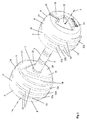
- a dumbbell 1 comprises a lifting bar 2 having an axis 3.
- First and second weight sections 4 are mounted spaced apart on the respective opposed axial ends of the lifting bar 2.
- the lifting bar 2 extends between the spaced apart weights sections 2.
- the bar 2 comprises a central handle portion 5, configured to enable a user to conventionally grip the bar 2 to lift the weight sections 4 and dumbbell 1 conventionally.
- the bar 2 is preferably formed from stainless or carbon steel which may be plated or covered in material such as rubber or polyurethane, but may be made from man-made material such as polyurethane to improve grip.
- the weight sections 4 preferably comprise an inner weight section (not shown) formed from cast iron, although any other suitable material may be used.
- An outer skin 6 of polyurethane or rubber material is formed about the inner weight section. Specifically, the outer skin 6 is moulded about the inner weight section.
- cast iron typically comprises a low quality surface finish
- the outer skin 6 provides the weight section 4 with an improved visual appearance.
- the resilient and compressible material properties of the polyurethane outer skin 6 act to protect the inner weight section from damage, and provide limited impact absorption.
- coating the inner weight section with an outer skin 6 protects the cast iron from corrosion, and mechanical damage.
- the weight sections 4 are generally substantially cylindrical in shape having a preferably centrally located mounting bore 7 configured to receive an end of the bar 2, and mount the weight sections 4 coaxially with an axis 3 of the bar 2.
- the mounting bore 7 may be formed in the inner weight section during the casting processing or may be machined after casting. Alternatively, and preferably the inner weight section may be cast about a collar (not shown) defining the inner bore 7.
- the inner bore 7 is toleranced to provide an interference fit, to prevent rattle between the bar 2 and the inner weight section.
- the weight sections 4 are welded into position on the ends of the bar or attached in other known ways.
- Each weight section 4 has an outer circumferential surface 8 extending around the weight section radially spaced from the axis 3 having an axial width in a direction parallel to the axis 3.
- Each weight section 4 furthermore has two generally opposed axial end faces 10,11 comprising an outer axial end face 10 and an inner axial end face 11.
- the inner axial end faces 11 are adjacent the handle portion 5 and faces the corresponding inner axial end face 11 of the other weight section 4 when the weight sections 4 are mounted upon the lifting bar 5.
- the axial end faces 10, 11 extend generally perpendicular to the axis 3.
- the outer circumferential peripheral surface 8 of the weight sections 4 include a plurality of elongate channels 12 which are formed in the outer circumferential surface 8 of the weight section.
- the elongate channels are formed in the outer circumferential surface 8 of the weight section extending in a generally circumferential direction.
- the elongate channels 12 however only extend partway around the circumferential surface 8 and weight section 4.
- Each of the individual elongate channels 12 are located at a respective axial distance across the width of the weight section 4 with the elongate channels 12 preferably parallel to each other spaced axially and axially aligned with respect to the weight section 4. In other embodiments they may however extend around the circumference at an angle to an axial plane and/or at angles to each other.
- each set of elongate channels 13,14, and the elongate channels 12 extend approximately around one quarter to one third of the distance around the circumference of the weight section 14.
- the elongate channels 12 are formed about the circumferential surface 8 to increase grip in use by increasing surface roughness.
- the shape and position of the elongate channels 12 are such that they also assist the user to grip the dumbbell weight head 4.
- the sets 13,14 of elongate channels 12 also define, both visually and functionally, a particular grip region for a user to grip and hold the weight section 4 and dumbbell 1 for certain exercises. Examples of such alternative grips enabled and which can be used by a user with the dumbbell 1 are shown in Figures 6 to 9 . It will however be appreciated that other grips may also be utilised. This increases the functionality of the dumbbell 1 by enabling it to be more effectively and safely gripped by the weight sections 4, and therefore used to perform an increased and varied number of weightlifting and exercise operations. In particular, grasping the dumbbell 1 by the weight sections 4 requires an alternative grip, and therefore forces the user to lift the dumbbell 1 in a different way, using different muscle groups.
- Each of the sets 13,14 of elongate channels 12 comprise three individual elongate channels 12a, 12b, 12c disposed parallel and spaced apart from each other with a central elongate channels 12b disposed generally in the centre of the axial width of the circumferential surface 8 and the other two side elongate channels 12a,12c disposed either side of it.
- the central groove 12c preferably extends slightly further than the side elongate channels 12a, 12c so as to easily accommodate a user's slightly longer index finger when gripping the weight as for example shown in Figures 6 and 7 , and with these other two fingers easily falling within the adjacent grooves.
- the grooves are spread apart from each other as it is generally corresponding to the spacing of a typical user's fingers.
- Each of the elongate channels 12 has a curved radiussed profile preferably shaped to readily accommodate a typical user's finger and for example has a width in the region of 10 to 20 mm and a resulting depth of in the region of 5 to 10 mm. In other embodiments however the elongate channels 12 may be smaller and narrower simply providing a roughened area and recess portions to increase the grip in the specific regions.
- the elongate channels 12 are also axially spaced apart with the centres of the elongate channels 12a,12b,12c typically between 15 to 40 mm apart.
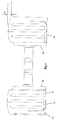
- each of the weight sections 4 is also preferably curved in a generally axial direction as more clearly shown in Figures 2 to 4 with the outer peripheral surface 8 and weight sections 4 having a barrelled barrel shaped outer surface.
- the profile of the peripheral surface 8 of the weight section 4 is dimensioned to comfortably fit within a user's hand when gripping the weight head 4 on the other side as for example shown in Figures 6 and 7 and makes it more comfortable for a user to grasp the weight head 4.
- the projecting central portion also improves a user's grip of the weight head 4 by providing a central rib which assists in preventing the weight head 4 from slipping from the user's hand when for example being held as shown in Figure 6 with the central 'bulge' fits within a user's cupped hands.
- the central portion of the outer circumferential surface 8 of each weight head 4 is generally at a greater radius from the axis 3 than axial end portions of the circumferential outer surface 8 with the central portion projecting a distance d for example 5 mm further radially outward.
- the outer circumferential surface 8 of the weight heads 4 also preferably further includes a flattened section 17 such that the weight section 4 is not entirely symmetrical about the axis 3.
- This flattened section 17 preferably corresponds to one of the sections 16 between the sets of elongate channels 13,14 and preferably extends across the entire axial width of the outer circumferential surface 8 of the weight section 4.
- This flattened section 17 forms a base of the dumbbell 1 with both weight heads 4 being aligned such that the flattened sections 17 are aligned and allow the dumbbell 1 to be placed stably on the ground without rolling.
- the flattened section 17 also provides increased traction between the dumbbell 1 and the floor when the dumbbell 1 is placed on the floor and so enables a user to support their weight on the dumbbell 1 and bar 2 for example to perform push ups while limiting the risk of the dumbbell 1 from slipping underneath them. This allows the dumbbell 1 to be used in yet further exercises with the dumbbell 1 handle 5 providing a handle on the floor that can be gripped.
- the respective inner axial end faces of the weight sections 4 include two diametrically opposed recess sections 18 which are axially set back from the end 19 of the axial end face 11.
- the recess portions 18 in this embodiment comprise chordal sections of the axial end of the weight head 4, and are arranged at an angle to each other and leaving a central triangular portion 20 therebetween.
- the recessed sections 18 are preferably circumferentially aligned with the respective sets 13,14 of elongate channels 12 with a base of the triangular section 20 aligned with the flattened section 17 of the weight heads 4.
- the recess sections 18 provide as for example shown in Figure 7 suitable space for a user's thumbs to be located when gripping the weight head 4.
- a shoulder portion 21 along the edge of the triangle section 20 and recessed portion 18 also provides a lip against which a user's thumb can rest.
- the recesses 18 also provide sufficient room for a user's fingers to be located when gripping the weight head 4 as for example shown in Figure 9 . It will be appreciated that in other embodiments different shapes of recesses 18 in the axial inner end face 11 could be provided to similarly accommodate a user's thumb or finger when gripping the dumbbell weight head 4.
- the outer axial end face 10 of the weight sections 4 preferably includes a central recessed portion 22.
- this recessed section 22 is also generally triangular shape aligned with the triangular section 20 on the inner axial end face 11 and flattened region 17 on the bottom of the weight head 4.
- This recessed portion 22 defines a shoulder lip 23 in the outer axial end face 10 which a user can furthermore grip improving the grip of the weight head 4 with the user's thumb or finger resting in the recess 22 and against this shoulder 23. This again further improves the user's ability to grip the weight head 4 and the end of the dumbbell 1.
- the outer axial end face 10 also includes a generally radially extending slot 24 which is preferably sized to receive a user's finger or hand and provides a further location and feature enabling a user to grip the end of the weight head 4.
- the barrelling of the outer profile of the weight heads 4 provides the weight heads 4 with a curved and rounded profile without any sharp edging which reduces impact damage if and when the dumbbell 1 is dropped on a floor and/or against other objects.
- the elongate channels 12 and recesses 18,22 within the outer peripheral surface of the weight heads 4 are preferably all formed within the moulded outer skin 6 of the weight head 4 and are integral therewith.
- the outer skin 6 is preferably formed about the inner weight section by a moulding operation using a mould (not shown) into which the inner weight section is placed with the mould surrounding the inner weight section.
- the mould defines a mould cavity between the inner weight section and an inner mould surface corresponding to the outer skin 6.
- a material, such as polyurethane, is then injected into the mould cavity, where it forms about the inner weight section. In this way an outer skin 6 having the plurality of elongate channels 12 is formed about and moulded onto the inner weight section.
- the mould may in particular comprise two mould sections, or mould halves.
- the two mould halves may be further fitted into an outer mould section to hold them together during moulding.
- the mould halves each comprise an inner surface having a configuration including projections shaped to define the elongate channels 12.
- the mould halves are split along a longitudinal plane passing though the axis of the weight section 4. The mould halves can thereby be separated and the mould split open to allow the weight head 4 with moulded outer covering 6 to be removed.
- the weight sections 4 in this embodiment are generally cylindrical, excepting the barrelling and localised flat portion 17, and have a generally circular outer circumference.
- the weight sections 4 may have other shapes while still having a generally circumferential surface and central axis.
- the weight sections 4, bar 2 upon which the weight sections 4 are mounted do not need to be coaxial with the central axis 3. While each of the weight sections 4 are preferably substantially identical in other embodiments they may be different and for example only one of the weight sections 4 may include the elongate channels 12.
Landscapes
- Health & Medical Sciences (AREA)
- General Health & Medical Sciences (AREA)
- Physical Education & Sports Medicine (AREA)
- Life Sciences & Earth Sciences (AREA)
- Biophysics (AREA)
- Orthopedic Medicine & Surgery (AREA)
- Rehabilitation Tools (AREA)
- Motorcycle And Bicycle Frame (AREA)
Claims (13)
- Übungsvorrichtung zum Gewichtheben und für andere Fitnessaktivitäten, die Folgendes umfasst:eine Hantelstange (2), die eine Achse (3) und gegenüberliegende axiale Enden aufweist; undein Paar Gewichtsbereiche (4), die voneinander beabstandet an den jeweiligen gegenüberliegenden axialen Enden der Hantelstange (2) befestigt sind,wobei sich die Hantelstange (2) zwischen den voneinander beabstandeten Gewichtsbereichen (4) erstreckt, wobei jeder Gewichtsbereich (4) eine Außenumfangsfläche (8), eine innere axiale Endfläche (11), die zu der inneren axialen Endfläche des an dem gegenüberliegenden Ende der Hantelstange befestigten anderen Gewichtsbereichs (4) weist, und eine äußere axiale Endfläche (10) aufweist, wobei jeder Gewichtsbereich einen inneren Gewichtsbereich umfasst, um den herum eine Außenhaut (6) geformt ist;
dadurch gekennzeichnet, dass:die Außenumfangsfläche (8) mindestens eines der Gewichtsbereiche (4) mehrere in der Außenumfangsfläche (8) der Außenhaut (6) ausgebildete längliche Kanäle (12), die sich jeweils in einer Umfangsrichtung um lediglich einen Teil der Außenumfangsfläche (8) des Gewichtsbereichs (4) herum erstrecken und von einem benachbarten der mehreren länglichen Kanäle (12) axial beabstandet sind, umfasst, um einen Benutzer beim Ergreifen des Gewichtsbereichs zu unterstützen. - Übungsvorrichtung nach Anspruch 1, wobei die länglichen Kanäle (12) gekrümmte abgerundete Profile aufweisen, die dahingehend dimensioniert und beabstandet sind, einem typischen Benutzerfinger zu entsprechen und diesen aufzunehmen.
- Übungsvorrichtung nach Anspruch 1 oder 2, wobei sich mindestens einer der länglichen Kanäle (12) in einer anderen Umfangsstrecke um den Gewichtsbereich herum als mindestens einer der anderen länglichen Kanäle (12) erstreckt.
- Übungsvorrichtung nach einem vorhergehenden Anspruch, wobei die mehreren länglichen (12) zwei Sätze von Kanälen (12) umfassen, die auf diametral gegenüberliegenden Seiten der Außenumfangsfläche des Gewichtsbereichs (4) angeordnet sind.
- Übungsvorrichtung nach Anspruch 4, wobei jeder Satz von länglichen (12) drei oder mehr voneinander beabstandete Kanäle (12) in jedem Satz umfasst.
- Übungsvorrichtung nach Anspruch 4 oder 5, wobei sich ein zentraler länglicher Kanal (12) der drei oder mehr voneinander beabstandeten länglichen Kanäle (12) in jedem Satz umfangsmäßig weiter als die benachbarten länglichen Kanäle (12) auf jeder Seite des zentralen länglichen Kanals (12) erstreckt.
- Übungsvorrichtung nach einem vorhergehenden Anspruch, wobei jeder Gewichtsbereich (4) eine im Wesentlichen gewölbte oder gekrümmte Außenumfangsfläche aufweist, die einen in einem größeren Radius von der Hantelstange (2) als der axial innere und der axial äußere Endabschnitt beabstandeten zentralen Abschnitt aufweist, der dazu konfiguriert ist, beim Ergreifen des Gewichtskopfs in die Hand eines Benutzers zu passen.
- Übungsvorrichtung nach einem vorhergehenden Anspruch, wobei die Außenumfangsfläche (8) jedes Gewichtsbereichs (4) gekrümmt ist, um einer Handinnenfläche einer typischen Benutzerhand zu entsprechen.
- Übungsvorrichtung nach einem vorhergehenden Anspruch, wobei die Außenumfangsfläche (8) einen im Wesentlichen flachen Abschnitt umfasst.
- Übungsvorrichtung nach einem vorhergehenden Anspruch, wobei mindestens ein Bereich der inneren axialen Endfläche mindestens eines der Gewichtsbereiche (4) von einem Restabschnitt der inneren axialen Endfläche zurückgesetzt ist.
- Übungsvorrichtung nach Anspruch 10, wobei die innere axiale Endfläche mindestens eines der Gewichtsbereiche (4) zwei zurückgesetzte Bereiche umfasst, die auf diametral gegenüberliegenden Seiten der inneren axialen Endfläche angeordnet sind.
- Übungsvorrichtung nach einem vorhergehenden Anspruch, wobei das äußere axiale Ende mindestens eines der Gewichtsbereiche (4) von einem Restabschnitt der äußeren axialen Endfläche zurückgesetzt ist.
- Übungsvorrichtung nach einem vorhergehenden Anspruch, wobei die Außenhaut (6) eine Polyurethan- oder Gummihaut umfasst.
Applications Claiming Priority (1)
| Application Number | Priority Date | Filing Date | Title |
|---|---|---|---|
| GB201100066A GB2487346B (en) | 2011-01-05 | 2011-01-05 | An exercise device for weightlifting and other fitness activities |
Publications (2)
| Publication Number | Publication Date |
|---|---|
| EP2474342A1 EP2474342A1 (de) | 2012-07-11 |
| EP2474342B1 true EP2474342B1 (de) | 2016-11-02 |
Family
ID=43639034
Family Applications (1)
| Application Number | Title | Priority Date | Filing Date |
|---|---|---|---|
| EP12150328.8A Not-in-force EP2474342B1 (de) | 2011-01-05 | 2012-01-05 | Übungsvorrichtung zum Gewichtheben und andere Fitness-Aktivitäten |
Country Status (5)
| Country | Link |
|---|---|
| US (1) | US9039586B2 (de) |
| EP (1) | EP2474342B1 (de) |
| CN (1) | CN102580285B (de) |
| AU (1) | AU2012200068B2 (de) |
| GB (1) | GB2487346B (de) |
Families Citing this family (11)
| Publication number | Priority date | Publication date | Assignee | Title |
|---|---|---|---|---|
| CN102989117A (zh) * | 2012-12-20 | 2013-03-27 | 南通宝鹏健身器材科技有限公司 | 一种带有彩色logo的PU哑铃球或杠铃片的制作工艺 |
| WO2015020984A1 (en) | 2013-08-08 | 2015-02-12 | Peralo Charles A | Multiple use exercise device |
| EP3110452B1 (de) | 2014-02-27 | 2021-12-15 | B-organic Films Corp. | Bioaktive wirkstoffe in einer funktionalisierten stärke mit einfachhelix-v-struktur |
| PT3490685T (pt) * | 2016-07-28 | 2021-10-15 | Y Bell Group Pty Ltd | Dispositivo de exercício multifunções |
| US10625136B2 (en) | 2017-06-05 | 2020-04-21 | Jeremy D Sites | Weightlifting converting device |
| USD844077S1 (en) * | 2017-12-04 | 2019-03-26 | Brunswick Corporation | Exercise dumbbell |
| US11331532B2 (en) * | 2019-07-18 | 2022-05-17 | The Wild Gym Company Llc | Spherical dynamic resistance device |
| CN214860889U (zh) * | 2021-04-01 | 2021-11-26 | 浙江启力健康科技有限公司 | 高安全性的易装卸哑铃组件 |
| USD987745S1 (en) * | 2021-04-30 | 2023-05-30 | Guonian Hong | Dumbbell set |
| USD998729S1 (en) * | 2021-10-22 | 2023-09-12 | Hebei Juchu Sports Goods Co., Ltd. | Dumbbell |
| USD1048244S1 (en) * | 2022-09-14 | 2024-10-22 | Qiduo E-Commerce (Zhejiang) Co., Ltd. | Barbell plate |
Family Cites Families (25)
| Publication number | Priority date | Publication date | Assignee | Title |
|---|---|---|---|---|
| US1229658A (en) * | 1913-09-04 | 1917-06-12 | Eugen Sandow | Dumb-bell. |
| CH588871A5 (de) | 1975-01-21 | 1977-06-15 | Baroi Stefan Ionel | |
| CH627370A5 (fr) | 1978-10-10 | 1982-01-15 | Baroi Stefan Ionel | Appareil pour la culture physique et la physiotherapie. |
| DE3526368C2 (de) | 1985-07-24 | 1994-01-13 | Wolfgang Dipl Ing Rogall | Gymnastik- und Spielgerät |
| US5250014A (en) | 1992-10-06 | 1993-10-05 | Chang Ching Yi | Weight adjustable dumbbell |
| CN2167738Y (zh) | 1993-08-25 | 1994-06-08 | 牟永利 | 重量可调的保健哑铃 |
| US5865146A (en) * | 1998-03-12 | 1999-02-02 | Bounce, Inc. | Bouncing pet toy |
| US6736765B2 (en) * | 1998-05-01 | 2004-05-18 | Precor Strength Incorporated | Weight lifting device |
| US6319176B1 (en) * | 1999-07-28 | 2001-11-20 | Hampton Fitness Products, Ltd. | Weightlifting plate |
| US6224520B1 (en) * | 2000-05-17 | 2001-05-01 | Wen-Chung Hsu | Dumbbell |
| US6746380B2 (en) * | 2001-01-11 | 2004-06-08 | Usa Sports, Inc. | Weight plate |
| CN2468522Y (zh) * | 2001-03-21 | 2002-01-02 | 王志 | 一种举重用具 |
| USD540405S1 (en) * | 2002-07-31 | 2007-04-10 | Nautilus, Inc. | Adjustable dumbbell |
| US7137931B2 (en) * | 2004-06-10 | 2006-11-21 | Wei Ming Liu | Weight lifting device having selector device |
| USD562920S1 (en) * | 2006-03-17 | 2008-02-26 | Escape Fitness Limited | Dumbbell |
| USD567311S1 (en) * | 2006-03-17 | 2008-04-22 | Escape Fitness Limited | Dumbbell |
| US20080070762A1 (en) * | 2006-09-11 | 2008-03-20 | Curtis White | Hand-Held Wheeled Exercise Device |
| WO2008057148A2 (en) * | 2006-11-07 | 2008-05-15 | Fife Andrew P | Multi-grip dumbbell |
| KR200437442Y1 (ko) | 2006-12-09 | 2007-11-30 | 김명수 | 다용도 아령 |
| USD577515S1 (en) * | 2006-12-15 | 2008-09-30 | Escape Fitness Limited | Studio mat rack |
| US20090203506A1 (en) * | 2008-02-13 | 2009-08-13 | George Kessler | Interconnecting or Stackable Dumbbells |
| GB2471690B (en) * | 2009-07-08 | 2013-06-12 | Escape Fitness Ltd | An exercise device weight for mounting to a lifting bar |
| US7887469B1 (en) * | 2010-07-28 | 2011-02-15 | Paul Chen | Adjustable dumbbell |
| AU338419S (en) * | 2011-01-13 | 2011-09-07 | Escape Fitness Ltd | Dumbell |
| USD685442S1 (en) * | 2012-02-02 | 2013-07-02 | Escape Fitness Limited | Polyurethane dumbbell |
-
2011
- 2011-01-05 GB GB201100066A patent/GB2487346B/en not_active Expired - Fee Related
-
2012
- 2012-01-04 US US13/343,273 patent/US9039586B2/en not_active Expired - Fee Related
- 2012-01-05 CN CN201210001899.XA patent/CN102580285B/zh not_active Expired - Fee Related
- 2012-01-05 EP EP12150328.8A patent/EP2474342B1/de not_active Not-in-force
- 2012-01-05 AU AU2012200068A patent/AU2012200068B2/en not_active Ceased
Also Published As
| Publication number | Publication date |
|---|---|
| US9039586B2 (en) | 2015-05-26 |
| AU2012200068A1 (en) | 2012-07-19 |
| GB201100066D0 (en) | 2011-02-16 |
| CN102580285A (zh) | 2012-07-18 |
| US20120178597A1 (en) | 2012-07-12 |
| AU2012200068B2 (en) | 2015-04-02 |
| GB2487346B (en) | 2014-08-27 |
| CN102580285B (zh) | 2016-07-06 |
| GB2487346A (en) | 2012-07-25 |
| EP2474342A1 (de) | 2012-07-11 |
Similar Documents
| Publication | Publication Date | Title |
|---|---|---|
| EP2474342B1 (de) | Übungsvorrichtung zum Gewichtheben und andere Fitness-Aktivitäten | |
| EP2277604B1 (de) | Übungsgerätgewicht zur Montage an einer Hebestange | |
| US9364704B1 (en) | Multi-grip exercise weight apparatus | |
| US9011300B2 (en) | Weighted exercise device providing multiple grips | |
| EP3490685B1 (de) | Multifunktionelle übungsvorrichtung | |
| US9616269B1 (en) | Exercise device | |
| US9573014B2 (en) | Center mass bell apparatus and methods of using same | |
| US20070135271A1 (en) | Weight plate | |
| US20170296864A1 (en) | Hand support apparatus, system, and method of use for enhancing upper body exercise | |
| EP4252869B1 (de) | Haken-griff-vorrichtung | |
| WO2013153352A1 (en) | Handheld weighted exercising apparatus | |
| US8496565B2 (en) | Method and apparatus for increasing grip strength | |
| KR101346471B1 (ko) | 피트니스 구조물 | |
| CN103492033A (zh) | 多把手哑铃 | |
| US20220409947A1 (en) | Weightlifting grip device and system for weightlifting exercising and training | |
| US10478657B1 (en) | Weight lifting plate | |
| US20250001241A1 (en) | Weight Bar Grip Device | |
| US20080051272A1 (en) | Weight lifting exercise device with arm straightening feature | |
| US20150065313A1 (en) | Medicine Ball | |
| CN107899178B (zh) | 一种哑铃 | |
| CN2414784Y (zh) | 一种铃片 | |
| CA2884624A1 (en) | Weighted exercise device providing multiple grips | |
| WO2025259443A1 (en) | Dumbbell, dumbbell assembly, and dumbbell system | |
| GB2610434A (en) | A training device | |
| GB2479417A (en) | A spherical dumbbell with a handle disposed with the body |
Legal Events
| Date | Code | Title | Description |
|---|---|---|---|
| PUAI | Public reference made under article 153(3) epc to a published international application that has entered the european phase |
Free format text: ORIGINAL CODE: 0009012 |
|
| AK | Designated contracting states |
Kind code of ref document: A1 Designated state(s): AL AT BE BG CH CY CZ DE DK EE ES FI FR GB GR HR HU IE IS IT LI LT LU LV MC MK MT NL NO PL PT RO RS SE SI SK SM TR |
|
| AX | Request for extension of the european patent |
Extension state: BA ME |
|
| 17P | Request for examination filed |
Effective date: 20130116 |
|
| GRAP | Despatch of communication of intention to grant a patent |
Free format text: ORIGINAL CODE: EPIDOSNIGR1 |
|
| INTG | Intention to grant announced |
Effective date: 20160524 |
|
| GRAS | Grant fee paid |
Free format text: ORIGINAL CODE: EPIDOSNIGR3 |
|
| GRAA | (expected) grant |
Free format text: ORIGINAL CODE: 0009210 |
|
| AK | Designated contracting states |
Kind code of ref document: B1 Designated state(s): AL AT BE BG CH CY CZ DE DK EE ES FI FR GB GR HR HU IE IS IT LI LT LU LV MC MK MT NL NO PL PT RO RS SE SI SK SM TR |
|
| REG | Reference to a national code |
Ref country code: GB Ref legal event code: FG4D |
|
| REG | Reference to a national code |
Ref country code: AT Ref legal event code: REF Ref document number: 841223 Country of ref document: AT Kind code of ref document: T Effective date: 20161115 Ref country code: CH Ref legal event code: EP |
|
| REG | Reference to a national code |
Ref country code: IE Ref legal event code: FG4D |
|
| REG | Reference to a national code |
Ref country code: DE Ref legal event code: R096 Ref document number: 602012024731 Country of ref document: DE |
|
| PG25 | Lapsed in a contracting state [announced via postgrant information from national office to epo] |
Ref country code: LV Free format text: LAPSE BECAUSE OF FAILURE TO SUBMIT A TRANSLATION OF THE DESCRIPTION OR TO PAY THE FEE WITHIN THE PRESCRIBED TIME-LIMIT Effective date: 20161102 |
|
| REG | Reference to a national code |
Ref country code: NL Ref legal event code: MP Effective date: 20161102 |
|
| REG | Reference to a national code |
Ref country code: LT Ref legal event code: MG4D |
|
| REG | Reference to a national code |
Ref country code: AT Ref legal event code: MK05 Ref document number: 841223 Country of ref document: AT Kind code of ref document: T Effective date: 20161102 |
|
| PG25 | Lapsed in a contracting state [announced via postgrant information from national office to epo] |
Ref country code: SE Free format text: LAPSE BECAUSE OF FAILURE TO SUBMIT A TRANSLATION OF THE DESCRIPTION OR TO PAY THE FEE WITHIN THE PRESCRIBED TIME-LIMIT Effective date: 20161102 Ref country code: NL Free format text: LAPSE BECAUSE OF FAILURE TO SUBMIT A TRANSLATION OF THE DESCRIPTION OR TO PAY THE FEE WITHIN THE PRESCRIBED TIME-LIMIT Effective date: 20161102 Ref country code: LT Free format text: LAPSE BECAUSE OF FAILURE TO SUBMIT A TRANSLATION OF THE DESCRIPTION OR TO PAY THE FEE WITHIN THE PRESCRIBED TIME-LIMIT Effective date: 20161102 Ref country code: GR Free format text: LAPSE BECAUSE OF FAILURE TO SUBMIT A TRANSLATION OF THE DESCRIPTION OR TO PAY THE FEE WITHIN THE PRESCRIBED TIME-LIMIT Effective date: 20170203 Ref country code: NO Free format text: LAPSE BECAUSE OF FAILURE TO SUBMIT A TRANSLATION OF THE DESCRIPTION OR TO PAY THE FEE WITHIN THE PRESCRIBED TIME-LIMIT Effective date: 20170202 |
|
| PGFP | Annual fee paid to national office [announced via postgrant information from national office to epo] |
Ref country code: DE Payment date: 20170120 Year of fee payment: 6 |
|
| PG25 | Lapsed in a contracting state [announced via postgrant information from national office to epo] |
Ref country code: BE Free format text: LAPSE BECAUSE OF NON-PAYMENT OF DUE FEES Effective date: 20170131 Ref country code: IS Free format text: LAPSE BECAUSE OF FAILURE TO SUBMIT A TRANSLATION OF THE DESCRIPTION OR TO PAY THE FEE WITHIN THE PRESCRIBED TIME-LIMIT Effective date: 20170302 Ref country code: PL Free format text: LAPSE BECAUSE OF FAILURE TO SUBMIT A TRANSLATION OF THE DESCRIPTION OR TO PAY THE FEE WITHIN THE PRESCRIBED TIME-LIMIT Effective date: 20161102 Ref country code: PT Free format text: LAPSE BECAUSE OF FAILURE TO SUBMIT A TRANSLATION OF THE DESCRIPTION OR TO PAY THE FEE WITHIN THE PRESCRIBED TIME-LIMIT Effective date: 20170302 Ref country code: AT Free format text: LAPSE BECAUSE OF FAILURE TO SUBMIT A TRANSLATION OF THE DESCRIPTION OR TO PAY THE FEE WITHIN THE PRESCRIBED TIME-LIMIT Effective date: 20161102 Ref country code: ES Free format text: LAPSE BECAUSE OF FAILURE TO SUBMIT A TRANSLATION OF THE DESCRIPTION OR TO PAY THE FEE WITHIN THE PRESCRIBED TIME-LIMIT Effective date: 20161102 Ref country code: HR Free format text: LAPSE BECAUSE OF FAILURE TO SUBMIT A TRANSLATION OF THE DESCRIPTION OR TO PAY THE FEE WITHIN THE PRESCRIBED TIME-LIMIT Effective date: 20161102 Ref country code: FI Free format text: LAPSE BECAUSE OF FAILURE TO SUBMIT A TRANSLATION OF THE DESCRIPTION OR TO PAY THE FEE WITHIN THE PRESCRIBED TIME-LIMIT Effective date: 20161102 Ref country code: RS Free format text: LAPSE BECAUSE OF FAILURE TO SUBMIT A TRANSLATION OF THE DESCRIPTION OR TO PAY THE FEE WITHIN THE PRESCRIBED TIME-LIMIT Effective date: 20161102 |
|
| PGFP | Annual fee paid to national office [announced via postgrant information from national office to epo] |
Ref country code: GB Payment date: 20170113 Year of fee payment: 6 |
|
| PG25 | Lapsed in a contracting state [announced via postgrant information from national office to epo] |
Ref country code: RO Free format text: LAPSE BECAUSE OF FAILURE TO SUBMIT A TRANSLATION OF THE DESCRIPTION OR TO PAY THE FEE WITHIN THE PRESCRIBED TIME-LIMIT Effective date: 20161102 Ref country code: DK Free format text: LAPSE BECAUSE OF FAILURE TO SUBMIT A TRANSLATION OF THE DESCRIPTION OR TO PAY THE FEE WITHIN THE PRESCRIBED TIME-LIMIT Effective date: 20161102 Ref country code: EE Free format text: LAPSE BECAUSE OF FAILURE TO SUBMIT A TRANSLATION OF THE DESCRIPTION OR TO PAY THE FEE WITHIN THE PRESCRIBED TIME-LIMIT Effective date: 20161102 Ref country code: SK Free format text: LAPSE BECAUSE OF FAILURE TO SUBMIT A TRANSLATION OF THE DESCRIPTION OR TO PAY THE FEE WITHIN THE PRESCRIBED TIME-LIMIT Effective date: 20161102 Ref country code: CZ Free format text: LAPSE BECAUSE OF FAILURE TO SUBMIT A TRANSLATION OF THE DESCRIPTION OR TO PAY THE FEE WITHIN THE PRESCRIBED TIME-LIMIT Effective date: 20161102 |
|
| REG | Reference to a national code |
Ref country code: DE Ref legal event code: R097 Ref document number: 602012024731 Country of ref document: DE |
|
| PG25 | Lapsed in a contracting state [announced via postgrant information from national office to epo] |
Ref country code: BG Free format text: LAPSE BECAUSE OF FAILURE TO SUBMIT A TRANSLATION OF THE DESCRIPTION OR TO PAY THE FEE WITHIN THE PRESCRIBED TIME-LIMIT Effective date: 20170202 Ref country code: SM Free format text: LAPSE BECAUSE OF FAILURE TO SUBMIT A TRANSLATION OF THE DESCRIPTION OR TO PAY THE FEE WITHIN THE PRESCRIBED TIME-LIMIT Effective date: 20161102 Ref country code: IT Free format text: LAPSE BECAUSE OF FAILURE TO SUBMIT A TRANSLATION OF THE DESCRIPTION OR TO PAY THE FEE WITHIN THE PRESCRIBED TIME-LIMIT Effective date: 20161102 Ref country code: BE Free format text: LAPSE BECAUSE OF FAILURE TO SUBMIT A TRANSLATION OF THE DESCRIPTION OR TO PAY THE FEE WITHIN THE PRESCRIBED TIME-LIMIT Effective date: 20161102 |
|
| REG | Reference to a national code |
Ref country code: CH Ref legal event code: PL |
|
| PLBE | No opposition filed within time limit |
Free format text: ORIGINAL CODE: 0009261 |
|
| STAA | Information on the status of an ep patent application or granted ep patent |
Free format text: STATUS: NO OPPOSITION FILED WITHIN TIME LIMIT |
|
| PG25 | Lapsed in a contracting state [announced via postgrant information from national office to epo] |
Ref country code: MC Free format text: LAPSE BECAUSE OF FAILURE TO SUBMIT A TRANSLATION OF THE DESCRIPTION OR TO PAY THE FEE WITHIN THE PRESCRIBED TIME-LIMIT Effective date: 20161102 |
|
| 26N | No opposition filed |
Effective date: 20170803 |
|
| REG | Reference to a national code |
Ref country code: FR Ref legal event code: ST Effective date: 20170929 |
|
| PG25 | Lapsed in a contracting state [announced via postgrant information from national office to epo] |
Ref country code: CH Free format text: LAPSE BECAUSE OF NON-PAYMENT OF DUE FEES Effective date: 20170131 Ref country code: LI Free format text: LAPSE BECAUSE OF NON-PAYMENT OF DUE FEES Effective date: 20170131 Ref country code: FR Free format text: LAPSE BECAUSE OF NON-PAYMENT OF DUE FEES Effective date: 20170131 |
|
| REG | Reference to a national code |
Ref country code: IE Ref legal event code: MM4A |
|
| PG25 | Lapsed in a contracting state [announced via postgrant information from national office to epo] |
Ref country code: SI Free format text: LAPSE BECAUSE OF FAILURE TO SUBMIT A TRANSLATION OF THE DESCRIPTION OR TO PAY THE FEE WITHIN THE PRESCRIBED TIME-LIMIT Effective date: 20161102 Ref country code: LU Free format text: LAPSE BECAUSE OF NON-PAYMENT OF DUE FEES Effective date: 20170105 |
|
| PG25 | Lapsed in a contracting state [announced via postgrant information from national office to epo] |
Ref country code: IE Free format text: LAPSE BECAUSE OF NON-PAYMENT OF DUE FEES Effective date: 20170105 |
|
| REG | Reference to a national code |
Ref country code: DE Ref legal event code: R119 Ref document number: 602012024731 Country of ref document: DE |
|
| GBPC | Gb: european patent ceased through non-payment of renewal fee |
Effective date: 20180105 |
|
| PG25 | Lapsed in a contracting state [announced via postgrant information from national office to epo] |
Ref country code: MT Free format text: LAPSE BECAUSE OF NON-PAYMENT OF DUE FEES Effective date: 20170105 |
|
| PG25 | Lapsed in a contracting state [announced via postgrant information from national office to epo] |
Ref country code: DE Free format text: LAPSE BECAUSE OF NON-PAYMENT OF DUE FEES Effective date: 20180801 |
|
| PG25 | Lapsed in a contracting state [announced via postgrant information from national office to epo] |
Ref country code: GB Free format text: LAPSE BECAUSE OF NON-PAYMENT OF DUE FEES Effective date: 20180105 |
|
| PG25 | Lapsed in a contracting state [announced via postgrant information from national office to epo] |
Ref country code: HU Free format text: LAPSE BECAUSE OF FAILURE TO SUBMIT A TRANSLATION OF THE DESCRIPTION OR TO PAY THE FEE WITHIN THE PRESCRIBED TIME-LIMIT; INVALID AB INITIO Effective date: 20120105 |
|
| PG25 | Lapsed in a contracting state [announced via postgrant information from national office to epo] |
Ref country code: CY Free format text: LAPSE BECAUSE OF NON-PAYMENT OF DUE FEES Effective date: 20161102 |
|
| PG25 | Lapsed in a contracting state [announced via postgrant information from national office to epo] |
Ref country code: MK Free format text: LAPSE BECAUSE OF FAILURE TO SUBMIT A TRANSLATION OF THE DESCRIPTION OR TO PAY THE FEE WITHIN THE PRESCRIBED TIME-LIMIT Effective date: 20161102 |
|
| PG25 | Lapsed in a contracting state [announced via postgrant information from national office to epo] |
Ref country code: TR Free format text: LAPSE BECAUSE OF FAILURE TO SUBMIT A TRANSLATION OF THE DESCRIPTION OR TO PAY THE FEE WITHIN THE PRESCRIBED TIME-LIMIT Effective date: 20161102 |
|
| PG25 | Lapsed in a contracting state [announced via postgrant information from national office to epo] |
Ref country code: AL Free format text: LAPSE BECAUSE OF FAILURE TO SUBMIT A TRANSLATION OF THE DESCRIPTION OR TO PAY THE FEE WITHIN THE PRESCRIBED TIME-LIMIT Effective date: 20161102 |