EP2473725B1 - Kolbenmaschine mit magnetischer lagerung des kolbens - Google Patents
Kolbenmaschine mit magnetischer lagerung des kolbens Download PDFInfo
- Publication number
- EP2473725B1 EP2473725B1 EP10750088.6A EP10750088A EP2473725B1 EP 2473725 B1 EP2473725 B1 EP 2473725B1 EP 10750088 A EP10750088 A EP 10750088A EP 2473725 B1 EP2473725 B1 EP 2473725B1
- Authority
- EP
- European Patent Office
- Prior art keywords
- piston
- housing
- internal combustion
- engine
- combustion engine
- Prior art date
- Legal status (The legal status is an assumption and is not a legal conclusion. Google has not performed a legal analysis and makes no representation as to the accuracy of the status listed.)
- Not-in-force
Links
- 238000002485 combustion reaction Methods 0.000 claims description 31
- 238000000034 method Methods 0.000 claims description 8
- 238000010276 construction Methods 0.000 claims description 5
- 230000000694 effects Effects 0.000 claims description 3
- 239000004809 Teflon Substances 0.000 claims description 2
- 229920006362 Teflon® Polymers 0.000 claims description 2
- 239000002131 composite material Substances 0.000 claims description 2
- 239000005022 packaging material Substances 0.000 claims description 2
- 229920002493 poly(chlorotrifluoroethylene) Polymers 0.000 claims description 2
- 239000005023 polychlorotrifluoroethylene (PCTFE) polymer Substances 0.000 claims description 2
- 230000001360 synchronised effect Effects 0.000 claims description 2
- 238000004804 winding Methods 0.000 claims description 2
- 238000003860 storage Methods 0.000 description 10
- 238000006243 chemical reaction Methods 0.000 description 4
- 230000003993 interaction Effects 0.000 description 4
- 239000000314 lubricant Substances 0.000 description 4
- 238000005461 lubrication Methods 0.000 description 3
- 239000003921 oil Substances 0.000 description 3
- 230000001419 dependent effect Effects 0.000 description 2
- 239000010687 lubricating oil Substances 0.000 description 2
- 238000004519 manufacturing process Methods 0.000 description 2
- 239000000126 substance Substances 0.000 description 2
- 230000006978 adaptation Effects 0.000 description 1
- 230000005540 biological transmission Effects 0.000 description 1
- 238000001816 cooling Methods 0.000 description 1
- 230000006378 damage Effects 0.000 description 1
- 230000007423 decrease Effects 0.000 description 1
- 238000011161 development Methods 0.000 description 1
- 230000018109 developmental process Effects 0.000 description 1
- 238000006073 displacement reaction Methods 0.000 description 1
- 230000007613 environmental effect Effects 0.000 description 1
- 238000010438 heat treatment Methods 0.000 description 1
- 239000012535 impurity Substances 0.000 description 1
- 230000001050 lubricating effect Effects 0.000 description 1
- 238000012423 maintenance Methods 0.000 description 1
- 230000006641 stabilisation Effects 0.000 description 1
- 238000011105 stabilization Methods 0.000 description 1
Images

Classifications
-
- F—MECHANICAL ENGINEERING; LIGHTING; HEATING; WEAPONS; BLASTING
- F02—COMBUSTION ENGINES; HOT-GAS OR COMBUSTION-PRODUCT ENGINE PLANTS
- F02B—INTERNAL-COMBUSTION PISTON ENGINES; COMBUSTION ENGINES IN GENERAL
- F02B71/00—Free-piston engines; Engines without rotary main shaft
-
- F—MECHANICAL ENGINEERING; LIGHTING; HEATING; WEAPONS; BLASTING
- F16—ENGINEERING ELEMENTS AND UNITS; GENERAL MEASURES FOR PRODUCING AND MAINTAINING EFFECTIVE FUNCTIONING OF MACHINES OR INSTALLATIONS; THERMAL INSULATION IN GENERAL
- F16C—SHAFTS; FLEXIBLE SHAFTS; ELEMENTS OR CRANKSHAFT MECHANISMS; ROTARY BODIES OTHER THAN GEARING ELEMENTS; BEARINGS
- F16C29/00—Bearings for parts moving only linearly
-
- F—MECHANICAL ENGINEERING; LIGHTING; HEATING; WEAPONS; BLASTING
- F16—ENGINEERING ELEMENTS AND UNITS; GENERAL MEASURES FOR PRODUCING AND MAINTAINING EFFECTIVE FUNCTIONING OF MACHINES OR INSTALLATIONS; THERMAL INSULATION IN GENERAL
- F16C—SHAFTS; FLEXIBLE SHAFTS; ELEMENTS OR CRANKSHAFT MECHANISMS; ROTARY BODIES OTHER THAN GEARING ELEMENTS; BEARINGS
- F16C32/00—Bearings not otherwise provided for
- F16C32/04—Bearings not otherwise provided for using magnetic or electric supporting means
-
- F—MECHANICAL ENGINEERING; LIGHTING; HEATING; WEAPONS; BLASTING
- F16—ENGINEERING ELEMENTS AND UNITS; GENERAL MEASURES FOR PRODUCING AND MAINTAINING EFFECTIVE FUNCTIONING OF MACHINES OR INSTALLATIONS; THERMAL INSULATION IN GENERAL
- F16C—SHAFTS; FLEXIBLE SHAFTS; ELEMENTS OR CRANKSHAFT MECHANISMS; ROTARY BODIES OTHER THAN GEARING ELEMENTS; BEARINGS
- F16C32/00—Bearings not otherwise provided for
- F16C32/04—Bearings not otherwise provided for using magnetic or electric supporting means
- F16C32/0406—Magnetic bearings
- F16C32/044—Active magnetic bearings
- F16C32/0472—Active magnetic bearings for linear movement
-
- F—MECHANICAL ENGINEERING; LIGHTING; HEATING; WEAPONS; BLASTING
- F16—ENGINEERING ELEMENTS AND UNITS; GENERAL MEASURES FOR PRODUCING AND MAINTAINING EFFECTIVE FUNCTIONING OF MACHINES OR INSTALLATIONS; THERMAL INSULATION IN GENERAL
- F16C—SHAFTS; FLEXIBLE SHAFTS; ELEMENTS OR CRANKSHAFT MECHANISMS; ROTARY BODIES OTHER THAN GEARING ELEMENTS; BEARINGS
- F16C32/00—Bearings not otherwise provided for
- F16C32/04—Bearings not otherwise provided for using magnetic or electric supporting means
- F16C32/0406—Magnetic bearings
- F16C32/044—Active magnetic bearings
- F16C32/0474—Active magnetic bearings for rotary movement
- F16C32/048—Active magnetic bearings for rotary movement with active support of two degrees of freedom, e.g. radial magnetic bearings
-
- F—MECHANICAL ENGINEERING; LIGHTING; HEATING; WEAPONS; BLASTING
- F02—COMBUSTION ENGINES; HOT-GAS OR COMBUSTION-PRODUCT ENGINE PLANTS
- F02B—INTERNAL-COMBUSTION PISTON ENGINES; COMBUSTION ENGINES IN GENERAL
- F02B63/00—Adaptations of engines for driving pumps, hand-held tools or electric generators; Portable combinations of engines with engine-driven devices
- F02B63/04—Adaptations of engines for driving pumps, hand-held tools or electric generators; Portable combinations of engines with engine-driven devices for electric generators
-
- F—MECHANICAL ENGINEERING; LIGHTING; HEATING; WEAPONS; BLASTING
- F02—COMBUSTION ENGINES; HOT-GAS OR COMBUSTION-PRODUCT ENGINE PLANTS
- F02B—INTERNAL-COMBUSTION PISTON ENGINES; COMBUSTION ENGINES IN GENERAL
- F02B63/00—Adaptations of engines for driving pumps, hand-held tools or electric generators; Portable combinations of engines with engine-driven devices
- F02B63/04—Adaptations of engines for driving pumps, hand-held tools or electric generators; Portable combinations of engines with engine-driven devices for electric generators
- F02B63/044—Adaptations of engines for driving pumps, hand-held tools or electric generators; Portable combinations of engines with engine-driven devices for electric generators the engine-generator unit being placed on a frame or in an housing
-
- F—MECHANICAL ENGINEERING; LIGHTING; HEATING; WEAPONS; BLASTING
- F02—COMBUSTION ENGINES; HOT-GAS OR COMBUSTION-PRODUCT ENGINE PLANTS
- F02B—INTERNAL-COMBUSTION PISTON ENGINES; COMBUSTION ENGINES IN GENERAL
- F02B75/00—Other engines
- F02B75/16—Engines characterised by number of cylinders, e.g. single-cylinder engines
-
- F—MECHANICAL ENGINEERING; LIGHTING; HEATING; WEAPONS; BLASTING
- F02—COMBUSTION ENGINES; HOT-GAS OR COMBUSTION-PRODUCT ENGINE PLANTS
- F02B—INTERNAL-COMBUSTION PISTON ENGINES; COMBUSTION ENGINES IN GENERAL
- F02B77/00—Component parts, details or accessories, not otherwise provided for
- F02B77/11—Thermal or acoustic insulation
- F02B77/13—Acoustic insulation
Definitions
- the present invention relates to a piston engine having at least a first piston and at least a first housing.
- the at least one first housing encloses the at least one first piston completely or at least partially.
- the at least one first piston is movably magnetically supported in the at least one first housing by means of at least one means for magnetically supporting the at least one first piston.
- Heat engines are used for energy conversion from chemical to mechanical energy, from thermal to mechanical energy and from mechanical to thermal energy.
- Internal combustion engines as heat engine convert chemical into mechanical energy
- Stirling engines as heat engine convert thermal into mechanical energy
- heat pumps as heat engine convert mechanical into thermal energy.
- One of the most widely used heat engines is the piston engine, in which mechanical energy is transferred from a piston to a shaft by means of a connecting rod.
- a free piston machine is a piston machine without connecting rod. Free piston machines are e.g. used as a pump for a hydraulic system or in conjunction with a linear generator for the direct generation of electrical energy.
- a heat engine is designed as a classic piston engine or as a free-piston engine, occurs during operation between the piston and cylinder usually friction, which leads to wear. The wear over time results in a limited function or leads to destruction of the heat engine.
- a classic The problem of friction or wear is solved by lubricating the machine. Lubrication reduces the mechanical friction between the piston and the cylinder, but does not completely eliminate the problem of wear. In particular, transverse forces, which may act on the piston, for example, depending on the position of a connecting rod, represent a possible cause of the wear of the piston-cylinder system, which is not remedied by lubrication. Lubrication via an oil pump also poses problems when starting the engine when the oil pump is operated via the crankshaft, and at low rotational speeds of the heat engine, in which only a low oil pressure is generated.
- Wear leads to a significant reduction in the service life of machines. In motor vehicles e.g. Wear can reduce the life to 10,000 hours of operation and in diesel engines of construction machinery, wear can lead to a reduction in life up to 15,000 operating hours.
- Lubricants also leads to problems. In internal combustion engines, a portion of the lubricating oil is always burned with and leads among other things to an increased environmental impact. Lubricating oils are destroyed by impurities and by the forces exerted on them, which is why lubricated machines require a high level of maintenance due to the regular replacement of lubricants.
- the object of the piston engine according to the invention is a low-wear function without the use of lubricants.
- Another object of the piston engine according to the invention is a simple construction with a reduction of moving, wear-intensive parts over conventional piston machines.
- An increase in the service life of the machine at lower production costs by reducing the number of parts is a further object of the piston engine according to the invention.
- the internal combustion engine or sterling machine has at least one first piston and at least one first housing, wherein the at least one first housing completely or at least partially surrounds the at least one first piston.
- the at least one first piston is movably magnetically supported in the at least one first housing by means of at least one means for magnetically supporting the at least one first piston.
- a corresponding pre-combustion engine is off WO 02/40843 A as well as out US 4,889,039 A known.
- the at least one means for magnetically supporting the at least one first piston is arranged stationary relative to the at least one first housing.
- a size of a gap, which exists between the at least one first piston and the at least one first housing, is adjustable by a deformation of the at least one first piston (3) and / or by deformation of the at least one first housing (2).
- the deformation or the deformations can be caused by the action of a magnetic field.
- the magnetic bearing of the at least one first piston in the at least one first housing prevents friction between the piston and the housing and it is possible to dispense with the use of lubricants.
- a stationary arrangement of the at least one device for magnetic Storage results in a simple structure with a minimum number of moving parts. Such an internal combustion engine or sterling machine is simple and inexpensive to manufacture.
- the at least one means for magnetically supporting the at least one first piston may comprise at least one electromagnetic coil fixed relative to the at least one first housing.
- An electromagnetic coil can be easily controlled by a current and the magnetic field necessary for the magnetic bearing of the piston can be easily adjusted in size.
- magnetic storage can also take place via permanent magnets.
- the at least one device for the magnetic bearing of the at least one first piston can have two locations for storage, each with three bearing points.
- 4 degrees of freedom of the piston can be compensated and a particularly stable storage can be achieved.
- the four degrees of freedom are given by the displacement of the piston in the two axes, which are perpendicular to the axis of movement of the piston, and the tilt about these two axes.
- the at least one first piston may have at least one magnetic coil. This allows via the coil or the coils of the piston, a generation and control of the magnetic field, which serves for the storage of the piston.
- the at least one first piston may have at least one magnetic yoke, in particular a laminated yoke and / or a yoke of soft magnetic composite materials.
- a current is induced by the magnetic field during movement of the piston, which also generates a magnetic field.
- the piston becomes floating in the at least one stored first housing.
- On a coil on or in the at least one first piston can be dispensed with, or this can be used in addition to the fine control of the storage.
- the at least one first piston may be mechanically connected to at least one spring, in particular to a spring system.
- the spring or the spring system can support the magnetic, frictionless mounting of the at least one first piston.
- the spring or spring system can also be used for power transmission from the piston to other parts.
- the at least one first piston may be a cylindrical round-bottomed piston with a circular or elliptical base surface and the at least one first housing may be a cylindrical housing with a circular or elliptical base surface.
- An elliptical shape of the piston and the housing can enable stable storage even over two bearing points with only two bearing points or lead to an increase in storage stability at three bearing points.
- the at least one first piston may have at least one extension which has the shape of a hollow cylinder.
- the at least one first housing may have a recess for the at least one extension. About the extension and the corresponding recess in the housing further stabilization of the piston can be achieved and tilting of the piston can be prevented during operation of the machine.
- the internal combustion engine or sterling machine may comprise a linear electromagnetic machine. Due to the combination of magnetic bearing of the piston and the electromagnetic linear machine, an energy conversion can take place directly in the linear machine. Elaborate mechanical constructions, which might need to be lubricated, so can be saved.
- the electromagnetic linear machine and the at least one means for magnetically supporting the at least one first piston may be two separate devices. But they can also have common parts. In the second case, parts serving as the magnetic bearing may be used in the energy conversion by the linear machine. This leads to a reduction in the number of parts compared to a structure with separately constructed storage and linear machine.
- the electromagnetic linear machine may comprise ring coils, which are arranged along a direction of movement of the at least one first piston. This results in a particularly simple structure and energy conversion by the linear machine with a high efficiency.
- the electromagnetic linear machine can be designed as a reluctance machine, as a PM synchronous machine or as an asynchronous machine.
- the electromagnetic linear machine can be constructed n-phase, with a positive integer n, and / or the original winding of the electromagnetic linear machine can be repeatedly arranged along a straight line m-fold, with a positive, integer m.
- At least one first chamber may be formed between the at least one first piston and the at least one first housing, which chamber has at least one inflow channel and at least one outflow channel and / or has at least one valve.
- a compressor or an internal combustion engine is formed by the internal combustion engine or sterling machine.
- the deformation or the deformations can be caused by the action of a magnetic field.
- the magnetic field in turn can be generated by means which are used simultaneously for storage and / or for the linear machine.
- slotting the at least one first housing may cause a reduction in the force used to adjust the size of the gap.
- a seal may be introduced into the gap and the magnetic bearing of the at least one first piston may cause a well-defined compressive force on the seal.
- the seal may consist of PCTFE or Teflon.
- the at least one first housing can also be cooled and / or heated. Cooling and heating can be advantageous in a version of the internal combustion engine or sterling machine as a Sterling engine.
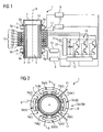
- Fig. 1 shows a section through a piston engine according to the invention 1.
- the piston engine 1 has a cylindrical housing 2, in which a cylindrical piston 3 is arranged to be movable. On the outer circumferential surface of the cylindrical piston 3, a magnetic yoke 4 is arranged. Outside the housing 2, on its cylindrical outer circumference, two magnetic circuits 7a to 7p for a magnetic mounting of the piston 3 are respectively arranged at four points 5a and 5b along the outer circumference at four bearing points 6a to 6d or 6e to 6g.
- An alternative embodiment not shown in the figures has three bearing points 6a to 6c, each with a magnetic circuit 7a to 7f, which may be sufficient for a stable mounting of the piston.
- the bearing points 6a to 6c and 6e to 6g are arranged along the outer circumference of the circular sectional area at equal distances from each other.
- the magnetic circuits 7a to 7p at the bearing points 6a to 6g may be constructed of permanent magnets or of electromagnetic coils. In the case of electromagnetic coils, these may each have a yoke.
- the magnetic circuits 7a to 7p generate magnetic fields which project into the housing 2 with magnetic field lines aligned perpendicular to the central axis 8. The interaction between these magnetic fields and the magnetic field, which is generated by the magnetic yoke 4 of the piston 3, leads to a non-contact, magnetic bearing of the piston 3 in the housing 2.
- the piston 3 is freely movable within the housing 2 along the central axis 8 ,
- the interaction of the magnetic fields of the yoke 4 and the magnetic circuits 7a to 7p keep the piston 3 in a floating state in the housing 2 without the piston 3 contacting the housing 2.
- the magnitude of the magnetic field of the magnetic circuits 7a to 7p of coils is determined electrically via a current flow within the coils.
- a control electronics of the magnetic circuits 9 controls or regulates the size of the currents in the coils and thus the size of the magnetic fields of the magnetic circuits 7a to 7p.
- distance sensors 11, which are arranged on the housing 2 provide information about the position of the piston 3 in the housing 2 and via an electronics of the distance sensors 12 and a central controller of the control electronics 10 signals to the control electronics of the magnetic circuits 7a to 7p.
- the signals are used to control the magnetic fields, and if the center axis of the piston deviates from the central axis of the housing 8, a distance sensor 11 can send a signal to the electronics 12, 10, 9, which results in an adaptation of the current in the magnetic circuits 7a to 7p. whereby the magnetic field changes and in interaction with the magnetic field of the yoke 4 of the piston 3, an additional force is exerted on the piston, which changes its position. The position is changed so that its central axis coincides with the central axis of the housing 8.
- coils 16a to 16e and a yoke 17 are disposed on the outer circumference of the housing 2, enclosing the coils 16a to 16e.
- the coils 16a to 16e in conjunction with the yoke 17 and in conjunction with the yoke 4 of the piston 3 form a linear machine 15th
- the yoke 4 of the piston 3 serves both the magnetic bearing of the piston 4, and as part of the linear machine 15.
- mechanical energy of the piston 4 can be converted directly into electrical energy and / or vice versa.
- Elaborate mechanism, which is subject to wear and should be lubricated, is saved.
- the linear machine 15 is connected via an electronic circuit 18 and an intermediate circuit 19 and an electronic system to the grid connection 20 to a power supply via terminals 21.
- a current which is generated by the linear machine 15 can be fed to an external power grid.
- Fig. 2 shows a cross section perpendicular to the longitudinal axis of the piston engine 1 at a point 5a or 5b.
- Two distance sensors 11 can be seen in the sectional view, which are mounted on the housing 2 and are integrated in the housing 2, and are arranged spatially slightly offset from the point 5a or 5b. As in Fig. 1 shown, at the second location 5b or 5a further two distance sensors 11 are arranged slightly spatially offset. About the four distance sensors 11, the position of the piston 3 relative to the housing 2 is uniquely determined.
- a first and a second chamber 13 and 14 are respectively formed along the longitudinal axis 8 at the beginning and end of the housing 2 and piston 3.
- the chambers 13 and 14 can serve as combustion chambers in an internal combustion engine, or in a sterling machine alternately a chamber can be heated and a chamber cooled and vice versa.
- a force is exerted on the piston 3, which generates the movement along the axis 8.
- the kinetic energy of the movement of the piston 3 can be converted directly into electrical energy by the linear machine 15.
- Fig. 2 On or integrated in the housing 2 are in Fig. 2 at the point 5a and 5b respectively four bearing points 6a to 6d and 6e to 6h shown. At each bearing point 6a to 6h two magnetic circuits 7 are arranged, each having a yoke or a common yoke, wherein for the sake of simplicity, only the latter in Fig. 2 is shown.
- Fig. 3 an alternative embodiment of the piston engine 1 according to the invention is shown.
- This embodiment leads compared to the embodiment in the Fig. 1 and 2 to a higher positional stability of the piston 3 relative to the housing 2 and prevents tilting of the piston 3 in the housing 2.
- the housing 2 as in Fig. 3 represented, arranged at the piston beginning and piston end in each case a hollow cylinder.
- the piston 3 is therefore each extended at its ends by means of a hollow cylindrical extension 22.
- Corresponding recesses 23 with a hollow cylindrical extensions 22 inverse shape are respectively formed at the housing beginning and housing end.
Landscapes
- Engineering & Computer Science (AREA)
- General Engineering & Computer Science (AREA)
- Mechanical Engineering (AREA)
- Chemical & Material Sciences (AREA)
- Combustion & Propulsion (AREA)
- Reciprocating, Oscillating Or Vibrating Motors (AREA)
- Magnetic Bearings And Hydrostatic Bearings (AREA)
- Bearings For Parts Moving Linearly (AREA)
- Compressors, Vaccum Pumps And Other Relevant Systems (AREA)
- Pistons, Piston Rings, And Cylinders (AREA)
Description
- Die vorliegende Erfindung bezieht sich auf eine Kolbenmaschine mit wenigstens einem ersten Kolben und wenigstens einem ersten Gehäuse. Das wenigstens eine erste Gehäuse umschließt den wenigstens einen ersten Kolben vollständig oder zumindest teilweise. Der wenigstens eine erste Kolben ist beweglich in dem wenigstens einen ersten Gehäuse magnetisch gelagert, mit Hilfe von wenigstens einer Einrichtung zur magnetischen Lagerung des wenigstens einen ersten Kolbens.
- Wärmekraftmaschinen werden zur Energieumwandlung von chemischer in mechanische Energie, von thermischer in mechanische Energie und von mechanischer in thermische Energie eingesetzt. Verbrennungskraftmaschinen als Wärmekraftmaschine wandeln chemische in mechanische Energie um, Stirlingmaschinen als Wärmekraftmaschine wandeln thermische in mechanische Energie um und wärmepumpen als Wärmekraftmaschine wandeln mechanische in thermische Energie um. Eine der am häufigsten eingesetzten Wärmekraftmaschinen ist die Kolbenmaschine, bei welcher mechanische Energie von einem Kolben auf eine Welle mit Hilfe von einem Pleuel übertragen wird.
- Ein alternativer Aufbau ist durch die Freikolbenmaschine gegeben. Eine Freikolbenmaschine ist eine Kolbenmaschine ohne Pleuel. Freikolbenmaschinen werden z.B. als Pumpe für ein hydraulisches System oder im zusammenspiel mit einem Lineargenerator zur direkten Erzeugung von elektrischer Energie eingesetzt.
- Unabhängig davon, ob eine Wärmekraftmaschine als klassische Kolbenmaschine oder als Freikolbenmaschine ausgebildet ist, tritt im Betrieb zwischen Kolben und Zylinder in der Regel Reibung auf, welcher zu Verschleiß führt. Der Verschleiß ergibt mit der Zeit eine eingeschränkte Funktion oder führt zu einer Zerstörung der Wärmekraftmaschine. Eine klassische Lösung des Problems der Reibung bzw. des Verschleißes erfolgt durch Schmierung der Maschine. Schmierung reduziert die mechanische Reibung zwischen Kolben und Zylinder, behebt das Problem des Verschleißes jedoch nicht vollständig. Insbesondere Querkräfte, welche auf den Kolben z.B. abhängig von der Position eines Pleuels wirken können, stellen eine mögliche Ursache für den Verschleiß des Kolben-Zylinder-Systems dar, welcher durch Schmierung nicht behoben wird. Eine Schmierung über eine Ölpumpe birgt weiterhin Probleme beim Anlassen der Maschine, wenn die Ölpumpe über die Kurbelwelle betrieben wird, und bei geringen Drehzahlen der Wärmekraftmaschine, bei welchen nur ein geringer Öldruck erzeugt wird.
- Verschleiß führt zu einer wesentlichen Verringerung der Lebensdauer von Maschinen. In Kraftfahrzeugen z.B. kann Verschleiß zu einer Verringerung der Lebensdauer auf 10000 Betriebsstunden und in Dieselmotoren von Baumaschinen kann Verschleiß zu einer Verringerung der Lebensdauer auf bis zu 15000 Betriebsstunden führen.
- Der Einsatz von Schmiermitteln führt ebenfalls zu Problemen. In Verbrennungskraftmaschinen wird immer ein Teil des Schmieröls mit verbrannt und führt so unter anderem zu einer erhöhten Umweltbelastung. Schmieröle werden durch Verunreinigungen und durch die auf sie ausgeübten Kräfte zerstört, weshalb bei geschmierten Maschinen ein hoher Wartungsaufwand durch regelmäßig notwendige Wechsel der Schmierstoffe anfällt.
- Aufgabe der erfindungsgemäßen Kolbenmaschine ist eine verschleißarme Funktion ohne den Einsatz von Schmierstoffen. Weitere Aufgabe der erfindungsgemäßen Kolbenmaschine ist ein einfacher Aufbau bei einer Verringerung von beweglichen, verschleißintensiven Teilen gegenüber üblichen Kolbenmaschinen. Eine Erhöhung der Lebensdauer der Maschine bei geringeren Herstellungskosten über eine Verringerung der Teilezahl ist eine weitere Aufgabe der erfindungsgemäßen Kolbenmaschine.
- Die angegebene Aufgabe wird bezüglich der Verbrennungsmaschine oder Sterlingmaschine mit den Merkmalen des Anspruchs 1 und bezüglich eines Verfahrens unter Verwendung der Verbrennungsmaschine oder Sterlingmaschine mit den Merkmalen des Anspruchs 15 gelöst.
- Vorteilhafte Ausgestaltungen der erfindungsgemäßen Verbrennungsmaschine oder Sterlingmaschine und des Verfahrens unter Verwendung der Verbrennungsmaschine oder Sterlingmaschine gehen aus den jeweils zugeordneten abhängigen Unteransprüchen hervor. Dabei können die Merkmale von Ansprüchen mit Merkmalen zugeordneter Unteransprüche kombiniert werden.
- Die erfindungsgemäße Verbrennungsmaschine oder Sterlingmaschine weist wenigstens einen ersten Kolben und wenigstens ein erstes Gehäuse auf, wobei das wenigstens eine erste Gehäuse den wenigstens einen ersten Kolben vollständig oder zumindest teilweise umschließt. Der wenigstens eine erste Kolben ist beweglich in dem wenigstens einen ersten Gehäuse magnetisch gelagert, mit Hilfe von wenigstens einer Einrichtung zur magnetischen Lagerung des wenigstens einen ersten Kolbens. Eine entsprechende Vorbrennungsmaschine ist aus
WO 02/40843 A US 4 889 039 A bekannt. Die wenigstens eine Einrichtungen zur magnetischen Lagerung des wenigstens einen ersten Kolbens ist relativ zu dem wenigstens einen ersten Gehäuse ortsfest angeordnet. Eine Größe eines Spaltes, welcher zwischen dem wenigstens einen ersten Kolben und dem wenigstens einem ersten Gehäuse besteht, ist durch eine Deformation des wenigstens einen ersten Kolben (3) und/oder durch Deformation des wenigstens einen ersten Gehäuses (2) einstellbar. Dabei sind insbesondere die Deformation oder die Deformationen durch die Wirkung eines Magnetfeldes hervorrufbar. - Durch die magnetische Lagerung des wenigstens einen ersten Kolbens in dem wenigstens einen ersten Gehäuse wird Reibung zwischen Kolben und Gehäuse verhindert und auf eine Verwendung von Schmiermitteln kann verzichtet werden. Eine ortsfeste Anordnung der wenigstens einen Einrichtung zur magnetischen Lagerung führt zu einem einfachen Aufbau mit einer minimalen Zahl an beweglichen Teilen. Eine solche Verbrennungsmaschine oder Sterlingmaschine ist einfach und kostengünstig herzustellen.
- Die wenigstens eine Einrichtungen zur magnetischen Lagerung des wenigstens einen ersten Kolbens kann wenigstens eine, relativ zu dem wenigstens einen ersten Gehäuse ortsfest angeordnete, elektromagnetische Spule aufweisen. Eine elektromagnetische Spule lässt sich einfach durch einen Strom steuern und das für die magnetische Lagerung des Kolbens notwendige Magnetfeld lässt sich einfach in seiner Größe einstellen. Alternativ kann eine magnetische Lagerung auch über Permanentmagnete erfolgen.
- Die wenigstens eine Einrichtung zur magnetischen Lagerung des wenigstens einen ersten Kolbens kann zwei Stellen zur Lagerung aufweisen mit jeweils drei Lagerpunkten. Durch diesen Aufbau können 4 Freiheitsgrade des Kolbens ausgeregelt werden und eine besonders stabile Lagerung erreicht werden. Die 4 Freiheitsgrade sind durch die Verschiebung des Kolbens in den zwei Achsen, welche senkrecht auf der Bewegungsachse des Kolbens liegen, und die Verkippung um diese zwei Achsen gegeben.
- Alternativ oder zusätzlich kann der wenigstens eine erste Kolben wenigstens eine magnetische Spule aufweisen. Dies ermöglicht über die Spule oder die Spulen des Kolbens eine Erzeugung und Steuerung des Magnetfeldes, welches der Lagerung des Kolbens dient.
- Der wenigstens eine erste Kolben kann wenigstens ein magnetisches Joch aufweisen, insbesondere ein geblechtes Joch und/oder ein Joch aus weichmagnetischen Kompositwerkstoffen. In dem Joch wird durch das Magnetfeld bei Bewegung des Kolbens ein Strom induziert, welcher ebenfalls ein Magnetfeld erzeugt. In Wechselwirkung mit dem Magnetfeld der wenigstens einen Einrichtung zur Lagerung des wenigstens einen ersten Kolbens wird der Kolben schwebend in dem wenigstens einen ersten Gehäuse gelagert. Auf eine Spule an oder in dem wenigstens einen ersten Kolben kann verzichtet werden, oder diese kann zusätzlich zur Feinsteuerung der Lagerung verwendet werden.
- Der wenigstens eine erste Kolben kann mit wenigstens einer Feder, insbesondere mit einem Federsystem mechanisch verbunden sein. Die Feder oder das Federsystem können die magnetische, reibungsfreie Lagerung des wenigstens einen ersten Kolbens unterstützen. Die Feder oder das Federsystem können auch zur Kraftübertragung vom Kolben auf andere Teile verwendet werden.
- Der wenigstens eine erste Kolben kann ein zylinderförmiger Rundkolben mit kreisrunder oder elyptischer Grundfläche sein und das wenigstens eine erste Gehäuse kann ein zylinderförmiges Gehäuse mit kreisrunder oder elyptischer Grundfläche sein. Dies führt zu einem besonders einfachen Aufbau. Eine elyptische Ausformung des Kolbens und des Gehäuses können eine stabile Lagerung auch über zwei Lagerstellen mit jeweils nur zwei Lagerpunkten ermöglichen oder bei drei Lagerpunkten zu einer Erhöhung der Lagerstabilität führen.
- Der wenigstens eine erste Kolben kann wenigstens eine Verlängerung aufweisen, welche die Form eines Hohlzylinders hat. Das wenigstens eine erste Gehäuse kann für die wenigstens eine Verlängerung eine Ausnehmung aufweisen. Über die Verlängerung und die entsprechende Ausnehmung im Gehäuse kann eine weitere Stabilisierung des Kolbens erreicht werden und ein Verkanten des Kolbens im Betrieb der Maschine verhindert werden.
- Die Verbrennungsmaschine oder Sterlingmaschine kann eine elektromagnetische Linearmaschine aufweisen. Durch die Kombination von magnetischer Lagerung des Kolbens und der elektromagnetischen Linearmaschine kann eine Energiewandlung direkt in der Linearmaschine erfolgen. Aufwendige mechanische Konstruktionen, welche unter Umständen geschmiert werden müssten, können so eingespart werden. Die elektromagnetische Linearmaschine und die wenigstens eine Einrichtungen zur magnetischen Lagerung des wenigstens einen ersten Kolbens können zwei voneinander getrennte Einrichtungen sein. Sie können aber auch gemeinsame Teile aufweisen. Im zweiten Fall können Teile, welche der magnetischen Lagerung dienen, bei der Energiewandlung durch die Linearmaschine verwendet werden. Dies führt zu einer Verringerung der Teilezahl gegenüber einem Aufbau mit getrennt voneinander aufgebauter Lagerung und Linearmaschine.
- Die elektromagnetische Linearmaschine kann Ringspulen aufweisen, welche entlang einer Bewegungsrichtung des wenigstens einen ersten Kolbens angeordnet sind. Dies führt zu einem besonders einfachen Aufbau und zu einer Energiewandlung durch die Linearmaschine mit einem hohen Wirkungsgrad.
- Die elektromagnetische Linearmaschine kann als Reluktanzmaschine, als PM-Synchronmaschine oder als Asynchronmaschine ausgeführt sein.
- Weiterhin kann die elektromagnetische Linearmaschine n-phasig, mit einer positiven, ganzen Zahl n, aufgebaut sein und/oder die Urwicklung der elektromagnetische Linearmaschine kann entlang einer Geraden m-fach, mit einer positiven, ganzen Zahl m, hintereinander wiederholt angeordnet sein.
- Zwischen dem wenigstens einen ersten Kolben und dem wenigstens einen ersten Gehäuse kann wenigstens eine erste Kammer gebildet sein, welche wenigstens einen Einström- und wenigstens einen Abströmkanal aufweist und/oder wenigstens ein Ventil aufweist. Dadurch wird durch die Verbrennungsmaschine oder Sterlingmaschine ein Kompressor oder eine Verbrennungsmaschine ausgebildet.
- Bei einem Verfahren unter Verwendung der zuvor beschriebenen Verbrennungsmaschine oder Sterlingmaschine erfolgt die Einstellung der Größe eines Spaltes, welcher zwischen dem wenigstens einen ersten Kolben und dem wenigstens einem ersten Gehäuse besteht, durch eine Deformation des wenigstens einen ersten Kolbens und/oder durch Deformation des wenigstens einen ersten Gehäuses. Insbesondere kann die Deformation oder die Deformationen durch die Wirkung eines Magnetfeldes hervorgerufen werden. Das Magnetfeld wiederum kann durch Einrichtungen erzeugt werden, welche gleichzeitig zur Lagerung und/oder für die Linearmaschine genutzt werden.
- Bei dem Verfahren kann eine Schlitzung des wenigstens einen ersten Gehäuses eine Verringerung der Kraft bewirken, welche zur Einstellung der Größe des Spaltes aufgewendet wird.
- Eine Dichtung kann in den Spalt eingebracht werden und die magnetische Lagerung des wenigstens einen ersten Kolbens kann eine genau definierte Druckkraft auf die Dichtung bewirken. Die Dichtung kann aus PCTFE oder Teflon bestehen.
- Das wenigstens eine erste Gehäuse kann auch gekühlt und/oder beheizt werden. Eine Kühlung und Beheizung kann gerade bei einer Ausführung der Verbrennungsmaschine oder Sterlingmaschine als Sterlingmotor vorteilhaft sein.
- Bevorzugte Ausführungsformen der Erfindung mit vorteilhaften Weiterbildungen gemäß den Merkmalen der abhängigen Ansprüche werden nachfolgend anhand der folgenden Figuren näher erläutert, ohne jedoch darauf beschränkt zu sein.
- Es zeigen:
- Fig. 1.
- einen Längsschnitt einer Kolbenmaschine mit magnetischer Lagerung sowie mit einer elektromagnetischen Linearmaschine, und
- Fig. 2
- einen Querschnitt senkrecht zu der Längsachse der in
Fig. 1 gezeigten Kolbenmaschine, und - Fig. 3
- einen Längsschnitt der Kolbenmaschine aus
Fig. 1 mit einer hohlzylinderförmigen Verlängerung des Kolbens und mit einer entsprechenden Ausnehmung im Gehäuse. -
Fig. 1 zeigt einen Schnitt durch eine erfindungsgemäße Kolbenmaschine 1. Die Kolbenmaschine 1 weist ein zylinderförmiges Gehäuse 2 auf, in welchem ein zylinderförmiger Kolben 3 beweglich angeordnet ist. Auf der äußeren Umfangsfläche des zylinderförmigen Kolbens 3 ist ein magnetisches Joch 4 angeordnet. Außerhalb des Gehäuses 2, an seinem zylinderförmigen Außenumfang, sind an zwei Stellen 5a und 5b entlang des Außenumfangs jeweils an vier Lagerpunkten 6a bis 6d oder 6e bis 6g jeweils zwei Magnetkreise 7a bis 7p für eine magnetische Lagerung des Kolbens 3 angeordnet. Eine nicht in den Figuren dargestellte alternative Ausführungsform weist drei Lagerpunkte 6a bis 6c mit jeweils einem Magnetkreis 7a bis 7f auf, was für eine stabile Lagerung des Kolbens ausreichend sein kann. Kombinationen der zuvor genannten Anzahl oder je nach Anwendung und Kraftwirkungen Änderungen in der Anzahl an Magnetkreisen, Lagerpunkten und Stellen sind entsprechend der gewünschten Anwendung möglich. In der Schnittdarstellung inFigur 1 sind der Einfachheit halber nur zwei Lagerpunkte 6a und 6c bzw. 6e und 6g je Stelle 5a und 5b dargestellt. Die Stellen der Magnetlagerung 5a und 5b sind entlang einer Mittelachse 8 des Gehäuses 2 jeweils in gleichem Abstand von einer Grund- und Deckfläche des zylinderförmigen Gehäuses 2 angeordnet. Entlang einer kreisrunden Schnittfläche durch das Gehäuse 2, senkrecht zur Mittelachse 8, jeweils an einer Stelle 5a oder 5b der Magnetlagerung, sind entlang des Außenumfangs der kreisrunden Schnittfläche, in gleichen Abständen voneinander, die Lagerpunkte 6a bis 6c bzw. 6e bis 6g angeordnet. - Die Magnetkreise 7a bis 7p an den Lagerpunkten 6a bis 6g können aus Permanentmagneten oder aus elektromagnetischen Spulen aufgebaut sein. Im Falle von elektromagnetischen Spulen können diese jeweils ein Joch aufweisen. Die Magnetkreise 7a bis 7p erzeugen Magnetfelder, welche mit senkrecht zur Mittelachse 8 ausgerichteten Magnetfeldlinien in das Gehäuse 2 hineinragen. Die Wechselwirkung zwischen diesen Magnetfeldern und dem Magnetfeld, welches durch das magnetische Joch 4 des Kolbens 3 erzeugt wird, führt zu einer berührungsfreien, magnetischen Lagerung des Kolbens 3 im Gehäuse 2. Dabei ist der Kolben 3 innerhalb des Gehäuses 2 entlang der Mittelachse 8 frei beweglich. Die Wechselwirkung der Magnetfelder des Jochs 4 und der Magnetkreise 7a bis 7p halten den Kolben 3 in einem Schwebezustand im Gehäuse 2, ohne dass der Kolben 3 das Gehäuse 2 berührt.
- wie in
Fig. 1 dargestellt, wird die Größe des Magnetfeldes der Magnetkreise 7a bis 7p aus Spulen jeweils elektrisch über einen Stromfluss innerhalb der Spulen bestimmt. Eine Steuerelektronik der Magnetkreise 9 steuert bzw. regelt die Größe der Ströme in den Spulen und damit die Größe der Magnetfelder der Magnetkreise 7a bis 7p. Bei einer Regelung können Abstandssensoren 11, welche am Gehäuse 2 angeordnet sind, Informationen über die Lage des Kolbens 3 im Gehäuse 2 liefern und über eine Elektronik der Abstandssensoren 12 und einem Zentralregler der Steuerelektronik 10 Signale an die Steuerelektronik der Magnetkreise 7a bis 7p geben. Über die Signale werden die Magnetfelder geregelt und bei Abweichung der Mittelachse des Kolbens von der Mittelachse des Gehäuses 8 kann ein Abstandssensor 11 ein Signal an die Elektronik 12, 10, 9 geben, was zu einer Anpassung des Stromes in den Magnetkreisen 7a bis 7p führt, wodurch das Magnetfeld sich ändert und in Wechselwirkung mit dem Magnetfeld des Jochs 4 des Kolbens 3 eine zusätzliche Kraft auf den Kolben ausgeübt wird, welche dessen Lage ändert. Die Lage wird so geändert, dass seine Mittelachse mit der Mittelachse des Gehäuses 8 übereinstimmt. - Wie in
Fig. 1 weiterhin dargestellt, sind auf dem Außenumfang des Gehäuses 2 Spulen 16a bis 16e sowie ein Joch 17 angeordnet, welches die Spulen 16a bis 16e umschließt. Die Spulen 16a bis 16e in Verbindung mit dem Joch 17 sowie in Verbindung mit dem Joch 4 des Kolbens 3 bilden eine Linearmaschine 15. Somit dient das Joch 4 des Kolbens 3 sowohl der magnetischen Lagerung des Kolbens 4, als auch als Teil der Linearmaschine 15. Mit Hilfe der Linearmaschine 15 kann mechanische Energie des Kolbens 4 direkt in elektrische Energie und/oder umgekehrt umgewandelt werden. Aufwendige Mechanik, welche dem Verschleiß unterliegt und geschmiert werden müsste, wird eingespart. Die Linearmaschine 15 ist über eine Elektronik 18 und einem Zwischenstromkreis 19 sowie einer Elektronik zur Netzanbindung 20 an ein Stromnetz über Anschlüsse 21 anschließbar. Somit ist ein Strom, welcher von der Linearmaschine 15 erzeugt wird einem äußeren Stromnetz zuführbar. -
Fig. 2 zeigt einen Querschnitt senkrecht zu der Längsachse der Kolbenmaschine 1 an einer Stelle 5a oder 5b. Zwei Abstandssensoren 11 sind in der Schnittdarstellung zu sehen, welche am Gehäuse 2 angebracht sind bzw. im Gehäuse 2 integriert sind, und räumlich leicht versetzt von der Stelle 5a oder 5b angeordnet sind. Wie inFig. 1 dargestellt, sind an der zweiten Stelle 5b oder 5a weitere zwei Abstandssensoren 11 leicht räumlich versetzt angeordnet. Über die vier Abstandssensoren 11 ist die Lage des Kolbens 3 relativ zum Gehäuse 2 eindeutig bestimmbar. - Zwischen Kolben 3 und Gehäuse 2 sind jeweils entlang der Längsachse 8 am Anfang und Ende des Gehäuses 2 und Kolbens 3 eine erste und eine zweite Kammer 13 und 14 ausgebildet. Bei der Bewegung des Kolbens 3 entlang der Längsachse 8 ändert sich das Volumen der Kammern 13 und 14. Nimmt das Volumen der Kammer 13 ab, so nimmt das Volumen der Kammer 14 zu und umgekehrt. Die Kammern 13 und 14 können als Verbrennungskammern in einer Verbrennungsmaschine dienen, oder in einer Sterlingmaschine kann abwechselnd eine Kammer erwärmt und eine Kammer abgekühlt werden sowie umgekehrt. Dadurch wird auf den Kolben 3 eine Kraft ausgeübt, welche die Bewegung längs der Achse 8 erzeugt. Die Bewegungsenergie der Bewegung des Kolbens 3 kann durch die Linearmaschine 15 direkt in elektrische Energie umgewandelt werden.
- Am bzw. integriert im Gehäuse 2 sind in
Fig. 2 an der Stelle 5a bzw. 5b jeweils vier Lagerpunkte 6a bis 6d bzw. 6e bis 6h gezeigt. An jedem Lagerpunkt 6a bis 6h sind jeweils zwei Magnetkreise 7 angeordnet, welche jeweils ein Joch oder ein gemeinsames Joch aufweisen, wobei der Einfachheit halber nur letzteres inFig. 2 dargestellt ist. - In
Fig. 3 ist eine alternative Ausführungsform der erfindungsgemäßen Kolbenmaschine 1 dargestellt. Diese Ausführungsform führt im Vergleich zu der Ausführungsform in denFig. 1 und 2 zu einer höheren Lagestabilität des Kolbens 3 relativ zum Gehäuse 2 bzw. verhindert ein Verkanten des Kolbens 3 im Gehäuse 2. Im Gehäuse 2 ist, wie inFig. 3 dargestellt, am Kolbenanfang und Kolbenende jeweils ein Hohlzylinder angeordnet. Der Kolben 3 ist also jeweils an seinen Enden mit Hilfe einer hohlzylinderförmigen Verlängerung 22 verlängert. Entsprechende Ausnehmungen 23 mit einer den hohlzylinderförmigen Verlängerungen 22 inversen Form sind jeweils am Gehäuseanfang und Gehäuseende ausgebildet.
Claims (18)
- Verbrennungsmaschine oder Sterlingmaschine (1) mit wenigstens einem ersten Kolben (3) und wenigstens einem ersten Gehäuse (2), wobei das wenigstens eine erste Gehäuse (2) den wenigstens einen ersten Kolben (3) vollständig oder zumindest teilweise umschließt, und der wenigstens eine erste Kolben (3) beweglich in dem wenigstens einen ersten Gehäuse (2) magnetisch gelagert ist, mit Hilfe von wenigstens einer Einrichtung (7) zur magnetischen Lagerung des wenigstens einen ersten Kolbens (3), dadurch gekennzeichnet, dass die wenigstens eine Einrichtungen (7) zur magnetischen Lagerung des wenigstens einen ersten Kolbens (3) relativ zu dem wenigstens einen ersten Gehäuse (2) ortsfest angeordnet ist und eine Größe eines Spaltes, welcher zwischen dem wenigstens einen ersten Kolben (3) und dem wenigstens einem ersten Gehäuse (2) besteht durch eine Deformation des wenigstens einen ersten Kolben (3) und/oder durch Deformation des wenigstens einen ersten Gehäuses (2) einstellbar ist, wobei insbesondere die Deformation oder die Deformationen durch die Wirkung eines Magnetfeldes hervorrufbar sind.
- Verbrennungsmaschine oder Sterlingmaschine (1) nach Anspruch 1, dadurch gekennzeichnet, dass die wenigstens eine Einrichtungen (7) zur magnetischen Lagerung des wenigstens einen ersten Kolbens wenigstens eine, relativ zu dem wenigstens einen ersten Gehäuse (2) ortsfest angeordnete, elektromagnetische Spule aufweist.
- Verbrennungsmaschine oder Sterlingmaschine (1) nach Anspruch 1 oder 2, dadurch gekennzeichnet, dass die wenigstens eine Einrichtung (7) zur magnetischen Lagerung des wenigstens einen ersten Kolbens (3) zwei Stellen (5a, 5b) zur Lagerung mit jeweils drei Lagerpunkten (6a bis 6f) aufweist.
- Verbrennungsmaschine oder Sterlingmaschine (1) nach einem der vorhergehenden Ansprüche, dadurch gekennzeichnet, dass der wenigstens eine erste Kolben (3) wenigstens eine magnetische Spule aufweist.
- Verbrennungsmaschine oder Sterlingmaschine (1) nach einem der vorhergehenden Ansprüche, dadurch gekennzeichnet, dass der wenigstens eine erste Kolben (3) wenigstens ein magnetisches Joch (4) aufweist, insbesondere ein geblechtes Joch (4) und/oder ein Joch (4) aus weichmagnetischen Kompositwerkstoffen.
- Verbrennungsmaschine oder Sterlingmaschine (1) nach einem der vorhergehenden Ansprüche, dadurch gekennzeichnet, dass der wenigstens eine erste Kolben (3) mit wenigstens einer Feder, insbesondere einem Federsystem mechanisch verbunden ist.
- Verbrennungsmaschine oder Sterlingmaschine (1) nach einem der vorhergehenden Ansprüche, dadurch gekennzeichnet, dass der wenigstens eine erste Kolben (3) ein zylinderförmiger Rundkolben mit kreisrunder oder elyptischer Grundfläche ist und das wenigstens eine erste Gehäuse (2) ein zylinderförmiges Gehäuse mit kreisrunder oder elyptischer Grundfläche ist.
- Verbrennungsmaschine oder Sterlingmaschine (1) nach einem der vorhergehenden Ansprüche, dadurch gekennzeichnet, dass der wenigstens eine erste Kolben (3) wenigstens eine Verlängerung (22) aufweist, welche die Form eines Hohlzylinders aufweist und dass das wenigstens eine erste Gehäuse (2) für die wenigstens eine Verlängerung (22) eine Ausnehmung (23) aufweist.
- Verbrennungsmaschine oder Sterlingmaschine (1) nach einem der vorhergehenden Ansprüche, dadurch gekennzeichnet, dass die Kolbenmaschine (1) eine elektromagnetische Linearmaschine (15) aufweist.
- Verbrennungsmaschine oder Sterlingmaschine (1) nach Anspruch 9, dadurch gekennzeichnet, dass die elektromagnetische Linearmaschine (15) Ringspulen (16a bis 16e) aufweist, welche entlang einer Bewegungsrichtung des wenigstens einen ersten Kolbens (3) angeordnet sind.
- Verbrennungsmaschine oder Sterlingmaschine (1) nach Anspruch 9 oder 10, dadurch gekennzeichnet, dass die elektromagnetische Linearmaschine (15) als Reluktanzmaschine oder als PM-Synchronmaschine oder als Asynchronmaschine ausgeführt ist.
- Verbrennungsmaschine oder Sterlingmaschine (1) nach einem der Ansprüche 9 bis 11, dadurch gekennzeichnet, dass die elektromagnetische Linearmaschine (15) n-phasig, mit einer positiven, ganzen Zahl n, aufgebaut ist und/oder die Urwicklung der elektromagnetische Linearmaschine entlang einer Geraden m-fach, mit einer positiven, ganzen Zahl m, hintereinander wiederholt angeordnet ist.
- Verbrennungsmaschine oder Sterlingmaschine (1) nach einem der Ansprüche 9 bis 12, dadurch gekennzeichnet, dass die elektromagnetische Linearmaschine (15) und die wenigstens eine Einrichtungen (7) zur magnetischen Lagerung des wenigstens einen ersten Kolbens (3) zwei voneinander getrennte Einrichtungen sind.
- Verbrennungsmaschine oder Sterlingmaschine (1) nach einem der vorhergehenden Ansprüche, dadurch gekennzeichnet, dass zwischen dem wenigstens
einen ersten Kolben (3) und dem wenigstens einen ersten Gehäuse (2) wenigstens eine erste Kammer (13) gebildet ist, welche wenigstens einen Einström- und wenigstens einen Abströmkanal aufweist und/oder wenigstens ein Ventil aufweist. - Verfahren unter Verwendung einer Verbrennungsmaschine oder Sterlingmaschine (1) nach einem der vorhergehenden Ansprüche, dadurch gekennzeichnet, dass die Einstellung der Größe eines Spaltes, welcher zwischen dem wenigstens einen ersten Kolben (3) und dem wenigstens einem ersten Gehäuse (2) besteht, durch eine Deformation des wenigstens einen ersten Kolben (3) und/oder durch Deformation des wenigstens einen ersten Gehäuses (2) erfolgt, wobei insbesondere die Deformation oder die Deformationen durch die Wirkung eines Magnetfeldes hervorgerufen werden.
- Verfahren nach Anspruch 15, dadurch gekennzeichnet, dass eine Schlitzung des wenigstens einen ersten Gehäuses (2) eine Verringerung der Kraft bewirkt, welche zur Einstellung der Größe des Spaltes aufgewendet wird.
- Verfahren nach Anspruch 15 oder 16, dadurch gekennzeichnet, dass eine Dichtung, insbesondere eine Dichtung bestehend aus PCTFE oder Teflon, in den Spalt eingebracht wird und dass die magnetische Lagerung des wenigstens einen ersten Kolbens (3) eine genau definierte Druckkraft auf die Dichtung bewirkt.
- Verfahren nach einem der Ansprüche 15 bis 17, dadurch gekennzeichnet, dass das wenigstens eine erste Gehäuse (2) gekühlt und/oder beheizt wird.
Applications Claiming Priority (2)
| Application Number | Priority Date | Filing Date | Title |
|---|---|---|---|
| DE102009040051.6A DE102009040051B4 (de) | 2009-09-03 | 2009-09-03 | Freikolbenmaschine mit magnetischer Lagerung des Kolbens |
| PCT/EP2010/062438 WO2011026774A1 (de) | 2009-09-03 | 2010-08-26 | Kolbenmaschine mit magnetischer lagerung des kolbens |
Publications (2)
| Publication Number | Publication Date |
|---|---|
| EP2473725A1 EP2473725A1 (de) | 2012-07-11 |
| EP2473725B1 true EP2473725B1 (de) | 2015-08-12 |
Family
ID=42989474
Family Applications (1)
| Application Number | Title | Priority Date | Filing Date |
|---|---|---|---|
| EP10750088.6A Not-in-force EP2473725B1 (de) | 2009-09-03 | 2010-08-26 | Kolbenmaschine mit magnetischer lagerung des kolbens |
Country Status (10)
| Country | Link |
|---|---|
| US (1) | US8978595B2 (de) |
| EP (1) | EP2473725B1 (de) |
| JP (1) | JP5518196B2 (de) |
| KR (1) | KR101378694B1 (de) |
| CN (1) | CN102482994B (de) |
| BR (1) | BR112012004963A2 (de) |
| CA (1) | CA2772845C (de) |
| DE (1) | DE102009040051B4 (de) |
| RU (1) | RU2502882C2 (de) |
| WO (1) | WO2011026774A1 (de) |
Cited By (1)
| Publication number | Priority date | Publication date | Assignee | Title |
|---|---|---|---|---|
| EP4078786A1 (de) * | 2019-12-16 | 2022-10-26 | Libertine FPE Ltd | Kraftkupplung für freikolbenmaschine |
Families Citing this family (16)
| Publication number | Priority date | Publication date | Assignee | Title |
|---|---|---|---|---|
| DE102009040051B4 (de) | 2009-09-03 | 2014-05-08 | Siemens Aktiengesellschaft | Freikolbenmaschine mit magnetischer Lagerung des Kolbens |
| GB2488850B (en) * | 2011-08-10 | 2013-12-11 | Libertine Fpe Ltd | Piston for a free piston engine generator |
| DE102013003341A1 (de) | 2013-02-27 | 2014-08-28 | Daimler Ag | Brennkraftmaschine für ein Kraftfahrzeug |
| CN103382902B (zh) * | 2013-07-17 | 2015-07-22 | 万斌 | 一种用于发电的集成式斯特林发动机 |
| US20150280628A1 (en) * | 2013-11-08 | 2015-10-01 | Joseph Sajan Jacob | Digital power plant |
| US11008864B2 (en) | 2014-04-24 | 2021-05-18 | Aquarius Engines (A.M.) Ltd. | Engine with work stroke and gas exchange through piston rod |
| US11346219B2 (en) | 2014-04-24 | 2022-05-31 | Aquarius Engines (A.M.) Ltd. | Engine with work stroke and gas exchange through piston rod |
| DK3322884T3 (da) | 2015-07-15 | 2021-03-29 | Aquarius Engines A M Ltd | Fri stempel-motor |
| WO2017068427A1 (en) | 2015-10-20 | 2017-04-27 | Shaul Yaakoby | Vibration prevention in a linear actuator |
| CN106704366B (zh) * | 2016-12-08 | 2019-02-15 | 广东工业大学 | 一种基于自适应调整动平衡的电磁主轴 |
| DE102018117732A1 (de) | 2017-07-31 | 2019-01-31 | Volkswagen Aktiengesellschaft | Zweitaktfreikolbenmotor |
| US10641166B1 (en) | 2018-12-03 | 2020-05-05 | Aquarius Engines (A.M.) Ltd. | Piston rod and free piston engine |
| US11008959B2 (en) * | 2019-06-28 | 2021-05-18 | Aquarius Engines Central Europe Sp. z o.o. | System and method for controlling engine using reference point |
| DE102020127897A1 (de) | 2020-10-22 | 2022-04-28 | Klaus W. Scheibe | Freikolbengenerator zur Erzeugung einer elektrischen Energie durch Induktion |
| US12098780B2 (en) * | 2021-03-03 | 2024-09-24 | Vieletech Inc. | Apparatus and method for engine control |
| CN116220899B (zh) * | 2021-12-02 | 2025-12-23 | 南京理工大学 | 双活塞直流扫气式自由活塞内燃直线发电机及其工作方法 |
Family Cites Families (34)
| Publication number | Priority date | Publication date | Assignee | Title |
|---|---|---|---|---|
| US3095901A (en) * | 1962-03-16 | 1963-07-02 | Vincent H Larson | Rapid opening valve |
| US4339109A (en) * | 1979-04-04 | 1982-07-13 | Aisin Seiki Kabushiki Kaisha | Electromagnetically operated valve unit |
| US4387935A (en) | 1980-12-08 | 1983-06-14 | The United States Of America As Represented By The Administrator Of The National Aeronautics And Space Administration | Linear magnetic bearing |
| US4473259A (en) | 1980-12-24 | 1984-09-25 | The United States Of America As Represented By The Administrator Of The National Aeronautics And Space Administration | Linear magnetic bearings |
| CH664193A5 (de) * | 1982-03-03 | 1988-02-15 | Wankel Felix | Abgasbetriebener rotationskolbenlader. |
| DE3378341D1 (en) * | 1982-06-30 | 1988-12-01 | Philips Nv | Magnetically suspended linear motor |
| WO1985000926A1 (fr) | 1983-08-12 | 1985-02-28 | Mitsubishi Denki Kabushiki Kaisha | Lampe a arc a vapeur de mercure a basse pression et son procede de fabrication |
| JPH0614464B2 (ja) | 1983-08-12 | 1994-02-23 | 三菱電機株式会社 | 低圧水銀蒸気放電灯 |
| JPS6039753U (ja) * | 1983-08-29 | 1985-03-19 | 松下電器産業株式会社 | フリ−ピストン式熱機関 |
| JPS6073106A (ja) | 1983-09-30 | 1985-04-25 | Bridgestone Corp | 弾性収縮体の連結部駆動方法 |
| JPS60217318A (ja) * | 1984-04-13 | 1985-10-30 | Mitsubishi Electric Corp | 光軸合わせ装置 |
| US4889039A (en) * | 1988-10-17 | 1989-12-26 | Miller Bernard F | Gas compressor with labyrinth sealing and active magnetic bearings |
| US5216308A (en) * | 1989-05-25 | 1993-06-01 | Avcon-Advanced Controls Technology, Inc. | Magnetic bearing structure providing radial, axial and moment load bearing support for a rotatable shaft |
| JP2837895B2 (ja) * | 1989-11-15 | 1998-12-16 | 三國重工業株式会社 | 往復動式ガス圧縮機 |
| US5329768A (en) * | 1991-06-18 | 1994-07-19 | Gordon A. Wilkins, Trustee | Magnoelectric resonance engine |
| DE69206229T2 (de) * | 1991-08-26 | 1996-03-28 | Toshiba Kawasaki Kk | Vorrichtung zum Tragen und zur linearen Bewegung eines Objektes. |
| US5514924A (en) * | 1992-04-30 | 1996-05-07 | AVCON--Advanced Control Technology, Inc. | Magnetic bearing providing radial and axial load support for a shaft |
| US5315197A (en) * | 1992-04-30 | 1994-05-24 | Avcon - Advance Controls Technology, Inc. | Electromagnetic thrust bearing using passive and active magnets, for coupling a rotatable member to a stationary member |
| US5250865A (en) * | 1992-04-30 | 1993-10-05 | Avcon - Advanced Controls Technology, Inc. | Electromagnetic thrust bearing for coupling a rotatable member to a stationary member |
| JP3778931B2 (ja) | 1994-06-09 | 2006-05-24 | リガッツィ、ピエール、アンドレア | リニア発電機 |
| RU2141570C1 (ru) * | 1994-06-09 | 1999-11-20 | Андреа Ригацци Пьер | Линейный генератор электроэнергии |
| US6035637A (en) * | 1997-07-01 | 2000-03-14 | Sunpower, Inc. | Free-piston internal combustion engine |
| RU2156870C2 (ru) * | 1998-12-18 | 2000-09-27 | Ермаков Алексей Иванович | Инерционные двигатель комбинированный, электродвигатель и преобразователь |
| RU2150014C1 (ru) | 1999-03-16 | 2000-05-27 | Пинский Феликс Ильич | Свободнопоршневой двигатель внутреннего сгорания с линейным электрическим генератором переменного тока |
| DE19922423A1 (de) * | 1999-05-14 | 2000-11-30 | Siemens Ag | Elektromechanischer Stellantrieb |
| RU2174734C1 (ru) * | 2000-03-30 | 2001-10-10 | Давыдов Радий Викторович | Электрическая машина возвратно-поступательного движения |
| FI108567B (fi) | 2000-11-20 | 2002-02-15 | Jaakko Larjola | Kaksitahtinen moottori |
| FR2819555B1 (fr) * | 2001-01-17 | 2003-05-30 | Conservatoire Nat Arts | Groupe electrogene a mouvement lineaire alternatif a base de moteur stirling, et procede mis en oeuvre dans ce groupe electrogene |
| SE0202336D0 (sv) * | 2002-07-30 | 2002-07-30 | Siemens Elema Ab | Valve assembly |
| CN1746496A (zh) * | 2004-09-06 | 2006-03-15 | 招慧霞 | 磁悬浮泵 |
| JP4595835B2 (ja) * | 2006-03-07 | 2010-12-08 | 株式会社日立製作所 | 鉛フリーはんだを用いたリード付き電子部品 |
| JP5309146B2 (ja) | 2007-10-04 | 2013-10-09 | シーレイト リミテッド ライアビリティー カンパニー | 電磁エンジン |
| US20100282187A1 (en) * | 2009-05-06 | 2010-11-11 | Briggs & Stratton Corporation | Engine with top-mounted tool |
| DE102009040051B4 (de) | 2009-09-03 | 2014-05-08 | Siemens Aktiengesellschaft | Freikolbenmaschine mit magnetischer Lagerung des Kolbens |
-
2009
- 2009-09-03 DE DE102009040051.6A patent/DE102009040051B4/de not_active Expired - Fee Related
-
2010
- 2010-08-26 KR KR1020127005646A patent/KR101378694B1/ko not_active Expired - Fee Related
- 2010-08-26 RU RU2012112815/06A patent/RU2502882C2/ru not_active IP Right Cessation
- 2010-08-26 CA CA2772845A patent/CA2772845C/en not_active Expired - Fee Related
- 2010-08-26 JP JP2012527284A patent/JP5518196B2/ja not_active Expired - Fee Related
- 2010-08-26 EP EP10750088.6A patent/EP2473725B1/de not_active Not-in-force
- 2010-08-26 US US13/394,254 patent/US8978595B2/en not_active Expired - Fee Related
- 2010-08-26 BR BR112012004963A patent/BR112012004963A2/pt not_active IP Right Cessation
- 2010-08-26 CN CN201080039291.5A patent/CN102482994B/zh not_active Expired - Fee Related
- 2010-08-26 WO PCT/EP2010/062438 patent/WO2011026774A1/de not_active Ceased
Cited By (3)
| Publication number | Priority date | Publication date | Assignee | Title |
|---|---|---|---|---|
| EP4078786A1 (de) * | 2019-12-16 | 2022-10-26 | Libertine FPE Ltd | Kraftkupplung für freikolbenmaschine |
| US12368360B2 (en) | 2019-12-16 | 2025-07-22 | Libertine Fpe Ltd | Power coupling for free piston mover |
| EP4078786B1 (de) * | 2019-12-16 | 2026-01-28 | Libertine FPE Ltd | Kraftkupplung für freikolbenmaschine |
Also Published As
| Publication number | Publication date |
|---|---|
| JP5518196B2 (ja) | 2014-06-11 |
| CA2772845A1 (en) | 2011-03-10 |
| EP2473725A1 (de) | 2012-07-11 |
| JP2013504002A (ja) | 2013-02-04 |
| US8978595B2 (en) | 2015-03-17 |
| RU2012112815A (ru) | 2013-10-10 |
| KR101378694B1 (ko) | 2014-03-27 |
| DE102009040051B4 (de) | 2014-05-08 |
| RU2502882C2 (ru) | 2013-12-27 |
| CN102482994A (zh) | 2012-05-30 |
| DE102009040051A1 (de) | 2011-03-10 |
| CA2772845C (en) | 2014-06-17 |
| WO2011026774A1 (de) | 2011-03-10 |
| CN102482994B (zh) | 2014-07-09 |
| US20120160190A1 (en) | 2012-06-28 |
| BR112012004963A2 (pt) | 2016-04-05 |
| KR20120054029A (ko) | 2012-05-29 |
Similar Documents
| Publication | Publication Date | Title |
|---|---|---|
| DE102009040051B4 (de) | Freikolbenmaschine mit magnetischer Lagerung des Kolbens | |
| DE102008041180B4 (de) | Stirling-Kreislaufmaschine | |
| DE60310191T2 (de) | Linearmotor und diesen verwendender linear-kompressor | |
| DE102014220470B4 (de) | Fahrpedal mit haptischer Signalgebung | |
| DE112010003623T5 (de) | Lagerstützsystem für freikolben-stirling maschinen | |
| EP1108283A1 (de) | Elektromagnetischer aktuator mit schwingendem feder-masse-system | |
| DE69830916T2 (de) | Elektromagnetische vorrichtung zur erzeugung einer linearen bewegung | |
| WO2013149758A2 (de) | Aktor zur dämpfung niederfrequenter schwingungen | |
| WO2003061099A2 (de) | Verbrennungsmotor mit in einem kurbelgehäuse gelagerter kurbelwelle, wobei der starter/generator auf der kurbelwelle angeordnet ist | |
| EP3364532A1 (de) | Linearaktuator | |
| WO2007085229A1 (de) | Strahltriebwerk mit aktivmagnetischer lagerung | |
| DE202023106333U1 (de) | Elektrische Maschine mit axial verschiebbarem Rotor | |
| DE4315463C1 (de) | Im Kurbeltrieb eines Hubkolbenmotors integriertes Stromerzeugungsaggregat | |
| WO2007107218A1 (de) | Segmentantrieb für ventiltrieb | |
| DE19723923A1 (de) | Ventilanordnung für einen ventilgesteuerten Verbrennungsmotor | |
| WO2021102496A1 (de) | Lageranordnung | |
| DE102008003135B4 (de) | Antriebseinheit für eine Haarschneidemaschine | |
| EP3161294B1 (de) | Nockenwellenversteller und verfahren zur bestimmung der einstellung eines nockenwellenverstellers | |
| EP3454349B1 (de) | Verfahren zur herstellung eines magnetanker-stössel-verbundes und magnetanker-stössel-verbund für einen linearaktuator | |
| DE102016213483A1 (de) | Vorrichtung zum Ausgleich freier Massenkräfte einer Hubkolbenbrennkraftmaschine | |
| DE3922986A1 (de) | Verbrennungsmotor mit lineargenerator | |
| DE10044789C2 (de) | Antiebsvorrichtung eines Gaswechselventils für einen ventilgesteuerten Verbrennungsmotor | |
| EP1869756B1 (de) | Linearaktor | |
| DE102005017482B4 (de) | Gaswechselventilaktor für einen ventilgesteuerten Verbrennungsmotor | |
| DE20305046U1 (de) | Kurbelwellengenerator |
Legal Events
| Date | Code | Title | Description |
|---|---|---|---|
| PUAI | Public reference made under article 153(3) epc to a published international application that has entered the european phase |
Free format text: ORIGINAL CODE: 0009012 |
|
| 17P | Request for examination filed |
Effective date: 20120227 |
|
| AK | Designated contracting states |
Kind code of ref document: A1 Designated state(s): AL AT BE BG CH CY CZ DE DK EE ES FI FR GB GR HR HU IE IS IT LI LT LU LV MC MK MT NL NO PL PT RO SE SI SK SM TR |
|
| DAX | Request for extension of the european patent (deleted) | ||
| RAP1 | Party data changed (applicant data changed or rights of an application transferred) |
Owner name: SIEMENS AKTIENGESELLSCHAFT |
|
| GRAP | Despatch of communication of intention to grant a patent |
Free format text: ORIGINAL CODE: EPIDOSNIGR1 |
|
| INTG | Intention to grant announced |
Effective date: 20141105 |
|
| GRAP | Despatch of communication of intention to grant a patent |
Free format text: ORIGINAL CODE: EPIDOSNIGR1 |
|
| INTG | Intention to grant announced |
Effective date: 20150320 |
|
| GRAS | Grant fee paid |
Free format text: ORIGINAL CODE: EPIDOSNIGR3 |
|
| GRAA | (expected) grant |
Free format text: ORIGINAL CODE: 0009210 |
|
| AK | Designated contracting states |
Kind code of ref document: B1 Designated state(s): AL AT BE BG CH CY CZ DE DK EE ES FI FR GB GR HR HU IE IS IT LI LT LU LV MC MK MT NL NO PL PT RO SE SI SK SM TR |
|
| REG | Reference to a national code |
Ref country code: GB Ref legal event code: FG4D Free format text: NOT ENGLISH |
|
| REG | Reference to a national code |
Ref country code: CH Ref legal event code: EP |
|
| REG | Reference to a national code |
Ref country code: AT Ref legal event code: REF Ref document number: 742368 Country of ref document: AT Kind code of ref document: T Effective date: 20150815 |
|
| REG | Reference to a national code |
Ref country code: FR Ref legal event code: PLFP Year of fee payment: 6 |
|
| REG | Reference to a national code |
Ref country code: IE Ref legal event code: FG4D Free format text: LANGUAGE OF EP DOCUMENT: GERMAN |
|
| REG | Reference to a national code |
Ref country code: DE Ref legal event code: R096 Ref document number: 502010010062 Country of ref document: DE |
|
| PGFP | Annual fee paid to national office [announced via postgrant information from national office to epo] |
Ref country code: GB Payment date: 20150812 Year of fee payment: 6 |
|
| PGFP | Annual fee paid to national office [announced via postgrant information from national office to epo] |
Ref country code: FR Payment date: 20150818 Year of fee payment: 6 |
|
| REG | Reference to a national code |
Ref country code: LT Ref legal event code: MG4D |
|
| REG | Reference to a national code |
Ref country code: NL Ref legal event code: MP Effective date: 20150812 |
|
| PG25 | Lapsed in a contracting state [announced via postgrant information from national office to epo] |
Ref country code: GR Free format text: LAPSE BECAUSE OF FAILURE TO SUBMIT A TRANSLATION OF THE DESCRIPTION OR TO PAY THE FEE WITHIN THE PRESCRIBED TIME-LIMIT Effective date: 20151113 Ref country code: FI Free format text: LAPSE BECAUSE OF FAILURE TO SUBMIT A TRANSLATION OF THE DESCRIPTION OR TO PAY THE FEE WITHIN THE PRESCRIBED TIME-LIMIT Effective date: 20150812 Ref country code: LT Free format text: LAPSE BECAUSE OF FAILURE TO SUBMIT A TRANSLATION OF THE DESCRIPTION OR TO PAY THE FEE WITHIN THE PRESCRIBED TIME-LIMIT Effective date: 20150812 Ref country code: LV Free format text: LAPSE BECAUSE OF FAILURE TO SUBMIT A TRANSLATION OF THE DESCRIPTION OR TO PAY THE FEE WITHIN THE PRESCRIBED TIME-LIMIT Effective date: 20150812 Ref country code: NO Free format text: LAPSE BECAUSE OF FAILURE TO SUBMIT A TRANSLATION OF THE DESCRIPTION OR TO PAY THE FEE WITHIN THE PRESCRIBED TIME-LIMIT Effective date: 20151112 |
|
| PGFP | Annual fee paid to national office [announced via postgrant information from national office to epo] |
Ref country code: IT Payment date: 20150929 Year of fee payment: 6 Ref country code: DE Payment date: 20151016 Year of fee payment: 6 |
|
| PG25 | Lapsed in a contracting state [announced via postgrant information from national office to epo] |
Ref country code: HR Free format text: LAPSE BECAUSE OF FAILURE TO SUBMIT A TRANSLATION OF THE DESCRIPTION OR TO PAY THE FEE WITHIN THE PRESCRIBED TIME-LIMIT Effective date: 20150812 Ref country code: IS Free format text: LAPSE BECAUSE OF FAILURE TO SUBMIT A TRANSLATION OF THE DESCRIPTION OR TO PAY THE FEE WITHIN THE PRESCRIBED TIME-LIMIT Effective date: 20151212 Ref country code: SE Free format text: LAPSE BECAUSE OF FAILURE TO SUBMIT A TRANSLATION OF THE DESCRIPTION OR TO PAY THE FEE WITHIN THE PRESCRIBED TIME-LIMIT Effective date: 20150812 Ref country code: ES Free format text: LAPSE BECAUSE OF FAILURE TO SUBMIT A TRANSLATION OF THE DESCRIPTION OR TO PAY THE FEE WITHIN THE PRESCRIBED TIME-LIMIT Effective date: 20150812 Ref country code: PL Free format text: LAPSE BECAUSE OF FAILURE TO SUBMIT A TRANSLATION OF THE DESCRIPTION OR TO PAY THE FEE WITHIN THE PRESCRIBED TIME-LIMIT Effective date: 20150812 Ref country code: PT Free format text: LAPSE BECAUSE OF FAILURE TO SUBMIT A TRANSLATION OF THE DESCRIPTION OR TO PAY THE FEE WITHIN THE PRESCRIBED TIME-LIMIT Effective date: 20151214 |
|
| PG25 | Lapsed in a contracting state [announced via postgrant information from national office to epo] |
Ref country code: NL Free format text: LAPSE BECAUSE OF FAILURE TO SUBMIT A TRANSLATION OF THE DESCRIPTION OR TO PAY THE FEE WITHIN THE PRESCRIBED TIME-LIMIT Effective date: 20150812 |
|
| REG | Reference to a national code |
Ref country code: CH Ref legal event code: PL |
|
| PG25 | Lapsed in a contracting state [announced via postgrant information from national office to epo] |
Ref country code: EE Free format text: LAPSE BECAUSE OF FAILURE TO SUBMIT A TRANSLATION OF THE DESCRIPTION OR TO PAY THE FEE WITHIN THE PRESCRIBED TIME-LIMIT Effective date: 20150812 Ref country code: CZ Free format text: LAPSE BECAUSE OF FAILURE TO SUBMIT A TRANSLATION OF THE DESCRIPTION OR TO PAY THE FEE WITHIN THE PRESCRIBED TIME-LIMIT Effective date: 20150812 Ref country code: LI Free format text: LAPSE BECAUSE OF NON-PAYMENT OF DUE FEES Effective date: 20150831 Ref country code: DK Free format text: LAPSE BECAUSE OF FAILURE TO SUBMIT A TRANSLATION OF THE DESCRIPTION OR TO PAY THE FEE WITHIN THE PRESCRIBED TIME-LIMIT Effective date: 20150812 Ref country code: SK Free format text: LAPSE BECAUSE OF FAILURE TO SUBMIT A TRANSLATION OF THE DESCRIPTION OR TO PAY THE FEE WITHIN THE PRESCRIBED TIME-LIMIT Effective date: 20150812 Ref country code: CH Free format text: LAPSE BECAUSE OF NON-PAYMENT OF DUE FEES Effective date: 20150831 |
|
| REG | Reference to a national code |
Ref country code: DE Ref legal event code: R097 Ref document number: 502010010062 Country of ref document: DE |
|
| PG25 | Lapsed in a contracting state [announced via postgrant information from national office to epo] |
Ref country code: MC Free format text: LAPSE BECAUSE OF FAILURE TO SUBMIT A TRANSLATION OF THE DESCRIPTION OR TO PAY THE FEE WITHIN THE PRESCRIBED TIME-LIMIT Effective date: 20150812 Ref country code: RO Free format text: LAPSE BECAUSE OF FAILURE TO SUBMIT A TRANSLATION OF THE DESCRIPTION OR TO PAY THE FEE WITHIN THE PRESCRIBED TIME-LIMIT Effective date: 20150812 |
|
| REG | Reference to a national code |
Ref country code: IE Ref legal event code: MM4A |
|
| PLBE | No opposition filed within time limit |
Free format text: ORIGINAL CODE: 0009261 |
|
| STAA | Information on the status of an ep patent application or granted ep patent |
Free format text: STATUS: NO OPPOSITION FILED WITHIN TIME LIMIT |
|
| 26N | No opposition filed |
Effective date: 20160513 |
|
| PG25 | Lapsed in a contracting state [announced via postgrant information from national office to epo] |
Ref country code: IE Free format text: LAPSE BECAUSE OF NON-PAYMENT OF DUE FEES Effective date: 20150826 |
|
| PG25 | Lapsed in a contracting state [announced via postgrant information from national office to epo] |
Ref country code: SI Free format text: LAPSE BECAUSE OF FAILURE TO SUBMIT A TRANSLATION OF THE DESCRIPTION OR TO PAY THE FEE WITHIN THE PRESCRIBED TIME-LIMIT Effective date: 20150812 |
|
| REG | Reference to a national code |
Ref country code: AT Ref legal event code: MM01 Ref document number: 742368 Country of ref document: AT Kind code of ref document: T Effective date: 20150826 |
|
| PG25 | Lapsed in a contracting state [announced via postgrant information from national office to epo] |
Ref country code: AT Free format text: LAPSE BECAUSE OF NON-PAYMENT OF DUE FEES Effective date: 20150826 |
|
| REG | Reference to a national code |
Ref country code: DE Ref legal event code: R119 Ref document number: 502010010062 Country of ref document: DE |
|
| PG25 | Lapsed in a contracting state [announced via postgrant information from national office to epo] |
Ref country code: MT Free format text: LAPSE BECAUSE OF FAILURE TO SUBMIT A TRANSLATION OF THE DESCRIPTION OR TO PAY THE FEE WITHIN THE PRESCRIBED TIME-LIMIT Effective date: 20150812 |
|
| GBPC | Gb: european patent ceased through non-payment of renewal fee |
Effective date: 20160826 |
|
| REG | Reference to a national code |
Ref country code: FR Ref legal event code: ST Effective date: 20170428 |
|
| PG25 | Lapsed in a contracting state [announced via postgrant information from national office to epo] |
Ref country code: HU Free format text: LAPSE BECAUSE OF FAILURE TO SUBMIT A TRANSLATION OF THE DESCRIPTION OR TO PAY THE FEE WITHIN THE PRESCRIBED TIME-LIMIT; INVALID AB INITIO Effective date: 20100826 Ref country code: SM Free format text: LAPSE BECAUSE OF FAILURE TO SUBMIT A TRANSLATION OF THE DESCRIPTION OR TO PAY THE FEE WITHIN THE PRESCRIBED TIME-LIMIT Effective date: 20150812 Ref country code: BG Free format text: LAPSE BECAUSE OF FAILURE TO SUBMIT A TRANSLATION OF THE DESCRIPTION OR TO PAY THE FEE WITHIN THE PRESCRIBED TIME-LIMIT Effective date: 20150812 |
|
| PG25 | Lapsed in a contracting state [announced via postgrant information from national office to epo] |
Ref country code: CY Free format text: LAPSE BECAUSE OF FAILURE TO SUBMIT A TRANSLATION OF THE DESCRIPTION OR TO PAY THE FEE WITHIN THE PRESCRIBED TIME-LIMIT Effective date: 20150812 |
|
| PG25 | Lapsed in a contracting state [announced via postgrant information from national office to epo] |
Ref country code: GB Free format text: LAPSE BECAUSE OF NON-PAYMENT OF DUE FEES Effective date: 20160826 Ref country code: BE Free format text: LAPSE BECAUSE OF NON-PAYMENT OF DUE FEES Effective date: 20150831 Ref country code: DE Free format text: LAPSE BECAUSE OF NON-PAYMENT OF DUE FEES Effective date: 20170301 Ref country code: FR Free format text: LAPSE BECAUSE OF NON-PAYMENT OF DUE FEES Effective date: 20160831 |
|
| PG25 | Lapsed in a contracting state [announced via postgrant information from national office to epo] |
Ref country code: IT Free format text: LAPSE BECAUSE OF NON-PAYMENT OF DUE FEES Effective date: 20160826 Ref country code: TR Free format text: LAPSE BECAUSE OF FAILURE TO SUBMIT A TRANSLATION OF THE DESCRIPTION OR TO PAY THE FEE WITHIN THE PRESCRIBED TIME-LIMIT Effective date: 20150812 |
|
| PG25 | Lapsed in a contracting state [announced via postgrant information from national office to epo] |
Ref country code: LU Free format text: LAPSE BECAUSE OF NON-PAYMENT OF DUE FEES Effective date: 20150826 |
|
| PG25 | Lapsed in a contracting state [announced via postgrant information from national office to epo] |
Ref country code: MK Free format text: LAPSE BECAUSE OF FAILURE TO SUBMIT A TRANSLATION OF THE DESCRIPTION OR TO PAY THE FEE WITHIN THE PRESCRIBED TIME-LIMIT Effective date: 20150812 |
|
| PG25 | Lapsed in a contracting state [announced via postgrant information from national office to epo] |
Ref country code: AL Free format text: LAPSE BECAUSE OF FAILURE TO SUBMIT A TRANSLATION OF THE DESCRIPTION OR TO PAY THE FEE WITHIN THE PRESCRIBED TIME-LIMIT Effective date: 20150812 |