EP2472679B1 - Dispositif de brosse dans une installation de commutateur dans une machine électrique - Google Patents
Dispositif de brosse dans une installation de commutateur dans une machine électrique Download PDFInfo
- Publication number
- EP2472679B1 EP2472679B1 EP11194228.0A EP11194228A EP2472679B1 EP 2472679 B1 EP2472679 B1 EP 2472679B1 EP 11194228 A EP11194228 A EP 11194228A EP 2472679 B1 EP2472679 B1 EP 2472679B1
- Authority
- EP
- European Patent Office
- Prior art keywords
- brush
- holding part
- brush holder
- wall
- spring element
- Prior art date
- Legal status (The legal status is an assumption and is not a legal conclusion. Google has not performed a legal analysis and makes no representation as to the accuracy of the status listed.)
- Active
Links
Images


Classifications
-
- H—ELECTRICITY
- H01—ELECTRIC ELEMENTS
- H01R—ELECTRICALLY-CONDUCTIVE CONNECTIONS; STRUCTURAL ASSOCIATIONS OF A PLURALITY OF MUTUALLY-INSULATED ELECTRICAL CONNECTING ELEMENTS; COUPLING DEVICES; CURRENT COLLECTORS
- H01R39/00—Rotary current collectors, distributors or interrupters
- H01R39/02—Details for dynamo electric machines
- H01R39/38—Brush holders
- H01R39/381—Brush holders characterised by the application of pressure to brush
Definitions
- the invention relates to a brush arrangement in a commutator device in an electrical machine according to the preamble of claim 1.
- the brush assembly comprises a tubular brush holder with a carbon brush received therein, which is pressed by a spring element against the lateral surface of a collector, which rotates with the motor shaft of the electric machine.
- the spring element is secured to a cover part, which is placed on the outside of the brush holder and connected thereto.
- the carbon brush is used including spring element via a collector facing away from, frontal opening in the brush holder and fixed the lid member from the outside to the front side of the brush holder via mounting screws or locking elements.
- the invention has for its object to form a brush assembly, which is part of a commutator in an electric machine, easy to install with ease of installation measures.
- the brush arrangement according to the invention is part of a commutator device in an electrical machine, via which power is transmitted to an armature packet, which rotates with the motor shaft rotatably.
- the commutator comprises, in addition to the brush assembly and a collector which is connected to the motor shaft and on the lateral surface of a brush of the brush assembly, via which the power is transmitted, is applied.
- the brush assembly comprises a brush holder or a brush holder, in which or the brush - usually a carbon brush - is slidably mounted.
- the brush holder with the receiving area for the brush disposed therein is aligned radially to the motor shaft axis, so that the brush is pressed in the radial direction on the lateral surface of the circulating with the motor shaft collector.
- the brush is powered by a spring element in the direction of the collector.
- the spring element is attached to a holding part which is fixed in the mounted position on the brush holder.
- the brush holder is cup-shaped, wherein the holding part rests against the inner bottom of the brush holder and is fixed to a wall of the brush holder. The fixation can be done both on the bottom side and on the side walls in the interior of the brush holder.
- This embodiment has the advantage that the spring element and the holding part can be combined to form an assembly which is assembled before insertion into the interior of the cup-shaped brush holder, so that the holding part and the spring element are fixed to each other. Subsequently, the assembly, consisting of spring element and holding part, connected to the inner wall of the brush holder. Due to the fixation of the spring element on the holding part inadvertent falling out of the spring element is excluded from the brush holder during the assembly process. The assembly is thereby simplified as a whole. At the same time, the holding part and the spring element are securely received in the cup-shaped interior of the brush holder and protected from contamination from the outside. The assembly of the assembly takes place exclusively on the holding part, but not between the spring element and the brush holder. Holding part and spring element are, for example, snap-locked together.
- the attachment of the holding part on the inner wall of the brush holder can be done in various ways.
- the brush holder is designed as an injection-molded plastic component and the holding part is injected into the wall of the brush holder. Possible here is both an injection into the bottom of the brush holder and in the side walls.
- the holding part is positively or positively received on the wall of the brush holder.
- the frictional connection is achieved for example by at least one latching projection, which is arranged on the holding part and projects beyond the lateral surface of the holding part and is inserted into an associated recess in the wall of the brush holder.
- the frictional connection is achieved for example by friction between the latching projection on the holding part and the recess in the wall of the brush holder.
- latching elements are likewise advantageously provided on the holding part and on the wall of the brush holder, which, however, do not engage in force or frictional engagement, but additionally, if necessary, interengage exclusively via a positive connection.
- a latching hook or a latching lug on a latching projection which protrudes from the holding part, which is received in the mounted position with an undercut in an associated recess in the wall of the brush holder.
- the recess has for insertion of the latching projection advantageously a larger cross-section than the latching projection, so that the latching projection including the latching hook can be introduced until reaching the mounted position.
- the latching hook engages in the fully inserted position a wall portion on the brush holder, whereby the desired positive connection is achieved.
- the latching projection extends in the axial direction of the brush holder, which coincides with the direction of displacement of the brush at the same time.
- the latching projection extends in the direction of the bottom and projects into recesses which are introduced into the bottom of the brush holder. These recesses may extend completely through the floor.
- the latching projections are at an angle to the longitudinal axis of the brush holder and protrude into associated recesses. It can be arranged, for example, two or more locking projections, which are each arranged at an angle to the longitudinal axis of the brush holder, whereby also a positive connection is made.
- latching projections extend in the radial direction and protrude into recesses, which are also introduced in the radial direction in the wall of the brush holder.
- the holding part In the inserted state, the holding part is adjacent to the inner bottom of the brush holder.
- a direct contact of the holding part with the ground is possible, wherein also embodiments are contemplated in which the holding part has a distance from the ground.
- FIG. 1 an assembly 1 is shown, consisting of a helical spring element 2 and a holding part 3, which is part of a brush assembly in a commutator in an electrical machine.
- the holding part 3 is annular or disc-shaped and designed in particular as a sheet metal or metal part.
- the holding part 3 has integrally formed, clamp-shaped connecting elements 4, with which the holding part 3 is connected to the spring element 2.
- the holding part 3 is arranged at one end of the spring element 2. At the end face facing away from the spring element, the holding part 3 has integrally formed latching projections 5, which extend in the direction of the longitudinal axis of the spring element 2 and protrude axially beyond the end face of the holding part 3. About the locking projections 5 is a latching connection with a brush holder of the brush assembly.
- FIG. 2 to 4 are different views or sectional views of the brush assembly 6 with the brush holder 7 and the inserted assembly 1, consisting of spring element 2 and holding part 3, shown.
- the brush holder 7 is cup-shaped, wherein in the mounted state, the disk-shaped holding part 3 rests against the bottom of the inside of the brush holder 7.
- the latching projections 5, which are formed integrally with the holding part 3, project into associated latching recesses 8, which are introduced into the bottom of the brush holder 7 and project completely through the bottom.
- the latching projections 5 are received with latching or frictional engagement in the latching recesses 8 and thus secure the assembly 1 in the brush holder 7.
- the spring element 2 acts on its opposite side of the holding part 3, a carbon brush in the direction of a collector which rotatably rotates with the motor shaft of the electric machine.
- a carbon brush 10 is arranged on the holding part 3 opposite side of the spring element 2, which is pressed against the outer surface of a revolving with the motor shaft collector 11 for power transmission by the force of the spring element.
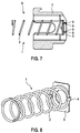
- a further embodiment is shown, which in the construction largely the one according to the Fig. 1 to 4 equivalent.
- the type of latching connection between the holding part 3 and the brush holder 7 is different.
- the latching projections 5 on the end face of the holding part 3, which point to the bottom of the brush arrangement 6 in the installed state and protrude into the axially aligned latching recesses 8 in the bottom, are adjacent to its free end face a latching hook or a detent 9, which, in particular Fig. 7 can be seen in the assembled state positively engages behind a paragraph at the bottom of the brush holder 7.
- a secure connection of the assembly 1 is given to the brush holder 7.
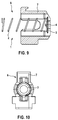
- FIG. 8 to 10 is a further embodiment of an assembly 1 with a spring element 2 and a holding part 3 and a brush assembly 6 is shown.
- the holding part 3 is formed without latching projections, the spring element 2 facing away from the end face of the holding part 3 is smooth-surfaced.
- the connection to the brush holder 7 is made by molding the holding part 3 with the material of the brush holder 7.
- the brush holder 7 is designed as an injection-molded plastic component. During the injection molding process, the holding part 3 is encapsulated by the material of the brush holder 7 at least in the region of its peripheral edge. In the finished state, the peripheral edge of the holding part 3 projects into the lateral inner walls of the brush holder 7.
Claims (12)
- Système de brosse dans un dispositif commutateur dans une machine électrique, comportant au moins une brosse (10) qui est guidée de manière coulissante dans un support de broche (7) et qui est sollicitée par un élément à ressort (2) maintenu dans une pièce de maintien (3) fixée au support de brosse (7), caractérisé en ce que la pièce de maintien (3) repose sur un fond intérieur en forme de coupelle du support de brosse (7) et est fixée à une paroi du support de brosse (7).
- Système de brosse selon la revendication 1, caractérisé en ce que le support de brosse (7) est réalisé sous la forme d'une pièce en matière plastique moulée par injection.
- Système de brosse selon la revendication 2, caractérisé en ce que la pièce de maintien (3) est injectée dans la paroi du support de brosse (7).
- Système de brosse selon l'une quelconque des revendications 1 à 3, caractérisé en ce que la pièce de maintien (3) est fixée sur le fond du support de brosse (7).
- Système de brosse selon l'une quelconque des revendications 1 à 4, caractérisé en ce que la pièce de maintien (3) est maintenue par complémentarité de forme sur la paroi du support de brosse (7).
- Système de brosse selon l'une quelconque des revendications 1 à 5, caractérisé en ce que la pièce de maintien (3) est maintenue par complémentarité de force sur la paroi du support de brosse (7).
- Système de brosse selon l'une quelconque des revendications 1 à 6, caractérisé en ce que la pièce de maintien (3) est maintenue par l'intermédiaire d'éléments d'encliquetage sur la paroi du support de brosse (7).
- Système de brosse selon la revendication 7, caractérisé en ce qu'au moins une protubérance d'encliquetage (5) est disposée sur la pièce de maintien (3), laquelle protubérance s'encliquète dans un évidement (8) associé dans la paroi du support de brosse (7).
- Système de brosse selon la revendication 8, caractérisé en ce que la protubérance d'encliquetage (5) présente un ergot d'encliquetage (9) qui, en position montée, est reçu en contre-dépouille dans l'évidement (8) ménagé dans la paroi du support de brosse (7).
- Système de brosse selon l'une quelconque des revendications 1 à 9, caractérisé en ce que l'élément à ressort (2) est relié par l'intermédiaire d'éléments de liaison (4) à la pièce de maintien (3), lesquels éléments de liaison sont réalisés d'un seul tenant avec la pièce de maintien (3).
- Dispositif commutateur dans une machine électrique comportant un système de brosse (6) selon l'une quelconque des revendications 1 à 10.
- Machine électrique comportant un dispositif commutateur selon la revendication 11.
Applications Claiming Priority (1)
| Application Number | Priority Date | Filing Date | Title |
|---|---|---|---|
| DE201010064234 DE102010064234A1 (de) | 2010-12-28 | 2010-12-28 | Bürstenanordnung in einer Kommutatoreinrichtung in einer elektrischen Maschine |
Publications (2)
| Publication Number | Publication Date |
|---|---|
| EP2472679A1 EP2472679A1 (fr) | 2012-07-04 |
| EP2472679B1 true EP2472679B1 (fr) | 2016-07-13 |
Family
ID=45566801
Family Applications (1)
| Application Number | Title | Priority Date | Filing Date |
|---|---|---|---|
| EP11194228.0A Active EP2472679B1 (fr) | 2010-12-28 | 2011-12-19 | Dispositif de brosse dans une installation de commutateur dans une machine électrique |
Country Status (5)
| Country | Link |
|---|---|
| EP (1) | EP2472679B1 (fr) |
| CN (1) | CN102570230B (fr) |
| DE (1) | DE102010064234A1 (fr) |
| HU (1) | HUE030214T2 (fr) |
| PL (1) | PL2472679T3 (fr) |
Families Citing this family (1)
| Publication number | Priority date | Publication date | Assignee | Title |
|---|---|---|---|---|
| CN106159625B (zh) * | 2016-08-10 | 2018-03-27 | 张宏伟 | 发电机碳刷组件的自动移动装置 |
Family Cites Families (7)
| Publication number | Priority date | Publication date | Assignee | Title |
|---|---|---|---|---|
| US2474601A (en) * | 1948-03-19 | 1949-06-28 | Gen Electric | Brush mechanism |
| JPH0448134Y2 (fr) * | 1987-05-29 | 1992-11-12 | ||
| US5872414A (en) * | 1995-02-07 | 1999-02-16 | Sawafuji Electric Co., Ltd | Electric rotating machine |
| CN1203592C (zh) * | 2001-12-10 | 2005-05-25 | 三菱电机株式会社 | 旋转电机用的电刷保持装置 |
| JP2005223974A (ja) | 2004-02-03 | 2005-08-18 | Nidec Shibaura Corp | 直流モータにおけるブラシの取付け構造 |
| JP2008125202A (ja) * | 2006-11-10 | 2008-05-29 | Hitachi Appliances Inc | 整流子電動機のブラシ装置及び電気掃除機 |
| US7402933B1 (en) * | 2007-08-16 | 2008-07-22 | Phoenix Electric Mfg. Co. | Constant force modular integrated internal brush holder |
-
2010
- 2010-12-28 DE DE201010064234 patent/DE102010064234A1/de not_active Withdrawn
-
2011
- 2011-12-19 HU HUE11194228A patent/HUE030214T2/hu unknown
- 2011-12-19 PL PL11194228T patent/PL2472679T3/pl unknown
- 2011-12-19 EP EP11194228.0A patent/EP2472679B1/fr active Active
- 2011-12-28 CN CN201110461375.4A patent/CN102570230B/zh active Active
Also Published As
| Publication number | Publication date |
|---|---|
| EP2472679A1 (fr) | 2012-07-04 |
| DE102010064234A1 (de) | 2012-06-28 |
| CN102570230B (zh) | 2016-05-18 |
| PL2472679T3 (pl) | 2017-01-31 |
| HUE030214T2 (hu) | 2017-04-28 |
| CN102570230A (zh) | 2012-07-11 |
Similar Documents
| Publication | Publication Date | Title |
|---|---|---|
| EP1851830B1 (fr) | Systeme de liaison, notamment systeme de connexion electrique | |
| DE3529208C2 (fr) | ||
| EP2146820B2 (fr) | Machine-outil, notamment machine-outil manuelle | |
| WO2010130520A1 (fr) | Machine-outil portative, notamment machine-outil électrique portative | |
| EP2435210B1 (fr) | Machine-outil, notamment machine-outil à main | |
| DE102015108831A1 (de) | Verriegelungssystem für einen Ladestecker | |
| EP2998485A1 (fr) | Bouton rotatif destine a actionner un adaptateur de cylindre d'un barillet | |
| DE102009026516A1 (de) | Werkzeugmaschine, insbesondere Handwerkzeugmaschine | |
| WO2013020571A1 (fr) | Mixeur plongeur | |
| DE60315799T2 (de) | Anschlussklemme für Elektromotor | |
| DE102008000732A1 (de) | Handwerkzeugmaschine, insbesondere handgeführte Schleifmaschine | |
| EP2472679B1 (fr) | Dispositif de brosse dans une installation de commutateur dans une machine électrique | |
| EP2745025B1 (fr) | Dispositif d'entraînement à transmission | |
| DE102009002969A1 (de) | Handwerkzeugmaschine, insbesondere Elektrohandwerkzeugmaschine | |
| WO2009115143A1 (fr) | Machine-outil à main, en particulier meuleuse à main | |
| EP2005556B1 (fr) | Element en matiere synthetique | |
| EP2268450B1 (fr) | Machine-outil à main, en particulier meuleuse à main | |
| WO2015154755A1 (fr) | Déphaseur d'arbre à cames avec coulisseau de verrouillage à complémentarité de formes | |
| WO2018007440A1 (fr) | Dispositif de fixation d'un moteur électrique et siège | |
| DE202006019194U1 (de) | Getriebeeinheit eines Verstellsystems und Gehäuse einer solchen Getriebeeinheit | |
| DE10035254B4 (de) | Verschlußelement für das Gehäuse des Motors eines Kraftfahrzeuganlassers und Anlasser mit einem solchen Verschlußelement | |
| EP3317950B1 (fr) | Système pour positionnement de prise | |
| DE202014007116U1 (de) | Elektrische Steckverbindungen | |
| DE102007039550A1 (de) | Elektromotor | |
| EP2795769B1 (fr) | Élément de sécurité anti-torsion en matière plastique pour câble électrique au niveau d'une pièce de raccordement électrique dans une machine électrique |
Legal Events
| Date | Code | Title | Description |
|---|---|---|---|
| AK | Designated contracting states |
Kind code of ref document: A1 Designated state(s): AL AT BE BG CH CY CZ DE DK EE ES FI FR GB GR HR HU IE IS IT LI LT LU LV MC MK MT NL NO PL PT RO RS SE SI SK SM TR |
|
| AX | Request for extension of the european patent |
Extension state: BA ME |
|
| PUAI | Public reference made under article 153(3) epc to a published international application that has entered the european phase |
Free format text: ORIGINAL CODE: 0009012 |
|
| 17P | Request for examination filed |
Effective date: 20130104 |
|
| GRAP | Despatch of communication of intention to grant a patent |
Free format text: ORIGINAL CODE: EPIDOSNIGR1 |
|
| INTG | Intention to grant announced |
Effective date: 20160315 |
|
| GRAS | Grant fee paid |
Free format text: ORIGINAL CODE: EPIDOSNIGR3 |
|
| GRAA | (expected) grant |
Free format text: ORIGINAL CODE: 0009210 |
|
| AK | Designated contracting states |
Kind code of ref document: B1 Designated state(s): AL AT BE BG CH CY CZ DE DK EE ES FI FR GB GR HR HU IE IS IT LI LT LU LV MC MK MT NL NO PL PT RO RS SE SI SK SM TR |
|
| REG | Reference to a national code |
Ref country code: GB Ref legal event code: FG4D Free format text: NOT ENGLISH |
|
| REG | Reference to a national code |
Ref country code: AT Ref legal event code: REF Ref document number: 812978 Country of ref document: AT Kind code of ref document: T Effective date: 20160715 Ref country code: CH Ref legal event code: EP |
|
| REG | Reference to a national code |
Ref country code: IE Ref legal event code: FG4D Free format text: LANGUAGE OF EP DOCUMENT: GERMAN |
|
| REG | Reference to a national code |
Ref country code: DE Ref legal event code: R096 Ref document number: 502011010150 Country of ref document: DE |
|
| REG | Reference to a national code |
Ref country code: LT Ref legal event code: MG4D |
|
| REG | Reference to a national code |
Ref country code: NL Ref legal event code: MP Effective date: 20160713 |
|
| REG | Reference to a national code |
Ref country code: FR Ref legal event code: PLFP Year of fee payment: 6 |
|
| PG25 | Lapsed in a contracting state [announced via postgrant information from national office to epo] |
Ref country code: HR Free format text: LAPSE BECAUSE OF FAILURE TO SUBMIT A TRANSLATION OF THE DESCRIPTION OR TO PAY THE FEE WITHIN THE PRESCRIBED TIME-LIMIT Effective date: 20160713 Ref country code: NO Free format text: LAPSE BECAUSE OF FAILURE TO SUBMIT A TRANSLATION OF THE DESCRIPTION OR TO PAY THE FEE WITHIN THE PRESCRIBED TIME-LIMIT Effective date: 20161013 Ref country code: RS Free format text: LAPSE BECAUSE OF FAILURE TO SUBMIT A TRANSLATION OF THE DESCRIPTION OR TO PAY THE FEE WITHIN THE PRESCRIBED TIME-LIMIT Effective date: 20160713 Ref country code: IS Free format text: LAPSE BECAUSE OF FAILURE TO SUBMIT A TRANSLATION OF THE DESCRIPTION OR TO PAY THE FEE WITHIN THE PRESCRIBED TIME-LIMIT Effective date: 20161113 Ref country code: LT Free format text: LAPSE BECAUSE OF FAILURE TO SUBMIT A TRANSLATION OF THE DESCRIPTION OR TO PAY THE FEE WITHIN THE PRESCRIBED TIME-LIMIT Effective date: 20160713 Ref country code: FI Free format text: LAPSE BECAUSE OF FAILURE TO SUBMIT A TRANSLATION OF THE DESCRIPTION OR TO PAY THE FEE WITHIN THE PRESCRIBED TIME-LIMIT Effective date: 20160713 Ref country code: NL Free format text: LAPSE BECAUSE OF FAILURE TO SUBMIT A TRANSLATION OF THE DESCRIPTION OR TO PAY THE FEE WITHIN THE PRESCRIBED TIME-LIMIT Effective date: 20160713 |
|
| PG25 | Lapsed in a contracting state [announced via postgrant information from national office to epo] |
Ref country code: PT Free format text: LAPSE BECAUSE OF FAILURE TO SUBMIT A TRANSLATION OF THE DESCRIPTION OR TO PAY THE FEE WITHIN THE PRESCRIBED TIME-LIMIT Effective date: 20161114 Ref country code: LV Free format text: LAPSE BECAUSE OF FAILURE TO SUBMIT A TRANSLATION OF THE DESCRIPTION OR TO PAY THE FEE WITHIN THE PRESCRIBED TIME-LIMIT Effective date: 20160713 Ref country code: GR Free format text: LAPSE BECAUSE OF FAILURE TO SUBMIT A TRANSLATION OF THE DESCRIPTION OR TO PAY THE FEE WITHIN THE PRESCRIBED TIME-LIMIT Effective date: 20161014 Ref country code: SE Free format text: LAPSE BECAUSE OF FAILURE TO SUBMIT A TRANSLATION OF THE DESCRIPTION OR TO PAY THE FEE WITHIN THE PRESCRIBED TIME-LIMIT Effective date: 20160713 Ref country code: ES Free format text: LAPSE BECAUSE OF FAILURE TO SUBMIT A TRANSLATION OF THE DESCRIPTION OR TO PAY THE FEE WITHIN THE PRESCRIBED TIME-LIMIT Effective date: 20160713 |
|
| REG | Reference to a national code |
Ref country code: DE Ref legal event code: R097 Ref document number: 502011010150 Country of ref document: DE |
|
| PG25 | Lapsed in a contracting state [announced via postgrant information from national office to epo] |
Ref country code: RO Free format text: LAPSE BECAUSE OF FAILURE TO SUBMIT A TRANSLATION OF THE DESCRIPTION OR TO PAY THE FEE WITHIN THE PRESCRIBED TIME-LIMIT Effective date: 20160713 Ref country code: EE Free format text: LAPSE BECAUSE OF FAILURE TO SUBMIT A TRANSLATION OF THE DESCRIPTION OR TO PAY THE FEE WITHIN THE PRESCRIBED TIME-LIMIT Effective date: 20160713 |
|
| REG | Reference to a national code |
Ref country code: HU Ref legal event code: AG4A Ref document number: E030214 Country of ref document: HU |
|
| PLBE | No opposition filed within time limit |
Free format text: ORIGINAL CODE: 0009261 |
|
| STAA | Information on the status of an ep patent application or granted ep patent |
Free format text: STATUS: NO OPPOSITION FILED WITHIN TIME LIMIT |
|
| PG25 | Lapsed in a contracting state [announced via postgrant information from national office to epo] |
Ref country code: SK Free format text: LAPSE BECAUSE OF FAILURE TO SUBMIT A TRANSLATION OF THE DESCRIPTION OR TO PAY THE FEE WITHIN THE PRESCRIBED TIME-LIMIT Effective date: 20160713 Ref country code: BG Free format text: LAPSE BECAUSE OF FAILURE TO SUBMIT A TRANSLATION OF THE DESCRIPTION OR TO PAY THE FEE WITHIN THE PRESCRIBED TIME-LIMIT Effective date: 20161013 Ref country code: BE Free format text: LAPSE BECAUSE OF NON-PAYMENT OF DUE FEES Effective date: 20161231 Ref country code: DK Free format text: LAPSE BECAUSE OF FAILURE TO SUBMIT A TRANSLATION OF THE DESCRIPTION OR TO PAY THE FEE WITHIN THE PRESCRIBED TIME-LIMIT Effective date: 20160713 Ref country code: SM Free format text: LAPSE BECAUSE OF FAILURE TO SUBMIT A TRANSLATION OF THE DESCRIPTION OR TO PAY THE FEE WITHIN THE PRESCRIBED TIME-LIMIT Effective date: 20160713 Ref country code: CZ Free format text: LAPSE BECAUSE OF FAILURE TO SUBMIT A TRANSLATION OF THE DESCRIPTION OR TO PAY THE FEE WITHIN THE PRESCRIBED TIME-LIMIT Effective date: 20160713 |
|
| 26N | No opposition filed |
Effective date: 20170418 |
|
| REG | Reference to a national code |
Ref country code: CH Ref legal event code: PL |
|
| GBPC | Gb: european patent ceased through non-payment of renewal fee |
Effective date: 20161219 |
|
| PG25 | Lapsed in a contracting state [announced via postgrant information from national office to epo] |
Ref country code: SI Free format text: LAPSE BECAUSE OF FAILURE TO SUBMIT A TRANSLATION OF THE DESCRIPTION OR TO PAY THE FEE WITHIN THE PRESCRIBED TIME-LIMIT Effective date: 20160713 |
|
| PG25 | Lapsed in a contracting state [announced via postgrant information from national office to epo] |
Ref country code: MC Free format text: LAPSE BECAUSE OF FAILURE TO SUBMIT A TRANSLATION OF THE DESCRIPTION OR TO PAY THE FEE WITHIN THE PRESCRIBED TIME-LIMIT Effective date: 20160713 |
|
| REG | Reference to a national code |
Ref country code: IE Ref legal event code: MM4A |
|
| PG25 | Lapsed in a contracting state [announced via postgrant information from national office to epo] |
Ref country code: CH Free format text: LAPSE BECAUSE OF NON-PAYMENT OF DUE FEES Effective date: 20161231 Ref country code: LI Free format text: LAPSE BECAUSE OF NON-PAYMENT OF DUE FEES Effective date: 20161231 Ref country code: LU Free format text: LAPSE BECAUSE OF NON-PAYMENT OF DUE FEES Effective date: 20161219 |
|
| REG | Reference to a national code |
Ref country code: DE Ref legal event code: R081 Ref document number: 502011010150 Country of ref document: DE Owner name: SEG AUTOMOTIVE GERMANY GMBH, DE Free format text: FORMER OWNER: ROBERT BOSCH GMBH, 70469 STUTTGART, DE |
|
| PG25 | Lapsed in a contracting state [announced via postgrant information from national office to epo] |
Ref country code: IE Free format text: LAPSE BECAUSE OF NON-PAYMENT OF DUE FEES Effective date: 20161219 Ref country code: GB Free format text: LAPSE BECAUSE OF NON-PAYMENT OF DUE FEES Effective date: 20161219 |
|
| REG | Reference to a national code |
Ref country code: FR Ref legal event code: PLFP Year of fee payment: 7 |
|
| REG | Reference to a national code |
Ref country code: HU Ref legal event code: FH1C Free format text: FORMER REPRESENTATIVE(S): SBGK SZABADALMI UEGYVIVOEI IRODA, HU Representative=s name: SBGK SZABADALMI UEGYVIVOEI IRODA, HU Ref country code: HU Ref legal event code: GB9C Owner name: SEG AUTOMOTIVE GERMANY GMBH, DE Free format text: FORMER OWNER(S): ROBERT BOSCH GMBH, DE |
|
| REG | Reference to a national code |
Ref country code: BE Ref legal event code: MM Effective date: 20161231 |
|
| REG | Reference to a national code |
Ref country code: AT Ref legal event code: MM01 Ref document number: 812978 Country of ref document: AT Kind code of ref document: T Effective date: 20161219 |
|
| REG | Reference to a national code |
Ref country code: FR Ref legal event code: TP Owner name: SEG AUTOMOTIVE GERMANY GMBH, DE Effective date: 20180315 |
|
| PG25 | Lapsed in a contracting state [announced via postgrant information from national office to epo] |
Ref country code: CY Free format text: LAPSE BECAUSE OF FAILURE TO SUBMIT A TRANSLATION OF THE DESCRIPTION OR TO PAY THE FEE WITHIN THE PRESCRIBED TIME-LIMIT Effective date: 20160713 Ref country code: AT Free format text: LAPSE BECAUSE OF NON-PAYMENT OF DUE FEES Effective date: 20161219 |
|
| PG25 | Lapsed in a contracting state [announced via postgrant information from national office to epo] |
Ref country code: TR Free format text: LAPSE BECAUSE OF FAILURE TO SUBMIT A TRANSLATION OF THE DESCRIPTION OR TO PAY THE FEE WITHIN THE PRESCRIBED TIME-LIMIT Effective date: 20160713 Ref country code: MK Free format text: LAPSE BECAUSE OF FAILURE TO SUBMIT A TRANSLATION OF THE DESCRIPTION OR TO PAY THE FEE WITHIN THE PRESCRIBED TIME-LIMIT Effective date: 20160713 |
|
| PG25 | Lapsed in a contracting state [announced via postgrant information from national office to epo] |
Ref country code: MT Free format text: LAPSE BECAUSE OF FAILURE TO SUBMIT A TRANSLATION OF THE DESCRIPTION OR TO PAY THE FEE WITHIN THE PRESCRIBED TIME-LIMIT Effective date: 20160713 |
|
| PG25 | Lapsed in a contracting state [announced via postgrant information from national office to epo] |
Ref country code: AL Free format text: LAPSE BECAUSE OF FAILURE TO SUBMIT A TRANSLATION OF THE DESCRIPTION OR TO PAY THE FEE WITHIN THE PRESCRIBED TIME-LIMIT Effective date: 20160713 |
|
| REG | Reference to a national code |
Ref country code: DE Ref legal event code: R082 Ref document number: 502011010150 Country of ref document: DE Representative=s name: DEHNSGERMANY PARTNERSCHAFT VON PATENTANWAELTEN, DE |
|
| PGFP | Annual fee paid to national office [announced via postgrant information from national office to epo] |
Ref country code: FR Payment date: 20221214 Year of fee payment: 12 Ref country code: DE Payment date: 20220623 Year of fee payment: 12 |
|
| PGFP | Annual fee paid to national office [announced via postgrant information from national office to epo] |
Ref country code: PL Payment date: 20221209 Year of fee payment: 12 Ref country code: HU Payment date: 20221217 Year of fee payment: 12 |
|
| PGFP | Annual fee paid to national office [announced via postgrant information from national office to epo] |
Ref country code: IT Payment date: 20221222 Year of fee payment: 12 |