EP2472679B1 - Brush assembly in a commutator device in an electric machine - Google Patents
Brush assembly in a commutator device in an electric machine Download PDFInfo
- Publication number
- EP2472679B1 EP2472679B1 EP11194228.0A EP11194228A EP2472679B1 EP 2472679 B1 EP2472679 B1 EP 2472679B1 EP 11194228 A EP11194228 A EP 11194228A EP 2472679 B1 EP2472679 B1 EP 2472679B1
- Authority
- EP
- European Patent Office
- Prior art keywords
- brush
- holding part
- brush holder
- wall
- spring element
- Prior art date
- Legal status (The legal status is an assumption and is not a legal conclusion. Google has not performed a legal analysis and makes no representation as to the accuracy of the status listed.)
- Active
Links
Images


Classifications
-
- H—ELECTRICITY
- H01—ELECTRIC ELEMENTS
- H01R—ELECTRICALLY-CONDUCTIVE CONNECTIONS; STRUCTURAL ASSOCIATIONS OF A PLURALITY OF MUTUALLY-INSULATED ELECTRICAL CONNECTING ELEMENTS; COUPLING DEVICES; CURRENT COLLECTORS
- H01R39/00—Rotary current collectors, distributors or interrupters
- H01R39/02—Details for dynamo electric machines
- H01R39/38—Brush holders
- H01R39/381—Brush holders characterised by the application of pressure to brush
Definitions
- the invention relates to a brush arrangement in a commutator device in an electrical machine according to the preamble of claim 1.
- the brush assembly comprises a tubular brush holder with a carbon brush received therein, which is pressed by a spring element against the lateral surface of a collector, which rotates with the motor shaft of the electric machine.
- the spring element is secured to a cover part, which is placed on the outside of the brush holder and connected thereto.
- the carbon brush is used including spring element via a collector facing away from, frontal opening in the brush holder and fixed the lid member from the outside to the front side of the brush holder via mounting screws or locking elements.
- the invention has for its object to form a brush assembly, which is part of a commutator in an electric machine, easy to install with ease of installation measures.
- the brush arrangement according to the invention is part of a commutator device in an electrical machine, via which power is transmitted to an armature packet, which rotates with the motor shaft rotatably.
- the commutator comprises, in addition to the brush assembly and a collector which is connected to the motor shaft and on the lateral surface of a brush of the brush assembly, via which the power is transmitted, is applied.
- the brush assembly comprises a brush holder or a brush holder, in which or the brush - usually a carbon brush - is slidably mounted.
- the brush holder with the receiving area for the brush disposed therein is aligned radially to the motor shaft axis, so that the brush is pressed in the radial direction on the lateral surface of the circulating with the motor shaft collector.
- the brush is powered by a spring element in the direction of the collector.
- the spring element is attached to a holding part which is fixed in the mounted position on the brush holder.
- the brush holder is cup-shaped, wherein the holding part rests against the inner bottom of the brush holder and is fixed to a wall of the brush holder. The fixation can be done both on the bottom side and on the side walls in the interior of the brush holder.
- This embodiment has the advantage that the spring element and the holding part can be combined to form an assembly which is assembled before insertion into the interior of the cup-shaped brush holder, so that the holding part and the spring element are fixed to each other. Subsequently, the assembly, consisting of spring element and holding part, connected to the inner wall of the brush holder. Due to the fixation of the spring element on the holding part inadvertent falling out of the spring element is excluded from the brush holder during the assembly process. The assembly is thereby simplified as a whole. At the same time, the holding part and the spring element are securely received in the cup-shaped interior of the brush holder and protected from contamination from the outside. The assembly of the assembly takes place exclusively on the holding part, but not between the spring element and the brush holder. Holding part and spring element are, for example, snap-locked together.
- the attachment of the holding part on the inner wall of the brush holder can be done in various ways.
- the brush holder is designed as an injection-molded plastic component and the holding part is injected into the wall of the brush holder. Possible here is both an injection into the bottom of the brush holder and in the side walls.
- the holding part is positively or positively received on the wall of the brush holder.
- the frictional connection is achieved for example by at least one latching projection, which is arranged on the holding part and projects beyond the lateral surface of the holding part and is inserted into an associated recess in the wall of the brush holder.
- the frictional connection is achieved for example by friction between the latching projection on the holding part and the recess in the wall of the brush holder.
- latching elements are likewise advantageously provided on the holding part and on the wall of the brush holder, which, however, do not engage in force or frictional engagement, but additionally, if necessary, interengage exclusively via a positive connection.
- a latching hook or a latching lug on a latching projection which protrudes from the holding part, which is received in the mounted position with an undercut in an associated recess in the wall of the brush holder.
- the recess has for insertion of the latching projection advantageously a larger cross-section than the latching projection, so that the latching projection including the latching hook can be introduced until reaching the mounted position.
- the latching hook engages in the fully inserted position a wall portion on the brush holder, whereby the desired positive connection is achieved.
- the latching projection extends in the axial direction of the brush holder, which coincides with the direction of displacement of the brush at the same time.
- the latching projection extends in the direction of the bottom and projects into recesses which are introduced into the bottom of the brush holder. These recesses may extend completely through the floor.
- the latching projections are at an angle to the longitudinal axis of the brush holder and protrude into associated recesses. It can be arranged, for example, two or more locking projections, which are each arranged at an angle to the longitudinal axis of the brush holder, whereby also a positive connection is made.
- latching projections extend in the radial direction and protrude into recesses, which are also introduced in the radial direction in the wall of the brush holder.
- the holding part In the inserted state, the holding part is adjacent to the inner bottom of the brush holder.
- a direct contact of the holding part with the ground is possible, wherein also embodiments are contemplated in which the holding part has a distance from the ground.
- FIG. 1 an assembly 1 is shown, consisting of a helical spring element 2 and a holding part 3, which is part of a brush assembly in a commutator in an electrical machine.
- the holding part 3 is annular or disc-shaped and designed in particular as a sheet metal or metal part.
- the holding part 3 has integrally formed, clamp-shaped connecting elements 4, with which the holding part 3 is connected to the spring element 2.
- the holding part 3 is arranged at one end of the spring element 2. At the end face facing away from the spring element, the holding part 3 has integrally formed latching projections 5, which extend in the direction of the longitudinal axis of the spring element 2 and protrude axially beyond the end face of the holding part 3. About the locking projections 5 is a latching connection with a brush holder of the brush assembly.
- FIG. 2 to 4 are different views or sectional views of the brush assembly 6 with the brush holder 7 and the inserted assembly 1, consisting of spring element 2 and holding part 3, shown.
- the brush holder 7 is cup-shaped, wherein in the mounted state, the disk-shaped holding part 3 rests against the bottom of the inside of the brush holder 7.
- the latching projections 5, which are formed integrally with the holding part 3, project into associated latching recesses 8, which are introduced into the bottom of the brush holder 7 and project completely through the bottom.
- the latching projections 5 are received with latching or frictional engagement in the latching recesses 8 and thus secure the assembly 1 in the brush holder 7.
- the spring element 2 acts on its opposite side of the holding part 3, a carbon brush in the direction of a collector which rotatably rotates with the motor shaft of the electric machine.
- a carbon brush 10 is arranged on the holding part 3 opposite side of the spring element 2, which is pressed against the outer surface of a revolving with the motor shaft collector 11 for power transmission by the force of the spring element.
- a further embodiment is shown, which in the construction largely the one according to the Fig. 1 to 4 equivalent.
- the type of latching connection between the holding part 3 and the brush holder 7 is different.
- the latching projections 5 on the end face of the holding part 3, which point to the bottom of the brush arrangement 6 in the installed state and protrude into the axially aligned latching recesses 8 in the bottom, are adjacent to its free end face a latching hook or a detent 9, which, in particular Fig. 7 can be seen in the assembled state positively engages behind a paragraph at the bottom of the brush holder 7.
- a secure connection of the assembly 1 is given to the brush holder 7.
- FIG. 8 to 10 is a further embodiment of an assembly 1 with a spring element 2 and a holding part 3 and a brush assembly 6 is shown.
- the holding part 3 is formed without latching projections, the spring element 2 facing away from the end face of the holding part 3 is smooth-surfaced.
- the connection to the brush holder 7 is made by molding the holding part 3 with the material of the brush holder 7.
- the brush holder 7 is designed as an injection-molded plastic component. During the injection molding process, the holding part 3 is encapsulated by the material of the brush holder 7 at least in the region of its peripheral edge. In the finished state, the peripheral edge of the holding part 3 projects into the lateral inner walls of the brush holder 7.
Description
Die Erfindung bezieht sich auf eine Bürstenanordnung in einer Kommutatoreinrichtung in einer elektrischen Maschine nach dem Oberbegriff des Anspruches 1.The invention relates to a brush arrangement in a commutator device in an electrical machine according to the preamble of
Aus der
Der Erfindung liegt die Aufgabe zugrunde, eine Bürstenanordnung, welche Bestandteil einer Kommutatoreinrichtung in einer elektrischen Maschine ist, mit einfachen konstruktiven Maßnahmen montagefreundlich auszubilden.The invention has for its object to form a brush assembly, which is part of a commutator in an electric machine, easy to install with ease of installation measures.
Diese Aufgabe wird erfindungsgemäß mit den Merkmalen des Anspruches 1 gelöst. Die Unteransprüche geben zweckmäßige Weiterbildungen an.This object is achieved with the features of
Die erfindungsgemäße Bürstenanordnung ist Teil einer Kommutatoreinrichtung in einer elektrischen Maschine, über die Strom auf ein Ankerpaket übertragen wird, welches drehfest mit der Motorwelle umläuft. Die Kommutatoreinrichtung umfasst neben der Bürstenanordnung auch einen Kollektor, der mit der Motorwelle verbunden ist und an dessen Mantelfläche eine Bürste der Bürstenanordnung, über die der Strom übertragen wird, anliegt.The brush arrangement according to the invention is part of a commutator device in an electrical machine, via which power is transmitted to an armature packet, which rotates with the motor shaft rotatably. The commutator comprises, in addition to the brush assembly and a collector which is connected to the motor shaft and on the lateral surface of a brush of the brush assembly, via which the power is transmitted, is applied.
Die Bürstenanordnung umfasst eine Bürstenhalterung bzw. einen Bürstenköcher, in der bzw. dem die Bürste - üblicherweise eine Kohlebürste - verschieblich gelagert ist. Die Bürstenhalterung mit dem darin angeordneten Aufnahmebereich für die Bürste ist radial zur Motorwellenachse ausgerichtet, so dass die Bürste in Radialrichtung auf die Mantelfläche des mit der Motorwelle umlaufenden Kollektors gedrückt wird. Die Bürste wird von einem Federelement in Richtung auf den Kollektor kraftbeaufschlagt.The brush assembly comprises a brush holder or a brush holder, in which or the brush - usually a carbon brush - is slidably mounted. The brush holder with the receiving area for the brush disposed therein is aligned radially to the motor shaft axis, so that the brush is pressed in the radial direction on the lateral surface of the circulating with the motor shaft collector. The brush is powered by a spring element in the direction of the collector.
Das Federelement ist an einem Halteteil befestigt, welches in montierter Position an der Bürstenhalterung fixiert ist. Die Bürstenhalterung ist topfförmig ausgebildet, wobei das Halteteil am innen liegenden Boden der Bürstenhalterung anliegt und an einer Wandung der Bürstenhalterung fixiert ist. Die Fixierung kann sowohl über die Bodenseite als auch über die seitlichen Wandungen im Innenraum der Bürstenhalterung erfolgen.The spring element is attached to a holding part which is fixed in the mounted position on the brush holder. The brush holder is cup-shaped, wherein the holding part rests against the inner bottom of the brush holder and is fixed to a wall of the brush holder. The fixation can be done both on the bottom side and on the side walls in the interior of the brush holder.
Diese Ausführung hat den Vorteil, dass das Federelement und das Halteteil zu einer Baugruppe zusammengefasst werden können, die vor dem Einsetzen in den Innenraum der topfförmigen Bürstenhalterung zusammengebaut wird, so dass das Halteteil und das Federelement aneinander fixiert sind. Anschließend wird die Baugruppe, bestehend aus Federelement und Halteteil, mit der Innenwand der Bürstenhalterung verbunden. Aufgrund der Fixierung des Federelementes an dem Halteteil ist ein versehentliches Herausfallen des Federelementes aus der Bürstenhalterung während des Montageprozesses ausgeschlossen. Die Montage wird hierdurch insgesamt vereinfacht. Zugleich sind das Halteteil und das Federelement sicher in dem topfförmigen Innenraum der Bürstenhalterung aufgenommen und vor Verschmutzung von außen geschützt. Die Fixierung der Baugruppe erfolgt ausschließlich über das Halteteil, nicht jedoch zwischen dem Federelement und der Bürstenhalterung. Halteteil und Federelement sind beispielsweise rastschlüssig miteinander verbunden.This embodiment has the advantage that the spring element and the holding part can be combined to form an assembly which is assembled before insertion into the interior of the cup-shaped brush holder, so that the holding part and the spring element are fixed to each other. Subsequently, the assembly, consisting of spring element and holding part, connected to the inner wall of the brush holder. Due to the fixation of the spring element on the holding part inadvertent falling out of the spring element is excluded from the brush holder during the assembly process. The assembly is thereby simplified as a whole. At the same time, the holding part and the spring element are securely received in the cup-shaped interior of the brush holder and protected from contamination from the outside. The assembly of the assembly takes place exclusively on the holding part, but not between the spring element and the brush holder. Holding part and spring element are, for example, snap-locked together.
Die Befestigung des Halteteils an der Innenwand der Bürstenhalterung kann auf verschiedene Weisen erfolgen. Gemäß einer ersten vorteilhaften Ausführung ist vorgesehen, dass die Bürstenhalterung als Spritzgieß-Kunststoffbauteil ausgeführt und das Halteteil in die Wandung der Bürstenhalterung eingespritzt ist. Möglich ist hierbei sowohl ein Einspritzen in den Boden der Bürstenhalterung als auch in die Seitenwände.The attachment of the holding part on the inner wall of the brush holder can be done in various ways. According to a first advantageous embodiment, it is provided that the brush holder is designed as an injection-molded plastic component and the holding part is injected into the wall of the brush holder. Possible here is both an injection into the bottom of the brush holder and in the side walls.
Gemäß einer weiteren bevorzugten Ausführung ist vorgesehen, dass das Halteteil kraft- oder formschlüssig an der Wandung der Bürstenhalterung aufgenommen ist. Der Kraftschluss wird beispielsweise durch mindestens einen Rastvorsprung erreicht, welcher am Halteteil angeordnet ist und die Mantelfläche des Halteteils überragt und in eine zugeordnete Ausnehmung in der Wandung der Bürstenhalterung eingeführt ist. Der Kraftschluss wird beispielsweise durch Reibung zwischen dem Rastvorsprung am Halteteil und der Ausnehmung in der Wandung der Bürstenhalterung erreicht.According to a further preferred embodiment it is provided that the holding part is positively or positively received on the wall of the brush holder. The frictional connection is achieved for example by at least one latching projection, which is arranged on the holding part and projects beyond the lateral surface of the holding part and is inserted into an associated recess in the wall of the brush holder. The frictional connection is achieved for example by friction between the latching projection on the holding part and the recess in the wall of the brush holder.
Im Falle eines Formschlusses sind vorteilhafterweise ebenfalls Rastelemente am Halteteil und der Wandung der Bürstenhalterung vorgesehen, die jedoch nicht ausschließlich kraft- bzw. reibschlüssig, sondern zusätzlich, gegebenenfalls ausschließlich über einen Formschluss ineinander greifen. So kann es zweckmäßig sein, an einem Rastvorsprung, welcher von dem Halteteil abragt, einen Rasthaken oder eine Rastnase auszubilden, der bzw. die in der montierten Position mit Hinterschnitt in einer zugeordneten Ausnehmung in der Wandung der Bürstenhalterung aufgenommen ist. Die Ausnehmung weist zum Einführen des Rastvorsprunges vorteilhafterweise einen größeren Querschnitt als der Rastvorsprung auf, so dass der Rastvorsprung einschließlich des Rasthakens bis zum Erreichen der montierten Position eingeführt werden können. Der Rasthaken hintergreift in der vollständig eingeführten Stellung einen Wandabschnitt an der Bürstenhalterung, wodurch der gewünschte Formschluss erreicht wird.In the case of a positive connection, latching elements are likewise advantageously provided on the holding part and on the wall of the brush holder, which, however, do not engage in force or frictional engagement, but additionally, if necessary, interengage exclusively via a positive connection. Thus, it may be expedient to form a latching hook or a latching lug on a latching projection, which protrudes from the holding part, which is received in the mounted position with an undercut in an associated recess in the wall of the brush holder. The recess has for insertion of the latching projection advantageously a larger cross-section than the latching projection, so that the latching projection including the latching hook can be introduced until reaching the mounted position. The latching hook engages in the fully inserted position a wall portion on the brush holder, whereby the desired positive connection is achieved.
Grundsätzlich möglich ist auch eine Ausführung mit einem Rastvorsprung an der Innenseite der Bürstenhalterung und einer zugeordneten Rastausnehmung in dem Halteteil.In principle, an embodiment with a latching projection on the inside of the brush holder and an associated latching recess in the holding part is also possible.
Zweckmäßigerweise erstreckt sich der Rastvorsprung in Achsrichtung der Bürstenhalterung, die zugleich mit der Verschieberichtung der Bürste zusammenfällt. Bei einer Anordnung des Vorsprungs am Halteteil erstreckt sich der Rastvorsprung in Richtung des Bodens und ragt in Ausnehmungen ein, die in den Boden der Bürstenhalterung eingebracht sind. Diese Ausnehmungen können sich vollständig durch den Boden erstrecken.Appropriately, the latching projection extends in the axial direction of the brush holder, which coincides with the direction of displacement of the brush at the same time. In an arrangement of the projection on the holding part, the latching projection extends in the direction of the bottom and projects into recesses which are introduced into the bottom of the brush holder. These recesses may extend completely through the floor.
Gemäß einer weiteren Ausführung ist vorgesehen, dass die Rastvorsprünge unter einem Winkel zur Längsachse der Bürstenhalterung liegen und in zugeordnete Ausnehmungen einragen. Es können beispielsweise zwei oder mehrere Rastvorsprünge angeordnet werden, die jeweils unter einem Winkel zur Längsachse der Bürstenhalterung angeordnet sind, wodurch ebenfalls eine formschlüssige Verbindung hergestellt wird. Gegebenenfalls erstrecken sich Rastvorsprünge in Radialrichtung und ragen in Ausnehmungen ein, die ebenfalls in Radialrichtung in die Wandung der Bürstenhalterung eingebracht sind.According to a further embodiment it is provided that the latching projections are at an angle to the longitudinal axis of the brush holder and protrude into associated recesses. It can be arranged, for example, two or more locking projections, which are each arranged at an angle to the longitudinal axis of the brush holder, whereby also a positive connection is made. Optionally, latching projections extend in the radial direction and protrude into recesses, which are also introduced in the radial direction in the wall of the brush holder.
Im eingesetzten Zustand liegt das Halteteil benachbart zum innen liegenden Boden der Bürstenhalterung. Grundsätzlich möglich ist ein unmittelbarer Kontakt des Halteteils mit dem Boden, wobei auch Ausführungen in Betracht kommen, in denen das Halteteil einen Abstand zum Boden aufweist.In the inserted state, the holding part is adjacent to the inner bottom of the brush holder. In principle, a direct contact of the holding part with the ground is possible, wherein also embodiments are contemplated in which the holding part has a distance from the ground.
Weitere Vorteile und zweckmäßige Ausführungen sind den weiteren Ansprüchen, der Figurenbeschreibung und den Zeichnungen zu entnehmen. Es zeigen:
- Fig. 1
- eine perspektivische Darstellung einer Baugruppe einer Bürstenanordnung, bestehend aus einem schraubenförmigen Federelement und einem Halteteil, welches rastschlüssig im Bereich einer Stirnseite mit dem Federelement verbunden ist, wobei an einer Stirnfläche des Halteteils Rastvorsprünge überstehen,
- Fig. 2
- eine Bürstenanordnung als Teil einer Kommutatoreinrichtung, mit eingesetzter Baugruppe, bestehend aus Federelement und Halteteil,
- Fig. 3
- ein Schnitt durch die Bürstenhalterung,
- Fig. 4
- eine weitere Schnittdarstellung aus einer anderen Perspektive,
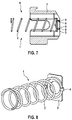
- Fig. 5
- die Baugruppe mit Federelement und Halteteil mit Rastvorsprüngen in modifizierter Ausführung, welche für eine formschlüssige Rastverbindung hergerichtet sind,
- Fig. 6
- die Bürstenanordnung mit eingesetztem Federelement, wobei die Rastvorsprünge an der Stirnfläche des Halteteils in zugeordnete Ausnehmungen im Boden der Bürstenhalterung eingeführt sind,
- Fig. 7
- einen Längsschnitt durch die Bürstenanordnung gemäß
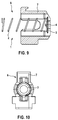
Fig. 6 , - Fig. 8
- eine weitere Darstellung einer Baugruppe mit einem Federelement und einem Halteteil,
- Fig. 9
- einen Schnitt durch eine Bürstenanordnung mit eingesetzter Baugruppe, wobei das Halteteil in die Wandung der Bürstenhalterung eingespritzt ist,
- Fig. 10
- eine Ansicht von vorne auf die Bürstenanordnung.
- Fig. 1
- a perspective view of an assembly of a brush assembly, consisting of a helical spring element and a holding part which is latchingly connected in the region of an end face with the spring element, wherein protrude to an end face of the holding part locking projections,
- Fig. 2
- a brush arrangement as part of a commutator device, with inserted assembly consisting of spring element and holding part,
- Fig. 3
- a section through the brush holder,
- Fig. 4
- another sectional view from a different perspective,
- Fig. 5
- the assembly with spring element and holding part with latching projections in modified design, which are prepared for a positive locking connection,
- Fig. 6
- the brush assembly with inserted spring element, wherein the latching projections are introduced at the end face of the holding part in associated recesses in the bottom of the brush holder,
- Fig. 7
- a longitudinal section through the brush assembly according to
Fig. 6 . - Fig. 8
- a further illustration of an assembly with a spring element and a holding part,
- Fig. 9
- a section through a brush assembly with inserted assembly, wherein the holding member is injected into the wall of the brush holder,
- Fig. 10
- a view from the front of the brush assembly.
In den Figuren sind gleiche Bauteile mit gleichen Bezugszeichen versehen.In the figures, the same components are provided with the same reference numerals.
In
Das Halteteil 3 ist an einem Ende des Federelementes 2 angeordnet. An der dem Federelement abgewandten Stirnfläche weist das Halteteil 3 einteilig ausgebildete Rastvorsprünge 5 auf, die sich in Richtung der Längsachse des Federelementes 2 erstrecken und über die Stirnfläche des Halteteils 3 axial hinausragen. Über die Rastvorsprünge 5 erfolgt eine rastschlüssige Verbindung mit einer Bürstenhalterung der Bürstenanordnung.The holding
In den
Das Federelement 2 beaufschlagt an seiner dem Halteteil 3 gegenüberliegenden Seite eine Kohlebürste in Richtung auf einen Kollektor, welcher drehfest mit der Motorwelle der elektrischen Maschine umläuft.The
Wie
In den
In den
Claims (12)
- Brush arrangement in a commutator device in an electrical machine, comprising at least one brush (10) which is displaceably guided in a brush holder (7) and to which force is applied by a spring element (2) which is held on a holding part (3) which is fixed to the brush holder (7), characterized in that the holding part (3) bears against an internal base of the pot-like brush holder (7) and is fixed to the wall of the brush holder (7).
- Brush arrangement according to Claim 1, characterized in that the brush holder (7) is in the form of an injection-moulded plastic part.
- Brush arrangement according to Claim 2, characterized in that the holding part (3) is injection-moulded into the wall of the brush holder (7).
- Brush arrangement according to one of Claims 1 to 3, characterized in that the holding part (3) is fixed to the base of the brush holder (7).
- Brush arrangement according to one of Claims 1 to 4, characterized in that the holding part (3) is held on the wall of the brush holder (7) in an interlocking manner.
- Brush arrangement according to one of Claims 1 to 5, characterized in that the holding part (3) is held on the wall of the brush holder (7) in a force-fitting manner.
- Brush arrangement according to one of Claims 1 to 6, characterized in that the holding part (3) is held on the wall of the brush holder (7) by means of latching elements.
- Brush arrangement according to Claim 7, characterized in that at least one latching projection (5) is arranged on the holding part (3) and projects into an associated recess (8) in the wall of the brush holder (7).
- Brush arrangement according to Claim 8, characterized in that the latching projection (5) has a latching hook (9) which, in the mounted position, is accommodated with an undercut in the recess (8) in the wall of the brush holder (7).
- Brush arrangement according to one of Claims 1 to 9, characterized in that the spring element (2) is connected to the holding part (3) by means of connecting elements (4) which are integrally formed with the holding part (3).
- Commutator device in an electrical machine comprising a brush arrangement (6) according to one of Claims 1 to 10.
- Electrical machine comprising a commutator device according to Claim 11.
Applications Claiming Priority (1)
| Application Number | Priority Date | Filing Date | Title |
|---|---|---|---|
| DE201010064234 DE102010064234A1 (en) | 2010-12-28 | 2010-12-28 | Brush arrangement in a commutator device in an electrical machine |
Publications (2)
| Publication Number | Publication Date |
|---|---|
| EP2472679A1 EP2472679A1 (en) | 2012-07-04 |
| EP2472679B1 true EP2472679B1 (en) | 2016-07-13 |
Family
ID=45566801
Family Applications (1)
| Application Number | Title | Priority Date | Filing Date |
|---|---|---|---|
| EP11194228.0A Active EP2472679B1 (en) | 2010-12-28 | 2011-12-19 | Brush assembly in a commutator device in an electric machine |
Country Status (5)
| Country | Link |
|---|---|
| EP (1) | EP2472679B1 (en) |
| CN (1) | CN102570230B (en) |
| DE (1) | DE102010064234A1 (en) |
| HU (1) | HUE030214T2 (en) |
| PL (1) | PL2472679T3 (en) |
Families Citing this family (1)
| Publication number | Priority date | Publication date | Assignee | Title |
|---|---|---|---|---|
| CN106159625B (en) * | 2016-08-10 | 2018-03-27 | 张宏伟 | The automatic mobile device of generator carbon brush component |
Family Cites Families (7)
| Publication number | Priority date | Publication date | Assignee | Title |
|---|---|---|---|---|
| US2474601A (en) * | 1948-03-19 | 1949-06-28 | Gen Electric | Brush mechanism |
| JPH0448134Y2 (en) * | 1987-05-29 | 1992-11-12 | ||
| US5872414A (en) * | 1995-02-07 | 1999-02-16 | Sawafuji Electric Co., Ltd | Electric rotating machine |
| CN1203592C (en) * | 2001-12-10 | 2005-05-25 | 三菱电机株式会社 | Electric brush holder for rotary motor |
| JP2005223974A (en) | 2004-02-03 | 2005-08-18 | Nidec Shibaura Corp | Fixing structure for brush in dc motor |
| JP2008125202A (en) * | 2006-11-10 | 2008-05-29 | Hitachi Appliances Inc | Brush device for commutator motor and vacuum cleaner |
| US7402933B1 (en) * | 2007-08-16 | 2008-07-22 | Phoenix Electric Mfg. Co. | Constant force modular integrated internal brush holder |
-
2010
- 2010-12-28 DE DE201010064234 patent/DE102010064234A1/en not_active Withdrawn
-
2011
- 2011-12-19 HU HUE11194228A patent/HUE030214T2/en unknown
- 2011-12-19 PL PL11194228T patent/PL2472679T3/en unknown
- 2011-12-19 EP EP11194228.0A patent/EP2472679B1/en active Active
- 2011-12-28 CN CN201110461375.4A patent/CN102570230B/en active Active
Also Published As
| Publication number | Publication date |
|---|---|
| PL2472679T3 (en) | 2017-01-31 |
| EP2472679A1 (en) | 2012-07-04 |
| DE102010064234A1 (en) | 2012-06-28 |
| CN102570230B (en) | 2016-05-18 |
| HUE030214T2 (en) | 2017-04-28 |
| CN102570230A (en) | 2012-07-11 |
Similar Documents
| Publication | Publication Date | Title |
|---|---|---|
| EP1851830B1 (en) | Connection system, in particular electrical connection system | |
| DE3529208C2 (en) | ||
| EP2807383B1 (en) | Fixing system | |
| DE102007017243A1 (en) | Machine tool, in particular hand tool | |
| DE3629634C2 (en) | ||
| WO2010130520A1 (en) | Hand-held power tool, in particular electric hand-held power tool | |
| EP2435210B1 (en) | Tool machine, in particular hand tool machine | |
| DE102015108831A1 (en) | Locking system for a charging plug | |
| EP2998485A1 (en) | Rotary knob for actuating a cylinder adapter of a closing cylinder | |
| DE102009026516A1 (en) | Machine tool, in particular hand tool | |
| WO2013020571A1 (en) | Hand-held blender | |
| DE60315799T2 (en) | Connection terminal for electric motor | |
| DE102008000732A1 (en) | Hand tool, in particular hand-guided grinding machine | |
| EP2472679B1 (en) | Brush assembly in a commutator device in an electric machine | |
| EP2745025B1 (en) | Transmission drive assembly | |
| DE102009002969A1 (en) | Electric hand-held machine tool i.e. angular grinder, has vibration reduction elements arranged between housing parts, where elements form-fittingly interconnect housing parts in spatial direction | |
| WO2009115143A1 (en) | Hand-held machine tool, in particular hand-guided grinding machine | |
| EP2005556B1 (en) | Plastic element | |
| EP2268450B1 (en) | Hand-held machine tool, in particular hand-guided grinding machine | |
| WO2015154755A1 (en) | Camshaft adjuster having a positive locking guide slot | |
| EP3482480A1 (en) | Fastening arrangement of an electric motor and seat | |
| DE202006019194U1 (en) | Gear unit of an adjustment and housing of such a gear unit | |
| DE10035254B4 (en) | Closure element for the housing of the engine of a motor vehicle starter and starter with such a closure element | |
| EP3317950B1 (en) | Connectionsystem for plug positioning | |
| DE202014007116U1 (en) | Electrical connectors |
Legal Events
| Date | Code | Title | Description |
|---|---|---|---|
| AK | Designated contracting states |
Kind code of ref document: A1 Designated state(s): AL AT BE BG CH CY CZ DE DK EE ES FI FR GB GR HR HU IE IS IT LI LT LU LV MC MK MT NL NO PL PT RO RS SE SI SK SM TR |
|
| AX | Request for extension of the european patent |
Extension state: BA ME |
|
| PUAI | Public reference made under article 153(3) epc to a published international application that has entered the european phase |
Free format text: ORIGINAL CODE: 0009012 |
|
| 17P | Request for examination filed |
Effective date: 20130104 |
|
| GRAP | Despatch of communication of intention to grant a patent |
Free format text: ORIGINAL CODE: EPIDOSNIGR1 |
|
| INTG | Intention to grant announced |
Effective date: 20160315 |
|
| GRAS | Grant fee paid |
Free format text: ORIGINAL CODE: EPIDOSNIGR3 |
|
| GRAA | (expected) grant |
Free format text: ORIGINAL CODE: 0009210 |
|
| AK | Designated contracting states |
Kind code of ref document: B1 Designated state(s): AL AT BE BG CH CY CZ DE DK EE ES FI FR GB GR HR HU IE IS IT LI LT LU LV MC MK MT NL NO PL PT RO RS SE SI SK SM TR |
|
| REG | Reference to a national code |
Ref country code: GB Ref legal event code: FG4D Free format text: NOT ENGLISH |
|
| REG | Reference to a national code |
Ref country code: AT Ref legal event code: REF Ref document number: 812978 Country of ref document: AT Kind code of ref document: T Effective date: 20160715 Ref country code: CH Ref legal event code: EP |
|
| REG | Reference to a national code |
Ref country code: IE Ref legal event code: FG4D Free format text: LANGUAGE OF EP DOCUMENT: GERMAN |
|
| REG | Reference to a national code |
Ref country code: DE Ref legal event code: R096 Ref document number: 502011010150 Country of ref document: DE |
|
| REG | Reference to a national code |
Ref country code: LT Ref legal event code: MG4D |
|
| REG | Reference to a national code |
Ref country code: NL Ref legal event code: MP Effective date: 20160713 |
|
| REG | Reference to a national code |
Ref country code: FR Ref legal event code: PLFP Year of fee payment: 6 |
|
| PG25 | Lapsed in a contracting state [announced via postgrant information from national office to epo] |
Ref country code: HR Free format text: LAPSE BECAUSE OF FAILURE TO SUBMIT A TRANSLATION OF THE DESCRIPTION OR TO PAY THE FEE WITHIN THE PRESCRIBED TIME-LIMIT Effective date: 20160713 Ref country code: NO Free format text: LAPSE BECAUSE OF FAILURE TO SUBMIT A TRANSLATION OF THE DESCRIPTION OR TO PAY THE FEE WITHIN THE PRESCRIBED TIME-LIMIT Effective date: 20161013 Ref country code: RS Free format text: LAPSE BECAUSE OF FAILURE TO SUBMIT A TRANSLATION OF THE DESCRIPTION OR TO PAY THE FEE WITHIN THE PRESCRIBED TIME-LIMIT Effective date: 20160713 Ref country code: IS Free format text: LAPSE BECAUSE OF FAILURE TO SUBMIT A TRANSLATION OF THE DESCRIPTION OR TO PAY THE FEE WITHIN THE PRESCRIBED TIME-LIMIT Effective date: 20161113 Ref country code: LT Free format text: LAPSE BECAUSE OF FAILURE TO SUBMIT A TRANSLATION OF THE DESCRIPTION OR TO PAY THE FEE WITHIN THE PRESCRIBED TIME-LIMIT Effective date: 20160713 Ref country code: FI Free format text: LAPSE BECAUSE OF FAILURE TO SUBMIT A TRANSLATION OF THE DESCRIPTION OR TO PAY THE FEE WITHIN THE PRESCRIBED TIME-LIMIT Effective date: 20160713 Ref country code: NL Free format text: LAPSE BECAUSE OF FAILURE TO SUBMIT A TRANSLATION OF THE DESCRIPTION OR TO PAY THE FEE WITHIN THE PRESCRIBED TIME-LIMIT Effective date: 20160713 |
|
| PG25 | Lapsed in a contracting state [announced via postgrant information from national office to epo] |
Ref country code: PT Free format text: LAPSE BECAUSE OF FAILURE TO SUBMIT A TRANSLATION OF THE DESCRIPTION OR TO PAY THE FEE WITHIN THE PRESCRIBED TIME-LIMIT Effective date: 20161114 Ref country code: LV Free format text: LAPSE BECAUSE OF FAILURE TO SUBMIT A TRANSLATION OF THE DESCRIPTION OR TO PAY THE FEE WITHIN THE PRESCRIBED TIME-LIMIT Effective date: 20160713 Ref country code: GR Free format text: LAPSE BECAUSE OF FAILURE TO SUBMIT A TRANSLATION OF THE DESCRIPTION OR TO PAY THE FEE WITHIN THE PRESCRIBED TIME-LIMIT Effective date: 20161014 Ref country code: SE Free format text: LAPSE BECAUSE OF FAILURE TO SUBMIT A TRANSLATION OF THE DESCRIPTION OR TO PAY THE FEE WITHIN THE PRESCRIBED TIME-LIMIT Effective date: 20160713 Ref country code: ES Free format text: LAPSE BECAUSE OF FAILURE TO SUBMIT A TRANSLATION OF THE DESCRIPTION OR TO PAY THE FEE WITHIN THE PRESCRIBED TIME-LIMIT Effective date: 20160713 |
|
| REG | Reference to a national code |
Ref country code: DE Ref legal event code: R097 Ref document number: 502011010150 Country of ref document: DE |
|
| PG25 | Lapsed in a contracting state [announced via postgrant information from national office to epo] |
Ref country code: RO Free format text: LAPSE BECAUSE OF FAILURE TO SUBMIT A TRANSLATION OF THE DESCRIPTION OR TO PAY THE FEE WITHIN THE PRESCRIBED TIME-LIMIT Effective date: 20160713 Ref country code: EE Free format text: LAPSE BECAUSE OF FAILURE TO SUBMIT A TRANSLATION OF THE DESCRIPTION OR TO PAY THE FEE WITHIN THE PRESCRIBED TIME-LIMIT Effective date: 20160713 |
|
| REG | Reference to a national code |
Ref country code: HU Ref legal event code: AG4A Ref document number: E030214 Country of ref document: HU |
|
| PLBE | No opposition filed within time limit |
Free format text: ORIGINAL CODE: 0009261 |
|
| STAA | Information on the status of an ep patent application or granted ep patent |
Free format text: STATUS: NO OPPOSITION FILED WITHIN TIME LIMIT |
|
| PG25 | Lapsed in a contracting state [announced via postgrant information from national office to epo] |
Ref country code: SK Free format text: LAPSE BECAUSE OF FAILURE TO SUBMIT A TRANSLATION OF THE DESCRIPTION OR TO PAY THE FEE WITHIN THE PRESCRIBED TIME-LIMIT Effective date: 20160713 Ref country code: BG Free format text: LAPSE BECAUSE OF FAILURE TO SUBMIT A TRANSLATION OF THE DESCRIPTION OR TO PAY THE FEE WITHIN THE PRESCRIBED TIME-LIMIT Effective date: 20161013 Ref country code: BE Free format text: LAPSE BECAUSE OF NON-PAYMENT OF DUE FEES Effective date: 20161231 Ref country code: DK Free format text: LAPSE BECAUSE OF FAILURE TO SUBMIT A TRANSLATION OF THE DESCRIPTION OR TO PAY THE FEE WITHIN THE PRESCRIBED TIME-LIMIT Effective date: 20160713 Ref country code: SM Free format text: LAPSE BECAUSE OF FAILURE TO SUBMIT A TRANSLATION OF THE DESCRIPTION OR TO PAY THE FEE WITHIN THE PRESCRIBED TIME-LIMIT Effective date: 20160713 Ref country code: CZ Free format text: LAPSE BECAUSE OF FAILURE TO SUBMIT A TRANSLATION OF THE DESCRIPTION OR TO PAY THE FEE WITHIN THE PRESCRIBED TIME-LIMIT Effective date: 20160713 |
|
| 26N | No opposition filed |
Effective date: 20170418 |
|
| REG | Reference to a national code |
Ref country code: CH Ref legal event code: PL |
|
| GBPC | Gb: european patent ceased through non-payment of renewal fee |
Effective date: 20161219 |
|
| PG25 | Lapsed in a contracting state [announced via postgrant information from national office to epo] |
Ref country code: SI Free format text: LAPSE BECAUSE OF FAILURE TO SUBMIT A TRANSLATION OF THE DESCRIPTION OR TO PAY THE FEE WITHIN THE PRESCRIBED TIME-LIMIT Effective date: 20160713 |
|
| PG25 | Lapsed in a contracting state [announced via postgrant information from national office to epo] |
Ref country code: MC Free format text: LAPSE BECAUSE OF FAILURE TO SUBMIT A TRANSLATION OF THE DESCRIPTION OR TO PAY THE FEE WITHIN THE PRESCRIBED TIME-LIMIT Effective date: 20160713 |
|
| REG | Reference to a national code |
Ref country code: IE Ref legal event code: MM4A |
|
| PG25 | Lapsed in a contracting state [announced via postgrant information from national office to epo] |
Ref country code: CH Free format text: LAPSE BECAUSE OF NON-PAYMENT OF DUE FEES Effective date: 20161231 Ref country code: LI Free format text: LAPSE BECAUSE OF NON-PAYMENT OF DUE FEES Effective date: 20161231 Ref country code: LU Free format text: LAPSE BECAUSE OF NON-PAYMENT OF DUE FEES Effective date: 20161219 |
|
| REG | Reference to a national code |
Ref country code: DE Ref legal event code: R081 Ref document number: 502011010150 Country of ref document: DE Owner name: SEG AUTOMOTIVE GERMANY GMBH, DE Free format text: FORMER OWNER: ROBERT BOSCH GMBH, 70469 STUTTGART, DE |
|
| PG25 | Lapsed in a contracting state [announced via postgrant information from national office to epo] |
Ref country code: IE Free format text: LAPSE BECAUSE OF NON-PAYMENT OF DUE FEES Effective date: 20161219 Ref country code: GB Free format text: LAPSE BECAUSE OF NON-PAYMENT OF DUE FEES Effective date: 20161219 |
|
| REG | Reference to a national code |
Ref country code: FR Ref legal event code: PLFP Year of fee payment: 7 |
|
| REG | Reference to a national code |
Ref country code: HU Ref legal event code: FH1C Free format text: FORMER REPRESENTATIVE(S): SBGK SZABADALMI UEGYVIVOEI IRODA, HU Representative=s name: SBGK SZABADALMI UEGYVIVOEI IRODA, HU Ref country code: HU Ref legal event code: GB9C Owner name: SEG AUTOMOTIVE GERMANY GMBH, DE Free format text: FORMER OWNER(S): ROBERT BOSCH GMBH, DE |
|
| REG | Reference to a national code |
Ref country code: BE Ref legal event code: MM Effective date: 20161231 |
|
| REG | Reference to a national code |
Ref country code: AT Ref legal event code: MM01 Ref document number: 812978 Country of ref document: AT Kind code of ref document: T Effective date: 20161219 |
|
| REG | Reference to a national code |
Ref country code: FR Ref legal event code: TP Owner name: SEG AUTOMOTIVE GERMANY GMBH, DE Effective date: 20180315 |
|
| PG25 | Lapsed in a contracting state [announced via postgrant information from national office to epo] |
Ref country code: CY Free format text: LAPSE BECAUSE OF FAILURE TO SUBMIT A TRANSLATION OF THE DESCRIPTION OR TO PAY THE FEE WITHIN THE PRESCRIBED TIME-LIMIT Effective date: 20160713 Ref country code: AT Free format text: LAPSE BECAUSE OF NON-PAYMENT OF DUE FEES Effective date: 20161219 |
|
| PG25 | Lapsed in a contracting state [announced via postgrant information from national office to epo] |
Ref country code: TR Free format text: LAPSE BECAUSE OF FAILURE TO SUBMIT A TRANSLATION OF THE DESCRIPTION OR TO PAY THE FEE WITHIN THE PRESCRIBED TIME-LIMIT Effective date: 20160713 Ref country code: MK Free format text: LAPSE BECAUSE OF FAILURE TO SUBMIT A TRANSLATION OF THE DESCRIPTION OR TO PAY THE FEE WITHIN THE PRESCRIBED TIME-LIMIT Effective date: 20160713 |
|
| PG25 | Lapsed in a contracting state [announced via postgrant information from national office to epo] |
Ref country code: MT Free format text: LAPSE BECAUSE OF FAILURE TO SUBMIT A TRANSLATION OF THE DESCRIPTION OR TO PAY THE FEE WITHIN THE PRESCRIBED TIME-LIMIT Effective date: 20160713 |
|
| PG25 | Lapsed in a contracting state [announced via postgrant information from national office to epo] |
Ref country code: AL Free format text: LAPSE BECAUSE OF FAILURE TO SUBMIT A TRANSLATION OF THE DESCRIPTION OR TO PAY THE FEE WITHIN THE PRESCRIBED TIME-LIMIT Effective date: 20160713 |
|
| REG | Reference to a national code |
Ref country code: DE Ref legal event code: R082 Ref document number: 502011010150 Country of ref document: DE Representative=s name: DEHNSGERMANY PARTNERSCHAFT VON PATENTANWAELTEN, DE |
|
| PGFP | Annual fee paid to national office [announced via postgrant information from national office to epo] |
Ref country code: FR Payment date: 20221214 Year of fee payment: 12 Ref country code: DE Payment date: 20220623 Year of fee payment: 12 |
|
| PGFP | Annual fee paid to national office [announced via postgrant information from national office to epo] |
Ref country code: PL Payment date: 20221209 Year of fee payment: 12 Ref country code: HU Payment date: 20221217 Year of fee payment: 12 |
|
| PGFP | Annual fee paid to national office [announced via postgrant information from national office to epo] |
Ref country code: IT Payment date: 20221222 Year of fee payment: 12 |