EP2472471B1 - System und Verfahren zur automatischen Ausrichtung eines Teleskops ohne Eingreifen des Benutzers - Google Patents
System und Verfahren zur automatischen Ausrichtung eines Teleskops ohne Eingreifen des Benutzers Download PDFInfo
- Publication number
- EP2472471B1 EP2472471B1 EP11192670.5A EP11192670A EP2472471B1 EP 2472471 B1 EP2472471 B1 EP 2472471B1 EP 11192670 A EP11192670 A EP 11192670A EP 2472471 B1 EP2472471 B1 EP 2472471B1
- Authority
- EP
- European Patent Office
- Prior art keywords
- pointing error
- processor
- aggregate
- error
- time offset
- Prior art date
- Legal status (The legal status is an assumption and is not a legal conclusion. Google has not performed a legal analysis and makes no representation as to the accuracy of the status listed.)
- Active
Links
Images


Classifications
-
- G—PHYSICS
- G01—MEASURING; TESTING
- G01S—RADIO DIRECTION-FINDING; RADIO NAVIGATION; DETERMINING DISTANCE OR VELOCITY BY USE OF RADIO WAVES; LOCATING OR PRESENCE-DETECTING BY USE OF THE REFLECTION OR RERADIATION OF RADIO WAVES; ANALOGOUS ARRANGEMENTS USING OTHER WAVES
- G01S3/00—Direction-finders for determining the direction from which infrasonic, sonic, ultrasonic, or electromagnetic waves, or particle emission, not having a directional significance, are being received
- G01S3/78—Direction-finders for determining the direction from which infrasonic, sonic, ultrasonic, or electromagnetic waves, or particle emission, not having a directional significance, are being received using electromagnetic waves other than radio waves
- G01S3/782—Systems for determining direction or deviation from predetermined direction
- G01S3/785—Systems for determining direction or deviation from predetermined direction using adjustment of orientation of directivity characteristics of a detector or detector system to give a desired condition of signal derived from that detector or detector system
- G01S3/786—Systems for determining direction or deviation from predetermined direction using adjustment of orientation of directivity characteristics of a detector or detector system to give a desired condition of signal derived from that detector or detector system the desired condition being maintained automatically
- G01S3/7867—Star trackers
-
- G—PHYSICS
- G02—OPTICS
- G02B—OPTICAL ELEMENTS, SYSTEMS OR APPARATUS
- G02B23/00—Telescopes, e.g. binoculars; Periscopes; Instruments for viewing the inside of hollow bodies; Viewfinders; Optical aiming or sighting devices
- G02B23/16—Housings; Caps; Mountings; Supports, e.g. with counterweight
Definitions
- the present invention relates to methods and systems for automatically aligning a telescope to point to a desired celestial location.
- Many telescopes are capable of automatically pointing to particular coordinates given in terms of right ascension and declination, and/or to specified celestial objects by looking up the celestial coordinate locations of such objects in a database.
- Such operations are usually enabled by the use of a specialized motor-driven mount and associated software for controlling the positioning of the mount via a microprocessor or other control device.
- Such an apparatus is generally referred to as a "GoTo" mount.
- Conventional GoTo mounts generally perform alignment by reference to a known location and/or date/time, as well as one or more reference objects, such as particular celestial objects.
- a user is generally required to input local date, time and location, and to manually point the telescope toward the reference object, which may be for example a particular star (referred to as an "alignment star").
- the reference object which may be for example a particular star (referred to as an "alignment star").
- two or more alignment stars are used, so as to improve accuracy.
- Knowledge of the actual location of the alignment star(s) in right ascension and declination, as well as local time and date enables the telescope to generate a transform that defines a relationship between internal coordinates and celestial coordinates.
- Various GoTo mounts have different alignment techniques. Some require the user to manually center certain reference stars in the eyepiece, so that alignment can be performed with respect to these reference stars. Others require time and location information to be manually input or determined via Global Positioning System (GPS) or other methods, and/or the sensing of bright stars.
- GPS Global Positioning System
- McWilliams U.S. Patent Publication No., US2004/0233521 A1 , entitled “Automatic Telescope", published November 25, 2004, describes an automatic telescope that does not require user input of time and/or location.
- the telescope aligns itself by scanning the sky for two or more bright stars that are used as alignment references.
- its method of operation can require multiple sensing iterations, including image capture and analysis, in order to locate sufficiently bright reference stars.
- the requirement for independent bright reference stars can increase the time to achieve an alignment, and can cause the apparatus to fail to align in situations where it is not possible to detect a sufficient number of bright reference stars.
- such a technique requires that the apparent magnitudes of stars be compared with one another so that bright stars can be detected.
- Some self-aligning telescopes utilize GPS for time and location acquisition, combined with a digital compass and an accelerometer-based level-sensing apparatus to orient the mount during initial alignment.
- An example of a supplier of such telescopes is Meade Instruments Corp. of Irvine, California.
- these telescopes can introduce additional complexity and cost, as the final product must include such components as the GPS, digital compass, accelerometer, and image capture devices.
- at least some telescopes of this type use star brightness in their determination of the alignment reference position, which introduce similar limitations to those discussed above in connection with McWilliams.
- the present invention provides a method, a system and a computer program product for aligning a telescope according to claims 1, 16 and 29 respectively.
- a system and method of automatically aligning a telescope without requiring knowledge of actual local time or geographic location (latitude and longitude), and without relying on sensing bright stars or relative (or absolute) star magnitudes; accordingly, the system and method of the present invention are able to operate in situations where such bright stars are not visible.
- the techniques of the present invention address the problems and limitations of conventional self-alignment methods, and do not require user intervention or substantial additional equipment such as GPS systems, digital compasses, and accelerometers.
- a telescope is aligned by generating a mathematical transform, also referred to as a "mount model".
- the mount model is a coordinate transformation that defines the relationship between a telescope's internal coordinate system and a celestial coordinate system.
- the mount model is generated using an arbitrary time and date, arbitrary telescope location (specified, for example, as longitude and latitude), and a number of alignment reference points (such as, for example, three alignment reference points).
- the alignment reference points are a set of captured data for some number of positions of the telescope.
- An initial mount model is generated based on data corresponding to these alignment reference points, each including an arbitrary local sidereal time (LST) (a celestial time reference associated with the location of observation) and an internal telescopic coordinate reference (based, for example, on internal motor positioning routines).
- LST local sidereal time
- internal telescopic coordinate reference based, for example, on internal motor positioning routines.
- the system and method of the present invention is able to operate without knowledge of the actual local time and location.
- An initial LST is derived from the arbitrary time and location (for example, using the arbitrary local time and arbitrary longitude to calculate the initial LST).
- the arbitrary time and location can be initialized from pre-programmed values, if desired.
- Initial values of LST and latitude are successively refined using an iterative process that measures pointing error between expected and observed star locations, as described below.
- the iterative process generates an LST offset, representing the difference between actual LST at the location and LST calculated from the initial arbitrary time and longitude.
- the system and method operate as follows.
- a star field is captured, for example using an image capture device such as a camera.
- a matching process is performed to attempt to match stars in the captured field with known patterns of stars.
- This step which is referred to as "plate solving" yields a mathematical transform that relates pixel coordinates of an image with celestial coordinates in right ascension and declination. No relative brightness determination is needed.
- an initial mount model is generated.
- the LST and latitude are corrected via an iterative process, as described herein.
- the degree of error in the initial mount model is determined, for example using root-mean-square (RMS) calculation and/or some other statistical error measurement technique, based on observation of some number of alignment reference points.
- RMS root-mean-square
- This RMS pointing error represents the accuracy of the determined coordinate transformation, and reflects an indication of error in the initial LST and/or latitude values with respect to the alignment reference points.
- Iterative adjustment is performed, wherein offset adjustments are successively added to the LST of each alignment reference point, and/or wherein the latitude of the mount model is successively corrected. Pointing errors are measured at each iteration. Results are evaluated so as to arrive at a minimized RMS pointing error with respect to the alignment reference points.
- a final accumulated LST offset is determined, representing the difference between actual LST and LST derived from the initial arbitrary time and location. This LST offset is saved, for application to any LST calculations, and the corrected latitude is retained in the mount model.
- a two-phased approach for deriving the LST offset and latitude correction is applied.
- offsets of one hour are applied to LST values for each of the alignment reference points, so as to arrive at a coarse approximation of the mount model.
- a second phase is performed, wherein the LST offset (and/or the latitude) is/are fine-tuned to further minimize RMS pointing error, to arrive at the final LST offset and latitude values.
- LST offset and latitude have been determined with sufficient accuracy so that the telescope has been aligned.
- Actual LST can be determined by applying the LST offset to the LST derived from the initial arbitrary time and location, and the mount model can then be used for GoTo pointing operations.
- the iterative optimization process of the present invention replaces the need for a GPS, and further avoids the need for the user to manually provide the local time and location.
- the system and method of the present invention provide a technique for aligning a telescope without requiring manual user input and without introducing a need for significant additional hardware at added expense.
- the system and method of the present invention do not require time, location, or relative star brightness information to perform telescope alignment.
- the system and method of the present invention do not require any alignment to a local horizon coordinate system, and indeed do not require that true horizon coordinates be known.
- the techniques of the present invention can be implemented with an altitude-azimuth mount, wherein the axes of rotation are approximately aligned to the horizon coordinate system, or an equatorial mount, or any other type of mount.
- the present invention can be implemented within a telescope or other device for generating or capturing celestial images, and/or within a mount or other apparatus for controlling and adjusting the positioning of such a telescope.
- the present invention can be implemented within a computing device or other electronic device that can be communicatively coupled with a telescope or other imaging device, for example to send signals to a microcontroller for controlling and adjusting the positioning of the telescope.
- the present invention can be implemented in a device that is mechanically coupled to a telescope and which adjusts the position of the telescope, for example by mechanical coupling with the telescope mount.
- a mechanical bracket can be used for such mechanical coupling.
- the system of the present invention can operate in connection with an existing mount and telescope. Users can then purchase the system of the present invention for use with their existing equipment.
- the system of the present invention can use existing GoTo electronics of the telescope and/or mount, with additional functionality as described herein.
- the present invention can be used for alignment of any type of telescope or combination of telescopes, including but not limited to optical telescopes, radio telescopes, x-ray telescopes, gamma ray telescopes, arrays of telescopes, and the like.
- the present invention can also be used for alignment of any other type of device for observing celestial objects.
- the invention can be implemented on a stand-alone electronic device, or on a plurality of electronic devices communicatively coupled with one another, such as for example in a client/server environment wherein some components are client-based and other components are server-based.
- Each such electronic device may be, for example, a personal computer, handheld computer, personal digital assistant (PDA), kiosk, cellular telephone, or the like.
- An electronic network enabling communication among two or more electronic devices may be implemented using well-known network protocols such as Hypertext Transfer Protocol (HTTP), Secure Hypertext Transfer Protocol (SHTTP), Transmission Control Protocol / Internet Protocol (TCP/IP), and/or the like.
- HTTP Hypertext Transfer Protocol
- SHTTP Secure Hypertext Transfer Protocol
- TCP/IP Transmission Control Protocol / Internet Protocol
- Such a network may be, for example, the Internet or an Intranet.
- the invention can be used to adjust a telescope based on celestial data provided from a local source, such as a local storage device, and/or based on celestial data from a star databases located at a server which may be local or remote with respect to the telescope.
- a local source such as a local storage device
- celestial data from a star databases located at a server which may be local or remote with respect to the telescope.
- the techniques described herein can be implemented on any other type of computing device, combination of devices, or platform. Any or all of such devices can, in one embodiment, operate under the direction and control of software.
- the present invention is implemented as a software application running on a computing device, consumer electronic device, telescope, imaging device, or the like.
- the software application may be a desktop application or a web-based application that is accessible via a browser such as Microsoft Internet Explorer®, available from Microsoft Corporation® of Redmond, Washington, or by a specialized web-based client application.
- the software application runs on a personal computer or other device that is communicatively coupled with a microcontroller for adjusting the position of a telescope or telescope mount.
- the invention can operate in connection with live images (i.e., images as they are being captured) and/or previously captured images with associated telescope position and LST values. Images can be provided in any form, whether electronic, optical, photographic, or the like.
- live images i.e., images as they are being captured
- images can be provided in any form, whether electronic, optical, photographic, or the like.
- digital image and “plate” herein are used herein for ease of nomenclature, and no limitation to particular forms or media is intended or should be implied.
- Fig. 1 there is shown a diagram depicting a self-aligning telescope 109 according to one embodiment of the present invention.
- the invention can be implemented in telescope 109 as a stand-alone unit, or in communication with a separate electronic device for controlling the adjustment of telescope 109.
- the particular depiction shown in Fig. 1 is merely exemplary and is not intended to limit the scope of the claimed invention.
- telescope 109 includes optical tube assembly 111 which can be of any known type, including reflecting, refracting, or catadioptric.
- Telescope can include any known image capture device 113, such as for example a charge-coupled device (CCD) camera, complementary metal-oxide semiconductor (CMOS) camera, active-pixel sensor (APS) camera, or the like.
- CCD charge-coupled device
- CMOS complementary metal-oxide semiconductor
- APS active-pixel sensor
- Telescope 109 is attached to mount 119 via attachment 112, which may for example be a dovetail attachment.
- mount 119 is electrically controlled by a microcontroller (not shown in Fig. 1 ), so that it can be adjusted automatically in accordance with the techniques described herein.
- mount 119 includes power input jack 114, which may be, for example, a 12-volt direct current (DC) power input jack; keypad 115 for user input of commands and data to control telescope 109; and on/off switch 117. In one embodiment, mount 119 sits on tripod 118 for stability.
- power input jack 114 which may be, for example, a 12-volt direct current (DC) power input jack
- keypad 115 for user input of commands and data to control telescope 109
- on/off switch 117 In one embodiment, mount 119 sits on tripod 118 for stability.
- mount 119 includes dual-axis drive base 116 which permits movement of telescope 109 along two axes, thus facilitating automatic alignment according to the techniques described herein.
- dual-axis drive base 116 which permits movement of telescope 109 along two axes, thus facilitating automatic alignment according to the techniques described herein.
- the techniques of the present invention can be implemented with any type of drive base.
- Mount 119 may be of any type, including for example an altitude-azimuth mount, wherein the axes of rotation are approximately aligned to the horizon coordinate system, or an equatorial mount, or any other type of mount 119.
- telescope 109 includes an internal clock (not shown in Fig. 1 ), for keeping track of time with respect to an arbitrary local sidereal time, as described in more detail below.
- FIG. 2 there is shown a block diagram depicting an architecture for implementing a self-aligning telescope 109 in connection with a computing device 101, according to one embodiment of the present invention.
- Such an architecture can be used, for example, for implementing the techniques of the present invention in connection with a stand-alone software application running on a computer or other computing device communicatively coupled to telescope 109 or other imaging device.
- the system of the present invention operates, in part, by analyzing images captures by telescope 109. Accordingly, telescope 109 provides image 110 via any known communications mechanism, whether wired or wireless.
- Image 110 may be a digital image, photographic image, optical image, or any other type of image; image 110 is variously referred to herein as an "image”, “digital image”, or “plate”, but usage of such various terms should not be considered to limit the scope of the invention to any particular type or format of image.
- Computing device 101 may be any electronic device adapted to run software; for example, computing device 101 may be a desktop computer, laptop computer, personal digital assistant, smartphone, music player, handheld computer, tablet computer, kiosk, game system, or the like. Alternatively, computing device 101 can be a component of telescope 109 itself, either bundled with telescope 109 or purchased as an add-on. In one embodiment, computing device 101 is a desktop computer running an operating system such as Microsoft Windows®, available from Microsoft Corporation® of Redmond, Washington, or a smartphone such as the Apple iPhone®, available from Apple Inc. ® of Cupertino, California, or a tablet computer such as the Apple iPad®, available from Apple Inc. ® of Cupertino, California.
- Microsoft Windows® available from Microsoft Corporation® of Redmond, Washington
- a smartphone such as the Apple iPhone®, available from Apple Inc. ® of Cupertino, California
- a tablet computer such as the Apple iPad®, available from Apple Inc. ® of Cupertino, California.
- computing device 101 comprises a number of hardware components as are well known to those skilled in the art.
- Input device 102 can be a keyboard, mouse, touchscreen, trackball, trackpad, five-way switch, voice input device, joystick, and/or any combination thereof.
- Output device 103 can be a screen, speaker, printer, and/or any combination thereof.
- Processor 104 can be a conventional microprocessor for performing operations on data under the direction of software, according to well-known techniques.
- Memory 105 can be random-access memory having a structure and architecture as are known in the art, for use by processor 104 in the course of running software.
- Local storage 106 can be any magnetic, optical, and/or electrical storage device for storage of data in digital form; examples include flash memory, magnetic hard drive, CD-ROM, and/or the like.
- local storage 106 includes star database 107, which contains information describing the positions of celestial objects, for use in connection with the present invention to align telescope 109, as described in more detail herein.
- Computing device 101 includes telescope control interface 121, which sends control signals 122 to microcontroller 120 of telescope 109, in order to perform automatic alignment of telescope 109.
- Microcontroller 120 can be implemented as any electronic and/or mechanical device for changing the position of telescope 109 in accordance with control signals 122.
- control signals 122 are sent over a wired connection; in another embodiment, they are sent wirelessly.
- microcontroller 120 is designed or equipped to receive control signals 122 and position telescope 109 accordingly.
- telescope 109 includes internal clock 123, for keeping track of time with respect to an arbitrary local sidereal time, as described in more detail below.
- telescope 109 includes image capture device 113, such as a camera, for capturing images 110 for example in digital, optical, video, and/or photographic form.
- FIG. 2 One skilled in the art will recognize that the particular arrangement of hardware elements shown in Fig. 2 is merely exemplary, and that the invention can be implemented using different hardware elements configured in any of a number of different ways. Thus, the particular architecture shown in Fig. 2 is merely illustrative and is not intended to limit the scope of the claimed invention in any way.
- FIG. 3 there is shown a block diagram depicting a hardware architecture for practicing the present invention in a client/server environment according to one embodiment of the present invention.
- Such an architecture can be used, for example, for implementing the techniques of the present invention in connection with a web-based application for aligning telescope 109.
- processor 104 runs browser software according to well known mechanisms.
- Network communications interface 203 is an electronic component that facilitates communication of data to and from other computing devices over communications network 201.
- Communications network 201 can be the Internet or any other electronic communications network.
- Server 202 communicates with computing device 101 over network 201, and in one embodiment can be located remotely or locally with respect to computing device 101.
- server 202 is associated with data store 108, which contains star database 107 including information describing the positions of celestial objects, for use in connection with the present invention to align telescope 109, as described in more detail herein.
- star database 107 can be located at server 202 or at computing device 101.
- star database 107 (or some portion thereof) can be transmitted to computing device 101 as part of a client/server session, to improve responsiveness and performance.
- the present invention may be implemented using a distributed software architecture if appropriate.
- client/server architecture shown in Fig. 3 is merely exemplary, and that other architectures can be used to implement the present invention, including architectures that are not necessarily web-based.
- the particular architecture shown in Fig. 3 is merely illustrative and is not intended to limit the scope of the invention in any way.
- the alignment method of the present invention generates a mount model that telescope 109 can use for translating between an internal coordinate system (expressed, for example in terms of positions along primary and secondary axes) and a celestial coordinate system (expressed, for example in terms of right ascension and declination).
- the mount model is generated by capturing some number of alignment reference points (such as, for example, three alignment reference points) relating the internal coordinate system, along with a time reference in terms of local sidereal time (LST), and the celestial coordinate system for a number of positions. This information, taken with local LST and geographic (latitude and longitude) information about the observation location, yields a mount model that mathematically relates internal coordinates and celestial coordinates.
- telescope 109 can be used for GoTo operations wherein the user instructs telescope 109 to point to particular celestial coordinates or to a particular celestial object.
- the mount model is, in one embodiment, expressed as a mathematical transform that defines the relationship between the internal coordinate system of telescope 109 and the celestial coordinate system.
- the relationship between internal coordinates and celestial coordinates depends on the local time and location. The relationship changes with the passage of time, due to the rotation of the earth; this apparent motion of celestial objects (such as stars) is referred to as sidereal motion.
- sidereal motion As a result, for a given celestial coordinate, the internal coordinates representing telescope 109 position changes over time.
- LST is the hour angle of the vernal equinox at a given location. It can also be expressed as the right ascension of the meridian dividing the east and west halves of the celestial sphere at a given location.
- LST can be derived for a particular observation location, for example, based on local time at the location, time zone at the location, and longitude at the location. From the local time and time zone, it is possible to calculate Universal Time (UT). UT and the longitude of the observation location are used to derive LST by calculating the offset from UT based on the longitude (every 15 degrees of longitude is equivalent to one hour of offset).
- the mount model also takes into account the latitude of the observation location.
- the relationship specified by the mount model is based on the following equations, which calculate right ascension and declination ( ⁇ , ⁇ ) of the celestial coordinates from the horizon coordinates azimuth and altitude ( A,h ):
- the mount model of the present invention can also correct for various imperfections in telescope 109, according to techniques that are well known in the art.
- errors include, for example, an offset in the coordinate system from the setup of the telescope, errors in the orthogonality of the axes, flexure in the mechanics of the mount, errors in gear trains, atmospheric refraction, and the like.
- error correction techniques are not discussed in detail here, as they are not required in order to practice the present invention.
- the mount model is generated without requiring knowledge of the actual time and location. Rather, an arbitrary time and location are used.
- An LST referred to herein as "arbitrary LST"
- the mount model is generated using the above-described techniques, using the arbitrary LST and location, with a recognition that some initially unknown LST offset exists between actual LST and the arbitrary LST.
- a mathematical transform is derived; however, the transform is generally inaccurate owing to the difference between the arbitrary LST and actual LST (i.e., the LST offset) and further owing to the different between the arbitrary latitude and the actual latitude (i.e., the latitude error).
- a transformation of telescopic coordinates to celestial coordinates using the derived transform will generally produce pointing errors, and/or potentially errors in other parameters of the mount model.
- the transform is iteratively adjusted based on measurement of pointing errors until a sufficiently accurate mount model is generated.
- multiple linear regression is employed in order to iteratively reduce the pointing error.
- an RMS pointing error for the initial mounting model is measured; this RMS pointing error describes the accuracy of the mount model given the alignment points used, along with the individual pointing error for these alignment points.
- the estimated north/south polar misalignment (or latitude error) can also be measured. The latitude angle at a location corresponds to the angle of the polar axis of rotation from the horizon at a given location.
- Statistical feedback information derived from the alignment process provides visibility into the effects of the LST offset and/or latitude error. Adjustments can then be made, for example by changing parameters such as LST offset and/or latitude, in order to refine the accuracy of the model in an iterative manner. With each iteration, a new LST offset adjustment and new latitude adjustment are determined, and a new RMS pointing error is calculated. The iterative process proceeds, with adjustments being made based on measurement of expected positions of celestial objects with actual observed positions. The goal is to reduce RMS pointing error, and by doing so, determine 1) the actual LST offset between initial arbitrary LST and actual LST for the observation location, and 2) the correct actual latitude for the observation location. By making successive adjustments in this manner, the system of the present invention is able to generate LST and latitude values that approach actual values. Once the RMS pointing error is determined to be sufficiently small, the process ends.
- the RMS pointing error represents the accuracy of the coordinate transformation.
- the iterative process used by the present invention to minimize the RMS pointing error produces LST offsets and a corrected latitude that closely approximate the actual LST and the actual latitude of the observation location.
- the iterative process generates both an LST offset and a latitude value.
- LST offset adjustments are successively applied to a working value of the LST offset, effectively moving the LST of an alignment reference point around so that changes in RMS pointing error can be observed, and so that RMS pointing error can be minimized.
- the iterative process also generates a latitude value. Since the initial latitude is set at an arbitrary value, this initial latitude is typically incorrect and does not reflect the actual location of the observer. When alignment reference points are added, this incorrect latitude produces errors in the expected pointing accuracy of the model (RMS pointing error), as well as the reported accuracy of the alignment references.
- the mount model may report what appears to be a polar misalignment, which is actually attributable (at least in part) to latitude error. Reprogramming the latitude value in the mount model produces an observable change in the RMS pointing error. This adjustment in latitude can be performed iteratively, along with the iterative adjustment of LST offset, so as to reduce RMS pointing error and arrive at an improved mount model.
- telescope 109 is initialized upon power-up, in order to make it ready for automatic alignment.
- Fig. 5 there is shown is a flow diagram depicting a method for initializing telescope 109 according to one embodiment of the present invention.
- the method of Fig. 5 can be used in connection with telescope 109 as depicted in Figs. 1 , 2 , and/or 3, although one skilled in the art will recognize that the method can also be practiced with other types of apparatus of different designs.
- telescope in the descriptions provided herein is for ease of nomenclature only, and should not be construed as limiting the invention to operating solely with telescopes; to the contrary, the techniques of the present invention can be implemented in connection with any device for capturing or viewing images.
- the method begins 500.
- the steps of Fig. 5 are performed when telescope 109 is initially powered on.
- the steps may be performed when the user presses a Reset button (not shown), or when some other problem or condition occurs which indicates that initialization should take place. Some steps may be performed at different stages after being powered on, as when a user initiates an automatic alignment.
- Telescope 109 initializes 501 its time and location. In one embodiment, there is no requirement for telescope 109 to use actual current time and location. Rather, the techniques of the present invention can be implemented using any arbitrary time and location.
- time can refer to "date and time”.
- the result of step 501 includes initial values for date and time 504, LST offset 505, and location (expressed, for example, as latitude/longitude 506).
- the primary and secondary axis positions 507 of telescope 109 are initialized 502.
- the primary axis is initialized to zero, based on the current arbitrary orientation of telescope mount 119.
- the secondary axis is initialized according to a limit sensor for an approximate level position, and a range of motion protection.
- a limit switch is used to manage the limits of travel, such as for example to specify limits of five degrees below horizontal, and five degrees deviation from vertical.
- the system of the present invention assumes an approximate level position by determining the lowest permissible position and measuring upwards by five degrees.
- One skilled in the art will recognize that other values may be used depending on the particular characteristics of the mount and telescope 109.
- Mount model 535 is initialized 503 using the initialized latitude/longitude values 506, date and time 504, and LST offset 505.
- the system of the present invention is able to perform alignment for telescope 109 in the absence of actual local time and location information.
- the alignment methodology uses LST derived from an arbitrary time and location.
- This arbitrary time and location as initialized in steps 501 and 502 may be pre-programmed, for example to some fixed value, such as a time/date of to January 1, 2010 at 6:00PM, and a location of 33o 50' 41" latitude, and 118o 20' 17" longitude.
- the arbitrary time and longitude are used to calculate the LST; additionally, the latitude may be used in the mount model for certain calculations.
- telescope 109 (and/or computing device 101) uses internal clock 123 to keep track of elapsed time with respect to the arbitrary initialized time, for alignment operations.
- telescope 109 is ready 599 for alignment according to the techniques described herein.
- FIG. 4 there is shown a flow diagram depicting an overview of a method for automatically aligning telescope 109 according to one embodiment of the present invention.
- Fig. 4 depicts a feedback loop that is employed to make adjustments in an iterative fashion, based on measured RMS pointing error, so as to refine the mount model until a sufficient level of accuracy is achieved with respect to LST offset and corrected latitude.
- the method begins 400.
- An initial mount model is generated 401, based on an arbitrary time and location.
- An overall RMS pointing error is measured 402, for example based on observed pointing errors for some number of alignment reference points.
- overall RMS pointing error is measured 402 by adjusting LST offset for each alignment reference and/or adjusting the latitude programmed to the mount model, to produce a measurement of the overall pointing accuracy and mount model accuracy. If, in step 403, the overall RMS pointing error is sufficiently small (for example, smaller than some threshold value), changes are saved 405 to the LST offset and latitude parameters in the mount model, and the method ends 499. If, in step 403, the RMS pointing error is not sufficiently small, LST offset and latitude parameters in the mount model are adjusted 406, the adjusted LST offset is applied to the LST value for each alignment reference point 404, and the method returns to step 402.
- Fig. 6 there is shown is a flow diagram depicting additional details of a method for automatically aligning a telescope according to one embodiment of the present invention.
- the method begins 520.
- Primary and secondary axes 507 of telescope 109 are moved 522 to a prospective position for an alignment reference point.
- a position is selected to be sufficiently far away from previously captured alignment reference points, in terms of azimuth and altitude.
- the selection of prospective position takes in to account any failed alignment reference point capture attempts if any.
- the method might select prospective positions such as (expressed in azm,alt):
- step 1 fails to provide a suitable alignment reference point.
- step 1 fails to provide a suitable alignment reference point.
- the axes are moved 522 by controlling drive base 116 of mount 199, for example via microcontroller 120. In an embodiment including a separate computing device 101, such an operation can take place under the direction of control signals 122.
- An image 110 is captured 523 at the position, for example using image capture device 113 of telescope 109.
- image 110 is a digital image, although in other embodiments, image 110 can take any suitable form.
- image 110 is also referred to herein as a "plate”.
- LST Local sidereal time
- the marked LST 533 does not necessarily reflect actual LST; rather it is calculated 526 from arbitrary values for date and time 504, LST offset 505, and latitude/longitude, as initialized in step 501 and/or adjusted by offset in the iterative process described herein. Marked LST 533 can also take into account elapsed time since initialization of telescope 109.
- LST 533 is marked 524 by marking LST 533 at the start and end image capture 523, and taking the midpoint of the two marked times.
- plate solving the system attempts to determine 525 celestial coordinates 536 of captured image 110, for example by determining the location of some set of candidate celestial objects (such as stars) in captured image 110. In one embodiment, this is done by attempting to match the candidate stars against patterns of stars in star database 107.
- the system of the present invention uses one or more techniques for determining celestial coordinates of an image as described in related U.S. Patent Application Serial No. 2010/0983065 for "Determining Celestial Coordinates for an Image", attorney docket number CEL001, filed on the same date as the present application, the disclosure of which is incorporated herein by reference.
- the system of the present invention in determining 525 celestial coordinates 536 of captured image 110, takes into account any number of stars, which may include all stars that it can detect in image 110, or any portion thereof. Thus, according to one embodiment, the system does not require any brightness-sensing or brightness-comparison steps.
- celestial coordinates are determined by selecting some number of stars, such as four stars (referred to as a "quad"), determining telescopic (x,y) coordinates (also known as "plate coordinates”) for the selected stars, generating a signature based on coordinates for the selected stars, and searching for matches to the signature in database 107.
- Celestial coordinates 536 of captured image 110 are specified in terms of a mathematical coordinate transform referred to as a "plate solution". If, in step 527, a plate solution cannot be found for captured image 110, adjustments are made 528 for another attempt, and the system returns to step 523 to capture another image 110. Adjustments 528 may include, for example and without limitation, adjusting settings for the image capture device 113, moving mount 119 to a new prospective alignment position, and/or the like. In one embodiment, after some number of failed attempts, the system may quit or abandon the alignment process, or may prompt the user to move telescope 109 to another location and/or to enter some additional information manually.
- the system captures 529 information from the plate solution for alignment reference point 534.
- the captured information for alignment reference point 534 includes, for example: celestial coordinates 536 (in terms of right ascension and declination) for captured image 110; primary and secondary axis positions 507 of telescope 109 from mount 119; and LST calculated from the time of capture 504.
- the time of capture is represented as elapsed time from clock 123 initialization.
- An estimate of LST 533 is generated, based on the time of capture, arbitrary location, determined celestial coordinates for captured image 110, and axis positions.
- Mount model 535 is then adjusted in accordance with this information 534 for the alignment reference point.
- Mount model 535 includes mathematical transforms for translating between telescopic and celestial coordinates.
- mount model 535 also includes a measurement of pointing error with respect to initial arbitrary time and location 504.
- three alignment reference points are used, although one skilled in the art will recognize that any number can be used. If at least one more alignment reference point is to be analyzed 531, the system returns to step 522 to repeat the above-described steps for the next alignment reference point.
- iterative optimization is performed 532 to adjust LST offset and latitude so as to minimize pointing errors in mount model 535 that result from the difference between the arbitrary LST and latitude and actual LST and latitude. Additional details for iterative optimization are described in connection with Figs. 7 and 8 . Once the iterative optimization has been performed 532, mount model 535 is sufficiently accurate; the method ends 598 and telescope 109 has been properly aligned.
- iterative optimization 532 is performed in a two-step manner: in a first phase, referred to as Phase I, a coarse adjustment of LST offset is performed; in a second phase, referred to as Phase II, a fine adjustment of LST and/or latitude is performed.
- Phase I involves coarse adjustment of the LST offset of mount model 535 to within one hour of actual LST. This is done by applying 24 successive offsets, in increments of one hour each, to each of the alignment reference points. Thus, 24 prospective values of LST offset are used in this phase. For each prospective value, RMS pointing error is evaluated; the offset that generates the smallest pointing error is considered to be the best initial estimate of actual LST offset.
- Fig. 7 there is shown a flow diagram depicting a method for coarse adjustment of the LST offset, according to one embodiment of the present invention.
- the method begins 700.
- the system performs a loop 24 times with successive offsets of LST having one-hour increments.
- RMS pointing error for 24 offsets is obtained, corresponding to the 24 hours in a sidereal day.
- the output of the coarse adjustment method of Fig. 7 is to determine which LST offset results in minimum RMS pointing error.
- the loop can be performed with smaller or larger increments any number of times, as appropriate.
- the loop begins at step 701. For each alignment reference point, the LST offset is adjusted 702 according to the current LST offset for the loop iteration, and the mount model 535 is recalculated. The RMS pointing error for mount model 535 is determined and compared 703 with any previously determined
- the system determines whether the current RMS pointing error is a new minimum. If so, the system saves 705 the minimum RMS pointing error value 706 as well as the LST offset 709 corresponding to that minimum RMS pointing error value. The loop ends 707.
- alignment reference point information 534 is updated by applying 534 the saved LST offset 709 corresponding to the minimum RMS pointing error 706 to the LST values for each alignment reference point.
- this saved LST offset 709 the method ensures that alignment reference point information 534 contains the LST offset that yields the lowest error among those offsets attempted in the coarse adjustment process. The method ends 799.
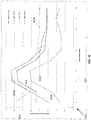
- a graph 900 depicting an example of results of a coarse adjustment of LST offset, according to one embodiment of the present invention.
- a root-mean-square (RMS) pointing error is measured for each of 24 LST offsets, in one-hour increments.
- X-axis 901 represents the LST offsets
- Y-axis 902 represents the pointing error, in arc-seconds.
- the RMS pointing error is a measure of the magnitude of the distance between the expected and actual location of the alignment reference point, in celestial coordinate space.
- plot 903A represents RMS pointing error for a first alignment reference point
- plot 903B represents pointing error for a second alignment reference point
- plot 903C represents RMS pointing error for a third alignment reference point.
- the total RMS pointing error 904 is generated by aggregating the individual RMS pointing errors 903.
- the lowest total RMS pointing error 904 is observed at an LST offset of 22 hours.
- the actual LST offset is within one hour of 22 hours, and this value is used for the next phase of optimization.
- Phase II further optimization is performed in an attempt to further fine-tune the LST offset to some defined degree of precision, such as, for example to within six minutes of actual LST offset.
- the system of the present invention also attempts to determine actual latitude of the observation location to some defined degree of precision, such as to within 10 arc-minutes (1/6 degree).
- An iterative process is performed, wherein, for each iteration, the north/south polar misalignment (also referred to as the latitude error) is checked. If this misalignment is greater than some tolerance value (such as, for example, 10 arc-minutes), then the mount model's latitude is adjusted by the amount of the reported error. If the north/south polar misalignment is less than or equal to the tolerance value, then the LST offset is adjusted by 6 minutes in a positive or negative direction depending on the perceived slope of the RMS pointing error.
- some tolerance value such as, for example, 10 arc-minutes
- Iterative adjustment of latitude and LST offset causes the RMS pointing error to be successively reduced. The adjustment steps are repeated until the RMS pointing error is below some threshold acceptable value, or until further adjustment is no longer able to reduce the RMS pointing error.
- LST offset adjustment 817 of mount model 535 is initialized 801 at some arbitrary direction and magnitude, for example at a value of +6 minutes, although any value can be used.
- Latitude error (north/south misalignment) of mount model 535 is measured 803 using the current LST offset. If the latitude error is less than some threshold value, such as 10 arc-minutes, then the method proceeds to step 808. If the latitude error is not less than the threshold value, then latitude is adjusted 805. Mount model 535 is recalculated with the adjusted latitude, and the method returns to step 803.
- RMS pointing error is measured, and the current RMS pointing error is saved 808 as RMS pointing error for comparison 810, so that changes to RMS pointing error can be measured.
- LST offset adjustment 817 is applied 809 to each alignment reference point.
- RMS pointing error is again measured based on mount model 535, and this new RMS pointing error is compared 811 with the previously stored RMS pointing error 810. If, in step 812, the new RMS pointing error is less than the previously stored RMS pointing error 810, the method returns to step 803.
- step 812 If, in step 812, the new RMS pointing error is not less than the previously stored RMS pointing error 810, then a determination is made 813 as to whether LST offset adjustment 817 has already been reversed.
- LST offset adjustment 817 is reversed 814 and the method returns to step 803. If LST offset adjustment 817 has already been reversed, then the method reverts 815 to the previous LST offset for each alignment reference point. The sum 818 of the LST offset adjustments that were applied is saved 816 as the determined LST offset 505; this LST offset 505 is then output, stored, and/or transmitted 898 as a result. The method ends 899.
- a graph 1000 depicting an example of results of a fine adjustment of LST offset for the same alignment reference points as considered in Fig. 9 , according to one embodiment of the present invention.
- an RMS pointing error is measured at each step of the iterative optimization process.
- X-axis 1001 represents the optimization step
- Y-axis 1002 represents the RMS pointing error, again given in arc-seconds.
- plot 903A represents RMS pointing error for a first alignment reference point
- plot 903B represents RMS pointing error for a second alignment reference point
- plot 903C represents RMS pointing error for a third alignment reference point, although any number of alignment points can be used.
- RMS pointing error 904 is also shown in graph 1000 .
- successive adjustments are made until RMS pointing error 904 no longer improves over the previous step.
- RMS pointing error 904 is approaching 1.5 arc-minutes at step 8, but begins to increase again at step 9. Accordingly, in one embodiment, the iterative process would stop at step 8, and the adjustments made at that step would be considered to represent minimum RMS pointing error.
- the LST offset and latitude values are set to those of step 8 (as can be seen at step 10, where a final adjustment to LST is made), and the RMS pointing error is considered minimized.
- the LST for the alignment reference points shown in Fig. 10 were derived from an arbitrary time, such as 18:00 on January 1, 2010. LST was determined as 00h, 53m. After optimization, the LST with offsets was around 22h 41 m, which reflects the correct LST for the location at the time of alignment. Additionally, the arbitrary latitude was set to 23o N, and after the optimization, this was adjusted to within 1 degree of the actual latitude of 33.8o N for the location.
- Table 1 depicts an example of the raw data for each iteration of the Phase II optimization process as depicted in Fig. 10 .
- the column labeled “Operation” shows “LAT” for latitude adjustment, “LST” for LST adjustment, and “FIN” for the final optimization value.
- the "RMS Pointing Error” column shows the RMS pointing error approaching a minimum value of about 1.55 arc-minutes. Also shown are the pointing errors for each of the three alignment reference points.
- the LST offset at the start is 22 hours (as it was at the end of Phase I operation). It is adjusted in +/- 6 minute increments for each LST operation until the RMS pointing error minimum is detected.
- the LST offset at the end of optimization is 21 h 48m, and the latitude error is 6.2 arc-minutes, which reflects the actual LST and latitude of the location with a high degree of accuracy.
- Table 1 Latitude Error LST Offset RMS Pointing Error Alignment Reference Point RMS Pointing Error (Before) Step Operation Before After Before After Before After Align 1 Align 2 Align 3 1 LAT 551.6 1.3 22h 0m 22h 0m 2.21652 2.19228 1.454167 3.465249 0.780369 2 LST 1.3 10.9 22h 0m 22h 6m 2.19228 3.2856 2.499242 2.554246 1.28228 3 LAT 10.9 -0.2 22h 6m 22h 6m 3.2856 3.37296 3.589008 3.647449 2.488929 4 LST -0.2 -9.8 22h 6m 22h 0m 3.37296 2.24958 3.688702 3.72308 2.581748 5 LST -9
- step 1 a latitude adjustment is performed, since the magnitude of the latitude error (north/south misalignment) is 551.6 arcminutes, which is greater than 10 arcminutes (step 804). In one embodiment, RMS pointing error is not considered during latitude adjustments.
- step 2 magnitude of the latitude error is 1.3, so no latitude adjustment is made. Instead, an LST offset adjustment of +6 minutes is performed. RMS pointing error increases, so the LST offset adjustment is reversed (step 814) to -6 minutes for the next LST adjustment.
- step 3 latitude adjustment is performed, since the magnitude of the latitude error is 10.9 arcminutes, which is again greater than 10 arcminutes.
- steps 4 and 5 magnitude of the latitude error is below 10 arcminutes, so no latitude adjustment is made.
- LST offset adjustment of -6 minutes is performed in each of these steps.
- RMS pointing error decreases at each step, so no reversal is performed.
- step 6 magnitude of the latitude error is again above 10 arcminutes, so a latitude adjustment is performed.
- step 7 an LST adjustment is made. RMS pointing error decreases.
- step 8 an LST adjustment is again made. RMS pointing error increases. Since the offset adjustment has already been reversed (step 813), the iterative loop is exited.
- step 9 LST reverts to the previous LST offset (step 815) from step 7.
- step 10 the process is complete, with a final LST offset of 21 h 48m and a latitude error of -6.2.
- the present invention can be implemented as a system or a method for performing the above-described techniques, either singly or in any combination.
- the present invention can be implemented as a computer program product comprising a nontransitory computer-readable storage medium and computer program code, encoded on the medium, for causing a processor in a computing device or other electronic device to perform the above-described techniques.
- Reference in the specification to "one embodiment” or to “an embodiment” means that a particular feature, structure, or characteristic described in connection with the embodiments is included in at least one embodiment of the invention.
- the appearances of the phrase "in one embodiment" in various places in the specification are not necessarily all referring to the same embodiment.
- Certain aspects of the present invention include process steps and instructions described herein in the form of an algorithm. It should be noted that the process steps and instructions of the present invention can be embodied in software, firmware and/or hardware, and when embodied in software, can be downloaded to reside on and be operated from different platforms used by a variety of operating systems.
- the present invention also relates to an apparatus for performing the operations herein.
- This apparatus may be specially constructed for the required purposes, or it may comprise a general-purpose computing device selectively activated or reconfigured by a computer program stored in the computing device.
- a computer program may be stored in a nontransitory computer readable storage medium, such as, but is not limited to, any type of disk including floppy disks, optical disks, CD-ROMs, magnetic-optical disks, read-only memories (ROMs), random access memories (RAMs), EPROMs, EEPROMs, magnetic or optical cards, application specific integrated circuits (ASICs), or any type of media suitable for storing electronic instructions, and each coupled to a computer system bus.
- the computing devices referred to herein may include a single processor or may be architectures employing multiple processor designs for increased computing capability. Any reference to a "processor” herein can thus be considered to apply to a single processor or to any number of processors, either installed in one or a plurality of devices. Such processor or processors can be in one or more computing devices and/or in any other electronic device or devices, located proximate to or remote to one another.
- the present invention can be implemented as software, hardware, and/or other elements for controlling a computer system, computing device, or other electronic device, or any combination or plurality thereof.
- an electronic device can include, for example, a processor, an input device (such as a keyboard, mouse, touchpad, trackpad, joystick, trackball, microphone, and/or any combination thereof), an output device (such as a screen, speaker, and/or the like), memory, long-term storage (such as magnetic storage, optical storage, and/or the like), and/or network connectivity, according to techniques that are well known in the art.
- Such an electronic device may be portable or nonportable.
- Examples of electronic devices that may be used for implementing the invention include: a mobile phone, personal digital assistant, smartphone, kiosk, desktop computer, laptop computer, tablet computer, consumer electronic device, television, set-top box, or the like.
- An electronic device for implementing the present invention may use any operating system such as, for example, Microsoft Windows® available from Microsoft Corporation® of Redmond, Washington, MacOS® available from Apple Inc. ® of Cupertino, California, or any other operating system that is adapted for use on the device.
Landscapes
- Physics & Mathematics (AREA)
- General Physics & Mathematics (AREA)
- Engineering & Computer Science (AREA)
- Radar, Positioning & Navigation (AREA)
- Remote Sensing (AREA)
- Astronomy & Astrophysics (AREA)
- Optics & Photonics (AREA)
- Electromagnetism (AREA)
- Position Fixing By Use Of Radio Waves (AREA)
- Image Processing (AREA)
- Telescopes (AREA)
- Studio Devices (AREA)
Claims (23)
- Verfahren zum Ausrichten eines Teleskops (109) dadurch gekennzeichnet, dass das Verfahren umfasst:a) Erstellen eines beliebigen Anfangszeitwertes und eines beliebigen Anfangsdatumswertes ohne Bezug auf eine tatsächliche Zeit und ein tatsächliches Datum in einem Prozessor (104);b) Erstellen eines beliebigen Anfangspositionswertes ohne Bezug auf eine tatsächliche Position in dem Prozessor;c) Initialisieren eines Montierungsmodells auf Basis des Anfangszeitwertes, Anfangsdatumswertes und Anfangspositionswertes in dem Prozessor, wobei das Montierungsmodell eine mathematische Transformation zwischen einem Teleskopkoordinatensystem und einem Himmelskoordinatensystem spezifiziert;d) Messen eines Richtfehlers für das Montierungsmodell unter Bezug auf mehrere Ausrichtungsbezugspunkte in dem Prozessor auf Basis des Zeit-, Datums- und Positionswertes und Kumulieren der gemessenen Richtfehler, wobei die Ausrichtungsbezugspunkte einen Satz von für eine Anzahl von Positionen des Teleskops erfassten Daten darstellen und die Zeitwerte auf Basis der beliebigen Zeit und Position für jeden Ausrichtungsbezugspunkt berechnet werden; unde) iteratives Korrigieren des Zeit- und/oder Datums- und/oder Positionswertes in dem Prozessor, um den Kumulationsrichtfehler des Montierungsmodells zu vermindern; undf) Durchführen zumindest eines von Folgendem:und wobei Schritt e) ferner umfasst:Ausgeben des Montierungsmodells an einer Ausgabevorrichtung;Speichern des Montierungsmodells in einer Speichervorrichtung; undAnwenden des Montierungsmodells in dem Prozessor zum Ausrichten des Teleskops;e.1) Durchführen einer Grobeinstellung des lokalen Sternzeitversatzes in einer ersten Phase, unde.2) Durchführen einer iterativen Feineinstellung des lokalen Sternzeitversatzes und/oder Breitengrades in einer zweiten Phase, indem bei jeder Iteration die Nord/Süd-Fehljustierung geprüft wird; und
wenn die polare Nord/Süd-Polarfehljustierung größer als ein Toleranzwert ist, Korrigieren des Breitengrades des Montierungsmodells um den Betrag des Fehljustierungsfehlers; oder
wenn die polare Nord/Süd-Polarfehljustierung kleiner oder gleich dem Toleranzwert ist, Korrigieren des lokalen Sternzeitversatzes in eine Richtung, die von der ermittelten Steigung des Kumulationsrichtfehlers abhängt. - Verfahren nach Anspruch 1, wobei Schritt e) umfasst, in dem Prozessor den Zeit- und/oder Datums- und/oder Positionswert iterativ zu korrigieren, bis der Kumulationsrichtfehler kleiner als ein vorgegebener Schwellwert ist.
- Verfahren nach Anspruch 1, wobei Schritt e) umfasst, in dem Prozessor den Zeit- und/oder Datums- und/oder Positionswert iterativ zu korrigieren, bis der Kumulationsrichtfehler für eine Iteration nicht kleiner als der Kumulationsrichtfehler für eine unmittelbar vorangegangene Iteration ist.
- Verfahren nach Anspruch 1, wobei Schritt d) umfasst, in dem Prozessor:die gemessenen Richtfehler zum Erzeugen eines RMS (Root-Mean-Square; Quadratmittel)-Kumulationsrichtfehlers zu kumulieren; und wobei Schritt e) umfasst, in dem Prozessor den Zeitund/oder Datums- und/oder Positionswert iterativ zu korrigieren, um den RMS-Kumulationsrichtfehler zu verkleinern.
- Verfahren nach Anspruch 1, wobei der beliebige Anfangszeitwert und der beliebige Anfangsdatumswert eine zufällig bestimmte lokale Sternzeit umfassen.
- Verfahren nach Anspruch 1, wobei Schritt d) umfasst, für zumindest einen Ausrichtungsbezugspunkt:d.1) an einer Bildaufnahmevorrichtung ein Bild in einer dem Ausrichtungsbezugspunkt entsprechenden Richtung aufzunehmen;d.2) in dem Prozessor die dem aufgenommenen Bild entsprechenden Himmelskoordinaten zu bestimmen; undd.3) in dem Prozessor zumindest ein Element des aufgenommenen Bildes mit für die bestimmten Himmelskoordinaten gespeicherten Daten zu vergleichen, um einen Richtfehler zu messen.
- Verfahren nach Anspruch 6, wobei Schritt d.2) umfasst:in dem Prozessor Plattenkoordinatenpositionen für mehrere Objekte in dem aufgenommenen Bild zu beziehen;in dem Prozessor eine Signatur aus den Plattenkoordinatenpositionen der Objekte zu erzeugen;in dem Prozessor eine übereinstimmende Signatur in einem Datenspeicher für Signaturen von Himmelsobjekten zu identifizieren; undaus dem Datenspeicher die Himmelskoordinaten der übereinstimmenden Signatur zu beziehen.
- Verfahren nach Anspruch 1, wobei Schritt e) umfasst,e.1) in dem Prozessor zu bestimmen, ob der Kumulationsrichtfehler des Montierungsmodells kleiner als ein Schwellwert ist;e.2) Speichern des Montierungsmodells in der Speichervorrichtung, wenn der Kumulationsrichtfehler kleiner als der Schwellwert ist; unde.3) wenn der Kumulationsrichtfehler nicht kleiner ist als der Schwellwert:Korrigieren eines lokalen Sternzeitversatzes und/oder eines Breitengradwertes in dem Prozessor;Messen des Kumulationsrichtfehlers des Montierungsmodells in dem Prozessor unter Bezug auf den zumindest einen Ausrichtungsbezugspunkt auf Basis des korrigierten zumindest einen Wertes; undWiederholen der Schritte e.1) bis e.3).
- Verfahren nach Anspruch 1, wobei Schritt e.1) umfasst:Messen des Richtfehlers des Montierungsmodells in dem Prozessor für jeden der mehreren lokalen Sternzeitversatzkorrekturwerte unter Bezug auf den zumindest einen Ausrichtungsbezugspunkt, wobei die mehreren lokalen Sternzeitversatzkorrekturwerte relativ zueinander eine feste Zeitschrittweite aufweisen;
undAuswählen des lokalen Sternzeitversatzkorrekturwertes, der mit dem kleinsten Richtfehler verknüpft ist, der unter Bezug auf den zumindest einen Ausrichtungsbezugspunkt gemessen wurde;
undAnwenden des gewählten lokalen Sternzeitversatzkorrekturwertes in dem Prozessor zum Korrigieren des lokalen Sternzeitversatzes. - Verfahren nach Anspruch 1, wobei Schritt e.2) umfasst:e.2.1) Messen eines Breitengradfehlers des Montierungsmodells in dem Prozessor unter Bezug auf den zumindest einen Ausrichtungsbezugspunkt;e.2.2) Korrigieren des Breitengradwertes in dem Prozessor, wenn der Breitengradfehler größer als ein vorgegebener Schwellwert ist;e.2.3) Durchführen einer lokalen Sternzeitversatzkorrektur in dem Prozessor;e.2.4) Messen des Richtfehlers des Montierungsmodells in dem Prozessor unter Bezug auf den zumindest einen Ausrichtungsbezugspunkt;e.2.5) Bestimmen, in dem Prozessor, ob der gemessene Richtfehler kleiner ist als der minimale Richtfehler;e.2.6) wenn der gemessene Richtfehler kleiner als der minimale Richtfehler ist: Wiederholen der Schritte e.2.1) bis e.2.6) solange, bis der gemessene Richtfehler unterhalb eines Schwellwertes liegt;e.2.7) Anwenden der zumindest einen korrigierten lokalen Sternzeitversatzkorrektur in dem Prozessor zur Bildung eines lokalen Sternzeitversatzes; unde.2.8) Anwenden des lokalen Sternzeitversatzes auf das Montierungsmodell.
- Verfahren nach Anspruch 1, wobei Schritt e.2) umfasst:e.2.1) Messen eines Breitengradfehlers des Montierungsmodells in dem Prozessor unter Bezug auf den zumindest einen Ausrichtungsbezugspunkt;e.2.2) Korrigieren des Breitengradwertes in dem Prozessor, wenn der Breitengradfehler größer als ein vorgegebener Schwellwert ist;e.2.3) Durchführen einer lokalen Sternzeitversatzkorrektur in dem Prozessor;e.2.4) Messen des Richtfehlers des Montierungsmodells in dem Prozessor unter Bezug auf den zumindest einen Ausrichtungsbezugspunkt;e.2.5) Bestimmen, in dem Prozessor, ob der gemessene Richtfehler kleiner ist als der minimale Richtfehler;e.2.6) wenn der gemessene Richtfehler kleiner als der minimale Richtfehler ist: Wiederholen der Schritte e.2.1) bis e.2.6) solange, bis der gemessene Richtfehler größer als ein bei einer vorhergehenden Iteration gemessener Richtfehler ist;e.2.7) Zurücksetzen der lokalen Sternzeitversatzkorrektur in dem Prozessor auf eine mit einem minimalen Richtfehler verknüpfte lokale Sternzeitversatzkorrektur; unde.2.8) Anwenden der zurückgesetzten lokalen Sternzeitversatzkorrektur auf das Montierungsmodell in dem Prozessor.
- Verfahren nach Anspruch 1, wobei Schritt e.2) umfasst:e.2.1) Initialisieren eines Wertes für einen minimalen Richtfehler in dem Prozessor;e.2.2) Messen eines Breitengradfehlers des Montierungsmodells in dem Prozessor unter Bezug auf den zumindest einen Ausrichtungsbezugspunkt;e.2.3) Korrigieren des Breitengradwertes in dem Prozessor, wenn der Breitengradfehler größer als ein vorgegebener Schwellwert ist;e.2.4) Durchführen einer lokalen Sternzeitversatzkorrektur in dem Prozessor;e.2.5) Messen des Richtfehlers des Montierungsmodells in dem Prozessor unter Bezug auf den zumindest einen Ausrichtungsbezugspunkt;e.2.6) Bestimmen, in dem Prozessor, ob der gemessene Richtfehler kleiner als der minimale Richtfehler ist;e.2.7) Wiederholen der Schritte e.2.2) bis e.2.7), wenn der gemessene Richtfehler kleiner als der minimale Richtfehler ist; unde.2.8) wenn der gemessene Richtfehler nicht kleiner als der minimale Richtfehler ist:Bestimmen, in dem Prozessor, ob die lokale Sternzeitversatzkorrektur zuvor zurückgesetzt wurde;wenn die lokale Sternzeitversatzkorrektur zuvor zurückgesetzt wurde:Zurücksetzen der lokalen Sternzeitversatzkorrektur in dem Prozessor auf eine mit dem minimalen Richtfehler verknüpfte lokale Sternzeitversatzkorrektur;Anwenden der zurückgesetzten lokalen Sternzeitversatzkorrektur auf das Montierungsmodell in dem Prozessor.
- System zum Ausrichten eines Teleskops (109), dadurch gekennzeichnet, dass das System aufweist:einen Prozessor (104), der zum Erstellen eines beliebigen Anfangszeitwertes, eines beliebigen Anfangsdatumswertes und eines beliebigen Anfangspositionswertes ohne Bezug auf eine tatsächliche Zeit, ein tatsächliches Datum und eine tatsächliche Position ausgebildet ist;ein Montierungsmodell, das zum Spezifizieren einer mathematische Transformation zwischen einem Teleskopkoordinatensystem und einem Himmelskoordinatensystem ausgebildet ist, wobei das Montierungsmodell auf Basis des Anfangszeitwertes, Anfangsdatumswertes und Anfangspositionswertes initialisiert wird;ein Richtfehlermessmodul, das zum Messen eines Richtfehlers des Montierungsmodells unter Bezug auf mehrere Ausrichtungsbezugspunkte auf Basis des Zeit-, Datums- und Positionswertes und zum Kumulieren der gemessenen Richtfehler ausgebildet ist, wobei die Ausrichtungsbezugspunkte einen Satz von für eine Anzahl von Positionen des Teleskops erfassten Daten darstellen und die Zeitwerte auf Basis der beliebigen Zeit- und beliebigen Position für jeden Ausrichtungsbezugspunkt berechnet werden;ein Iterationskorrekturmodul, das zum iterativen Korrigieren des Zeit- und/oder Datums- und/oder Positionswertes ausgebildet ist, um die Größe des kumulierten Fehlers des Montierungsmodells zu vermindern; undeinen Mikrokontroller, der zum Anwenden des Montierungsmodells ausgebildet ist, um das Teleskop auszurichten;und wobei das Iterationskorrekturmodul ferner ausgebildet ist zum:Durchführen einer Grobeinstellung des lokalen Sternzeitversatzes in einer ersten Phase, undDurchführen einer iterativen Feineinstellung des lokalen Sternzeitversatzes und/oder Breitengrades in einer zweiten Phase, indem bei jeder Iteration die Nord/Süd-Fehljustierung geprüft wird; undwenn die Nord/Süd-Polarfehljustierung größer als ein Toleranzwert ist, Korrigieren des Breitengrades des Montierungsmodells um den Betrag des Fehljustierungsfehlers; oderwenn die Nord/Süd-Polarfehljustierung kleiner oder gleich dem Toleranzwert ist, Korrigieren des lokalen Sternzeitversatzes in eine Richtung, die von der ermittelten Steigung des Kumulationsrichtfehlers abhängt.
- System nach Anspruch 13, wobei das Iterationskorrekturmodul ausgebildet ist, den Zeit- und/oder Datums- und/oder Positionswert iterativ zu korrigieren, bis der Kumulationsrichtfehler kleiner als ein vorgegebener Schwellwert ist.
- System nach Anspruch 13, wobei das Iterationskorrekturmodul ausgebildet ist, den Zeit- und/oder Datums- und/oder Positionswert iterativ zu korrigieren, bis der Kumulationsrichtfehler für eine Iteration nicht kleiner als der Kumulationsrichtfehler für eine unmittelbar vorangegangene Iteration ist.
- System nach Anspruch 13, wobei:das Richtfehlermessmodul ausgebildet ist, Richtfehler für mehrere Ausrichtungsbezugspunkte zu messen und die gemessenen Richtfehler zu kumulieren, um einen RMS (Root-Mean-Square;Quadratmittel)-Kumulationsrichtfehler zu erzeugen; unddas Iterationskorrekturmodul ausgebildet ist, den Zeit- und/oder Datums- und/oder Positionswert iterativ zu korrigieren, um den RMS-Kumulationsrichtfehler zu verkleinern.
- System nach Anspruch 13, wobei der beliebige Anfangszeitwert und der beliebige Anfangsdatumswert eine zufällig bestimmte lokale Sternzeit umfassen.
- System nach Anspruch 13, das ferner aufweist:eine Bildaufnahmevorrichtung, die ausgebildet ist, ein Bild in einer dem Ausrichtungsbezugspunkt entsprechenden Richtung aufzunehmen; wobei das Richtfehlermessmodul ausgebildet ist, dem aufgenommenen Bild entsprechende Himmelskoordinaten zu bestimmen und zumindest ein Element des aufgenommenen Bildes mit für die bestimmten Himmelskoordinaten gespeicherten Daten zu vergleichen, um den Kumulationsrichtfehler zu bestimmen.
- System nach Anspruch 18, das ferner aufweist:einen Datenspeicher für Signaturen von Himmelsobjekten; wobei das Richtfehlermessmodul ausgebildet ist, die dem aufgenommenen Bild entsprechenden Himmelskoordinaten zu bestimmen, indem:Plattenkoordinatenpositionen für mehrere Objekte in dem aufgenommenen Bild bezogen werden;eine Signatur aus den Plattenkoordinatenpositionen der Objekte erzeugt wird;eine übereinstimmende Signatur in dem Datenspeicher identifiziert wird; undaus dem Datenspeicher die Himmelskoordinaten für die übereinstimmenden Signatur bezogen werden.
- System nach Anspruch 13, wobei das Iterationskorrekturmodul zum iterativen Korrigieren des Zeit- und/oder Datums- und/oder Positionswertes ausgebildet ist, indem:e.1) in dem Prozessor bestimmt wird, ob der Kumulationsrichtfehler des Montierungsmodells kleiner als ein Schwellwert ist;e.2) das Montierungsmodell in der Speichervorrichtung gespeichert wird, wenn der Kumulationsrichtfehler kleiner als der Schwellwert ist; unde.3) wenn der Kumulationsrichtfehler nicht kleiner als der Schwellwert ist:ein lokaler Sternzeitversatz und/oder ein Breitengradwert korrigiert wird;das Kumulationsrichtfehlermessmodul zum Messen des Richtfehlers des Montierungsmodells unter Bezug auf den zumindest einen Ausrichtungsbezugspunkt auf Basis des korrigierten zumindest einen Wertes veranlasst wird; unddie Schritte e.1) bis e.3) wiederholt werden.
- System nach Anspruch 13, wobei das Iterationskorrekturmodul ausgebildet ist, eine iterative Grobeinstellung des lokalen Sternzeitversatzes durchzuführen, indem:das Richtfehlermessmodul für jeden der mehreren lokalen Sternzeitversatzkorrekturwerte zum Messen des Kumulationsrichtfehlers des Montierungsmodells unter Bezug auf den zumindest einen Ausrichtungsbezugspunkt veranlasst wird, wobei die mehreren lokalen Sternzeitversatzkorrekturwerte relativ zueinander eine feste Zeitschrittweite aufweisen; undder lokale Sternzeitversatzkorrekturwert ausgewählt wird, der mit dem kleinsten Kumulationsrichtfehler verknüpft ist, der unter Bezug auf den zumindest einen Ausrichtungsbezugspunkt gemessen wurde; undder gewählte lokale Sternzeitversatzkorrekturwert zum Korrigieren des lokalen Sternzeitversatzes verwendet wird.
- System nach Anspruch 13, wobei das Iterationskorrekturmodul ausgebildet ist, den lokalen Sternzeitversatz und/oder einen Breitengradwert zu korrigieren, durch:e.2.1) Initialisieren eines Wertes für einen minimalen Kumulationsrichtfehler;e.2.2) Veranlassen des Richtfehlermessmoduls zum Messen eines Breitengradfehlers des Montierungsmodells unter Bezug auf den zumindest einen Ausrichtungsbezugspunkt;e.2.3) Korrigieren des Breitengradwertes in dem Prozessor, wenn der Breitengradfehler größer als ein vorgegebener Schwellwert ist;e.2.4) Durchführen einer lokalen Sternzeitversatzkorrektur;e.2.5) Veranlassen des Richtfehlermessmoduls zum Messen des Kumulationsrichtfehlers des Montierungsmodells unter Bezug auf den zumindest einen Ausrichtungsbezugspunkt;e.2.6) Bestimmen, ob der gemessene Richtfehler kleiner als der minimale Kumulationsrichtfehler ist;e.2.7) Wiederholen der Schritte e.2.2) bis e.2.7), wenn der gemessene Kumulationsrichtfehler kleiner als der minimale Kumulationsrichtfehler ist; unde.2.8) wenn der gemessene Kumulationsrichtfehler nicht kleiner als der minimale Kumulationsrichtfehler ist:Bestimmen, ob die lokale Sternzeitversatzkorrektur zuvor zurückgesetzt wurde;wenn die lokale Sternzeitversatzkorrektur zuvor zurückgesetzt wurde:Zurücksetzen der lokalen Sternzeitversatzkorrektur auf eine mit dem minimalen Richtfehler verknüpfte lokale Sternzeitversatzkorrektur;Anwenden der zurückgesetzten lokalen Sternzeitversatzkorrektur auf das Montierungsmodell.
- Computerprogrammprodukt zum Ausrichten eines Teleskops (109), das aufweist:ein nichtflüchtiges, computerlesbares Speichermedium; und das gekennzeichnet ist durcheinen auf dem Medium codierten Computerprogrammcode, der ausgebildet ist, zumindest einen Prozessor (104) zur Durchführung der folgenden Schritte zu veranlassen:a) Erstellen eines beliebigen Anfangszeitwertes und eines beliebigen Anfangsdatumswertes ohne Bezug auf eine tatsächliche Zeit und ein tatsächliches Datum;b) Erstellen eines beliebigen Anfangspositionswertes ohne Bezug auf eine tatsächliche Position;c) Initialisieren eines Montierungsmodells auf Basis des Anfangszeitwertes, Anfangsdatumswertes und Anfangspositionswertes, wobei das Montierungsmodell eine mathematische Transformation zwischen einem Teleskopkoordinatensystem und einem Himmelskoordinatensystem spezifiziert;d) Messen eines Richtfehlers für das Montierungsmodell unter Bezug auf mehrere Ausrichtungsbezugspunkte auf Basis des Zeit-, Datums- und Positionswertes und Kumulieren der gemessenen Richtfehler; unde) iteratives Korrigieren des Zeit- und/oder Datums- und/oder Positionswertes, um den Kumulationsrichtfehler des Montierungsmodells zu vermindern; undf) Durchführen zumindest einem von Folgendem:Ausgeben des Montierungsmodells;Speichern des Montierungsmodells in einer Speichervorrichtung; undAnwenden des Montierungsmodells zum Ausrichten des Teleskops;und wobei Schritt e) ferner umfasst:e.1) Durchführen einer Grobeinstellung des lokalen Sternzeitversatzes in einer ersten Phase, unde.2) Durchführen einer iterativen Feineinstellung des lokalen Sternzeitversatzes und/oder Breitengrades in einer zweiten
Phase, indem bei jeder Iteration die Nord/Süd-Fehljustierung geprüft wird; und
wenn die Nord/Süd-Polarfehljustierung größer als ein Toleranzwert ist, Korrigieren des Breitengrades des Montierungsmodells um den Betrag des Fehljustierungsfehlers; oder
wenn die Nord/Süd-Polarfehljustierung kleiner oder gleich dem Toleranzwert ist, Korrigieren des lokalen Sternzeitversatzes in eine Richtung, die von der ermittelten Steigung des Kumulationsrichtfehlers abhängt.
Applications Claiming Priority (1)
| Application Number | Priority Date | Filing Date | Title |
|---|---|---|---|
| US12/983,085 US8477419B1 (en) | 2010-12-31 | 2010-12-31 | System and method for automatically aligning a telescope without requiring user intervention |
Publications (3)
| Publication Number | Publication Date |
|---|---|
| EP2472471A2 EP2472471A2 (de) | 2012-07-04 |
| EP2472471A3 EP2472471A3 (de) | 2012-08-29 |
| EP2472471B1 true EP2472471B1 (de) | 2017-06-14 |
Family
ID=45406435
Family Applications (1)
| Application Number | Title | Priority Date | Filing Date |
|---|---|---|---|
| EP11192670.5A Active EP2472471B1 (de) | 2010-12-31 | 2011-12-08 | System und Verfahren zur automatischen Ausrichtung eines Teleskops ohne Eingreifen des Benutzers |
Country Status (2)
| Country | Link |
|---|---|
| US (1) | US8477419B1 (de) |
| EP (1) | EP2472471B1 (de) |
Families Citing this family (11)
| Publication number | Priority date | Publication date | Assignee | Title |
|---|---|---|---|---|
| CN107077155B (zh) * | 2016-08-22 | 2019-09-13 | 深圳市大疆灵眸科技有限公司 | 成像装置控制方法、系统及设备 |
| US11181606B1 (en) | 2017-03-13 | 2021-11-23 | Celestron Acquisition, Llc | Pointing system for manual telescope |
| CN107272181B (zh) * | 2017-07-20 | 2019-08-27 | 中国科学院光电技术研究所 | 一种提高望远镜小区域指向精度的方法 |
| CN110352420A (zh) * | 2018-09-13 | 2019-10-18 | 陈加志 | 一种基于图像识别的望远镜搜星方法、搜星装置及望远镜 |
| CN110471338B (zh) * | 2019-08-12 | 2024-09-20 | 南通斯密特森光电科技有限公司 | 一种多主机控制的天文望远镜系统 |
| CN110580060B (zh) * | 2019-09-30 | 2022-07-26 | 中国科学院国家天文台南京天文光学技术研究所 | 一种基于球冠函数的双轴旋转系统指向误差的修正方法 |
| KR20230011920A (ko) * | 2020-03-16 | 2023-01-25 | 브리제 유니버시타이트 브루셀 | 수지상 세포의 잠재력을 증강시키기 위한 mrna의 혼합물 |
| CN112070822B (zh) * | 2020-08-27 | 2023-02-10 | 中国科学院西安光学精密机械研究所 | 一种地基对月观测赤道仪同步方法 |
| KR102618579B1 (ko) * | 2021-10-12 | 2023-12-27 | 엘아이지넥스원 주식회사 | 우주물체 감시 방법 및 시스템 |
| CN114280773B (zh) * | 2021-12-29 | 2024-04-26 | 刘新阳 | 天文望远镜校准方法及装置 |
| CN114707380B (zh) * | 2022-04-07 | 2024-03-22 | 中国科学院紫金山天文台 | 一种亚毫米波望远镜主反射面促动器调整和精度计算方法 |
Family Cites Families (55)
| Publication number | Priority date | Publication date | Assignee | Title |
|---|---|---|---|---|
| USD268786S (en) | 1979-05-07 | 1983-04-26 | Galindo Rudolph D | Suspended ceiling grid |
| US5335190A (en) | 1987-06-22 | 1994-08-02 | Wedge Innovations Incorporated | Inclinometer which is rescalable through the use of multiple angles |
| CA2001070A1 (en) * | 1988-10-24 | 1990-04-24 | Douglas B. George | Telescope operating system |
| US5223702A (en) | 1992-05-18 | 1993-06-29 | Hughes Aircraft Company | Method and apparatus for rotational rate determination using a stellar reference |
| US5243351A (en) | 1992-06-25 | 1993-09-07 | Hughes Aircraft Company | Full aperture image synthesis using rotating strip aperture image measurements |
| JP2790584B2 (ja) | 1992-12-10 | 1998-08-27 | 修一 増永 | 双眼反射望遠鏡 |
| US5525793A (en) | 1994-10-07 | 1996-06-11 | Santa Barbara Instrument Group | Optical head having an imaging sensor for imaging an object in a field of view and a tracking sensor for tracking a star off axis to the field of view of the imaging sensor |
| WO1997011882A2 (en) | 1995-09-28 | 1997-04-03 | Lockheed Martin Corporation | Techniques for optimizing an autonomous star tracker |
| USD392657S (en) | 1997-01-02 | 1998-03-24 | Meade Instruments Corporation | Telescope |
| USD390583S (en) | 1997-01-03 | 1998-02-10 | Meade Instruments Corporation | Spotting scope |
| US5935195A (en) | 1997-03-27 | 1999-08-10 | Matra Marconi Space Uk | Autonomous star identification |
| US6563636B1 (en) | 1998-10-26 | 2003-05-13 | Meade Instruments, Corp. | Telescope system having an intelligent motor controller |
| US6445498B1 (en) | 1998-10-26 | 2002-09-03 | Meade Instruments Corporation | Upgradeable telescope system |
| US6922283B2 (en) | 1999-10-26 | 2005-07-26 | Meade Instruments Corporation | Systems and methods for automated telescope alignment and orientation |
| US6392799B1 (en) | 1998-10-26 | 2002-05-21 | Meade Instruments Corporation | Fully automated telescope system with distributed intelligence |
| USD412920S (en) | 1998-10-26 | 1999-08-17 | Meade Instruments Corp. | Telescope mount |
| USD417881S (en) | 1999-02-25 | 1999-12-21 | Meade Instruments Corporation | Automated telescope |
| USD422610S (en) | 1999-02-25 | 2000-04-11 | Meade Instruments Corporation | Automated telescope |
| USD417680S (en) | 1999-02-25 | 1999-12-14 | Meade Instruments Corporation | Spotting scope |
| US6266616B1 (en) | 1999-12-03 | 2001-07-24 | Hughes Electronics Corporation | Confused-in-space stellar attitude acquisition using multiple star trackers |
| US6369942B1 (en) | 2000-06-27 | 2002-04-09 | Rick Hedrick | Auto-alignment tracking telescope mount |
| US7313763B1 (en) | 2001-01-29 | 2007-12-25 | Software Bisque, Inc | System for operating an astronomical observatory in real time using http |
| US7046438B2 (en) | 2001-02-09 | 2006-05-16 | Bushnell Performance Optics | Telescope mount having locator system and drive mechanism for locating objects and positioning telescope |
| US6603602B1 (en) * | 2001-02-09 | 2003-08-05 | Bushnell Corporation | Portable telescope mount with integral locator using magnetic encoders for facilitating location of objects and positioning of a telescope |
| US6922277B2 (en) | 2001-09-25 | 2005-07-26 | Cidra Corporation | Optical interleaver/deinterleaver device having an array of micro-mirrors |
| JP3671220B2 (ja) * | 2002-04-30 | 2005-07-13 | 独立行政法人 宇宙航空研究開発機構 | 移動体検出方法 |
| NL1022016C2 (nl) | 2002-11-28 | 2004-06-07 | Tno | Telescoopsysteem, alsmede een werkwijze voor het combineren van lichtbundels. |
| US7526100B1 (en) | 2003-04-22 | 2009-04-28 | Advanced Optical Systems, Inc. | System for processing and recognizing objects in images |
| US20040233521A1 (en) * | 2003-05-14 | 2004-11-25 | Mcwilliams Rick | Automatic telescope |
| WO2004107012A1 (ja) * | 2003-05-30 | 2004-12-09 | Vixen Co., Ltd. | 天体の自動導入装置 |
| USD496672S1 (en) | 2003-07-01 | 2004-09-28 | Meade Instruments Corp. | Combination binoculars and camera |
| USD502481S1 (en) | 2003-07-01 | 2005-03-01 | Meade Instruments Corp. | Combination binoculars and camera |
| USD496673S1 (en) | 2003-07-01 | 2004-09-28 | Meade Instruments Corp. | Combination binoculars and camera |
| USD492334S1 (en) | 2003-09-30 | 2004-06-29 | Meade Instruments Corporation | Monocular |
| US20050168811A1 (en) | 2004-02-02 | 2005-08-04 | Mattei Michael F. | Fork mounted telescope with full range of travel along the declination axis |
| USD502201S1 (en) | 2004-02-20 | 2005-02-22 | Meade Instruments Corp. | Combination binoculars and camera |
| US20060018012A1 (en) | 2004-07-26 | 2006-01-26 | Smith John E | Apparatus and methods for focusing and collimating telescopes |
| US20060028720A1 (en) | 2004-08-04 | 2006-02-09 | David Harrelson | Telescope system and method |
| US6972902B1 (en) * | 2004-09-28 | 2005-12-06 | Pacific Telescope Corp. | Telescope system having auto-tracking altitude-azimuthal mount and methods for calibrating same |
| US7349804B2 (en) | 2004-10-18 | 2008-03-25 | Trex Enterprises Corp. | Daytime stellar imager |
| US20060103926A1 (en) * | 2004-11-12 | 2006-05-18 | Imaginova Corporation | Telescope system and method of use |
| US7194146B2 (en) | 2004-12-22 | 2007-03-20 | Slooh, Llc | Automated system and method for processing of astronomical images |
| US7382448B1 (en) | 2005-03-16 | 2008-06-03 | Celestron Acquisition, Llc | Alignment system for observation instruments |
| US7339731B2 (en) * | 2005-04-20 | 2008-03-04 | Meade Instruments Corporation | Self-aligning telescope |
| JP2007025616A (ja) | 2005-06-15 | 2007-02-01 | Pentax Corp | ステージ装置及びこのステージ装置を利用したカメラの像振れ補正装置 |
| US7301698B2 (en) | 2005-11-23 | 2007-11-27 | Pacific Telescope Corp. | Method for automatically aligning telescope |
| CN1808207A (zh) | 2006-02-09 | 2006-07-26 | 南京艾迪尔科技有限公司 | 便携式天文望远镜自动寻星控制装置及其控制方法 |
| EP1852727B1 (de) | 2006-05-03 | 2009-08-05 | Claudio Lopresti | Äquatoriale Montierung für ein Teleskop |
| US20080018995A1 (en) * | 2006-07-21 | 2008-01-24 | Baun Kenneth W | User-directed automated telescope alignment |
| US20080168492A1 (en) * | 2007-01-05 | 2008-07-10 | Meade Instruments Corp. | Celestial Viewing System With Video Display |
| US20080163504A1 (en) * | 2007-01-05 | 2008-07-10 | Smith John E | Apparatus and methods for locating and identifying remote objects |
| US20080174863A1 (en) | 2007-01-24 | 2008-07-24 | Whorton Mark S | Star Identification and Alignment System |
| CN101842733B (zh) | 2007-10-29 | 2014-04-02 | 佛朗哥·贝尔切拉 | 用于望远镜的极坐标定位的系统 |
| US8212860B2 (en) | 2008-10-23 | 2012-07-03 | Pentax Ricoh Imaging Company, Ltd. | Digital camera having an image mover |
| US8401307B1 (en) * | 2010-12-31 | 2013-03-19 | Celestron, Llc | Determining celestial coordinates for an image |
-
2010
- 2010-12-31 US US12/983,085 patent/US8477419B1/en active Active
-
2011
- 2011-12-08 EP EP11192670.5A patent/EP2472471B1/de active Active
Non-Patent Citations (1)
| Title |
|---|
| "Numerical Recipes in C, The Art of Scientific Computing, 2nd ed.", 1 January 2002, CAMBRIDGE UNIVERSITY PRESS, ISBN: 0 5-2-1 -43108 -5, article WILLIAM H. PRESS ET AL: "Chapter 10. Minimization or Maximization of Functions", pages: 394 - 446, XP055080658 * |
Also Published As
| Publication number | Publication date |
|---|---|
| EP2472471A2 (de) | 2012-07-04 |
| EP2472471A3 (de) | 2012-08-29 |
| US8477419B1 (en) | 2013-07-02 |
Similar Documents
| Publication | Publication Date | Title |
|---|---|---|
| EP2472471B1 (de) | System und Verfahren zur automatischen Ausrichtung eines Teleskops ohne Eingreifen des Benutzers | |
| EP2844009B1 (de) | Verfahren und system zur bestimmung des ortes und der position eines auf bildabgleich basierenden smartphones | |
| US9686513B2 (en) | Forest fire video monitoring system and method | |
| US8447071B2 (en) | Method of automatically tracking and photographing celestial objects and photographic apparatus employing this method | |
| US7313252B2 (en) | Method and system for improving video metadata through the use of frame-to-frame correspondences | |
| US9696161B2 (en) | Celestial compass kit | |
| CN107449444B (zh) | 一种多星图姿态关联的星敏感器内参数标定方法 | |
| US9563952B2 (en) | Determination of a measurement error | |
| US9897445B2 (en) | Target direction determination method and system | |
| EP2206009A1 (de) | System für die polarposition eines teleskopes | |
| Abele et al. | Digital zenith camera for vertical deflection determination | |
| US20230243655A1 (en) | Method for joint estimation of stellar atmospheric refraction and star tracker atitude | |
| CN106885585B (zh) | 一种基于光束法平差的星载摄影测量系统一体化检校方法 | |
| CN103697864A (zh) | 一种基于大虚拟相机的窄视场双相机影像拼接方法 | |
| US7477367B2 (en) | Celestial object identification device | |
| US7010862B2 (en) | Viewing and display apparatus position determination algorithms | |
| EP3502842A1 (de) | Verfahren und system zur dualen harmonisierung eines bord-head-up-anzeigesystems für die anzeige von steuerinformationen eines luftfahrzeugs, die mit der realen aussenwelt übereinstimmen | |
| RU2597024C1 (ru) | Способ оперативного определения угловых элементов внешнего ориентирования космического сканерного снимка | |
| CN114280773B (zh) | 天文望远镜校准方法及装置 | |
| JP2016223934A (ja) | 位置補正システム、位置補正方法、および位置補正プログラム | |
| WO2018055619A1 (en) | Celestial compass and method of calibrating | |
| CN112945270A (zh) | 一种基于星对角距平均测量误差的星敏感器辐射损伤外场评估方法 | |
| CN116560207B (zh) | 一种用于测量世界时的方法 | |
| JP2018510390A (ja) | 視差または方位取付の再調整方法 | |
| CN119904533B (zh) | 一种空间目标精跟相机和二维转台两级安装误差外场标定方法 |
Legal Events
| Date | Code | Title | Description |
|---|---|---|---|
| AK | Designated contracting states |
Kind code of ref document: A2 Designated state(s): AL AT BE BG CH CY CZ DE DK EE ES FI FR GB GR HR HU IE IS IT LI LT LU LV MC MK MT NL NO PL PT RO RS SE SI SK SM TR |
|
| AX | Request for extension of the european patent |
Extension state: BA ME |
|
| PUAI | Public reference made under article 153(3) epc to a published international application that has entered the european phase |
Free format text: ORIGINAL CODE: 0009012 |
|
| PUAL | Search report despatched |
Free format text: ORIGINAL CODE: 0009013 |
|
| AK | Designated contracting states |
Kind code of ref document: A3 Designated state(s): AL AT BE BG CH CY CZ DE DK EE ES FI FR GB GR HR HU IE IS IT LI LT LU LV MC MK MT NL NO PL PT RO RS SE SI SK SM TR |
|
| AX | Request for extension of the european patent |
Extension state: BA ME |
|
| RIC1 | Information provided on ipc code assigned before grant |
Ipc: G06T 7/00 20060101AFI20120723BHEP Ipc: G02B 23/00 20060101ALI20120723BHEP Ipc: G01S 3/786 20060101ALN20120723BHEP |
|
| 17P | Request for examination filed |
Effective date: 20130227 |
|
| 17Q | First examination report despatched |
Effective date: 20131001 |
|
| RAP1 | Party data changed (applicant data changed or rights of an application transferred) |
Owner name: CELESTRON ACQUISTION, LLC |
|
| GRAP | Despatch of communication of intention to grant a patent |
Free format text: ORIGINAL CODE: EPIDOSNIGR1 |
|
| RIC1 | Information provided on ipc code assigned before grant |
Ipc: G02B 23/00 20060101ALI20160921BHEP Ipc: G06T 7/00 20060101AFI20160921BHEP Ipc: G01S 3/786 20060101ALN20160921BHEP |
|
| RIC1 | Information provided on ipc code assigned before grant |
Ipc: G06T 7/00 20060101AFI20160928BHEP Ipc: G02B 23/00 20060101ALI20160928BHEP Ipc: G01S 3/786 20060101ALN20160928BHEP |
|
| INTG | Intention to grant announced |
Effective date: 20161014 |
|
| GRAS | Grant fee paid |
Free format text: ORIGINAL CODE: EPIDOSNIGR3 |
|
| GRAA | (expected) grant |
Free format text: ORIGINAL CODE: 0009210 |
|
| AK | Designated contracting states |
Kind code of ref document: B1 Designated state(s): AL AT BE BG CH CY CZ DE DK EE ES FI FR GB GR HR HU IE IS IT LI LT LU LV MC MK MT NL NO PL PT RO RS SE SI SK SM TR |
|
| REG | Reference to a national code |
Ref country code: GB Ref legal event code: FG4D |
|
| REG | Reference to a national code |
Ref country code: CH Ref legal event code: EP Ref country code: AT Ref legal event code: REF Ref document number: 901631 Country of ref document: AT Kind code of ref document: T Effective date: 20170615 |
|
| REG | Reference to a national code |
Ref country code: IE Ref legal event code: FG4D |
|
| REG | Reference to a national code |
Ref country code: DE Ref legal event code: R096 Ref document number: 602011038671 Country of ref document: DE |
|
| REG | Reference to a national code |
Ref country code: NL Ref legal event code: MP Effective date: 20170614 |
|
| REG | Reference to a national code |
Ref country code: LT Ref legal event code: MG4D |
|
| PG25 | Lapsed in a contracting state [announced via postgrant information from national office to epo] |
Ref country code: LT Free format text: LAPSE BECAUSE OF FAILURE TO SUBMIT A TRANSLATION OF THE DESCRIPTION OR TO PAY THE FEE WITHIN THE PRESCRIBED TIME-LIMIT Effective date: 20170614 Ref country code: GR Free format text: LAPSE BECAUSE OF FAILURE TO SUBMIT A TRANSLATION OF THE DESCRIPTION OR TO PAY THE FEE WITHIN THE PRESCRIBED TIME-LIMIT Effective date: 20170915 Ref country code: ES Free format text: LAPSE BECAUSE OF FAILURE TO SUBMIT A TRANSLATION OF THE DESCRIPTION OR TO PAY THE FEE WITHIN THE PRESCRIBED TIME-LIMIT Effective date: 20170614 Ref country code: FI Free format text: LAPSE BECAUSE OF FAILURE TO SUBMIT A TRANSLATION OF THE DESCRIPTION OR TO PAY THE FEE WITHIN THE PRESCRIBED TIME-LIMIT Effective date: 20170614 Ref country code: HR Free format text: LAPSE BECAUSE OF FAILURE TO SUBMIT A TRANSLATION OF THE DESCRIPTION OR TO PAY THE FEE WITHIN THE PRESCRIBED TIME-LIMIT Effective date: 20170614 Ref country code: NO Free format text: LAPSE BECAUSE OF FAILURE TO SUBMIT A TRANSLATION OF THE DESCRIPTION OR TO PAY THE FEE WITHIN THE PRESCRIBED TIME-LIMIT Effective date: 20170914 |
|
| REG | Reference to a national code |
Ref country code: AT Ref legal event code: MK05 Ref document number: 901631 Country of ref document: AT Kind code of ref document: T Effective date: 20170614 |
|
| PG25 | Lapsed in a contracting state [announced via postgrant information from national office to epo] |
Ref country code: RS Free format text: LAPSE BECAUSE OF FAILURE TO SUBMIT A TRANSLATION OF THE DESCRIPTION OR TO PAY THE FEE WITHIN THE PRESCRIBED TIME-LIMIT Effective date: 20170614 Ref country code: SE Free format text: LAPSE BECAUSE OF FAILURE TO SUBMIT A TRANSLATION OF THE DESCRIPTION OR TO PAY THE FEE WITHIN THE PRESCRIBED TIME-LIMIT Effective date: 20170614 Ref country code: LV Free format text: LAPSE BECAUSE OF FAILURE TO SUBMIT A TRANSLATION OF THE DESCRIPTION OR TO PAY THE FEE WITHIN THE PRESCRIBED TIME-LIMIT Effective date: 20170614 Ref country code: NL Free format text: LAPSE BECAUSE OF FAILURE TO SUBMIT A TRANSLATION OF THE DESCRIPTION OR TO PAY THE FEE WITHIN THE PRESCRIBED TIME-LIMIT Effective date: 20170614 Ref country code: BG Free format text: LAPSE BECAUSE OF FAILURE TO SUBMIT A TRANSLATION OF THE DESCRIPTION OR TO PAY THE FEE WITHIN THE PRESCRIBED TIME-LIMIT Effective date: 20170914 |
|
| REG | Reference to a national code |
Ref country code: FR Ref legal event code: PLFP Year of fee payment: 7 |
|
| PG25 | Lapsed in a contracting state [announced via postgrant information from national office to epo] |
Ref country code: RO Free format text: LAPSE BECAUSE OF FAILURE TO SUBMIT A TRANSLATION OF THE DESCRIPTION OR TO PAY THE FEE WITHIN THE PRESCRIBED TIME-LIMIT Effective date: 20170614 Ref country code: AT Free format text: LAPSE BECAUSE OF FAILURE TO SUBMIT A TRANSLATION OF THE DESCRIPTION OR TO PAY THE FEE WITHIN THE PRESCRIBED TIME-LIMIT Effective date: 20170614 Ref country code: SK Free format text: LAPSE BECAUSE OF FAILURE TO SUBMIT A TRANSLATION OF THE DESCRIPTION OR TO PAY THE FEE WITHIN THE PRESCRIBED TIME-LIMIT Effective date: 20170614 Ref country code: EE Free format text: LAPSE BECAUSE OF FAILURE TO SUBMIT A TRANSLATION OF THE DESCRIPTION OR TO PAY THE FEE WITHIN THE PRESCRIBED TIME-LIMIT Effective date: 20170614 Ref country code: CZ Free format text: LAPSE BECAUSE OF FAILURE TO SUBMIT A TRANSLATION OF THE DESCRIPTION OR TO PAY THE FEE WITHIN THE PRESCRIBED TIME-LIMIT Effective date: 20170614 |
|
| PG25 | Lapsed in a contracting state [announced via postgrant information from national office to epo] |
Ref country code: IT Free format text: LAPSE BECAUSE OF FAILURE TO SUBMIT A TRANSLATION OF THE DESCRIPTION OR TO PAY THE FEE WITHIN THE PRESCRIBED TIME-LIMIT Effective date: 20170614 Ref country code: SM Free format text: LAPSE BECAUSE OF FAILURE TO SUBMIT A TRANSLATION OF THE DESCRIPTION OR TO PAY THE FEE WITHIN THE PRESCRIBED TIME-LIMIT Effective date: 20170614 Ref country code: IS Free format text: LAPSE BECAUSE OF FAILURE TO SUBMIT A TRANSLATION OF THE DESCRIPTION OR TO PAY THE FEE WITHIN THE PRESCRIBED TIME-LIMIT Effective date: 20171014 Ref country code: PL Free format text: LAPSE BECAUSE OF FAILURE TO SUBMIT A TRANSLATION OF THE DESCRIPTION OR TO PAY THE FEE WITHIN THE PRESCRIBED TIME-LIMIT Effective date: 20170614 |
|
| REG | Reference to a national code |
Ref country code: DE Ref legal event code: R097 Ref document number: 602011038671 Country of ref document: DE |
|
| PLBE | No opposition filed within time limit |
Free format text: ORIGINAL CODE: 0009261 |
|
| STAA | Information on the status of an ep patent application or granted ep patent |
Free format text: STATUS: NO OPPOSITION FILED WITHIN TIME LIMIT |
|
| PG25 | Lapsed in a contracting state [announced via postgrant information from national office to epo] |
Ref country code: DK Free format text: LAPSE BECAUSE OF FAILURE TO SUBMIT A TRANSLATION OF THE DESCRIPTION OR TO PAY THE FEE WITHIN THE PRESCRIBED TIME-LIMIT Effective date: 20170614 |
|
| 26N | No opposition filed |
Effective date: 20180315 |
|
| REG | Reference to a national code |
Ref country code: CH Ref legal event code: PL |
|
| PG25 | Lapsed in a contracting state [announced via postgrant information from national office to epo] |
Ref country code: SI Free format text: LAPSE BECAUSE OF FAILURE TO SUBMIT A TRANSLATION OF THE DESCRIPTION OR TO PAY THE FEE WITHIN THE PRESCRIBED TIME-LIMIT Effective date: 20170614 |
|
| REG | Reference to a national code |
Ref country code: IE Ref legal event code: MM4A |
|
| PG25 | Lapsed in a contracting state [announced via postgrant information from national office to epo] |
Ref country code: MT Free format text: LAPSE BECAUSE OF NON-PAYMENT OF DUE FEES Effective date: 20171208 Ref country code: LU Free format text: LAPSE BECAUSE OF NON-PAYMENT OF DUE FEES Effective date: 20171208 |
|
| REG | Reference to a national code |
Ref country code: BE Ref legal event code: MM Effective date: 20171231 |
|
| PG25 | Lapsed in a contracting state [announced via postgrant information from national office to epo] |
Ref country code: IE Free format text: LAPSE BECAUSE OF NON-PAYMENT OF DUE FEES Effective date: 20171208 |
|
| PG25 | Lapsed in a contracting state [announced via postgrant information from national office to epo] |
Ref country code: BE Free format text: LAPSE BECAUSE OF NON-PAYMENT OF DUE FEES Effective date: 20171231 Ref country code: LI Free format text: LAPSE BECAUSE OF NON-PAYMENT OF DUE FEES Effective date: 20171231 Ref country code: CH Free format text: LAPSE BECAUSE OF NON-PAYMENT OF DUE FEES Effective date: 20171231 |
|
| PG25 | Lapsed in a contracting state [announced via postgrant information from national office to epo] |
Ref country code: HU Free format text: LAPSE BECAUSE OF FAILURE TO SUBMIT A TRANSLATION OF THE DESCRIPTION OR TO PAY THE FEE WITHIN THE PRESCRIBED TIME-LIMIT; INVALID AB INITIO Effective date: 20111208 Ref country code: MC Free format text: LAPSE BECAUSE OF FAILURE TO SUBMIT A TRANSLATION OF THE DESCRIPTION OR TO PAY THE FEE WITHIN THE PRESCRIBED TIME-LIMIT Effective date: 20170614 |
|
| PG25 | Lapsed in a contracting state [announced via postgrant information from national office to epo] |
Ref country code: CY Free format text: LAPSE BECAUSE OF NON-PAYMENT OF DUE FEES Effective date: 20170614 |
|
| PG25 | Lapsed in a contracting state [announced via postgrant information from national office to epo] |
Ref country code: MK Free format text: LAPSE BECAUSE OF FAILURE TO SUBMIT A TRANSLATION OF THE DESCRIPTION OR TO PAY THE FEE WITHIN THE PRESCRIBED TIME-LIMIT Effective date: 20170614 |
|
| PG25 | Lapsed in a contracting state [announced via postgrant information from national office to epo] |
Ref country code: TR Free format text: LAPSE BECAUSE OF FAILURE TO SUBMIT A TRANSLATION OF THE DESCRIPTION OR TO PAY THE FEE WITHIN THE PRESCRIBED TIME-LIMIT Effective date: 20170614 |
|
| PG25 | Lapsed in a contracting state [announced via postgrant information from national office to epo] |
Ref country code: PT Free format text: LAPSE BECAUSE OF FAILURE TO SUBMIT A TRANSLATION OF THE DESCRIPTION OR TO PAY THE FEE WITHIN THE PRESCRIBED TIME-LIMIT Effective date: 20170614 |
|
| PG25 | Lapsed in a contracting state [announced via postgrant information from national office to epo] |
Ref country code: AL Free format text: LAPSE BECAUSE OF FAILURE TO SUBMIT A TRANSLATION OF THE DESCRIPTION OR TO PAY THE FEE WITHIN THE PRESCRIBED TIME-LIMIT Effective date: 20170614 |
|
| PGFP | Annual fee paid to national office [announced via postgrant information from national office to epo] |
Ref country code: DE Payment date: 20241227 Year of fee payment: 14 |
|
| PGFP | Annual fee paid to national office [announced via postgrant information from national office to epo] |
Ref country code: GB Payment date: 20251229 Year of fee payment: 15 |
|
| PGFP | Annual fee paid to national office [announced via postgrant information from national office to epo] |
Ref country code: FR Payment date: 20251226 Year of fee payment: 15 |