EP2471702A1 - Klapprad - Google Patents
Klapprad Download PDFInfo
- Publication number
- EP2471702A1 EP2471702A1 EP11193917A EP11193917A EP2471702A1 EP 2471702 A1 EP2471702 A1 EP 2471702A1 EP 11193917 A EP11193917 A EP 11193917A EP 11193917 A EP11193917 A EP 11193917A EP 2471702 A1 EP2471702 A1 EP 2471702A1
- Authority
- EP
- European Patent Office
- Prior art keywords
- pin
- bicycle
- piece
- flat surface
- bore
- Prior art date
- Legal status (The legal status is an assumption and is not a legal conclusion. Google has not performed a legal analysis and makes no representation as to the accuracy of the status listed.)
- Granted
Links
Images
Classifications
-
- B—PERFORMING OPERATIONS; TRANSPORTING
- B62—LAND VEHICLES FOR TRAVELLING OTHERWISE THAN ON RAILS
- B62K—CYCLES; CYCLE FRAMES; CYCLE STEERING DEVICES; RIDER-OPERATED TERMINAL CONTROLS SPECIALLY ADAPTED FOR CYCLES; CYCLE AXLE SUSPENSIONS; CYCLE SIDE-CARS, FORECARS, OR THE LIKE
- B62K3/00—Bicycles
- B62K3/02—Frames
-
- B—PERFORMING OPERATIONS; TRANSPORTING
- B62—LAND VEHICLES FOR TRAVELLING OTHERWISE THAN ON RAILS
- B62K—CYCLES; CYCLE FRAMES; CYCLE STEERING DEVICES; RIDER-OPERATED TERMINAL CONTROLS SPECIALLY ADAPTED FOR CYCLES; CYCLE AXLE SUSPENSIONS; CYCLE SIDE-CARS, FORECARS, OR THE LIKE
- B62K15/00—Collapsible or foldable cycles
- B62K15/006—Collapsible or foldable cycles the frame being foldable
Definitions
- the present invention relates to a foldable bicycle whose particular purpose is to limit its size during storage or even transportation for example in a train, a bus or a car.
- the invention relates more particularly to the folding system used on the bicycle.
- Foldable bicycles are known to those skilled in the art of bicycles.
- a bicycle consists in particular of a frame which consists of a rear portion supporting a rear wheel and a front portion supporting a front wheel.
- a hinge system is implemented between the rear portion and the front portion so as to fold said front portion against said rear portion in a folding mode of the bicycle.
- the bicycle can be arranged in a folded position limiting the size of the bicycle or in an unfolded position allowing the use of the bicycle.
- Such folding bicycles are for example known documents EP 2,077,222 and EP 0 996 565 .
- the hinge system used provides locking means for blocking the position of the hinge system when the bicycle is unfolded that is to say that the front portion of the frame extends in the extension before the rear part of said frame, in use position.
- these locking means consist of a screw system which blocks the position of the front part relative to the rear part.
- these locking means consist of a pin which blocks the pivoting of a seat tube, said locking preventing the actuation of the articulation system.
- a disadvantage of the articulation systems described in these documents EP 2,077,222 and EP 0 996 565 is that their design makes it difficult to move the bicycle from the folded position to the unfolded position, and vice versa. Such articulation systems are in particular provided to allow folding of the bicycle during a more or less important time.
- Another disadvantage of the articulation systems described in these documents EP 2,077,222 and EP 0 996 565 is to ensure a lock between the front part and the rear part of the frame of the bicycle only in the unfolded position, for its use.
- the present invention aims to overcome these disadvantages. It implements for this a hinge system whose design allows a simple unlocking said articulation system to quickly move the bicycle in the folded position or unfolded position. This has the advantage of being able to perform the folding of the bicycle both for storage during a more or less significant period or simply to limit its size when using the bicycle especially when the user alternates during his travels l use of public transport such as train or bus and use of the bicycle.
- the present invention relates to a foldable bicycle including a frame consisting of a rear portion, a front portion and a hinge system arranged between the rear portion and the front portion so as to position the bicycle either in an unfolded position in which the front portion extends forward and in the extension of the rear portion, or in a folded position in which the front portion is folded against the rear portion.
- the hinge system comprises a first part arranged on the rear part and provided with a first flat surface, a second part arranged on the front part and provided with a second flat surface which bears direct or indirect against the first flat surface, a pivot connection arranged between the first piece and the second piece along a pivot axis which extends perpendicularly to said first and second flat surfaces, substantially vertically.
- the hinge system comprises at least one pin, sliding means arranged between the pin and one of the first or second pieces either slide this pin protruding on the first or second plane surface or slide this pin in the retracted position inside said first or second part, and actuating means of said at least one pin configured to slide said pin is in the projecting position or in the retracted position.
- the hinge system comprises at least one orifice configured on the other of the first or second parts to open on the first or second planar surface and receive said at least one pin in its projecting position when the bicycle is at less in its unfolded position.
- the hinge system comprises two orifices opening onto said other first or second planar surface for receiving said at least one pin in its projecting position when the bicycle is in its unfolded position and in its folded position, which is intended to to lock the bicycle in both the folded mode and the unfolded mode.
- the first part comprises at least one bore which opens on the first flat surface and extends along an axis substantially parallel to the axis of pivoting between the two flat surfaces.
- This bore slidably receives said at least one peg.
- a spring is arranged inside the bore and configured to exert a thrust on the pin and slide said pin into its projecting position.
- a traction system is configured to pull the pin and slide said pin into its retracted position. It is therefore understood that in the rest position of the spring, the pin is in the projecting position and ensures a locking of the articulation system while when traction is exerted on the pin and that the latter is retracted, the articulation system is unlocked which allows the passage from the folded position to the folded position or vice versa.
- the traction system comprises a traction cable and a handling handle for actuating the traction cable so as to pull the pin in the retracted position.
- the foldable bicycle comprises a saddle, the handling handle being deported under the saddle.
- This has the advantage of being able to act on the articulation system while simultaneously manipulating the rear part of the bicycle with one hand and thus, with the second hand, folding or unfolding the front part of the frame vis-à- screw from the back.
- the second part comprises two openings opening on the second flat surface for receiving a pin in the projecting position.
- the first port is configured to receive the pin when the bicycle is in the unfolded position and the second port is configured to receive said pin when the bicycle is in the folded position.
- the first piece comprises, at its first flat surface, a circular groove in which is arranged a spring having a first end secured to said first piece and a second end secured to the second piece .
- This spring is configured to automatically pivot the front portion relative to the rear portion so as to offset the at least one pin relative to the at least one hole when said pin is in the retracted position.
- This has the advantage of preventing the pin from repositioning in said at least one orifice when one stops acting on the traction system. This also makes it possible to break the angle between the front portion and the rear portion of the frame when it is initially in the unfolded position, that is to say that the front portion is disposed in the same plane as the rear portion.
- the user after having acted on the traction system, can release said traction system and easily manipulate the rear part and the front part of the frame by manipulating them with both hands, without having to break the angle beforehand. for example using his knee so as to tilt the front part relative to the rear part of the frame.
- the foldable bicycle object of the invention comprises a pad which is arranged on the second piece and extends downwardly relative to the second flat surface, this pad being disposed in the circular groove.
- This pad is configured to abut on an edge of the circular groove so as to prevent the front portion from pivoting relative to the rear portion in the opposite direction to that of folding the bicycle when the front portion of the frame is arranged in the same plane as the rear part of the frame, in the unfolded position of the bicycle. This ensures that the bicycle can only be folded in one direction.
- the second end of the spring is subject to this stud.
- the rear portion supports a rear wheel along a rear axis of rotation and the front portion supports a front wheel according to a front axis of rotation.
- the first flat surface and the second flat surface are arranged in a plane slightly inclined with respect to a horizontal plane, this inclined plane being configured to promote the pivoting of the front portion relative to the rear portion to a folded position of the bicycle according to which the rear axes of rotation and before wheels are coaxial. This has the advantage of being able to push or pull the bicycle in its folded position with its two rear and front wheels arranged coaxially with each other and providing stable ground contact.
- a friction disk is arranged between the first flat surface and the second flat surface, the friction disk being secured to the flat surface having the at least one opening opening.
- This friction disc comprises as many orifices as said flat surface with an identical arrangement, so as to allow the passage of the at least one pin in its projecting position.
- This friction disc has the advantage of avoiding direct contact between the first flat surface and the second flat surface, which limits their wear.
- the pivot connection is configured to form a duct which extends along the pivot axis and opens on both sides on the first part and on the second part, said duct being configured to allow the passage of cables between the front portion and the rear portion of the bicycle frame, including speed, brake and lighting cables.
- the pivot connection is constituted by at least a tubular portion arranged on the first piece, this tubular portion extending perpendicularly upwards with respect to the first flat surface, a bore arranged on the second piece, perpendicular to the second flat surface, for receiving the tubular portion, a rolling bearing arranged between the tubular portion and the bore and stop means arranged between the tubular portion and the second piece to block the translation of the boring of the second piece along the axis of pivot relative to the tubular portion of the first piece.
- the pin comprises a conical head and the at least one orifice comprises a conical bored portion configured to receive said conical head.
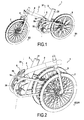
- the figure 1 illustrates a bicycle 1 and in particular the frame 2 of the bicycle.
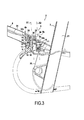
- This frame 2 comprises a rear portion 3 and a front portion 4 hinged together by means of a hinge system 5 configured to allow pivoting along a pivot axis X1 between the rear portion 3 and the front portion 4, so that to allow the positioning of the bicycle in an unfolded position as illustrated in FIG. figure 1 according to which the front part 4 is arranged in the extension of the rear part 3 or, conversely, in a folded position as illustrated in FIG. figure 2 according to which the front part 4 is folded against the rear part 3.
- Figures 1 and 2 the presence of a rear wheel 6 rotatably mounted on the rear portion 3 of the frame 2 and a front wheel 7 mounted in rotation on a fork 8 assembled with the front portion 4 of the frame 2.
- the hinge system 5 comprises a first part 5a provided with a first flat surface 9, arranged on the rear part 3 of the frame 2 and a second part 5b provided with a second flat surface 10, arranged on the front part 4 of the frame 2.
- This first piece 5a and the second piece 5b are mounted in pivot connection relative to each other along the pivot axis X1.
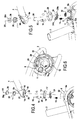
- the first flat surface 9 shows the presence of a bore 11 opening and a groove 12, as illustrated in particular on figures 3 , 5 and 6 .
- a spring 13 is housed in this bore 11.
- this bore 11 slidably receives a pin 14 capable of sliding along a longitudinal axis X2 of the bore.
- pivot axis X1 is perpendicular to the first and second planar surfaces 9,10.
- longitudinal axis X2 is arranged parallel to the pivot axis X1.
- This pin 14 is able to slide inside the bore 11 from a projecting position to a retracted position, and vice versa. In the protruding position, as illustrated on the figure 3 , the pin 14 protrudes from the first flat surface 9. On the contrary, in the retracted position, this pin 14 is disposed below the first flat surface 9, inside the first piece 5a.
- the second part 5b comprises two orifices 15, 16 which open on the second flat surface 10 and which are configured to receive the head 14a of the pin 14 as illustrated in FIG. figure 3 .
- the front portion 4 of the frame 2 is disposed in the front extension of the rear portion 3 of the frame 2, as illustrated in particular on the figure 1 .
- the front portion 4 is pivoted relative to the rear portion 3 and the front wheel 7 is folded against the rear wheel 6, as shown in FIG. figure 2 the head 14a of the pin 14 is disposed in the second orifice 16.
- the first flat surface 9 could be in direct contact with the second flat surface 10 of the front part 4.
- a friction disc 17 is positioned between the first planar surface 9 and the second flat surface 10. This friction disc 17 is immobilized in rotation along the pivot axis X1 with respect to the second surface plane 10 so as to pivot with it when the front portion 4 of the frame 2 is folded against the rear portion 3 of the frame 2 or conversely deployed in the front extension of said rear portion 3 of the frame 2.
- this friction disc 17 also comprises a first orifice 18 which corresponds with the first orifice 15 opening on the second flat surface 10 and a second orifice 19 which corresponds with the second orifice 16 opening on the second flat surface 10, so that to allow the passage of the head 14a of the pin 14.
- the head 14a of the pin 14 is conical in shape as the first hole 15 is also conical.
- This conical shape is also provided on the second orifice 16 of the second flat surface 10. This has the advantage of properly blocking the first part 5a on the rear part 3 with respect to the second part 5b on the front part 4 along the axis X1, without risk of play on the pivot link during the blocking.
- the spring 13 acts on the pin so as to keep it in a normal position protruding from the first surface 9.
- the pin 14 coincides with the first orifice 15 or with the second orifice 16 of the second flat surface 10 , it always penetrates inside one or the other of said orifices 15, 16 so as to ensure the locking between the front portion 4 and the rear portion 3 of the frame 2 in the folded position or in the unfolded position.
- the withdrawal of the head 14a of the pin vis-à-vis the first port 15 or the second port 16 on the second part 5b is ensured by retracting the pin 14 below the first flat surface 9, inside the first room 5a.
- the pin 14 is actuated by means of a traction cable 20 illustrated in particular on the Figures 1 to 3 .
- a traction cable 20 illustrated in particular on the Figures 1 to 3 .
- This cable 20 penetrates inside the seat tube 21.
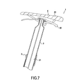
- This cable 20 is preferably actuated by means of a handling handle 22 arranged under the saddle 23 of the bicycle 1, as shown in FIG. figure 7 .
- the groove 12 is circular in shape and allows the reception of a spring 24 illustrated on the Figures 4 and 5 .
- This spring 24 has its first end 24a which is fixed on a stud 25 arranged inside the groove 12 on the first part 5a, as shown in FIG. figure 6 .
- the second end 24b of the spring 24 is assembled with a stud 26 which is embedded in an orifice 27 arranged on the second flat surface 10 so as to be secured to the second part 5b.
- This pad 26 also passes through an orifice 28 arranged on the friction disk 17 as illustrated in FIGS. Figures 4 and 5 , which immobilizes in rotation along the axis of pivoting X1 said friction disk 17 relative to the second flat surface 10.
- this pad 26 is configured to constitute a stop on the edge 12a of the circular groove 12, illustrated in FIG. figure 5 , if the front portion 4 tends to pivot in the wrong direction, that is to say the direction opposite to that of folding, vis-à-vis the rear portion 3.
- This has the advantage of preventing any pivoting of the front portion 4 relative to the rear portion 3 along the pivot axis X1 in the direction opposite to the folding direction of the bicycle 1, beyond a certain limit.
- the spring 24 When the bicycle 1 is in the unfolded position, that is to say that the head 14a of the pin 14 is inserted into the first orifice 15 of the second flat surface 10, the spring 24 is subjected to a tensile force. On the contrary, when the bicycle 1 is in the folded position, that is to say that the head 14a of the pin is disposed in the second hole 16 on the second flat surface 10, the spring 24 is subjected to a compressive force.
- the user actuates the handling handle 22, which allows to unlock the articulation system.
- the articulation system When the user releases the handling handle 22, the articulation system remains in the unlocked position, since the head 14a of the pin 14 is off-axis with respect to the orifices 15, 16 on the second flat surface 10 and the front portion 4 is inclined relative to the rear portion 3, which then allows the user to be able to manipulate the front portion 4 and the rear portion 3 with both hands to rotate them relative to each other.
- the pivot axis pivot connection X1 arranged between the first part 5a on the front part 4 and the second part 5b on the rear part 3 of the frame 2 makes it possible to constitute a duct 30 allowing in particular the passage of cables 31, for example speed actuating cables, brake cables, lighting cables or the like ...
- This conduit 30 opens on the rear part 3 and on the front part 4.
- This pivot connection 29 is implemented by means of a tubular portion 32 which is tightly mounted on a bore 33 illustrated in FIG. figure 6 arranged on the first part 5a, this tubular portion 32 extending above the first flat surface 9, as illustrated in FIGS. figures 3 , 4 and 5 .
- This tubular portion 32 is inserted into a bore 34 arranged on the second piece 5b as illustrated in FIG. the Figures 3 to 5 , this tubular portion 32 being mounted to pivot directly inside the bore 34.
- a rolling bearing or a bearing disposed between said tubular portion 32 and said bore 34 in particular to limit wear between these two parts.
- a clamping collar 35 which bears against the edge 4a of the second part 5b and is tightly mounted on the upper end 32a of the tubular portion 32, as illustrated in FIG. figure 3 .
- This clamp 35 provides the pivot connection and prevents the sliding of the front portion 4 relative to the rear portion 3.
- this upper end 32a of the tubular portion 32 is threaded, as shown in FIG. figure 3 , and receives by screwing a threaded piece 36 provided with a head 36a configured to abut against the clamping collar 35.
- This threaded piece compresses the assembly so as to eliminate assembly games. This makes it possible to block the sliding along the axis of pivoting X1 of the second part 5b with respect to the first part 5a and thus to implement said pivot connection 29.
- a cover will be provided which is clipped on the upper part 4b of the second part 5b so as to conceal the inside of the articulation system 5.
Landscapes
- Engineering & Computer Science (AREA)
- Mechanical Engineering (AREA)
- Motorcycle And Bicycle Frame (AREA)
Applications Claiming Priority (1)
| Application Number | Priority Date | Filing Date | Title |
|---|---|---|---|
| FR1061402A FR2969980B1 (fr) | 2010-12-31 | 2010-12-31 | Bicyclette pliable |
Publications (2)
| Publication Number | Publication Date |
|---|---|
| EP2471702A1 true EP2471702A1 (de) | 2012-07-04 |
| EP2471702B1 EP2471702B1 (de) | 2013-07-24 |
Family
ID=44123243
Family Applications (1)
| Application Number | Title | Priority Date | Filing Date |
|---|---|---|---|
| EP20110193917 Active EP2471702B1 (de) | 2010-12-31 | 2011-12-16 | Klapprad |
Country Status (6)
| Country | Link |
|---|---|
| US (1) | US9039027B2 (de) |
| EP (1) | EP2471702B1 (de) |
| CN (1) | CN102616317B (de) |
| BR (1) | BRPI1105707A2 (de) |
| ES (1) | ES2431626T3 (de) |
| FR (1) | FR2969980B1 (de) |
Cited By (1)
| Publication number | Priority date | Publication date | Assignee | Title |
|---|---|---|---|---|
| USD897242S1 (en) * | 2018-07-16 | 2020-09-29 | Fook Fah Yap | Compact folding electric bicycle |
Families Citing this family (16)
| Publication number | Priority date | Publication date | Assignee | Title |
|---|---|---|---|---|
| DE102011122836B4 (de) * | 2011-10-17 | 2013-07-25 | Karsten Bettin | Kompaktes, zusammenklappbares Fahrrad |
| USD730778S1 (en) * | 2012-10-02 | 2015-06-02 | JAM Vehicles Limited | Bicycle |
| CN105209331B (zh) * | 2012-11-26 | 2018-10-12 | 格林瑞德有限公司 | 可折叠电动踏板车 |
| US9598131B2 (en) | 2012-12-18 | 2017-03-21 | Matthew ZUSY | Articulated two-wheeled vehicles |
| US8882124B2 (en) * | 2013-03-28 | 2014-11-11 | Fook Fah Yap | Foldable bicycle |
| USD739308S1 (en) * | 2013-05-29 | 2015-09-22 | Richard David Barnaby Latham | Bicycle |
| USD739310S1 (en) * | 2013-11-26 | 2015-09-22 | Richard David Barnaby Latham | Tricycle |
| US10150529B2 (en) * | 2014-06-06 | 2018-12-11 | Bignay, Inc. | Vertically folding bicycle with locking mechanism |
| US9457865B2 (en) * | 2015-02-25 | 2016-10-04 | GM Global Technology Operations LLC | Bicycle with motor assisted folding |
| US9580130B2 (en) * | 2015-02-26 | 2017-02-28 | Ford Global Technologies, Llc | Bicycle with detachable head-tube subassembly |
| US9834275B2 (en) | 2015-07-22 | 2017-12-05 | Montague Corporation | Non-overlapping frame folding bike |
| US10112674B2 (en) * | 2016-05-12 | 2018-10-30 | GM Global Technology Operations LLC | Folding system for bicycle steering tube |
| CN107284574A (zh) * | 2017-06-20 | 2017-10-24 | 上海赳赳自行车科技有限公司 | 一种自行车车架 |
| US12054219B2 (en) | 2018-11-02 | 2024-08-06 | Newcycle Inc. | Folding vehicle |
| FR3090764B1 (fr) * | 2018-12-21 | 2022-08-12 | Decathlon Sa | Charnière pour vélo pliant |
| EP4512708A1 (de) * | 2023-08-21 | 2025-02-26 | Shenzhen King Song Intelligence Technology Co., Ltd. | Intelligentes klappfahrrad mit antriebsrad |
Citations (4)
| Publication number | Priority date | Publication date | Assignee | Title |
|---|---|---|---|---|
| WO1999005021A1 (en) * | 1997-07-21 | 1999-02-04 | Urban Solutions B.V. | Foldable bicycle |
| US20020067020A1 (en) * | 2000-12-06 | 2002-06-06 | Wang Ping Tien | Waist-twisting leisure bike |
| US20020167151A1 (en) * | 2001-05-10 | 2002-11-14 | Merida Industry Co., Ltd. | Foldable bicycle |
| US20090058038A1 (en) * | 2007-08-27 | 2009-03-05 | Cannondale Bicycle Corporation | Bicycle frame and drive link case therefore |
Family Cites Families (25)
| Publication number | Priority date | Publication date | Assignee | Title |
|---|---|---|---|---|
| US1584568A (en) * | 1922-02-17 | 1926-05-11 | Clark Charles Haskell | Bicycle and the like |
| US2372024A (en) * | 1943-08-14 | 1945-03-20 | Frank W Schwinn | Folding bicycle frame |
| US2777711A (en) * | 1951-08-28 | 1957-01-15 | Sigeo Kitakami | Portable folding type bicycle |
| GB1557232A (en) * | 1976-05-21 | 1979-12-05 | Lassiere Ltd A | Portable folding bicycle |
| US4219209A (en) * | 1976-07-21 | 1980-08-26 | Haack Frank P | Bicycle with frame articulated to undergo angular movement while being ridden |
| US4113271A (en) * | 1977-03-04 | 1978-09-12 | Arnold Furia | Folding attachment for bicycles |
| US4579360A (en) * | 1983-06-11 | 1986-04-01 | Bridgestone Cycle Co., Ltd. | Foldable bicycle frame |
| US5975551A (en) * | 1997-07-18 | 1999-11-02 | Montague Corporation | Folding frame bicycle |
| NL1009314C2 (nl) * | 1998-06-04 | 1999-12-07 | Urban Solutions B V | Rijwiel voorzien van trapaandrijving, alsmede trapaandrijving. |
| US20030000754A1 (en) * | 2001-06-07 | 2003-01-02 | Daudt Stephen William | Powered lightweight personal transportation vehicle |
| US20030127825A1 (en) * | 2002-01-08 | 2003-07-10 | Ting-Hsing Chen | Folding structure for a bicycle |
| US20030234509A1 (en) * | 2002-06-20 | 2003-12-25 | Ying-Chi Chen | Bicycle folding device |
| GB2394925B (en) * | 2002-11-05 | 2005-06-01 | Mark Andrew Sanders | Folding cycle |
| TWM259748U (en) * | 2004-06-28 | 2005-03-21 | Guo-Ming Huang | Foldable bicycle frame |
| CN1736793A (zh) * | 2004-08-16 | 2006-02-22 | 唐山市蓝剑车业有限公司 | 全折叠减震自行车 |
| JP4660276B2 (ja) * | 2005-05-23 | 2011-03-30 | 一孝 北原 | 自転車用フレーム |
| TWI299028B (en) * | 2006-02-14 | 2008-07-21 | James Chung-Kei Lau | Human powered ground vehicle comprising foldable sections |
| CN1817729B (zh) * | 2006-03-08 | 2010-05-12 | 韩德玮 | 一种折叠自行车 |
| US20080070729A1 (en) * | 2006-05-11 | 2008-03-20 | Fallbrook Technologies Inc. | Continuously variable drivetrain |
| US20080224441A1 (en) * | 2007-03-12 | 2008-09-18 | I-Shyong Lu | Foldable bicycle |
| TWM361466U (en) * | 2009-03-11 | 2009-07-21 | chun-quan Huang | Folding bicycle |
| TWM367137U (en) * | 2009-05-05 | 2009-10-21 | Ming-Han Yeh | Foldable bicycle |
| US20110305502A1 (en) * | 2010-06-10 | 2011-12-15 | Chiu-Hsiang Lo | Positioning switch mechanism for foldable assembly of bicycles |
| US8473130B2 (en) * | 2010-08-17 | 2013-06-25 | Robrady Capital, Llc | Folding bicycle with electric power train assist |
| US8388005B2 (en) * | 2010-09-29 | 2013-03-05 | Lit Motors Corporation | Foldable scooter |
-
2010
- 2010-12-31 FR FR1061402A patent/FR2969980B1/fr active Active
-
2011
- 2011-12-16 ES ES11193917T patent/ES2431626T3/es active Active
- 2011-12-16 EP EP20110193917 patent/EP2471702B1/de active Active
- 2011-12-26 CN CN201110441214.9A patent/CN102616317B/zh active Active
- 2011-12-29 BR BRPI1105707-6A patent/BRPI1105707A2/pt not_active IP Right Cessation
- 2011-12-29 US US13/339,567 patent/US9039027B2/en active Active
Patent Citations (6)
| Publication number | Priority date | Publication date | Assignee | Title |
|---|---|---|---|---|
| WO1999005021A1 (en) * | 1997-07-21 | 1999-02-04 | Urban Solutions B.V. | Foldable bicycle |
| EP0996565A1 (de) | 1997-07-21 | 2000-05-03 | Urban Solutions B.V. | Klappfahrrad |
| US20020067020A1 (en) * | 2000-12-06 | 2002-06-06 | Wang Ping Tien | Waist-twisting leisure bike |
| US20020167151A1 (en) * | 2001-05-10 | 2002-11-14 | Merida Industry Co., Ltd. | Foldable bicycle |
| US20090058038A1 (en) * | 2007-08-27 | 2009-03-05 | Cannondale Bicycle Corporation | Bicycle frame and drive link case therefore |
| EP2077222A2 (de) | 2007-08-27 | 2009-07-08 | Cannondale Bicycle Corporation | Fahrradrahmen und Antriebsverbindungsgehäuse |
Cited By (1)
| Publication number | Priority date | Publication date | Assignee | Title |
|---|---|---|---|---|
| USD897242S1 (en) * | 2018-07-16 | 2020-09-29 | Fook Fah Yap | Compact folding electric bicycle |
Also Published As
| Publication number | Publication date |
|---|---|
| CN102616317B (zh) | 2014-12-03 |
| BRPI1105707A2 (pt) | 2015-07-28 |
| US9039027B2 (en) | 2015-05-26 |
| EP2471702B1 (de) | 2013-07-24 |
| ES2431626T3 (es) | 2013-11-27 |
| CN102616317A (zh) | 2012-08-01 |
| FR2969980A1 (fr) | 2012-07-06 |
| US20120169029A1 (en) | 2012-07-05 |
| FR2969980B1 (fr) | 2013-11-22 |
Similar Documents
| Publication | Publication Date | Title |
|---|---|---|
| EP2471702B1 (de) | Klapprad | |
| EP1644604B1 (de) | Zunge zum verbinden zweier verkleidungen einer flugzeugstruktur | |
| EP3060428B1 (de) | Vorrichtung zum verriegeln eines faltelements für einen fahrzeugsitz in einer bestimmten position | |
| FR2881694A1 (fr) | Mecanisme de guidage en translation avec blocage en position notamment pour des elements ajustables d'un siege de vehicule automobile | |
| FR2806047A1 (fr) | Mecanisme de verrouillage de siege | |
| EP2631044A1 (de) | Schneidenverriegelungsvorrichtung für den ausgeklappten Zustand für Messer mit einklappbarer Schneide | |
| FR3032093A1 (fr) | Perfectionnement pour poignee avec dragonne de baton de ski ou de marche | |
| FR2811273A1 (fr) | Dispositif de liaison d'un siege amovible et a assise basculante avec le plancher d'un vehicule automobile | |
| FR2885329A1 (fr) | Accoudoir a double articulation pour siege de vehicule automobile | |
| FR2968694A1 (fr) | Attache volante | |
| WO2012143474A1 (fr) | Système de connexion pour la fixation d'un dispositif de portage | |
| EP4166436B1 (de) | Scharnier mit einem entriegelungsorgan | |
| FR2867499A1 (fr) | Verrou de couverture de piscine | |
| FR2765532A1 (fr) | Systeme d'articulation d'un element rabattable de siege arriere sur un vehicule automobile | |
| FR3075847A1 (fr) | Verrou et trappe comprenant un tel verrou | |
| FR2898614A1 (fr) | Dispositif de verrouillage et de deverrouillage a l'aide d'une cle d'un tampon ou couvercle sur un cadre | |
| EP4043290B1 (de) | Haltevorrichtung für ein tragbares elektronisches gerät in einem kraftfahrzeug | |
| CH656319A5 (fr) | Fixation de securite pour ski. | |
| FR2843907A1 (fr) | Dispositif d'articulation de la lame d'un couteau pliant | |
| FR3069217A1 (fr) | Boite a gants | |
| FR3072884A1 (fr) | Butee de dispositif de fixation d'une chaussure | |
| FR2908702A1 (fr) | Agencement de porte-recipient pour une tablette de vehicule automobile | |
| FR3022514A1 (fr) | Ensemble d’essuyage d’une vitre de vehicule automobile comportant une tete de montage et un bras d’entrainement | |
| FR2902724A1 (fr) | Agencement d'une tablette dans un caisson, notamment pour un vehicule automobile | |
| EP0925962A1 (de) | Drehbare Mehrzweck-Anhängerdeichsel |
Legal Events
| Date | Code | Title | Description |
|---|---|---|---|
| AK | Designated contracting states |
Kind code of ref document: A1 Designated state(s): AL AT BE BG CH CY CZ DE DK EE ES FI FR GB GR HR HU IE IS IT LI LT LU LV MC MK MT NL NO PL PT RO RS SE SI SK SM TR |
|
| AX | Request for extension of the european patent |
Extension state: BA ME |
|
| PUAI | Public reference made under article 153(3) epc to a published international application that has entered the european phase |
Free format text: ORIGINAL CODE: 0009012 |
|
| GRAP | Despatch of communication of intention to grant a patent |
Free format text: ORIGINAL CODE: EPIDOSNIGR1 |
|
| 17P | Request for examination filed |
Effective date: 20121220 |
|
| RIC1 | Information provided on ipc code assigned before grant |
Ipc: B62K 15/00 20060101AFI20130118BHEP Ipc: B62K 3/02 20060101ALI20130118BHEP |
|
| GRAS | Grant fee paid |
Free format text: ORIGINAL CODE: EPIDOSNIGR3 |
|
| GRAA | (expected) grant |
Free format text: ORIGINAL CODE: 0009210 |
|
| AK | Designated contracting states |
Kind code of ref document: B1 Designated state(s): AL AT BE BG CH CY CZ DE DK EE ES FI FR GB GR HR HU IE IS IT LI LT LU LV MC MK MT NL NO PL PT RO RS SE SI SK SM TR |
|
| REG | Reference to a national code |
Ref country code: GB Ref legal event code: FG4D Free format text: NOT ENGLISH |
|
| REG | Reference to a national code |
Ref country code: CH Ref legal event code: EP |
|
| REG | Reference to a national code |
Ref country code: AT Ref legal event code: REF Ref document number: 623243 Country of ref document: AT Kind code of ref document: T Effective date: 20130815 |
|
| REG | Reference to a national code |
Ref country code: IE Ref legal event code: FG4D Free format text: LANGUAGE OF EP DOCUMENT: FRENCH |
|
| REG | Reference to a national code |
Ref country code: DE Ref legal event code: R096 Ref document number: 602011002445 Country of ref document: DE Effective date: 20130919 |
|
| REG | Reference to a national code |
Ref country code: ES Ref legal event code: FG2A Ref document number: 2431626 Country of ref document: ES Kind code of ref document: T3 Effective date: 20131127 |
|
| REG | Reference to a national code |
Ref country code: AT Ref legal event code: MK05 Ref document number: 623243 Country of ref document: AT Kind code of ref document: T Effective date: 20130724 |
|
| REG | Reference to a national code |
Ref country code: NL Ref legal event code: VDEP Effective date: 20130724 |
|
| REG | Reference to a national code |
Ref country code: LT Ref legal event code: MG4D |
|
| PG25 | Lapsed in a contracting state [announced via postgrant information from national office to epo] |
Ref country code: IS Free format text: LAPSE BECAUSE OF FAILURE TO SUBMIT A TRANSLATION OF THE DESCRIPTION OR TO PAY THE FEE WITHIN THE PRESCRIBED TIME-LIMIT Effective date: 20131124 Ref country code: LT Free format text: LAPSE BECAUSE OF FAILURE TO SUBMIT A TRANSLATION OF THE DESCRIPTION OR TO PAY THE FEE WITHIN THE PRESCRIBED TIME-LIMIT Effective date: 20130724 Ref country code: AT Free format text: LAPSE BECAUSE OF FAILURE TO SUBMIT A TRANSLATION OF THE DESCRIPTION OR TO PAY THE FEE WITHIN THE PRESCRIBED TIME-LIMIT Effective date: 20130724 Ref country code: PT Free format text: LAPSE BECAUSE OF FAILURE TO SUBMIT A TRANSLATION OF THE DESCRIPTION OR TO PAY THE FEE WITHIN THE PRESCRIBED TIME-LIMIT Effective date: 20131125 Ref country code: SE Free format text: LAPSE BECAUSE OF FAILURE TO SUBMIT A TRANSLATION OF THE DESCRIPTION OR TO PAY THE FEE WITHIN THE PRESCRIBED TIME-LIMIT Effective date: 20130724 Ref country code: CY Free format text: LAPSE BECAUSE OF FAILURE TO SUBMIT A TRANSLATION OF THE DESCRIPTION OR TO PAY THE FEE WITHIN THE PRESCRIBED TIME-LIMIT Effective date: 20130904 Ref country code: NO Free format text: LAPSE BECAUSE OF FAILURE TO SUBMIT A TRANSLATION OF THE DESCRIPTION OR TO PAY THE FEE WITHIN THE PRESCRIBED TIME-LIMIT Effective date: 20131024 Ref country code: HR Free format text: LAPSE BECAUSE OF FAILURE TO SUBMIT A TRANSLATION OF THE DESCRIPTION OR TO PAY THE FEE WITHIN THE PRESCRIBED TIME-LIMIT Effective date: 20130724 |
|
| PG25 | Lapsed in a contracting state [announced via postgrant information from national office to epo] |
Ref country code: SI Free format text: LAPSE BECAUSE OF FAILURE TO SUBMIT A TRANSLATION OF THE DESCRIPTION OR TO PAY THE FEE WITHIN THE PRESCRIBED TIME-LIMIT Effective date: 20130724 Ref country code: PL Free format text: LAPSE BECAUSE OF FAILURE TO SUBMIT A TRANSLATION OF THE DESCRIPTION OR TO PAY THE FEE WITHIN THE PRESCRIBED TIME-LIMIT Effective date: 20130724 Ref country code: NL Free format text: LAPSE BECAUSE OF FAILURE TO SUBMIT A TRANSLATION OF THE DESCRIPTION OR TO PAY THE FEE WITHIN THE PRESCRIBED TIME-LIMIT Effective date: 20130724 Ref country code: GR Free format text: LAPSE BECAUSE OF FAILURE TO SUBMIT A TRANSLATION OF THE DESCRIPTION OR TO PAY THE FEE WITHIN THE PRESCRIBED TIME-LIMIT Effective date: 20131025 Ref country code: FI Free format text: LAPSE BECAUSE OF FAILURE TO SUBMIT A TRANSLATION OF THE DESCRIPTION OR TO PAY THE FEE WITHIN THE PRESCRIBED TIME-LIMIT Effective date: 20130724 Ref country code: LV Free format text: LAPSE BECAUSE OF FAILURE TO SUBMIT A TRANSLATION OF THE DESCRIPTION OR TO PAY THE FEE WITHIN THE PRESCRIBED TIME-LIMIT Effective date: 20130724 |
|
| PG25 | Lapsed in a contracting state [announced via postgrant information from national office to epo] |
Ref country code: CY Free format text: LAPSE BECAUSE OF FAILURE TO SUBMIT A TRANSLATION OF THE DESCRIPTION OR TO PAY THE FEE WITHIN THE PRESCRIBED TIME-LIMIT Effective date: 20130724 |
|
| PG25 | Lapsed in a contracting state [announced via postgrant information from national office to epo] |
Ref country code: RO Free format text: LAPSE BECAUSE OF FAILURE TO SUBMIT A TRANSLATION OF THE DESCRIPTION OR TO PAY THE FEE WITHIN THE PRESCRIBED TIME-LIMIT Effective date: 20130724 Ref country code: DK Free format text: LAPSE BECAUSE OF FAILURE TO SUBMIT A TRANSLATION OF THE DESCRIPTION OR TO PAY THE FEE WITHIN THE PRESCRIBED TIME-LIMIT Effective date: 20130724 Ref country code: EE Free format text: LAPSE BECAUSE OF FAILURE TO SUBMIT A TRANSLATION OF THE DESCRIPTION OR TO PAY THE FEE WITHIN THE PRESCRIBED TIME-LIMIT Effective date: 20130724 Ref country code: SK Free format text: LAPSE BECAUSE OF FAILURE TO SUBMIT A TRANSLATION OF THE DESCRIPTION OR TO PAY THE FEE WITHIN THE PRESCRIBED TIME-LIMIT Effective date: 20130724 Ref country code: CZ Free format text: LAPSE BECAUSE OF FAILURE TO SUBMIT A TRANSLATION OF THE DESCRIPTION OR TO PAY THE FEE WITHIN THE PRESCRIBED TIME-LIMIT Effective date: 20130724 |
|
| PLBE | No opposition filed within time limit |
Free format text: ORIGINAL CODE: 0009261 |
|
| STAA | Information on the status of an ep patent application or granted ep patent |
Free format text: STATUS: NO OPPOSITION FILED WITHIN TIME LIMIT |
|
| BERE | Be: lapsed |
Owner name: DECATHLON Effective date: 20131231 |
|
| 26N | No opposition filed |
Effective date: 20140425 |
|
| REG | Reference to a national code |
Ref country code: DE Ref legal event code: R097 Ref document number: 602011002445 Country of ref document: DE Effective date: 20140425 |
|
| PG25 | Lapsed in a contracting state [announced via postgrant information from national office to epo] |
Ref country code: LU Free format text: LAPSE BECAUSE OF FAILURE TO SUBMIT A TRANSLATION OF THE DESCRIPTION OR TO PAY THE FEE WITHIN THE PRESCRIBED TIME-LIMIT Effective date: 20131216 |
|
| REG | Reference to a national code |
Ref country code: IE Ref legal event code: MM4A |
|
| PG25 | Lapsed in a contracting state [announced via postgrant information from national office to epo] |
Ref country code: IE Free format text: LAPSE BECAUSE OF NON-PAYMENT OF DUE FEES Effective date: 20131216 Ref country code: BE Free format text: LAPSE BECAUSE OF NON-PAYMENT OF DUE FEES Effective date: 20131231 |
|
| PG25 | Lapsed in a contracting state [announced via postgrant information from national office to epo] |
Ref country code: MC Free format text: LAPSE BECAUSE OF FAILURE TO SUBMIT A TRANSLATION OF THE DESCRIPTION OR TO PAY THE FEE WITHIN THE PRESCRIBED TIME-LIMIT Effective date: 20130724 |
|
| PG25 | Lapsed in a contracting state [announced via postgrant information from national office to epo] |
Ref country code: SM Free format text: LAPSE BECAUSE OF FAILURE TO SUBMIT A TRANSLATION OF THE DESCRIPTION OR TO PAY THE FEE WITHIN THE PRESCRIBED TIME-LIMIT Effective date: 20130724 |
|
| PG25 | Lapsed in a contracting state [announced via postgrant information from national office to epo] |
Ref country code: MK Free format text: LAPSE BECAUSE OF FAILURE TO SUBMIT A TRANSLATION OF THE DESCRIPTION OR TO PAY THE FEE WITHIN THE PRESCRIBED TIME-LIMIT Effective date: 20130724 Ref country code: RS Free format text: LAPSE BECAUSE OF FAILURE TO SUBMIT A TRANSLATION OF THE DESCRIPTION OR TO PAY THE FEE WITHIN THE PRESCRIBED TIME-LIMIT Effective date: 20131024 Ref country code: BG Free format text: LAPSE BECAUSE OF FAILURE TO SUBMIT A TRANSLATION OF THE DESCRIPTION OR TO PAY THE FEE WITHIN THE PRESCRIBED TIME-LIMIT Effective date: 20130724 Ref country code: HU Free format text: LAPSE BECAUSE OF FAILURE TO SUBMIT A TRANSLATION OF THE DESCRIPTION OR TO PAY THE FEE WITHIN THE PRESCRIBED TIME-LIMIT; INVALID AB INITIO Effective date: 20111216 |
|
| REG | Reference to a national code |
Ref country code: CH Ref legal event code: PL |
|
| PG25 | Lapsed in a contracting state [announced via postgrant information from national office to epo] |
Ref country code: MT Free format text: LAPSE BECAUSE OF FAILURE TO SUBMIT A TRANSLATION OF THE DESCRIPTION OR TO PAY THE FEE WITHIN THE PRESCRIBED TIME-LIMIT Effective date: 20130724 |
|
| PG25 | Lapsed in a contracting state [announced via postgrant information from national office to epo] |
Ref country code: LI Free format text: LAPSE BECAUSE OF NON-PAYMENT OF DUE FEES Effective date: 20141231 Ref country code: CH Free format text: LAPSE BECAUSE OF NON-PAYMENT OF DUE FEES Effective date: 20141231 |
|
| REG | Reference to a national code |
Ref country code: FR Ref legal event code: PLFP Year of fee payment: 5 |
|
| PG25 | Lapsed in a contracting state [announced via postgrant information from national office to epo] |
Ref country code: TR Free format text: LAPSE BECAUSE OF FAILURE TO SUBMIT A TRANSLATION OF THE DESCRIPTION OR TO PAY THE FEE WITHIN THE PRESCRIBED TIME-LIMIT Effective date: 20130724 |
|
| GBPC | Gb: european patent ceased through non-payment of renewal fee |
Effective date: 20151216 |
|
| PG25 | Lapsed in a contracting state [announced via postgrant information from national office to epo] |
Ref country code: GB Free format text: LAPSE BECAUSE OF NON-PAYMENT OF DUE FEES Effective date: 20151216 |
|
| REG | Reference to a national code |
Ref country code: FR Ref legal event code: PLFP Year of fee payment: 6 |
|
| REG | Reference to a national code |
Ref country code: FR Ref legal event code: PLFP Year of fee payment: 7 |
|
| PG25 | Lapsed in a contracting state [announced via postgrant information from national office to epo] |
Ref country code: AL Free format text: LAPSE BECAUSE OF FAILURE TO SUBMIT A TRANSLATION OF THE DESCRIPTION OR TO PAY THE FEE WITHIN THE PRESCRIBED TIME-LIMIT Effective date: 20130724 |
|
| REG | Reference to a national code |
Ref country code: DE Ref legal event code: R082 Ref document number: 602011002445 Country of ref document: DE Representative=s name: CBDL PATENTANWAELTE GBR, DE Ref country code: DE Ref legal event code: R082 Ref document number: 602011002445 Country of ref document: DE Representative=s name: CBDL PATENTANWAELTE EGBR, DE |
|
| P01 | Opt-out of the competence of the unified patent court (upc) registered |
Effective date: 20230605 |
|
| PGFP | Annual fee paid to national office [announced via postgrant information from national office to epo] |
Ref country code: DE Payment date: 20241211 Year of fee payment: 14 |
|
| PGFP | Annual fee paid to national office [announced via postgrant information from national office to epo] |
Ref country code: ES Payment date: 20250107 Year of fee payment: 14 |
|
| PGFP | Annual fee paid to national office [announced via postgrant information from national office to epo] |
Ref country code: IT Payment date: 20251209 Year of fee payment: 15 |
|
| PGFP | Annual fee paid to national office [announced via postgrant information from national office to epo] |
Ref country code: FR Payment date: 20251218 Year of fee payment: 15 |