EP2470404B1 - Hydrodynamische maschine, insbesondere hydrodynamischer retarder - Google Patents
Hydrodynamische maschine, insbesondere hydrodynamischer retarder Download PDFInfo
- Publication number
- EP2470404B1 EP2470404B1 EP10798959.2A EP10798959A EP2470404B1 EP 2470404 B1 EP2470404 B1 EP 2470404B1 EP 10798959 A EP10798959 A EP 10798959A EP 2470404 B1 EP2470404 B1 EP 2470404B1
- Authority
- EP
- European Patent Office
- Prior art keywords
- sealing
- sliding ring
- hydrodynamic
- hydrodynamic machine
- insert
- Prior art date
- Legal status (The legal status is an assumption and is not a legal conclusion. Google has not performed a legal analysis and makes no representation as to the accuracy of the status listed.)
- Active
Links
- 238000007789 sealing Methods 0.000 claims description 52
- 239000007788 liquid Substances 0.000 claims description 34
- 238000001816 cooling Methods 0.000 claims description 7
- 230000013011 mating Effects 0.000 claims description 7
- 230000001050 lubricating effect Effects 0.000 claims 2
- 230000004888 barrier function Effects 0.000 description 43
- 239000012530 fluid Substances 0.000 description 33
- XLYOFNOQVPJJNP-UHFFFAOYSA-N water Substances O XLYOFNOQVPJJNP-UHFFFAOYSA-N 0.000 description 12
- 230000000903 blocking effect Effects 0.000 description 3
- 239000000203 mixture Substances 0.000 description 3
- 241001295925 Gegenes Species 0.000 description 2
- 239000002826 coolant Substances 0.000 description 2
- 230000008878 coupling Effects 0.000 description 2
- 238000010168 coupling process Methods 0.000 description 2
- 238000005859 coupling reaction Methods 0.000 description 2
- 238000004146 energy storage Methods 0.000 description 2
- 230000004323 axial length Effects 0.000 description 1
- 230000001419 dependent effect Effects 0.000 description 1
- 230000002349 favourable effect Effects 0.000 description 1
- 230000010354 integration Effects 0.000 description 1
- 230000002035 prolonged effect Effects 0.000 description 1
- 239000007787 solid Substances 0.000 description 1
Images

Classifications
-
- F—MECHANICAL ENGINEERING; LIGHTING; HEATING; WEAPONS; BLASTING
- F16—ENGINEERING ELEMENTS AND UNITS; GENERAL MEASURES FOR PRODUCING AND MAINTAINING EFFECTIVE FUNCTIONING OF MACHINES OR INSTALLATIONS; THERMAL INSULATION IN GENERAL
- F16J—PISTONS; CYLINDERS; SEALINGS
- F16J15/00—Sealings
- F16J15/16—Sealings between relatively-moving surfaces
- F16J15/34—Sealings between relatively-moving surfaces with slip-ring pressed against a more or less radial face on one member
- F16J15/3404—Sealings between relatively-moving surfaces with slip-ring pressed against a more or less radial face on one member and characterised by parts or details relating to lubrication, cooling or venting of the seal
-
- B—PERFORMING OPERATIONS; TRANSPORTING
- B60—VEHICLES IN GENERAL
- B60T—VEHICLE BRAKE CONTROL SYSTEMS OR PARTS THEREOF; BRAKE CONTROL SYSTEMS OR PARTS THEREOF, IN GENERAL; ARRANGEMENT OF BRAKING ELEMENTS ON VEHICLES IN GENERAL; PORTABLE DEVICES FOR PREVENTING UNWANTED MOVEMENT OF VEHICLES; VEHICLE MODIFICATIONS TO FACILITATE COOLING OF BRAKES
- B60T10/00—Control or regulation for continuous braking making use of fluid or powdered medium, e.g. for use when descending a long slope
- B60T10/02—Control or regulation for continuous braking making use of fluid or powdered medium, e.g. for use when descending a long slope with hydrodynamic brake
-
- F—MECHANICAL ENGINEERING; LIGHTING; HEATING; WEAPONS; BLASTING
- F16—ENGINEERING ELEMENTS AND UNITS; GENERAL MEASURES FOR PRODUCING AND MAINTAINING EFFECTIVE FUNCTIONING OF MACHINES OR INSTALLATIONS; THERMAL INSULATION IN GENERAL
- F16J—PISTONS; CYLINDERS; SEALINGS
- F16J15/00—Sealings
- F16J15/16—Sealings between relatively-moving surfaces
- F16J15/34—Sealings between relatively-moving surfaces with slip-ring pressed against a more or less radial face on one member
- F16J15/3404—Sealings between relatively-moving surfaces with slip-ring pressed against a more or less radial face on one member and characterised by parts or details relating to lubrication, cooling or venting of the seal
- F16J15/3408—Sealings between relatively-moving surfaces with slip-ring pressed against a more or less radial face on one member and characterised by parts or details relating to lubrication, cooling or venting of the seal at least one ring having an uneven slipping surface
- F16J15/3412—Sealings between relatively-moving surfaces with slip-ring pressed against a more or less radial face on one member and characterised by parts or details relating to lubrication, cooling or venting of the seal at least one ring having an uneven slipping surface with cavities
- F16J15/342—Sealings between relatively-moving surfaces with slip-ring pressed against a more or less radial face on one member and characterised by parts or details relating to lubrication, cooling or venting of the seal at least one ring having an uneven slipping surface with cavities with means for feeding fluid directly to the face
Definitions
- the present invention relates to a hydrodynamic machine, in particular a hydrodynamic retarder, in detail according to the preamble of claim 1.
- Hydrodynamic machines have been known for many decades. They have at least two paddle wheels, of which at least one rotates. At least one second impeller forms with the first impeller from a working space which is either permanently filled with working fluid or optionally filled with working fluid to transmit torque or drive power hydrodynamically from the first impeller to the second impeller.
- the hydrodynamic machine is a hydrodynamic retarder whose first impeller is hydrodynamically braked.
- the hydrodynamic machine is a hydrodynamic converter.
- the present invention is basically applicable to all of the aforementioned hydrodynamic machine designs.
- the present invention has for its object to provide a hydrodynamic machine, in particular a hydrodynamic retarder whose drive shaft is particularly reliable and permanently sealed against the housing of the hydrodynamic machine to avoid unwanted leakage of working fluid from the hydrodynamic machine.
- Under Drive shaft is to understand any form of a wave, whether hollow shaft or solid shaft or disc or annular shaft, which allows a drive at least one paddle wheel of the hydrodynamic machine.
- the hydrodynamic machine according to the invention which is designed in particular as a hydrodynamic retarder, has at least a first revolving impeller and a second impeller, which also rotates or is held stationary (not revolving). Both paddle wheels form a work space that can be filled or filled with a working medium, which in particular has a toroidal shape in order to transmit torque hydrodynamically from the first paddle wheel to the second paddle wheel. If the second blade wheel is held stationary or driven counter to the direction of rotation of the first blade wheel, the hydrodynamic machine operates as a retarder or as Gegenlaufretarder. If the second impeller is rotatably mounted to be driven hydrodynamically via the working medium circuit in the working space of the first impeller, the hydrodynamic machine operates as a hydrodynamic coupling.
- the hydrodynamic machine according to the invention also has at least one housing which either encloses the other paddle wheel together with one of the two paddle wheels, whereby the housing is at least partially formed by one of the two paddle wheels, namely the "outer" paddle wheel, or both paddle wheels encloses. If the housing encloses both paddle wheels, this may in particular be kept stationary. Likewise, when the housing together with a stator, which is formed by one of the two paddle wheels, the other paddle wheel encloses.
- the mechanical seal has at least one barrier fluid supply to supply a barrier fluid of the mechanical seal and to cool and / or lubricate by means of this sealing liquid, the mechanical seal.
- the mechanical seal has at least one first sliding ring and a second sliding ring, which are arranged concentrically enclosing in the radial direction and each having a sealing surface, which seal a radial direction to the drive shaft extending sealing gap together with a counter element.
- the second mechanical seal is arranged on a larger diameter than the first mechanical seal and encloses this advantageous on the outside completely.
- the mechanical seals can be positioned on the same axial section, so that in particular their sealing surfaces are aligned. This will be shown below with reference to the figures.
- a barrier fluid channel to cool the two sealing surfaces with barrier fluid and / or lubricate.
- the barrier fluid channel is charged with barrier fluid from the barrier fluid supply, so that the barrier fluid can flow through this barrier fluid channel, and can get over the mouth of the barrier fluid channel to the two sealing surfaces.
- a barrier liquid discharge is provided, in which the barrier liquid, after having cooled and / or lubricated the two sealing surfaces, flows in and is then discharged via the barrier liquid discharge from the mechanical seal and in particular from the hydrodynamic machine.
- first slide ring and the second slide ring are made in one piece or mechanically connected to each other.
- first sliding ring and the second sliding ring are designed as separate components, which are thus not mechanically connected to each other.
- either the two sliding rings, in particular together with the same speed, with the drive shaft and / or a paddle wheel, and the counter-element is stationary.
- the counter element runs around with the drive shaft and / or a paddle wheel in particular at the same speed, and the two slip rings are held stationary.
- the two sealing surfaces seal the sealing gap together with a common one-piece counter-element, which is designed in particular as a counter ring from.
- an at least partially axially extending guide element in particular in the form of an insert, is provided at least in the mouth of the barrier liquid channel in the direction of at least the radially inner sealing surface or in the direction of both sealing surfaces passes from the barrier liquid channel exiting barrier liquid.
- the guide element is advantageously designed as a, in particular in an axial section through the hydrodynamic machine L-shaped insert, which is arranged in the radial direction between the first seal ring and the second seal ring.
- the insert advantageously separates the barrier fluid supply from a barrier fluid removal of the mechanical seal, and is advantageously arranged extending within the barrier fluid channel that the barrier fluid from the barrier fluid supply along the insert, in particular in the axial direction, in the region of the first radially inner sealing surface, then around the Insert around radially outward in the area of second radially outer sealing surface and then, in particular again in the axial direction, flows into the barrier liquid discharge.
- the barrier fluid from the barrier fluid supply flows particularly advantageously firstly in a first axial direction along the insert and then, after having cooled and / or lubricated the sealing surfaces, along a second, opposite axial direction in the direction of the barrier fluid discharge.
- the barrier fluid supply and the barrier fluid discharge can each be designed as at least partially extending in the radial direction channel, the two channels in the circumferential direction offset from one another, in particular by substantially or exactly 180 ° offset, can be arranged.
- the mechanical seal has a housing which encloses the two sliding rings and in particular the counter-element.
- a bore can then be provided as a barrier liquid supply and a further bore as a barrier liquid discharge, which can be connected to the holes corresponding channels in the housing and / or in a paddle wheel of the hydrodynamic machine.
- a spring such as wave spring or sinusoidal spring is used, which acts on the two seal rings in the direction of the sealing surfaces with spring force to press the seal rings with their sealing surfaces against the counter element.
- the spring is inserted between a corresponding housing wall and the two sliding rings, wherein one of the two sliding rings, in particular the radially outer slide ring, is pressurized by the spring via the insert.
- the insert can rest freely on the sealing ring, in particular in the axial direction.
- Each sliding ring can be provided with a separate spring.
- one, in particular a single spring acts on several or all sliding rings.
- FIG. 1 schematically a hydrodynamic retarder is shown, wherein schematically a section is shown only by one side of the drive shaft 5. The other side is designed accordingly mirror image (not shown).
- Both blade wheels 1, 2 together form a toroidal working space 3, in which either a working fluid, such as oil, water or a water mixture can be introduced to drive power, here braking torque, hydrodynamic from first impeller 1 to the second impeller 2 to transmit the stator.
- a working fluid such as oil, water or a water mixture
- the second impeller 2 forms a housing 4 together with a shell surrounding the first impeller 1 on the side facing away from the second impeller 2.
- the first impeller 1 is driven via the drive shaft 5.
- the drive shaft 5 is by means of a number of seals against the housing 4th sealed.
- the far right in the FIG. 1 Seal shown can be provided as designed according to the invention 6 mechanical seal.
- the FIG. 1 provide shown number of seals.
- one of the other seals represented by way of example could also be designed as a mechanical seal according to the invention.
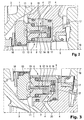
- FIG. 2 now an axial section through a corresponding mechanical seal 6 is shown. It also recognizes the radially inner region of the first blade wheel 1 and the drive shaft 5 and a radially inner part of the housing 4. Also, a radially inner part of the working space 3 can still be seen.
- FIG. 3 is a corresponding section, but shown in an offset in the circumferential direction of the hydrodynamic retarder cutting plane.
- Corresponding elements are numbered by the same reference numerals.
- the mechanical seal 6 has a housing 16 which encloses and guides the two seal rings 8, 9. Between an end wall of the housing 16 and the two sliding rings 8, 9, two springs 17, each arranged in the form of a sinusoidal spring or wave spring, which are supported against the housing 16 and the slip rings 8, 9 with their sealing surfaces 10, 11 against the mating ring Press 13 to achieve the best possible sealing of the sealing gap.
- the two Springs 17 surround each other concentrically. Alternatively, a common spring could be provided, which acts on both slip rings 8, 9.
- the counter-ring 13 is also pressurized by a spring, here designated 18, in the direction of the seal rings 8, 9.
- a spring here designated 18, in the direction of the seal rings 8, 9.
- the housing 16 is inserted together with the two sliding rings 8, 9 in the housing 4 of the hydrodynamic retarder and therefore does not run around.
- the counter ring 13 is inserted into the drive shaft 5 and therefore runs together with the drive shaft 5 and the first blade wheel 1 order.
- an insert 14 is introduced, which, as will be explained below, has a flow guidance function for the introduced into the mechanical seal 6 and funded to the sealing gap barrier liquid.
- the insert 14 has an L-shape in the section shown, wherein the comparatively longer leg is parallel to the axis of rotation 19 of the drive shaft 5 and the comparatively shorter leg perpendicular thereto.
- the comparatively shorter leg is introduced between the second slide ring 9 and the radially outer spring 17 such that the spring 17 exerts its pressure force on the insert 14 on the second slide ring 9, whereas in the embodiment shown, the radially inner spring 17 on their pressure force the first slide ring 8 directly exerts without the interposition of another element.
- the barrier liquid is fed via a supply channel 20 in the housing 4 of the hydrodynamic retarder to a barrier fluid supply 7 of the Passed mechanical seal 6.
- the blocking fluid supply 7 can be embodied, for example, in the form of one or more bores in the housing 16 of the mechanical seal 6, wherein the at least one bore preferably extends at least partially in the radial direction.
- the barrier liquid From the barrier fluid supply 7, the barrier liquid, as indicated by the arrows, enters the radially inner gap between the insert 14 and the first seal ring 8, flows in this gap in the axial direction along the comparatively longer leg of the insert 14 to the free leg end of the Insert 14, which is positioned near the sealing surfaces 10, 11. There, the barrier liquid flows radially outwardly around the free end of the insert 14 into the radially outer gap between the insert 14 and the second, radially outer seal ring 9. Due to this flow, the barrier liquid is forced to close close to the sealing surfaces 10, 11, to lubricate and / or cool them.
- the heat absorbed is dissipated by the outflowing barrier liquid, the barrier liquid again in the axial direction, this time opposite to the "way" through the gap between the insert 14 and the second seal ring 9 to the barrier liquid discharge 15 of the convection seal 6 flows.
- the barrier liquid discharge 15 is in turn designed in the form of one or more holes in the housing 16 of the mechanical seal 6, wherein in this case aligned bores for forming the barrier liquid discharge 15 are also provided in the second seal ring 9.
- the barrier liquid then flows through a discharge channel 21 or a plurality thereof in the housing 4 of the hydrodynamic retarder.
- the illustrated embodiment of the mechanical seal 6 allows extremely efficient cooling of the two sealing surfaces 10, 11 with simultaneous optimal sealing of the drive shaft 5 relative to the housing 4 of the hydrodynamic retarder. Nested by the radial-nested Arrangement can also be achieved a very short axial length and a very compact embodiment of the mechanical seal 6 with a uniform application of force to both sliding rings 8, 9. Furthermore, the number of components of the mechanical seal 6 is minimized.
- the blocking fluid supply 7 or the supply channel 20 can be connected, for example, to the working fluid supply of the hydrodynamic machine, in this case the hydrodynamic retarder, in order to achieve the highest possible pressure.
- the blocking liquid discharge 15 or the removal channel 21 can be connected, for example, to the suction side of a pump (not shown) by means of which the working medium is pumped through the working space 3 or into the retardant inlet.
- the pump will usually be the coolant pump.
Landscapes
- Engineering & Computer Science (AREA)
- General Engineering & Computer Science (AREA)
- Mechanical Engineering (AREA)
- Physics & Mathematics (AREA)
- Fluid Mechanics (AREA)
- Transportation (AREA)
- Transmission Of Braking Force In Braking Systems (AREA)
- Braking Arrangements (AREA)
Applications Claiming Priority (2)
| Application Number | Priority Date | Filing Date | Title |
|---|---|---|---|
| DE102009058341A DE102009058341A1 (de) | 2009-12-15 | 2009-12-15 | Hydrodynamische Maschine, insbesondere hydrodynamischer Retarder |
| PCT/EP2010/007525 WO2011082759A1 (de) | 2009-12-15 | 2010-12-10 | Hydrodynamische maschine, insbesondere hydrodynamischer retarder |
Publications (2)
| Publication Number | Publication Date |
|---|---|
| EP2470404A1 EP2470404A1 (de) | 2012-07-04 |
| EP2470404B1 true EP2470404B1 (de) | 2013-05-29 |
Family
ID=43708968
Family Applications (1)
| Application Number | Title | Priority Date | Filing Date |
|---|---|---|---|
| EP10798959.2A Active EP2470404B1 (de) | 2009-12-15 | 2010-12-10 | Hydrodynamische maschine, insbesondere hydrodynamischer retarder |
Country Status (5)
| Country | Link |
|---|---|
| EP (1) | EP2470404B1 (enExample) |
| CN (1) | CN102892649A (enExample) |
| DE (1) | DE102009058341A1 (enExample) |
| IN (1) | IN2012DN03264A (enExample) |
| WO (1) | WO2011082759A1 (enExample) |
Families Citing this family (5)
| Publication number | Priority date | Publication date | Assignee | Title |
|---|---|---|---|---|
| SE540190C2 (en) * | 2015-04-30 | 2018-04-24 | Scania Cv Ab | A sealing arrangement for a hydrodynamic machine |
| DE102017213148B4 (de) * | 2017-07-31 | 2020-01-23 | Carl Freudenberg Kg | Gleitringdichtungsanordnung eines hydrodynamischen Retarders sowie hydrodynamischer Retarder |
| SE543132C2 (en) * | 2018-04-25 | 2020-10-13 | Scania Cv Ab | Sealing Arrangement, Hydrodynamic Machine, and Vehicle |
| DE102018120039B3 (de) * | 2018-08-17 | 2020-01-23 | Carl Freudenberg Kg | Gleitringdichtung |
| DE102020125509B3 (de) | 2020-09-30 | 2022-02-24 | Voith Patent Gmbh | Bremssystem zur Koppelung mit einem Antriebsstrang |
Family Cites Families (12)
| Publication number | Priority date | Publication date | Assignee | Title |
|---|---|---|---|---|
| NL299260A (enExample) * | 1962-10-17 | |||
| GB980810A (en) * | 1963-01-28 | 1965-01-20 | Dowty Fuel Syst Ltd | Apparatus including a shaft rotatably mounted in a housing and sealing means therefor |
| DE1600523C3 (de) * | 1967-06-03 | 1974-08-01 | Sealol Inc., Warwick, R.I. (V.St.A.) | Gleitringdichtung mit einer dem Radial sich erstreckenden Dichtungsspalt zugeführten Sperrflüssigkeit |
| FR1564628A (enExample) * | 1968-02-05 | 1969-04-25 | ||
| CH616994A5 (en) * | 1977-05-02 | 1980-04-30 | Asbest & Packungs Ag | Mechanical seal |
| CH626950A5 (enExample) * | 1978-04-07 | 1981-12-15 | Maag Zahnraeder & Maschinen Ag | |
| EP0070335A1 (en) * | 1981-07-17 | 1983-01-26 | Gits Bros. Mfg. Co. | Pressure compensated shaft seal |
| US4900039A (en) * | 1988-07-27 | 1990-02-13 | The Pullman Company | Twin face seal |
| US5820129A (en) * | 1996-07-11 | 1998-10-13 | Power Packing Co., Inc. | Mechanical split double seals |
| DE10242736A1 (de) | 2002-09-13 | 2004-03-18 | Voith Turbo Gmbh & Co. Kg | Antriebseinheit mit einem Retarder |
| DE102005009456A1 (de) | 2005-03-02 | 2006-09-07 | Voith Turbo Gmbh & Co. Kg | Retarder-Rotationspumpen-Baugruppe |
| DE102006054615B3 (de) | 2006-11-17 | 2007-12-20 | Voith Patent Gmbh | Kühlsystem mit einem Antriebsmotor und einer hydrodynamischen Maschine |
-
2009
- 2009-12-15 DE DE102009058341A patent/DE102009058341A1/de not_active Withdrawn
-
2010
- 2010-12-10 IN IN3264DEN2012 patent/IN2012DN03264A/en unknown
- 2010-12-10 EP EP10798959.2A patent/EP2470404B1/de active Active
- 2010-12-10 WO PCT/EP2010/007525 patent/WO2011082759A1/de not_active Ceased
- 2010-12-10 CN CN201080051704.1A patent/CN102892649A/zh active Pending
Also Published As
| Publication number | Publication date |
|---|---|
| IN2012DN03264A (enExample) | 2015-10-23 |
| DE102009058341A1 (de) | 2011-06-16 |
| EP2470404A1 (de) | 2012-07-04 |
| WO2011082759A1 (de) | 2011-07-14 |
| CN102892649A (zh) | 2013-01-23 |
Similar Documents
| Publication | Publication Date | Title |
|---|---|---|
| EP2006564B1 (de) | Hydrodynamische Maschine | |
| EP2470404B1 (de) | Hydrodynamische maschine, insbesondere hydrodynamischer retarder | |
| EP3301787B1 (de) | Elektrische maschine mit kühlsystem | |
| EP2816226A1 (de) | Windkraftanlage mit einem Gleitlager | |
| DE69819293T2 (de) | Hydraulikdichtung | |
| DE602005003199T2 (de) | Verbesserung eines Turbinenstarters durch den Einsatz einer Spieldichtung | |
| DE102016121241B4 (de) | Hydraulischer Antrieb, hydraulischer Motor und integrierte Pumpe mit dem hydraulischen Antrieb | |
| EP2322803B1 (de) | Pumpe mit einer magnetkupplung | |
| DE102006021331A1 (de) | Hydrodynamische Maschine | |
| EP2707629B1 (de) | Vorrichtung zum abdichten eines pumpraums einer drehkolbenpumpe, sowie drehkolbenpumpe mit selbiger | |
| DE102007060764A1 (de) | Hydrodynamische Maschine, insbesondere hydrodynamischer Retarder | |
| DE102013208454A1 (de) | Hydrostatische Axialkolbenmaschine mit einer Zylindertrommel mit schräg zu deren Axialrichtung gelagerten Arbeitskolben und einem ebenen Steuerspiegel | |
| DE10360056A1 (de) | Hydrodynamische Kupplung | |
| EP1761422A1 (de) | Retarder-rotationspumpen-baugruppe | |
| EP2535621B1 (de) | Wellendichtungsring für ein Sperröldichtungssystem eines wasserstoffgekühlten Generators | |
| DE10360055A1 (de) | Hydrodynamische Kupplung | |
| DE202014006626U1 (de) | Hydrodynamische Kupplung | |
| DE102007030199A1 (de) | Getriebe für eine Schraubenspindelpumpe | |
| EP3019763B1 (de) | Hydrodynamische maschine, insbesondere hydrodynamische kupplung | |
| DE102005056468B4 (de) | Hydrodynamische Maschine | |
| DE202014006629U1 (de) | Hydrodynamische Kupplung | |
| EP3611407B1 (de) | Gleitringdichtung | |
| DE2010403C3 (de) | Einrichtung zur Zu- und Abfuhrung einer Kühlflüssigkeit fur mindestens einen in dem Rotor einer elektrischen Maschine angeordneten Kuhlkanal | |
| DE202005003329U1 (de) | Retarder-Rotationspumpen-Baugruppe | |
| DE102023115238A1 (de) | Anordnung mit einem ölführenden Übergangsbereich zwischen einem feststehenden Bauteil und einem rotierend gelagerten Teil |
Legal Events
| Date | Code | Title | Description |
|---|---|---|---|
| PUAI | Public reference made under article 153(3) epc to a published international application that has entered the european phase |
Free format text: ORIGINAL CODE: 0009012 |
|
| 17P | Request for examination filed |
Effective date: 20120331 |
|
| AK | Designated contracting states |
Kind code of ref document: A1 Designated state(s): AL AT BE BG CH CY CZ DE DK EE ES FI FR GB GR HR HU IE IS IT LI LT LU LV MC MK MT NL NO PL PT RO RS SE SI SK SM TR |
|
| GRAP | Despatch of communication of intention to grant a patent |
Free format text: ORIGINAL CODE: EPIDOSNIGR1 |
|
| DAX | Request for extension of the european patent (deleted) | ||
| GRAS | Grant fee paid |
Free format text: ORIGINAL CODE: EPIDOSNIGR3 |
|
| GRAA | (expected) grant |
Free format text: ORIGINAL CODE: 0009210 |
|
| AK | Designated contracting states |
Kind code of ref document: B1 Designated state(s): AL AT BE BG CH CY CZ DE DK EE ES FI FR GB GR HR HU IE IS IT LI LT LU LV MC MK MT NL NO PL PT RO RS SE SI SK SM TR |
|
| REG | Reference to a national code |
Ref country code: GB Ref legal event code: FG4D Free format text: NOT ENGLISH |
|
| REG | Reference to a national code |
Ref country code: CH Ref legal event code: EP |
|
| REG | Reference to a national code |
Ref country code: AT Ref legal event code: REF Ref document number: 614183 Country of ref document: AT Kind code of ref document: T Effective date: 20130615 |
|
| REG | Reference to a national code |
Ref country code: IE Ref legal event code: FG4D Free format text: LANGUAGE OF EP DOCUMENT: GERMAN |
|
| REG | Reference to a national code |
Ref country code: DE Ref legal event code: R096 Ref document number: 502010003494 Country of ref document: DE Effective date: 20130725 |
|
| REG | Reference to a national code |
Ref country code: LT Ref legal event code: MG4D |
|
| PG25 | Lapsed in a contracting state [announced via postgrant information from national office to epo] |
Ref country code: PT Free format text: LAPSE BECAUSE OF FAILURE TO SUBMIT A TRANSLATION OF THE DESCRIPTION OR TO PAY THE FEE WITHIN THE PRESCRIBED TIME-LIMIT Effective date: 20130930 Ref country code: IS Free format text: LAPSE BECAUSE OF FAILURE TO SUBMIT A TRANSLATION OF THE DESCRIPTION OR TO PAY THE FEE WITHIN THE PRESCRIBED TIME-LIMIT Effective date: 20130929 Ref country code: ES Free format text: LAPSE BECAUSE OF FAILURE TO SUBMIT A TRANSLATION OF THE DESCRIPTION OR TO PAY THE FEE WITHIN THE PRESCRIBED TIME-LIMIT Effective date: 20130909 Ref country code: LT Free format text: LAPSE BECAUSE OF FAILURE TO SUBMIT A TRANSLATION OF THE DESCRIPTION OR TO PAY THE FEE WITHIN THE PRESCRIBED TIME-LIMIT Effective date: 20130529 Ref country code: GR Free format text: LAPSE BECAUSE OF FAILURE TO SUBMIT A TRANSLATION OF THE DESCRIPTION OR TO PAY THE FEE WITHIN THE PRESCRIBED TIME-LIMIT Effective date: 20130830 Ref country code: SE Free format text: LAPSE BECAUSE OF FAILURE TO SUBMIT A TRANSLATION OF THE DESCRIPTION OR TO PAY THE FEE WITHIN THE PRESCRIBED TIME-LIMIT Effective date: 20130529 Ref country code: NO Free format text: LAPSE BECAUSE OF FAILURE TO SUBMIT A TRANSLATION OF THE DESCRIPTION OR TO PAY THE FEE WITHIN THE PRESCRIBED TIME-LIMIT Effective date: 20130829 Ref country code: FI Free format text: LAPSE BECAUSE OF FAILURE TO SUBMIT A TRANSLATION OF THE DESCRIPTION OR TO PAY THE FEE WITHIN THE PRESCRIBED TIME-LIMIT Effective date: 20130529 Ref country code: SI Free format text: LAPSE BECAUSE OF FAILURE TO SUBMIT A TRANSLATION OF THE DESCRIPTION OR TO PAY THE FEE WITHIN THE PRESCRIBED TIME-LIMIT Effective date: 20130529 |
|
| REG | Reference to a national code |
Ref country code: NL Ref legal event code: VDEP Effective date: 20130529 |
|
| PG25 | Lapsed in a contracting state [announced via postgrant information from national office to epo] |
Ref country code: PL Free format text: LAPSE BECAUSE OF FAILURE TO SUBMIT A TRANSLATION OF THE DESCRIPTION OR TO PAY THE FEE WITHIN THE PRESCRIBED TIME-LIMIT Effective date: 20130529 Ref country code: RS Free format text: LAPSE BECAUSE OF FAILURE TO SUBMIT A TRANSLATION OF THE DESCRIPTION OR TO PAY THE FEE WITHIN THE PRESCRIBED TIME-LIMIT Effective date: 20130529 Ref country code: BG Free format text: LAPSE BECAUSE OF FAILURE TO SUBMIT A TRANSLATION OF THE DESCRIPTION OR TO PAY THE FEE WITHIN THE PRESCRIBED TIME-LIMIT Effective date: 20130829 Ref country code: HR Free format text: LAPSE BECAUSE OF FAILURE TO SUBMIT A TRANSLATION OF THE DESCRIPTION OR TO PAY THE FEE WITHIN THE PRESCRIBED TIME-LIMIT Effective date: 20130529 |
|
| PG25 | Lapsed in a contracting state [announced via postgrant information from national office to epo] |
Ref country code: LV Free format text: LAPSE BECAUSE OF FAILURE TO SUBMIT A TRANSLATION OF THE DESCRIPTION OR TO PAY THE FEE WITHIN THE PRESCRIBED TIME-LIMIT Effective date: 20130529 |
|
| PG25 | Lapsed in a contracting state [announced via postgrant information from national office to epo] |
Ref country code: CZ Free format text: LAPSE BECAUSE OF FAILURE TO SUBMIT A TRANSLATION OF THE DESCRIPTION OR TO PAY THE FEE WITHIN THE PRESCRIBED TIME-LIMIT Effective date: 20130529 Ref country code: SK Free format text: LAPSE BECAUSE OF FAILURE TO SUBMIT A TRANSLATION OF THE DESCRIPTION OR TO PAY THE FEE WITHIN THE PRESCRIBED TIME-LIMIT Effective date: 20130529 Ref country code: EE Free format text: LAPSE BECAUSE OF FAILURE TO SUBMIT A TRANSLATION OF THE DESCRIPTION OR TO PAY THE FEE WITHIN THE PRESCRIBED TIME-LIMIT Effective date: 20130529 Ref country code: DK Free format text: LAPSE BECAUSE OF FAILURE TO SUBMIT A TRANSLATION OF THE DESCRIPTION OR TO PAY THE FEE WITHIN THE PRESCRIBED TIME-LIMIT Effective date: 20130529 |
|
| PG25 | Lapsed in a contracting state [announced via postgrant information from national office to epo] |
Ref country code: NL Free format text: LAPSE BECAUSE OF FAILURE TO SUBMIT A TRANSLATION OF THE DESCRIPTION OR TO PAY THE FEE WITHIN THE PRESCRIBED TIME-LIMIT Effective date: 20130529 Ref country code: RO Free format text: LAPSE BECAUSE OF FAILURE TO SUBMIT A TRANSLATION OF THE DESCRIPTION OR TO PAY THE FEE WITHIN THE PRESCRIBED TIME-LIMIT Effective date: 20130529 Ref country code: IT Free format text: LAPSE BECAUSE OF FAILURE TO SUBMIT A TRANSLATION OF THE DESCRIPTION OR TO PAY THE FEE WITHIN THE PRESCRIBED TIME-LIMIT Effective date: 20130529 |
|
| PLBE | No opposition filed within time limit |
Free format text: ORIGINAL CODE: 0009261 |
|
| STAA | Information on the status of an ep patent application or granted ep patent |
Free format text: STATUS: NO OPPOSITION FILED WITHIN TIME LIMIT |
|
| 26N | No opposition filed |
Effective date: 20140303 |
|
| REG | Reference to a national code |
Ref country code: DE Ref legal event code: R097 Ref document number: 502010003494 Country of ref document: DE Effective date: 20140303 |
|
| BERE | Be: lapsed |
Owner name: VOITH PATENT G.M.B.H. Effective date: 20131231 |
|
| PG25 | Lapsed in a contracting state [announced via postgrant information from national office to epo] |
Ref country code: MC Free format text: LAPSE BECAUSE OF FAILURE TO SUBMIT A TRANSLATION OF THE DESCRIPTION OR TO PAY THE FEE WITHIN THE PRESCRIBED TIME-LIMIT Effective date: 20130529 |
|
| PG25 | Lapsed in a contracting state [announced via postgrant information from national office to epo] |
Ref country code: LU Free format text: LAPSE BECAUSE OF FAILURE TO SUBMIT A TRANSLATION OF THE DESCRIPTION OR TO PAY THE FEE WITHIN THE PRESCRIBED TIME-LIMIT Effective date: 20131210 |
|
| REG | Reference to a national code |
Ref country code: IE Ref legal event code: MM4A |
|
| REG | Reference to a national code |
Ref country code: FR Ref legal event code: ST Effective date: 20140829 |
|
| PG25 | Lapsed in a contracting state [announced via postgrant information from national office to epo] |
Ref country code: IE Free format text: LAPSE BECAUSE OF NON-PAYMENT OF DUE FEES Effective date: 20131210 Ref country code: BE Free format text: LAPSE BECAUSE OF NON-PAYMENT OF DUE FEES Effective date: 20131231 |
|
| PG25 | Lapsed in a contracting state [announced via postgrant information from national office to epo] |
Ref country code: FR Free format text: LAPSE BECAUSE OF NON-PAYMENT OF DUE FEES Effective date: 20131231 |
|
| PG25 | Lapsed in a contracting state [announced via postgrant information from national office to epo] |
Ref country code: SM Free format text: LAPSE BECAUSE OF FAILURE TO SUBMIT A TRANSLATION OF THE DESCRIPTION OR TO PAY THE FEE WITHIN THE PRESCRIBED TIME-LIMIT Effective date: 20130529 |
|
| PG25 | Lapsed in a contracting state [announced via postgrant information from national office to epo] |
Ref country code: CY Free format text: LAPSE BECAUSE OF FAILURE TO SUBMIT A TRANSLATION OF THE DESCRIPTION OR TO PAY THE FEE WITHIN THE PRESCRIBED TIME-LIMIT Effective date: 20130529 |
|
| PG25 | Lapsed in a contracting state [announced via postgrant information from national office to epo] |
Ref country code: HU Free format text: LAPSE BECAUSE OF FAILURE TO SUBMIT A TRANSLATION OF THE DESCRIPTION OR TO PAY THE FEE WITHIN THE PRESCRIBED TIME-LIMIT; INVALID AB INITIO Effective date: 20101210 Ref country code: MK Free format text: LAPSE BECAUSE OF FAILURE TO SUBMIT A TRANSLATION OF THE DESCRIPTION OR TO PAY THE FEE WITHIN THE PRESCRIBED TIME-LIMIT Effective date: 20130529 |
|
| REG | Reference to a national code |
Ref country code: CH Ref legal event code: PL |
|
| GBPC | Gb: european patent ceased through non-payment of renewal fee |
Effective date: 20141210 |
|
| PG25 | Lapsed in a contracting state [announced via postgrant information from national office to epo] |
Ref country code: MT Free format text: LAPSE BECAUSE OF FAILURE TO SUBMIT A TRANSLATION OF THE DESCRIPTION OR TO PAY THE FEE WITHIN THE PRESCRIBED TIME-LIMIT Effective date: 20130529 |
|
| PG25 | Lapsed in a contracting state [announced via postgrant information from national office to epo] |
Ref country code: CH Free format text: LAPSE BECAUSE OF NON-PAYMENT OF DUE FEES Effective date: 20141231 Ref country code: GB Free format text: LAPSE BECAUSE OF NON-PAYMENT OF DUE FEES Effective date: 20141210 Ref country code: LI Free format text: LAPSE BECAUSE OF NON-PAYMENT OF DUE FEES Effective date: 20141231 |
|
| PG25 | Lapsed in a contracting state [announced via postgrant information from national office to epo] |
Ref country code: TR Free format text: LAPSE BECAUSE OF FAILURE TO SUBMIT A TRANSLATION OF THE DESCRIPTION OR TO PAY THE FEE WITHIN THE PRESCRIBED TIME-LIMIT Effective date: 20130529 |
|
| REG | Reference to a national code |
Ref country code: AT Ref legal event code: MM01 Ref document number: 614183 Country of ref document: AT Kind code of ref document: T Effective date: 20151210 |
|
| PG25 | Lapsed in a contracting state [announced via postgrant information from national office to epo] |
Ref country code: AT Free format text: LAPSE BECAUSE OF NON-PAYMENT OF DUE FEES Effective date: 20151210 |
|
| PG25 | Lapsed in a contracting state [announced via postgrant information from national office to epo] |
Ref country code: AL Free format text: LAPSE BECAUSE OF FAILURE TO SUBMIT A TRANSLATION OF THE DESCRIPTION OR TO PAY THE FEE WITHIN THE PRESCRIBED TIME-LIMIT Effective date: 20130529 |
|
| PGFP | Annual fee paid to national office [announced via postgrant information from national office to epo] |
Ref country code: DE Payment date: 20241210 Year of fee payment: 15 |