EP2470131B1 - Matériaux à changement de phase - Google Patents
Matériaux à changement de phase Download PDFInfo
- Publication number
- EP2470131B1 EP2470131B1 EP10811360.6A EP10811360A EP2470131B1 EP 2470131 B1 EP2470131 B1 EP 2470131B1 EP 10811360 A EP10811360 A EP 10811360A EP 2470131 B1 EP2470131 B1 EP 2470131B1
- Authority
- EP
- European Patent Office
- Prior art keywords
- phase
- change
- molecules
- clusters
- temperature
- Prior art date
- Legal status (The legal status is an assumption and is not a legal conclusion. Google has not performed a legal analysis and makes no representation as to the accuracy of the status listed.)
- Active
Links
- 239000012782 phase change material Substances 0.000 title description 69
- 206010028980 Neoplasm Diseases 0.000 claims description 77
- 201000011510 cancer Diseases 0.000 claims description 74
- 238000010438 heat treatment Methods 0.000 claims description 40
- 230000005540 biological transmission Effects 0.000 claims description 35
- 239000012188 paraffin wax Substances 0.000 claims description 32
- WQZGKKKJIJFFOK-GASJEMHNSA-N Glucose Natural products OC[C@H]1OC(O)[C@H](O)[C@@H](O)[C@@H]1O WQZGKKKJIJFFOK-GASJEMHNSA-N 0.000 claims description 24
- 239000008103 glucose Substances 0.000 claims description 24
- 230000004044 response Effects 0.000 claims description 22
- 238000002844 melting Methods 0.000 claims description 14
- 230000008018 melting Effects 0.000 claims description 14
- 230000004927 fusion Effects 0.000 claims description 13
- 230000008859 change Effects 0.000 claims description 11
- 239000012528 membrane Substances 0.000 claims description 8
- 210000004027 cell Anatomy 0.000 description 74
- 210000001519 tissue Anatomy 0.000 description 72
- 239000012781 shape memory material Substances 0.000 description 33
- OKTJSMMVPCPJKN-UHFFFAOYSA-N Carbon Chemical group [C] OKTJSMMVPCPJKN-UHFFFAOYSA-N 0.000 description 19
- 229910052799 carbon Inorganic materials 0.000 description 14
- 239000003814 drug Substances 0.000 description 14
- 229940079593 drug Drugs 0.000 description 14
- 238000000034 method Methods 0.000 description 14
- VMPHSYLJUKZBJJ-UHFFFAOYSA-N trilaurin Chemical compound CCCCCCCCCCCC(=O)OCC(OC(=O)CCCCCCCCCCC)COC(=O)CCCCCCCCCCC VMPHSYLJUKZBJJ-UHFFFAOYSA-N 0.000 description 14
- DUXYWXYOBMKGIN-UHFFFAOYSA-N trimyristin Chemical compound CCCCCCCCCCCCCC(=O)OCC(OC(=O)CCCCCCCCCCCCC)COC(=O)CCCCCCCCCCCCC DUXYWXYOBMKGIN-UHFFFAOYSA-N 0.000 description 12
- PVNIQBQSYATKKL-UHFFFAOYSA-N tripalmitin Chemical compound CCCCCCCCCCCCCCCC(=O)OCC(OC(=O)CCCCCCCCCCCCCCC)COC(=O)CCCCCCCCCCCCCCC PVNIQBQSYATKKL-UHFFFAOYSA-N 0.000 description 12
- DCXXMTOCNZCJGO-UHFFFAOYSA-N tristearoylglycerol Chemical compound CCCCCCCCCCCCCCCCCC(=O)OCC(OC(=O)CCCCCCCCCCCCCCCCC)COC(=O)CCCCCCCCCCCCCCCCC DCXXMTOCNZCJGO-UHFFFAOYSA-N 0.000 description 12
- 239000000463 material Substances 0.000 description 11
- 230000009466 transformation Effects 0.000 description 11
- 210000004204 blood vessel Anatomy 0.000 description 10
- 239000012071 phase Substances 0.000 description 10
- 239000000126 substance Substances 0.000 description 10
- -1 copper-aluminum-nickel Chemical compound 0.000 description 9
- 230000000694 effects Effects 0.000 description 9
- 238000003384 imaging method Methods 0.000 description 9
- 239000000203 mixture Substances 0.000 description 9
- XLYOFNOQVPJJNP-UHFFFAOYSA-N water Substances O XLYOFNOQVPJJNP-UHFFFAOYSA-N 0.000 description 9
- IIZPXYDJLKNOIY-JXPKJXOSSA-N 1-palmitoyl-2-arachidonoyl-sn-glycero-3-phosphocholine Chemical compound CCCCCCCCCCCCCCCC(=O)OC[C@H](COP([O-])(=O)OCC[N+](C)(C)C)OC(=O)CCC\C=C/C\C=C/C\C=C/C\C=C/CCCCC IIZPXYDJLKNOIY-JXPKJXOSSA-N 0.000 description 8
- 235000010445 lecithin Nutrition 0.000 description 8
- 239000000787 lecithin Substances 0.000 description 8
- 229940067606 lecithin Drugs 0.000 description 8
- 235000010482 polyoxyethylene sorbitan monooleate Nutrition 0.000 description 8
- 229920000053 polysorbate 80 Polymers 0.000 description 8
- 230000006682 Warburg effect Effects 0.000 description 6
- 210000000988 bone and bone Anatomy 0.000 description 6
- 210000003238 esophagus Anatomy 0.000 description 6
- 238000002513 implantation Methods 0.000 description 6
- 210000004185 liver Anatomy 0.000 description 6
- 229940113164 trimyristin Drugs 0.000 description 6
- 229960001947 tripalmitin Drugs 0.000 description 6
- 230000015572 biosynthetic process Effects 0.000 description 5
- 210000000170 cell membrane Anatomy 0.000 description 5
- 235000014113 dietary fatty acids Nutrition 0.000 description 5
- 238000002474 experimental method Methods 0.000 description 5
- 229930195729 fatty acid Natural products 0.000 description 5
- 239000000194 fatty acid Substances 0.000 description 5
- 239000007788 liquid Substances 0.000 description 5
- 229910001285 shape-memory alloy Inorganic materials 0.000 description 5
- IAZDPXIOMUYVGZ-UHFFFAOYSA-N Dimethylsulphoxide Chemical compound CS(C)=O IAZDPXIOMUYVGZ-UHFFFAOYSA-N 0.000 description 4
- DKGAVHZHDRPRBM-UHFFFAOYSA-N Tert-Butanol Chemical compound CC(C)(C)O DKGAVHZHDRPRBM-UHFFFAOYSA-N 0.000 description 4
- 238000010521 absorption reaction Methods 0.000 description 4
- 230000008878 coupling Effects 0.000 description 4
- 238000010168 coupling process Methods 0.000 description 4
- 238000005859 coupling reaction Methods 0.000 description 4
- 230000006870 function Effects 0.000 description 4
- 230000003993 interaction Effects 0.000 description 4
- HLXZNVUGXRDIFK-UHFFFAOYSA-N nickel titanium Chemical compound [Ti].[Ti].[Ti].[Ti].[Ti].[Ti].[Ti].[Ti].[Ti].[Ti].[Ti].[Ni].[Ni].[Ni].[Ni].[Ni].[Ni].[Ni].[Ni].[Ni].[Ni].[Ni].[Ni].[Ni].[Ni] HLXZNVUGXRDIFK-UHFFFAOYSA-N 0.000 description 4
- 229910001000 nickel titanium Inorganic materials 0.000 description 4
- 230000008569 process Effects 0.000 description 4
- 239000007787 solid Substances 0.000 description 4
- 238000003786 synthesis reaction Methods 0.000 description 4
- 230000001225 therapeutic effect Effects 0.000 description 4
- AOYNUTHNTBLRMT-SLPGGIOYSA-N 2-deoxy-2-fluoro-aldehydo-D-glucose Chemical compound OC[C@@H](O)[C@@H](O)[C@H](O)[C@@H](F)C=O AOYNUTHNTBLRMT-SLPGGIOYSA-N 0.000 description 3
- 241000287828 Gallus gallus Species 0.000 description 3
- 239000004793 Polystyrene Substances 0.000 description 3
- 239000006096 absorbing agent Substances 0.000 description 3
- 210000001367 artery Anatomy 0.000 description 3
- 230000017531 blood circulation Effects 0.000 description 3
- 244000309466 calf Species 0.000 description 3
- 238000009826 distribution Methods 0.000 description 3
- UKMSUNONTOPOIO-UHFFFAOYSA-N docosanoic acid Chemical compound CCCCCCCCCCCCCCCCCCCCCC(O)=O UKMSUNONTOPOIO-UHFFFAOYSA-N 0.000 description 3
- POULHZVOKOAJMA-UHFFFAOYSA-N dodecanoic acid Chemical compound CCCCCCCCCCCC(O)=O POULHZVOKOAJMA-UHFFFAOYSA-N 0.000 description 3
- 230000034659 glycolysis Effects 0.000 description 3
- 239000010439 graphite Substances 0.000 description 3
- 229910002804 graphite Inorganic materials 0.000 description 3
- KEMQGTRYUADPNZ-UHFFFAOYSA-N heptadecanoic acid Chemical compound CCCCCCCCCCCCCCCCC(O)=O KEMQGTRYUADPNZ-UHFFFAOYSA-N 0.000 description 3
- IPCSVZSSVZVIGE-UHFFFAOYSA-N hexadecanoic acid Chemical compound CCCCCCCCCCCCCCCC(O)=O IPCSVZSSVZVIGE-UHFFFAOYSA-N 0.000 description 3
- VKOBVWXKNCXXDE-UHFFFAOYSA-N icosanoic acid Chemical compound CCCCCCCCCCCCCCCCCCCC(O)=O VKOBVWXKNCXXDE-UHFFFAOYSA-N 0.000 description 3
- RZJRJXONCZWCBN-UHFFFAOYSA-N octadecane Chemical compound CCCCCCCCCCCCCCCCCC RZJRJXONCZWCBN-UHFFFAOYSA-N 0.000 description 3
- 229920000151 polyglycol Polymers 0.000 description 3
- 239000010695 polyglycol Substances 0.000 description 3
- 229920002223 polystyrene Polymers 0.000 description 3
- 238000011282 treatment Methods 0.000 description 3
- 238000002604 ultrasonography Methods 0.000 description 3
- 238000005303 weighing Methods 0.000 description 3
- 102000008186 Collagen Human genes 0.000 description 2
- 108010035532 Collagen Proteins 0.000 description 2
- 102000004190 Enzymes Human genes 0.000 description 2
- 108090000790 Enzymes Proteins 0.000 description 2
- 102000004882 Lipase Human genes 0.000 description 2
- 108090001060 Lipase Proteins 0.000 description 2
- 239000004367 Lipase Substances 0.000 description 2
- 241001661345 Moesziomyces antarcticus Species 0.000 description 2
- TUNFSRHWOTWDNC-UHFFFAOYSA-N Myristic acid Natural products CCCCCCCCCCCCCC(O)=O TUNFSRHWOTWDNC-UHFFFAOYSA-N 0.000 description 2
- UFWIBTONFRDIAS-UHFFFAOYSA-N Naphthalene Chemical compound C1=CC=CC2=CC=CC=C21 UFWIBTONFRDIAS-UHFFFAOYSA-N 0.000 description 2
- REYJJPSVUYRZGE-UHFFFAOYSA-N Octadecylamine Chemical compound CCCCCCCCCCCCCCCCCCN REYJJPSVUYRZGE-UHFFFAOYSA-N 0.000 description 2
- 238000002679 ablation Methods 0.000 description 2
- 230000008499 blood brain barrier function Effects 0.000 description 2
- 210000001218 blood-brain barrier Anatomy 0.000 description 2
- 230000036760 body temperature Effects 0.000 description 2
- 210000004556 brain Anatomy 0.000 description 2
- 229920001436 collagen Polymers 0.000 description 2
- 150000001875 compounds Chemical class 0.000 description 2
- 210000003748 coronary sinus Anatomy 0.000 description 2
- 239000010779 crude oil Substances 0.000 description 2
- 230000006378 damage Effects 0.000 description 2
- 229960001760 dimethyl sulfoxide Drugs 0.000 description 2
- ZUOUZKKEUPVFJK-UHFFFAOYSA-N diphenyl Chemical compound C1=CC=CC=C1C1=CC=CC=C1 ZUOUZKKEUPVFJK-UHFFFAOYSA-N 0.000 description 2
- LQZZUXJYWNFBMV-UHFFFAOYSA-N dodecan-1-ol Chemical compound CCCCCCCCCCCCO LQZZUXJYWNFBMV-UHFFFAOYSA-N 0.000 description 2
- 239000012530 fluid Substances 0.000 description 2
- 238000002347 injection Methods 0.000 description 2
- 239000007924 injection Substances 0.000 description 2
- NOESYZHRGYRDHS-UHFFFAOYSA-N insulin Chemical compound N1C(=O)C(NC(=O)C(CCC(N)=O)NC(=O)C(CCC(O)=O)NC(=O)C(C(C)C)NC(=O)C(NC(=O)CN)C(C)CC)CSSCC(C(NC(CO)C(=O)NC(CC(C)C)C(=O)NC(CC=2C=CC(O)=CC=2)C(=O)NC(CCC(N)=O)C(=O)NC(CC(C)C)C(=O)NC(CCC(O)=O)C(=O)NC(CC(N)=O)C(=O)NC(CC=2C=CC(O)=CC=2)C(=O)NC(CSSCC(NC(=O)C(C(C)C)NC(=O)C(CC(C)C)NC(=O)C(CC=2C=CC(O)=CC=2)NC(=O)C(CC(C)C)NC(=O)C(C)NC(=O)C(CCC(O)=O)NC(=O)C(C(C)C)NC(=O)C(CC(C)C)NC(=O)C(CC=2NC=NC=2)NC(=O)C(CO)NC(=O)CNC2=O)C(=O)NCC(=O)NC(CCC(O)=O)C(=O)NC(CCCNC(N)=N)C(=O)NCC(=O)NC(CC=3C=CC=CC=3)C(=O)NC(CC=3C=CC=CC=3)C(=O)NC(CC=3C=CC(O)=CC=3)C(=O)NC(C(C)O)C(=O)N3C(CCC3)C(=O)NC(CCCCN)C(=O)NC(C)C(O)=O)C(=O)NC(CC(N)=O)C(O)=O)=O)NC(=O)C(C(C)CC)NC(=O)C(CO)NC(=O)C(C(C)O)NC(=O)C1CSSCC2NC(=O)C(CC(C)C)NC(=O)C(NC(=O)C(CCC(N)=O)NC(=O)C(CC(N)=O)NC(=O)C(NC(=O)C(N)CC=1C=CC=CC=1)C(C)C)CC1=CN=CN1 NOESYZHRGYRDHS-UHFFFAOYSA-N 0.000 description 2
- 230000001678 irradiating effect Effects 0.000 description 2
- 210000003734 kidney Anatomy 0.000 description 2
- JVTAAEKCZFNVCJ-UHFFFAOYSA-N lactic acid Chemical compound CC(O)C(O)=O JVTAAEKCZFNVCJ-UHFFFAOYSA-N 0.000 description 2
- 235000019421 lipase Nutrition 0.000 description 2
- 229910000734 martensite Inorganic materials 0.000 description 2
- 229910052751 metal Inorganic materials 0.000 description 2
- 239000002184 metal Substances 0.000 description 2
- 210000004165 myocardium Anatomy 0.000 description 2
- QIQXTHQIDYTFRH-UHFFFAOYSA-N octadecanoic acid Chemical compound CCCCCCCCCCCCCCCCCC(O)=O QIQXTHQIDYTFRH-UHFFFAOYSA-N 0.000 description 2
- 238000005457 optimization Methods 0.000 description 2
- 210000000056 organ Anatomy 0.000 description 2
- 239000011368 organic material Substances 0.000 description 2
- 230000001575 pathological effect Effects 0.000 description 2
- 230000026731 phosphorylation Effects 0.000 description 2
- 238000006366 phosphorylation reaction Methods 0.000 description 2
- 238000002600 positron emission tomography Methods 0.000 description 2
- 229920006395 saturated elastomer Polymers 0.000 description 2
- 238000007493 shaping process Methods 0.000 description 2
- HLZKNKRTKFSKGZ-UHFFFAOYSA-N tetradecan-1-ol Chemical compound CCCCCCCCCCCCCCO HLZKNKRTKFSKGZ-UHFFFAOYSA-N 0.000 description 2
- 229920003194 trans-1,4-polybutadiene polymer Polymers 0.000 description 2
- QXJQHYBHAIHNGG-UHFFFAOYSA-N trimethylolethane Chemical compound OCC(C)(CO)CO QXJQHYBHAIHNGG-UHFFFAOYSA-N 0.000 description 2
- 210000003934 vacuole Anatomy 0.000 description 2
- VRYALKFFQXWPIH-PBXRRBTRSA-N (3r,4s,5r)-3,4,5,6-tetrahydroxyhexanal Chemical compound OC[C@@H](O)[C@@H](O)[C@H](O)CC=O VRYALKFFQXWPIH-PBXRRBTRSA-N 0.000 description 1
- TWJNQYPJQDRXPH-UHFFFAOYSA-N 2-cyanobenzohydrazide Chemical compound NNC(=O)C1=CC=CC=C1C#N TWJNQYPJQDRXPH-UHFFFAOYSA-N 0.000 description 1
- 235000021357 Behenic acid Nutrition 0.000 description 1
- VYZAMTAEIAYCRO-UHFFFAOYSA-N Chromium Chemical compound [Cr] VYZAMTAEIAYCRO-UHFFFAOYSA-N 0.000 description 1
- SHZGCJCMOBCMKK-UHFFFAOYSA-N D-mannomethylose Natural products CC1OC(O)C(O)C(O)C1O SHZGCJCMOBCMKK-UHFFFAOYSA-N 0.000 description 1
- 239000004386 Erythritol Substances 0.000 description 1
- UNXHWFMMPAWVPI-UHFFFAOYSA-N Erythritol Natural products OCC(O)C(O)CO UNXHWFMMPAWVPI-UHFFFAOYSA-N 0.000 description 1
- PXGOKWXKJXAPGV-UHFFFAOYSA-N Fluorine Chemical compound FF PXGOKWXKJXAPGV-UHFFFAOYSA-N 0.000 description 1
- 206010020565 Hyperaemia Diseases 0.000 description 1
- 206010050808 Hyperchromasia Diseases 0.000 description 1
- 102000004877 Insulin Human genes 0.000 description 1
- 108090001061 Insulin Proteins 0.000 description 1
- 239000005639 Lauric acid Substances 0.000 description 1
- 235000021360 Myristic acid Nutrition 0.000 description 1
- 206010030113 Oedema Diseases 0.000 description 1
- 229910019142 PO4 Inorganic materials 0.000 description 1
- 235000021314 Palmitic acid Nutrition 0.000 description 1
- LCTONWCANYUPML-UHFFFAOYSA-M Pyruvate Chemical compound CC(=O)C([O-])=O LCTONWCANYUPML-UHFFFAOYSA-M 0.000 description 1
- 235000021355 Stearic acid Nutrition 0.000 description 1
- 101710172711 Structural protein Proteins 0.000 description 1
- 235000002017 Zea mays subsp mays Nutrition 0.000 description 1
- 241000482268 Zea mays subsp. mays Species 0.000 description 1
- 230000001133 acceleration Effects 0.000 description 1
- 238000009825 accumulation Methods 0.000 description 1
- 239000000783 alginic acid Substances 0.000 description 1
- 229910045601 alloy Inorganic materials 0.000 description 1
- 239000000956 alloy Substances 0.000 description 1
- PMMURAAUARKVCB-UHFFFAOYSA-N alpha-D-ara-dHexp Natural products OCC1OC(O)CC(O)C1O PMMURAAUARKVCB-UHFFFAOYSA-N 0.000 description 1
- 229940116226 behenic acid Drugs 0.000 description 1
- 235000010290 biphenyl Nutrition 0.000 description 1
- 239000004305 biphenyl Substances 0.000 description 1
- 239000002775 capsule Substances 0.000 description 1
- 125000004432 carbon atom Chemical group C* 0.000 description 1
- 230000015556 catabolic process Effects 0.000 description 1
- 230000005779 cell damage Effects 0.000 description 1
- 230000030833 cell death Effects 0.000 description 1
- 208000037887 cell injury Diseases 0.000 description 1
- 210000001627 cerebral artery Anatomy 0.000 description 1
- 239000012829 chemotherapy agent Substances 0.000 description 1
- 229910052804 chromium Inorganic materials 0.000 description 1
- 239000011651 chromium Substances 0.000 description 1
- 229910017052 cobalt Inorganic materials 0.000 description 1
- 239000010941 cobalt Substances 0.000 description 1
- GUTLYIVDDKVIGB-UHFFFAOYSA-N cobalt atom Chemical compound [Co] GUTLYIVDDKVIGB-UHFFFAOYSA-N 0.000 description 1
- 238000013170 computed tomography imaging Methods 0.000 description 1
- 239000012141 concentrate Substances 0.000 description 1
- 238000000315 cryotherapy Methods 0.000 description 1
- 239000013078 crystal Substances 0.000 description 1
- 230000009849 deactivation Effects 0.000 description 1
- 238000006731 degradation reaction Methods 0.000 description 1
- 230000001419 dependent effect Effects 0.000 description 1
- 206010012601 diabetes mellitus Diseases 0.000 description 1
- 238000002059 diagnostic imaging Methods 0.000 description 1
- 238000012377 drug delivery Methods 0.000 description 1
- UNXHWFMMPAWVPI-ZXZARUISSA-N erythritol Chemical compound OC[C@H](O)[C@H](O)CO UNXHWFMMPAWVPI-ZXZARUISSA-N 0.000 description 1
- 229940009714 erythritol Drugs 0.000 description 1
- 235000019414 erythritol Nutrition 0.000 description 1
- 230000003203 everyday effect Effects 0.000 description 1
- 239000002360 explosive Substances 0.000 description 1
- 150000004665 fatty acids Chemical class 0.000 description 1
- 230000004151 fermentation Effects 0.000 description 1
- 238000000855 fermentation Methods 0.000 description 1
- 239000011737 fluorine Substances 0.000 description 1
- 229910052731 fluorine Inorganic materials 0.000 description 1
- YCKRFDGAMUMZLT-BJUDXGSMSA-N fluorine-18 atom Chemical compound [18F] YCKRFDGAMUMZLT-BJUDXGSMSA-N 0.000 description 1
- 235000013305 food Nutrition 0.000 description 1
- 230000037406 food intake Effects 0.000 description 1
- 238000013467 fragmentation Methods 0.000 description 1
- 238000006062 fragmentation reaction Methods 0.000 description 1
- 239000007789 gas Substances 0.000 description 1
- 150000002303 glucose derivatives Chemical class 0.000 description 1
- 230000004190 glucose uptake Effects 0.000 description 1
- XHVRQBAHPBVMBL-UHFFFAOYSA-N hexadecan-1-amine Chemical compound CCCCCCCCCCCCCCCCN.CCCCCCCCCCCCCCCCN XHVRQBAHPBVMBL-UHFFFAOYSA-N 0.000 description 1
- 229920001903 high density polyethylene Polymers 0.000 description 1
- 239000004700 high-density polyethylene Substances 0.000 description 1
- 230000002779 inactivation Effects 0.000 description 1
- 229940125396 insulin Drugs 0.000 description 1
- 239000004310 lactic acid Substances 0.000 description 1
- 235000014655 lactic acid Nutrition 0.000 description 1
- 210000004072 lung Anatomy 0.000 description 1
- 230000007246 mechanism Effects 0.000 description 1
- 230000002503 metabolic effect Effects 0.000 description 1
- 150000002739 metals Chemical class 0.000 description 1
- 210000004115 mitral valve Anatomy 0.000 description 1
- WQEPLUUGTLDZJY-UHFFFAOYSA-N n-Pentadecanoic acid Natural products CCCCCCCCCCCCCCC(O)=O WQEPLUUGTLDZJY-UHFFFAOYSA-N 0.000 description 1
- 239000002105 nanoparticle Substances 0.000 description 1
- 208000025402 neoplasm of esophagus Diseases 0.000 description 1
- 231100000956 nontoxicity Toxicity 0.000 description 1
- 238000009206 nuclear medicine Methods 0.000 description 1
- 230000006911 nucleation Effects 0.000 description 1
- 238000010899 nucleation Methods 0.000 description 1
- 229940038384 octadecane Drugs 0.000 description 1
- OQCDKBAXFALNLD-UHFFFAOYSA-N octadecanoic acid Natural products CCCCCCCC(C)CCCCCCCCC(O)=O OQCDKBAXFALNLD-UHFFFAOYSA-N 0.000 description 1
- FWWQKRXKHIRPJY-UHFFFAOYSA-N octadecyl aldehyde Natural products CCCCCCCCCCCCCCCCCC=O FWWQKRXKHIRPJY-UHFFFAOYSA-N 0.000 description 1
- 239000012074 organic phase Substances 0.000 description 1
- 238000013021 overheating Methods 0.000 description 1
- 230000003647 oxidation Effects 0.000 description 1
- 238000007254 oxidation reaction Methods 0.000 description 1
- 239000001301 oxygen Substances 0.000 description 1
- 229910052760 oxygen Inorganic materials 0.000 description 1
- 239000008188 pellet Substances 0.000 description 1
- 230000010412 perfusion Effects 0.000 description 1
- 230000002093 peripheral effect Effects 0.000 description 1
- 230000008855 peristalsis Effects 0.000 description 1
- 239000010452 phosphate Substances 0.000 description 1
- 230000006461 physiological response Effects 0.000 description 1
- 239000006187 pill Substances 0.000 description 1
- 230000002035 prolonged effect Effects 0.000 description 1
- QLNJFJADRCOGBJ-UHFFFAOYSA-N propionamide Chemical compound CCC(N)=O QLNJFJADRCOGBJ-UHFFFAOYSA-N 0.000 description 1
- 229940080818 propionamide Drugs 0.000 description 1
- 230000005855 radiation Effects 0.000 description 1
- 230000005258 radioactive decay Effects 0.000 description 1
- 230000002285 radioactive effect Effects 0.000 description 1
- 230000003014 reinforcing effect Effects 0.000 description 1
- 230000002441 reversible effect Effects 0.000 description 1
- 230000000630 rising effect Effects 0.000 description 1
- 239000011343 solid material Substances 0.000 description 1
- 239000010935 stainless steel Substances 0.000 description 1
- 229910001220 stainless steel Inorganic materials 0.000 description 1
- 229940105131 stearamine Drugs 0.000 description 1
- 239000008117 stearic acid Substances 0.000 description 1
- 238000004781 supercooling Methods 0.000 description 1
- 238000001356 surgical procedure Methods 0.000 description 1
- 230000003685 thermal hair damage Effects 0.000 description 1
- 230000007704 transition Effects 0.000 description 1
- 238000011144 upstream manufacturing Methods 0.000 description 1
- 230000025033 vasoconstriction Effects 0.000 description 1
Images


Classifications
-
- A—HUMAN NECESSITIES
- A61—MEDICAL OR VETERINARY SCIENCE; HYGIENE
- A61F—FILTERS IMPLANTABLE INTO BLOOD VESSELS; PROSTHESES; DEVICES PROVIDING PATENCY TO, OR PREVENTING COLLAPSING OF, TUBULAR STRUCTURES OF THE BODY, e.g. STENTS; ORTHOPAEDIC, NURSING OR CONTRACEPTIVE DEVICES; FOMENTATION; TREATMENT OR PROTECTION OF EYES OR EARS; BANDAGES, DRESSINGS OR ABSORBENT PADS; FIRST-AID KITS
- A61F2/00—Filters implantable into blood vessels; Prostheses, i.e. artificial substitutes or replacements for parts of the body; Appliances for connecting them with the body; Devices providing patency to, or preventing collapsing of, tubular structures of the body, e.g. stents
- A61F2/82—Devices providing patency to, or preventing collapsing of, tubular structures of the body, e.g. stents
- A61F2/94—Stents retaining their form, i.e. not being deformable, after placement in the predetermined place
-
- A—HUMAN NECESSITIES
- A61—MEDICAL OR VETERINARY SCIENCE; HYGIENE
- A61B—DIAGNOSIS; SURGERY; IDENTIFICATION
- A61B18/00—Surgical instruments, devices or methods for transferring non-mechanical forms of energy to or from the body
- A61B18/04—Surgical instruments, devices or methods for transferring non-mechanical forms of energy to or from the body by heating
-
- A—HUMAN NECESSITIES
- A61—MEDICAL OR VETERINARY SCIENCE; HYGIENE
- A61F—FILTERS IMPLANTABLE INTO BLOOD VESSELS; PROSTHESES; DEVICES PROVIDING PATENCY TO, OR PREVENTING COLLAPSING OF, TUBULAR STRUCTURES OF THE BODY, e.g. STENTS; ORTHOPAEDIC, NURSING OR CONTRACEPTIVE DEVICES; FOMENTATION; TREATMENT OR PROTECTION OF EYES OR EARS; BANDAGES, DRESSINGS OR ABSORBENT PADS; FIRST-AID KITS
- A61F2/00—Filters implantable into blood vessels; Prostheses, i.e. artificial substitutes or replacements for parts of the body; Appliances for connecting them with the body; Devices providing patency to, or preventing collapsing of, tubular structures of the body, e.g. stents
- A61F2/02—Prostheses implantable into the body
- A61F2/04—Hollow or tubular parts of organs, e.g. bladders, tracheae, bronchi or bile ducts
-
- A—HUMAN NECESSITIES
- A61—MEDICAL OR VETERINARY SCIENCE; HYGIENE
- A61F—FILTERS IMPLANTABLE INTO BLOOD VESSELS; PROSTHESES; DEVICES PROVIDING PATENCY TO, OR PREVENTING COLLAPSING OF, TUBULAR STRUCTURES OF THE BODY, e.g. STENTS; ORTHOPAEDIC, NURSING OR CONTRACEPTIVE DEVICES; FOMENTATION; TREATMENT OR PROTECTION OF EYES OR EARS; BANDAGES, DRESSINGS OR ABSORBENT PADS; FIRST-AID KITS
- A61F7/00—Heating or cooling appliances for medical or therapeutic treatment of the human body
- A61F7/12—Devices for heating or cooling internal body cavities
-
- A—HUMAN NECESSITIES
- A61—MEDICAL OR VETERINARY SCIENCE; HYGIENE
- A61F—FILTERS IMPLANTABLE INTO BLOOD VESSELS; PROSTHESES; DEVICES PROVIDING PATENCY TO, OR PREVENTING COLLAPSING OF, TUBULAR STRUCTURES OF THE BODY, e.g. STENTS; ORTHOPAEDIC, NURSING OR CONTRACEPTIVE DEVICES; FOMENTATION; TREATMENT OR PROTECTION OF EYES OR EARS; BANDAGES, DRESSINGS OR ABSORBENT PADS; FIRST-AID KITS
- A61F2/00—Filters implantable into blood vessels; Prostheses, i.e. artificial substitutes or replacements for parts of the body; Appliances for connecting them with the body; Devices providing patency to, or preventing collapsing of, tubular structures of the body, e.g. stents
- A61F2/82—Devices providing patency to, or preventing collapsing of, tubular structures of the body, e.g. stents
- A61F2/86—Stents in a form characterised by the wire-like elements; Stents in the form characterised by a net-like or mesh-like structure
- A61F2/90—Stents in a form characterised by the wire-like elements; Stents in the form characterised by a net-like or mesh-like structure characterised by a net-like or mesh-like structure
- A61F2/91—Stents in a form characterised by the wire-like elements; Stents in the form characterised by a net-like or mesh-like structure characterised by a net-like or mesh-like structure made from perforated sheet material or tubes, e.g. perforated by laser cuts or etched holes
-
- A—HUMAN NECESSITIES
- A61—MEDICAL OR VETERINARY SCIENCE; HYGIENE
- A61F—FILTERS IMPLANTABLE INTO BLOOD VESSELS; PROSTHESES; DEVICES PROVIDING PATENCY TO, OR PREVENTING COLLAPSING OF, TUBULAR STRUCTURES OF THE BODY, e.g. STENTS; ORTHOPAEDIC, NURSING OR CONTRACEPTIVE DEVICES; FOMENTATION; TREATMENT OR PROTECTION OF EYES OR EARS; BANDAGES, DRESSINGS OR ABSORBENT PADS; FIRST-AID KITS
- A61F7/00—Heating or cooling appliances for medical or therapeutic treatment of the human body
- A61F7/02—Compresses or poultices for effecting heating or cooling
- A61F2007/0292—Compresses or poultices for effecting heating or cooling using latent heat produced or absorbed during phase change of materials, e.g. of super-cooled solutions
-
- A—HUMAN NECESSITIES
- A61—MEDICAL OR VETERINARY SCIENCE; HYGIENE
- A61F—FILTERS IMPLANTABLE INTO BLOOD VESSELS; PROSTHESES; DEVICES PROVIDING PATENCY TO, OR PREVENTING COLLAPSING OF, TUBULAR STRUCTURES OF THE BODY, e.g. STENTS; ORTHOPAEDIC, NURSING OR CONTRACEPTIVE DEVICES; FOMENTATION; TREATMENT OR PROTECTION OF EYES OR EARS; BANDAGES, DRESSINGS OR ABSORBENT PADS; FIRST-AID KITS
- A61F2210/00—Particular material properties of prostheses classified in groups A61F2/00 - A61F2/26 or A61F2/82 or A61F9/00 or A61F11/00 or subgroups thereof
- A61F2210/0014—Particular material properties of prostheses classified in groups A61F2/00 - A61F2/26 or A61F2/82 or A61F9/00 or A61F11/00 or subgroups thereof using shape memory or superelastic materials, e.g. nitinol
-
- A—HUMAN NECESSITIES
- A61—MEDICAL OR VETERINARY SCIENCE; HYGIENE
- A61F—FILTERS IMPLANTABLE INTO BLOOD VESSELS; PROSTHESES; DEVICES PROVIDING PATENCY TO, OR PREVENTING COLLAPSING OF, TUBULAR STRUCTURES OF THE BODY, e.g. STENTS; ORTHOPAEDIC, NURSING OR CONTRACEPTIVE DEVICES; FOMENTATION; TREATMENT OR PROTECTION OF EYES OR EARS; BANDAGES, DRESSINGS OR ABSORBENT PADS; FIRST-AID KITS
- A61F2210/00—Particular material properties of prostheses classified in groups A61F2/00 - A61F2/26 or A61F2/82 or A61F9/00 or A61F11/00 or subgroups thereof
- A61F2210/0061—Particular material properties of prostheses classified in groups A61F2/00 - A61F2/26 or A61F2/82 or A61F9/00 or A61F11/00 or subgroups thereof swellable
-
- A—HUMAN NECESSITIES
- A61—MEDICAL OR VETERINARY SCIENCE; HYGIENE
- A61F—FILTERS IMPLANTABLE INTO BLOOD VESSELS; PROSTHESES; DEVICES PROVIDING PATENCY TO, OR PREVENTING COLLAPSING OF, TUBULAR STRUCTURES OF THE BODY, e.g. STENTS; ORTHOPAEDIC, NURSING OR CONTRACEPTIVE DEVICES; FOMENTATION; TREATMENT OR PROTECTION OF EYES OR EARS; BANDAGES, DRESSINGS OR ABSORBENT PADS; FIRST-AID KITS
- A61F2210/00—Particular material properties of prostheses classified in groups A61F2/00 - A61F2/26 or A61F2/82 or A61F9/00 or A61F11/00 or subgroups thereof
- A61F2210/0066—Particular material properties of prostheses classified in groups A61F2/00 - A61F2/26 or A61F2/82 or A61F9/00 or A61F11/00 or subgroups thereof shrinkable
-
- A—HUMAN NECESSITIES
- A61—MEDICAL OR VETERINARY SCIENCE; HYGIENE
- A61F—FILTERS IMPLANTABLE INTO BLOOD VESSELS; PROSTHESES; DEVICES PROVIDING PATENCY TO, OR PREVENTING COLLAPSING OF, TUBULAR STRUCTURES OF THE BODY, e.g. STENTS; ORTHOPAEDIC, NURSING OR CONTRACEPTIVE DEVICES; FOMENTATION; TREATMENT OR PROTECTION OF EYES OR EARS; BANDAGES, DRESSINGS OR ABSORBENT PADS; FIRST-AID KITS
- A61F2210/00—Particular material properties of prostheses classified in groups A61F2/00 - A61F2/26 or A61F2/82 or A61F9/00 or A61F11/00 or subgroups thereof
- A61F2210/008—Phase change materials [PCM], e.g. for storing latent heat
-
- A—HUMAN NECESSITIES
- A61—MEDICAL OR VETERINARY SCIENCE; HYGIENE
- A61F—FILTERS IMPLANTABLE INTO BLOOD VESSELS; PROSTHESES; DEVICES PROVIDING PATENCY TO, OR PREVENTING COLLAPSING OF, TUBULAR STRUCTURES OF THE BODY, e.g. STENTS; ORTHOPAEDIC, NURSING OR CONTRACEPTIVE DEVICES; FOMENTATION; TREATMENT OR PROTECTION OF EYES OR EARS; BANDAGES, DRESSINGS OR ABSORBENT PADS; FIRST-AID KITS
- A61F2250/00—Special features of prostheses classified in groups A61F2/00 - A61F2/26 or A61F2/82 or A61F9/00 or A61F11/00 or subgroups thereof
- A61F2250/0001—Means for transferring electromagnetic energy to implants
-
- A—HUMAN NECESSITIES
- A61—MEDICAL OR VETERINARY SCIENCE; HYGIENE
- A61F—FILTERS IMPLANTABLE INTO BLOOD VESSELS; PROSTHESES; DEVICES PROVIDING PATENCY TO, OR PREVENTING COLLAPSING OF, TUBULAR STRUCTURES OF THE BODY, e.g. STENTS; ORTHOPAEDIC, NURSING OR CONTRACEPTIVE DEVICES; FOMENTATION; TREATMENT OR PROTECTION OF EYES OR EARS; BANDAGES, DRESSINGS OR ABSORBENT PADS; FIRST-AID KITS
- A61F2250/00—Special features of prostheses classified in groups A61F2/00 - A61F2/26 or A61F2/82 or A61F9/00 or A61F11/00 or subgroups thereof
- A61F2250/0058—Additional features; Implant or prostheses properties not otherwise provided for
- A61F2250/0067—Means for introducing or releasing pharmaceutical products into the body
-
- A—HUMAN NECESSITIES
- A61—MEDICAL OR VETERINARY SCIENCE; HYGIENE
- A61N—ELECTROTHERAPY; MAGNETOTHERAPY; RADIATION THERAPY; ULTRASOUND THERAPY
- A61N1/00—Electrotherapy; Circuits therefor
- A61N1/02—Details
- A61N1/08—Arrangements or circuits for monitoring, protecting, controlling or indicating
- A61N1/086—Magnetic resonance imaging [MRI] compatible leads
-
- A—HUMAN NECESSITIES
- A61—MEDICAL OR VETERINARY SCIENCE; HYGIENE
- A61N—ELECTROTHERAPY; MAGNETOTHERAPY; RADIATION THERAPY; ULTRASOUND THERAPY
- A61N1/00—Electrotherapy; Circuits therefor
- A61N1/40—Applying electric fields by inductive or capacitive coupling ; Applying radio-frequency signals
- A61N1/403—Applying electric fields by inductive or capacitive coupling ; Applying radio-frequency signals for thermotherapy, e.g. hyperthermia
- A61N1/406—Applying electric fields by inductive or capacitive coupling ; Applying radio-frequency signals for thermotherapy, e.g. hyperthermia using implantable thermoseeds or injected particles for localized hyperthermia
-
- A—HUMAN NECESSITIES
- A61—MEDICAL OR VETERINARY SCIENCE; HYGIENE
- A61N—ELECTROTHERAPY; MAGNETOTHERAPY; RADIATION THERAPY; ULTRASOUND THERAPY
- A61N7/00—Ultrasound therapy
- A61N2007/0039—Ultrasound therapy using microbubbles
Definitions
- the material When a solid material is heated until its melting point, the material undergoes a phase-change to its liquid state. During the phase-change, the material accumulates a certain amount of heat, which is called the latent heat of fusion, or the enthalpy change of fusion. The temperature of the material stays relatively constant when the phase change occurs. When the process is reversed, i.e., when the material undergoes a phase-change from liquid to solid, the accumulated latent heat is released.
- Warburg effect describes the observation that most cancer cells predominantly produce energy by glycolysis followed by lactic acid fermentation, rather than by oxidation of pyruvate like most healthy cells.
- the Warburg effect results in cancer cells consuming more than 20 times the quantity of glucose to produce energy than do healthy cells, ceteris paribus.
- FDG Fluorodeoxyglucose
- PET positron emission tomography
- the fluorine in the FDG molecule is chosen to be the positron-emitting radioactive isotope fluorine-18, to produce 18F-FDG.
- a PET scanner can form images of the distribution of FDG around the body. The images can be assessed by a nuclear medicine physician or radiologist to provide diagnoses of various medical conditions...
- FDG as a glucose analog, is taken up by high-glucose-using cells such as brain, kidney, and cancer cells, where phosphorylation prevents the glucose from being released intact.
- the 2-oxygen in glucose is needed for further glycolysis, so that (in common with 2-deoxy-D-glucose) FDG cannot be further metabolized in cells, and therefore the FDG-6-phosphate formed does not undergo glycolysis before radioactive decay.
- the distribution of 18F-FDG is a good reflection of the distribution of glucose uptake and phosphorylation by cells in the body.”
- a shape-memory alloy is an alloy, such as nitinol or copper-aluminum-nickel, that has a first shape when it is below a given temperature (the "transformation temperature"), and that changes to assume a second shape when it is heated to the transformation temperature.
- a medication administering device includes a housing introducible into a body cavity and of a material insoluble in the body cavity fluids, but formed with an opening covered by a material which is soluble in body cavity fluids.
- a diaphragm divides the interior of the housing into a medication chamber including the opening, and a control chamber.
- An electrolytic cell in the control chamber generates a gas when electrical current is passed therethrough to deliver medication from the medication chamber through the opening into the body cavity at a rate controlled by the electrical current.
- the device can be in the form of a pill or capsule to be taken orally.
- US Patent Application Publication 2006/0241747 to Shaoulian describes tissue shaping methods and devices.
- the devices are described as being adjusted within the body of a patient in a less invasive or non-invasive manner, such as by applying energy percutaneously or external to the patient's body.
- the device is positioned within the coronary sinus of the patient so as to effect changes in at least one dimension of the mitral valve annulus.
- the device is described as including a shape memory material that is responsive to changes in temperature and/or exposure to a magnetic field.
- the shape memory material is responsive to energy, such as electromagnetic or acoustic energy, applied from an energy source located outside the coronary sinus.
- a material having enhanced absorption characteristics with respect to the desired heating energy is also described as being used to facilitate heating and adjustment of the tissue shaping device.
- US Patent Application Publication 5,545,210 to Hess describes a permanent tissue supporting device, and a method for supporting tissue, wherein a stent-like member comprising a shape-memory alloy is permanently positioned to support the tissue of a tubular organ of a living body.
- the shape-memory alloy of the positioned stent-like member is in the martensitic state and exhibits a strain on a horizontal plateau of a stress-strain curve of the shape-memory alloy when permanently positioned in the tubular organ.
- US Patent 6,059,810 to Brown describes a stent for reinforcing a vessel wall, the stent being expandable and comprised of a shape memory alloy which in the normal implanted condition is in the martensitic phase at body temperature, the stent further having a larger parent or austenitic shape and diameter when heated above its transition temperature.
- a system for rupturing cancer cells of a subject, the subject having cancer cells and healthy cells.
- Clusters of phase-change molecules are coupled to respective first molecules (e.g., respective molecules of glucose).
- a plurality of the first molecules are administered to the subject and couple to the cancer cells to a greater extent than to the healthy cells.
- the first molecule is selected such that, by virtue of the Warburg effect, the first molecule couples to the cancer cells to a greater extent than to the healthy cells.
- respective first molecules may be glucose molecules, and more than twenty times as many glucose molecules may become coupled to the cancer cells as become coupled to the healthy cells.
- phase-change molecules While the first molecules are coupled to the cancer cells, energy is transmitted toward the clusters of phase-change molecules.
- the temperature of the region in which the phase-change molecules are disposed rises, but does not rise above the phase-change temperature of the phase-change molecules. This is because, at the phase-change temperature, the heat that is transmitted toward the region is absorbed by the phase-change molecules as latent heat.
- the heating of the phase-change molecules typically heats the cancer cells, thereby killing the cancer cells.
- the absorption of the energy by the phase-change molecules causes the phase-change molecules to vibrate, thereby rupturing the membranes of the cancer cells.
- the energy is transmitted toward the clusters at the resonance frequency of the phase-change molecules, in order to enhance the absorption of energy by the phase-change molecules.
- an apparatus for killing cancer cells of a subject including:
- the energy transmission unit is configured to rupture membranes of the cancer cells by heating the cancer cells.
- the energy transmission unit is configured to heat the clusters to a melting temperature of the phase-change molecules, and the phase-change molecules are configured to absorb latent heat of fusion in response to the clusters being heated.
- the energy transmission unit is configured to transmit energy at a resonance frequency of the phase-change molecules.
- the phase-change molecules include paraffin molecules.
- the phase-change molecules include organic phase-change molecules.
- the energy transmission unit is configured to heat the clusters such that less than all of the phase-change molecules in each of the clusters undergo the selected phase change, in response to the clusters being heated.
- the first molecules include glucose molecules.
- the clusters of phase-change molecules have a phase-change temperature between 60 and 80 C.
- the clusters of phase-change molecules have a phase-change temperature between 45 and 60 C.
- the energy transmission unit is configured to heat the clusters such that a temperature of the clusters does not rise above a phase-change temperature of the phase-change molecules, in response to the clusters being heated.
- the energy transmission unit is configured to discontinue the transmission of the energy in response to an indication of the temperature of the clusters.
- the energy transmission unit is configured to sense a temperature of the clusters and to discontinue the transmission of the energy in response to the sensed temperature.
- the energy transmission unit is configured to discontinue transmission of the energy in response to a duration of transmission of the energy.
- a method for killing cancer cells of a subject including:
- heating the cancer cells comprises rupturing membranes of the cancer cells.
- transmitting energy toward the clusters includes irradiating multiple sites to which the cancer cells may have metastasized.
- transmitting energy toward the cluster comprises heating the clusters to a melting temperature of the phase-change molecules, and causing the phase-change molecules to absorb latent heat of fusion in response to the clusters being heated.
- transmitting energy toward the clusters comprises avoiding heating the phase-change molecules above a phase-change temperature of the phase-change molecules.
- transmitting energy toward the clusters that selectively heats the clusters comprises transmitting energy at a resonance frequency of the phase-change molecules.
- transmitting energy toward the clusters comprises changing a phase of less than all of the phase-change molecules.
- transmitting energy toward the clusters comprises heating the clusters to a temperature of 45 C and 60 C.
- transmitting energy toward the clusters comprises heating the clusters to a temperature of 60 C and 80 C.
- the method further includes imaging the subject while transmitting energy toward the clusters.
- imaging the subject includes imaging the cancer cells using a heat-sentsitive imaging protocol.
- Fig. 1A is a schematic illustration of a phase-change material 22 inside an implantable element 20, not part of the invention.
- the phase-change material absorbs heat from the element by being heated to the phase-change temperature of the phase-change material and absorbing latent heat energy.
- implantable element 20 is a stent, and phase-change material 22 is disposed inside the stent.
- the stent may be shaped as a hollow tube, or may be shaped in a different shape that allows the stent to contain the phase-change material therein.
- the phase-change material coats the implantable element.
- phase-change material 22 and implantable element 20 are implanted within a subject's body in a single implantation step.
- the phase-change material is not attached to the implantable element when the phase-change material and the implantable element are within the subject's body.
- the phase-change material may be implanted in tissue that is at a distance of several millimeters or micrometers from the implantable element, and the phase-change material may reduce heating of the tissue when the implantable element is heated.
- the phase-change material is implanted in a separate implantation step from the implantation of the implantable element.
- phase-change material 22 For some applications, one or more of the phase-change materials that appear (hereinbelow) in Table 1 and/or in Table 2 are used as phase-change material 22.
- a phase-change material is selected as the phase-change material, on the basis of the phase-change temperature of the phase-change material. For example, if it is desired to heat implantable element 20 to a temperature of 42 C, paraffin having a molecule length of 16 carbon atoms (C16) may be selected, in accordance with the data in Table 1 (which is extracted from Zalba et al., Applied Thermal Engineering, 23(3), February 2003, pp. 251-283 ). When the element is heated to 42 C, the selected phase-change material absorbs energy as it absorbs latent heat of fusion.
- phase-change material absorbs energy, the heating of the element and/or the surrounding tissue is inhibited.
- other melting temperatures and corresponding materials are used.
- Table 1 Melting temperatures of paraffin molecules Compound Melting temperature (° C ) Heat of fusion Kj Kg Paraffin C16-C28 42-44 189 Paraffin C20-C33 48-50 189 Paraffin C22-C45 58-60 189 Paraffin wax 64 173.6 Paraffin C28-C50 66-68 189 Paraffin RT40 43 181 Paraffin RT50 54 195 Paraffin RT65 64 207 Paraffin RT80 79 209 Paraffin RT90 90 197 Paraffin RT110 112 213
- Table 2 Melting temperature of organic phase-change materials: Compound Melting Temperature °C Heat of Fusion Kj Kg Paraffin C14 4.5 165 Paraffin C15-C16 8 153 Polyglycol E400 8 99.6 Dimethyl-sulfoxide (DMS) 16.5 85.7 Paraffin C16-C18 20-22 152
- phase-change material 22 crude oil, paraffin produced by the Fischer-Tropsch process, and an organic material having saturated, unsaturated, straight, or branched carbon chain molecules.
- the phase-change material may include, for example, trilaurin, trimyristin, tripalmitin, tristearin, and/or any suitable type of paraffin or paraffin wax.
- the phase-change temperature (e.g., the melting temperature) of the phase-change material is typically 4.5°C to 145°C, e.g., 45°C to 60°C, or 60°C to 80°C.
- the phase-change material has relatively low thermal conductivity, and is arranged to have a large surface area to overcome the low thermal conductivity and increase the flow of heat into the phase-change material.
- phase-change material 22 when coupling phase-change material 22 to implantable element 20, and/or when implanting the phase-change material, it is assumed that the phase-change material will undergo thermal expansion, and the coupling and/or implantation is performed accordingly.
- the phase-change material is disposed inside a hollow volume inside a stent (as shown in Fig. 1A )
- 10 percent of the hollow volume may be left empty to allow for the thermal expansion of the phase-change material inside the hollow volume.
- the phase-change material is disposed inside a hollow volume inside a stent (as shown in Fig. 1A ), and the stent is hermetically sealed, in order to reduce or prevent expansion of the phase-change material.
- Fig. 1B is a schematic illustration of phase-change material 22 implanted in a vicinity of a portion 32 of a subject's body 34 that is being heated by a heating device 30 (e.g., an ultrasound transducer), not according to the present invention.
- the phase-change material is placed within the subject's body in the vicinity of portion 32.
- the phase-change material absorbs latent heat of fusion from tissue in the vicinity of the portion by being heated to the phase-change temperature of the phase-change material.
- one of the phase-change materials that appears in Table 1, or another phase-change material is selected, based upon the temperature to which portion 32 is heated.
- portion 32 includes cancerous tissue which is heated by heating device 30 to denature the tissue.
- the absorption of heat near other tissue in the vicinity of portion 32 prevents the other tissue from overheating and becoming denatured.
- the temperature to which portion 32 is heated depends on the nature of portion 32. For example, denaturing tissue of the kidney, which has a high level of perfusion, requires heating the tissue to a higher temperature than would be required in order to denature tissue of the lungs.
- phase-change material 22 is injected into tissue in the vicinity of portion 32, and/or in the vicinity of implantable element 20, in the form of pellets and/or gel.
- an energy absorbing element 36 such as carbon or graphite, is inserted into portion 32 to facilitate the heating of the tissue by efficiently absorbing energy from heating device 30 and undergoing an elevation in temperature.
- implantable element 20 is coupled to phase-change material 22, as described hereinabove.
- the implantable element and the phase-change material are implanted in the vicinity of portion 32.
- Heating device 30 heats the implantable element, and, simultaneously, the phase-change material prevents the temperature of the implantable element from rising above a given temperature.
- implanting the implantable element at a specific implantation site with respect to portion 32 facilitates the directing of the heat toward the portion.
- Fig. 2A is a schematic illustration of a cancer-treatment substance that includes a sugar molecule, e.g., a glucose molecule 40, coupled to a cluster 42 of phase-change molecules, in accordance with some applications of the present invention.
- the substance is administered to the subject, for example, orally, or by injection.
- the substance is configured such that cancer cells 44 absorb more of the substance than healthy cells of the surrounding tissue, due to the preferential uptake of the glucose molecules by the cancer cells.
- the preferential uptake of glucose molecules by cancer cells is based on the Warburg effect, described hereinabove in the Background, and as described in " Cancer's Molecular Sweet Tooth and the Warburg Effect," by Kim et al., Cancer Res 2006; 66: (18). September 15, 2006 , (The principle of cancer cells preferentially uptaking glucose molecules forms the basis of certain PET-CT imaging protocols, as described in the Wikipedia article entitled "Fluorodeoxyglucose,"
- phase-change molecules For some applications, techniques that are known in the art are used for coupling the phase-change molecules to glucose molecule 40. For example, techniques may be used that are based on techniques described in the following articles, (a) " Lipase-catalysed synthesis of glucose fatty acid esters in tert-butanol," by Degn et al., Biotechnology Letters 21: 275-280, 1999 , and (b) " Optimization of Carbohydrate Fatty Acid Ester Synthesis in Organic Media by a Lipase from Candida Antarctica,” by Degn et al., Biotechnology and Bioengineering, Vol. 74, No. 6, September 20, 2001 .
- Fig. 2B is a schematic illustration of cluster 42 of phase-change molecules coupled to membrane 46 of cancer cell 44, via glucose molecule 40, in accordance with some applications of the present invention.
- glucose molecule 40 passes at least partially through membrane 46 of cancer cell 44, via a glucose channel 48.
- the cluster of phase-change molecules is unable to pass through the cell membrane, but since it remains coupled to the glucose molecule, it becomes coupled to the cell membrane.
- Fig. 2B shows that phase-change molecule 42 is unable to pass through glucose channel 48 due to the size of cluster 42 of phase-change molecules, the scope of the present invention includes using a cluster of phase-change molecules that is unable to pass through the glucose channel for another reason.
- While cluster 42 of phase-change molecules is coupled to membrane 46, energy is directed toward cancer cell 44.
- an energy transmission unit 50 irradiates a region of the body in which cancer cell 44 is located.
- the cancer cell is heated to the phase-change temperature of the phase-change molecules.
- the phase-change molecules absorb heat without all of the molecules changing phase (e.g., from solid to liquid), the heat being absorbed as latent heat of fusion of the phase change.
- the temperature of the phase-change molecules and the vicinity of the phase-change molecules remains substantially constant once the phase-change molecules have been heated to the phase-change temperature.
- the energy transmission unit does not heat the cluster to a temperature that is greater than the phase-change temperature.
- the energy transmission unit discontinues the transmission of energy in response to an indication of the temperature of the clusters.
- the energy transmission unit may sense a temperature of the clusters using known techniques, and discontinue the transmission of the energy in response to the sensed temperature.
- the energy transmission unit discontinues transmission of the energy in response to a duration of transmission of the energy, i.e., the unit ceases to transmit energy after a given time period.
- the heating of the phase-change molecules heats the cancer cell, thereby killing the cancer cell.
- the cancer cell is irradiated at a frequency that is the resonance frequency of the phase-change molecule.
- the heating of cluster 42 causes the cluster to vibrate. The vibration of cluster 42, while the cluster is coupled to cell membrane 46, causes the cancer cell membrane to rupture, thereby killing the cancer cell.
- the effect of the heating of the phase-change molecules on the cancer is in accordance with Table 3, which appears in an article by Thomsen, entitled “Pathologic analysis of photothermal and photomechanical effects of laser-tissue interactions” (Photochem Photobiol.
- the region of the subject's body in which cancer cells 44 are located is heated to the phase-change temperature of the phase-change molecules.
- phase-change molecules having a phase-change temperature of 45°C to 60°C, or 60° to ° C are used in cluster 42.
- the healthy cells do not absorb as much heat as the phase-change molecules, because the radiation is selected to be at the resonance frequency of the phase-change material molecules, which are predominantly in contact with or very near to cancer cells.
- the cancer-treatment substance when it is suspected that cancer tissue has metastasized, the cancer-treatment substance is administered to the subject. Energy is then directed toward regions of the subject's body to which the cancer may have metastasized. If cancer cells are present in the region, the phase-change material molecules preferentially absorb the energy, and the cancer cells are killed, while the healthy cells remain generally intact. (Use of these applications may include killing some healthy cells, along with killing a large number of cancer cells.)
- the subject's whole body is irradiated with the energy that is preferentially absorbed by the clusters, subsequent to administering the substance to the subject. As described hereinabove, due the coupling of the phase-change molecules to the cancer cells, the cancer cells are selectively heated and are killed.
- the methods described herein are applied to the subject while imaging the subject, for example, using CT and/or MRI imaging protocols.
- the substance is administered to the subject, and the subject's body (or a region thereof) is irradiated with the energy that is preferentially absorbed by the clusters, as described herein. While the subject's body is irradiated, the subject's body is imaged using a heat-sensitive imaging protocol (for example, using MRI) to detect which regions of the subject's body (including cancer cells) have been heated.
- a heat-sensitive imaging protocol for example, using MRI
- selection criteria for selecting phase-change molecules for use in cluster 42 include thermodynamic, kinetic, and chemical properties of the phase-change molecules.
- the phase-change molecules are selected to have given thermodynamic properties, such as a melting temperature in the desired operating temperature range, a high latent heat of fusion per unit volume, high specific heat, high density, high thermal conductivity, small volume changes on phase transformation, small vapor pressure at operating temperatures, and/or congruent melting.
- the phase-change molecules are selected to have given kinetic properties, such as a high nucleation rate, and/or a high rate of crystal growth.
- the phase-change molecules are selected to have given chemical properties, such as chemical stability, reversibility of the phase-change cycle without degradation of the molecules after a large number of phase-change cycles, non-corrosiveness, and/or non-toxicity.
- organic phase-change material molecules are used for cluster 42.
- paraffin and/or fatty acid molecules may be used in cluster 42.
- organic molecules are used in cluster 42 because the organic phase change-molecules freeze without substantial super cooling, are able to melt congruently, have self-nucleating properties, do not segregate, are chemically stable, have a high heat of fusion, and/or for a different reason.
- phase-change molecules are used in cluster 42: Octadecane (CAS Number 593-45-3), Lauric acid (CAS No: 143-07-7), Myristic acid (CAS No: 544-63-8), Palmitic acid (CAS No: 57-10-3), Heptadecanoic acid (CAS No: 506-12-7), Stearic acid (CAS No: 57-11-4), Arachidic acid (CAS No: 506-30-9), Behenic acid (Cas No: 112-85-6) Trimethylolethane (CAS No:77-85-0), Stearamine (Octadecylamine) (Sigma-74750), Cetylamine (Hexadecylamine) (Sigma-445312).
- phase-change material of cluster 42 For some applications, one or more of the phase-change materials that appear in Table 1, and/or in Table 2 (both which tables are shown hereinabove), are used as the phase-change material of cluster 42.
- a phase-change material is selected as the phase-change material, on the basis of the phase change temperature of the phase-change material.
- other melting temperatures and corresponding materials are used.
- phase-change material 42 crude oil, paraffin produced by the Fischer-Tropsch process, and an organic material having saturated, unsaturated, straight, or branched carbon chain molecules.
- the phase-change material may include, for example, trilaurin, trimyristin, tripalmitin, tristearin, and/or any suitable type of paraffin or paraffin wax.
- the melting temperature of the phase-change material is typically 45 C to 60 C, or 60 C to 80 C.
- the phase change which the phase change material undergoes, is typically solid to liquid, solid to gel, or gel to liquid.
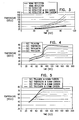
- Fig. 3 is a graph showing experimental results of five pieces of tissue that were heated in a control experiment, conducted in accordance with some applications of the present invention.
- the pieces of tissue were each mounted on a polystyrene board, using mounting pins, at a distance of 55 mm from an RF generator.
- the RF generator irradiated each piece of tissue for several time intervals: 30 sec, 50 sec, 80 sec, and 100 sec.
- the temperature of each of the pieces of tissue was measured immediately after the tissue was irradiated, using a k-type thermocouple.
- the maximum temperature in the tissue following the irradiation of the tissue is shown in Table 4, and is plotted on the graph of Fig. 3 .
- the ambient temperature was 24.2 C - 25 C.
- the irradiation of the pieces was done in accordance with the following protocol:
- Fig. 4 is a graph showing experimental results of four pieces of tissue that were injected with phase-change materials and were heated, in accordance with some applications of the present invention.
- the pieces of tissue were each mounted on a polystyrene board, using mounting pins, at a distance of 55 mm from an RF generator.
- a 40 mm reflector was mounted on the RF generator and the generator irradiated each piece of tissue for several time intervals: 30 sec, 50, sec, 80 sec, 100 sec, and 180 sec.
- the maximum temperature of the tissue following the irradiation of the tissue was measured using a k-type thermocouple, and the results shown in Table 5, and are plotted on the graph of Fig. 4 .
- the ambient temperature was 24.2 C - 25 C.
- the irradiation of the pieces was done in accordance with the following protocol:
- phase-change materials Use of phase-change materials is seen in Fig. 4 to produce prolonged periods of stable maximum tissue temperature during continued application of energy.
- FIG. 5 is a graph showing experimental results of four pieces of tissue that were injected with phase-change materials and into which carbon cylinders were inserted, in accordance with some applications of the present invention.
- Four pieces of tissue each weighing 13 grams, were cut from either turkey liver, chicken chest, or calf liver.
- Carbon cylinders, each cylinder having a diameter of 0.9 mm and a length of 20 mm to 40 mm were inserted into each of the pieces of tissue at intervals of 10 mm.
- the pieces of tissue were each mounted on a polystyrene board, using mounting pins, at a distance of 55 mm from an RF generator.
- a 40 mm reflector was mounted on the RF generator.
- Each of the pieces of tissue was heated for several time intervals.
- the maximum temperature measured within each of the pieces of tissue following each of these time intervals was measured using a k-type thermocouple, and is shown in Table 6, and plotted on the graph of Fig. 5 .
- the ambient temperature was 24.2 C - 25 C.
- the irradiation of the pieces was done in accordance with the following protocol:
- the piece injected with the trilaurin-based mixture reached its phase-change temperature quickly, and maintained this temperature throughout the experiment.
- a phase-change material is inserted into a subject's tissue to facilitate the heating of the tissue to a given temperature and to inhibit the tissue from being heated above the given temperature.
- an energy absorbing element 36 is inserted into a subject's tissue to facilitate the heating of the tissue, for example, by drawing energy from a heating device to the tissue, as described hereinabove.
- energy absorbers that are biocompatible and that do not show artifacts in during imaging (e.g., X ray or MRI imaging) of the tissue, such as carbon or graphite cylinders, are inserted into the tissue.
- carbon cylinders each of the cylinders having a diameter that is at least 0.9 mm, are inserted into the tissue.
- an implantable, biocompatible metal such as nitinol, stainless steel, cobalt and/or chromium, is used as an energy absorbing element.
- phase-change molecules that are coupled to molecules (such as glucose molecules), which, in turn, are coupled to cancer cells.
- molecules such as glucose molecules
- the temperature of the region in which the phase-change molecules are disposed rises, but does not rise above the phase-change temperature of the phase-change molecules. This is because, at the phase-change temperature, the heat that is transmitted toward the region is absorbed by the phase-change molecules as latent heat. The heating of the phase-change molecules typically heats the cancer cells, thereby killing the cancer cells.
- FIG. 6 is a schematic illustration of an implantable element 60, not part of the invention, implanted within a portion of a subject's body, for example, a blood vessel 70 of the subject.
- the element includes a shape-memory material having a transformation temperature.
- the implantable element performs a first therapeutic function with respect to the blood vessel when the shape-memory material is in a first shape.
- An energy applicator 72 changes the shape-memory material from the first shape to a second shape, by raising a temperature of the shape-memory material to the transformation temperature.
- the second shape is maintained even after energy applicator 72 no longer applies energy to implantable element 60, and the temperature of implantable element 70 returns to body temperature.
- the implantable element performs a second therapeutic function with respect to the portion, the second therapeutic function being qualitatively different from the first therapeutic function.
- energy applicator 72 is an energy applicator as is known in the art, for example, an RF generator, an ultrasound transducer, and/or a magnetic field generator.
- element 60 contains a shape-memory material as is known in the art, for example, nitinol, copper-zinc-aluminum-nickel, and/or copper-aluminum-nickel.
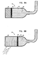
- Implantable element 60 is a stent (as shown), which, in a first configuration thereof, supports a narrowed blood vessel 70, in order to open, and/or widen the blood vessel, as shown in Fig. 7A .
- Implantable element 60 is typically maintained in its first configuration for a prolonged period (e.g., weeks or months, or a different period of time), until a desired effect of the stent has been attained.
- energy applicator 72 raises the temperature of the stent to the transformation temperature of the shape change material of the stent, and the shape of the stent changes to the shape of a venturi tube, as shown in Fig. 7B , i.e., a central portion of the stent narrows.
- the stent when the stent is in the second configuration, it causes a controlled narrowing of blood vessel 70, region 73 of the blood vessel wall collapsing to the outer wall of the stent. As a result of the narrowing of the blood vessel, blood flow (indicated by arrow 78) upstream of region 73 is impeded. In response to sensing impeded blood flow, the body generates a new blood vessel 80 (not to scale), which circumvents the constriction of region 73. When the new blood vessel has generated, the blood flows through the new blood vessel, in the direction of arrow 82.
- This general physiological response of the body to an implanted venturi stent is described in PCT Publication WO 03/028522 to Ben Muvhar .
- a stent contains a shape-memory material is implanted in an artery of a subject's brain, for example, a cerebral artery of the subject.
- the stent supports the artery in order to open, and/or widen the artery.
- the temperature of the stent is raised to the transformation temperature of the shape-memory material of the stent, causing the stent to expand.
- the expanded stent is used to facilitate drug delivery across the subject's blood brain barrier, by increasing the intercellular gaps of the blood brain barrier.
- a stent contains a shape-memory material is implanted in a subject's esophagus, in a vicinity of an esophageal tumor.
- the stent supports the esophagus in order to open the esophagus in the vicinity of the tumor.
- the stent is configured to have a degree of flexibility that is sufficient to facilitate peristalsis through the esophagus, while the stent is disposed in the esophagus in the first configuration thereof.
- the temperature of the stent is raised to the transformation temperature of the shape-memory material of the stent, causing the stent to expand.
- the stent is expanded by a healthcare professional, in response to the tumor growing to a size such that it interferes with the ingestion of food by the subject.
- the expanded stent pushes back the tumor, thereby widening the esophagus.
- An arrangement not part of the invention includes a shape-memory material that is implanted in a subject's bone, the bone requiring elongation, for example, subsequent to surgery on the bone.
- the shape-memory material is surgically coupled to the bone. Subsequently (for example, a day, a week or a month after the implantation), the temperature of the shape-memory material is raised, causing the shape-memory material to expand, and, consequently, causing the bone to lengthen.
- the shape-memory material is further expanded by repeatedly heating the shape-memory material (for example, once every day, every week or every month, or as required), during the period of the bone elongation.
- FIGs. 8A-B are schematic illustrations of a portion 90 of a drug pump, not according to the present invention.
- Portion 90 includes a drug chamber 92, a shape-memory material 94, and a separator 96 (e.g., a piston that separates the shape-memory material and the drug chamber).
- a separator 96 e.g., a piston that separates the shape-memory material and the drug chamber.
- the shape-memory material is heated to its transformation temperature, for a given time period.
- the shape-memory material Upon heating the shape-memory material to the transformation temperature (e.g., a temperature of 40-60 C), the shape-memory material expands, as it undergoes a shape change, and releases the given quantity of the drug by advancing separator 96 through a given distance, as shown in Fig. 8B .
- the transformation temperature e.g., a temperature of 40-60 C
- the heating of the shape-memory material is terminated before the shape-memory material has fully undergone its shape-change.
- the shape-memory material is again heated to its transformation temperature, thereby causing the shape-memory material to further expand, as it continues to undergo the shape change, thus releasing more of the drug.
- shape-memory material 94 is a shape-memory material that is known in the art, for example, nitinol, copper-zinc-aluminum-nickel, and/or copper-aluminum-nickel.
- shape-memory material expands by 5 percent to 25 percent, e.g. 8 percent to 12 percent, in each interaction in which the shape-memory material is heated.
- portion 90 comprises a portion of an implantable drug pump, the drug pump being as known in the art.
- portion 90 is used to administer insulin to a diabetic subject.
- the portion is used to administer a chemotherapy agent to a subject suffering from cancer.
Claims (12)
- Dispositif permettant de tuer des cellules cancéreuses chez un sujet, le sujet ayant des cellules cancéreuses et des cellules saines et le dispositif comprenant :une pluralité de premières molécules (40) configurées pour être couplées dans une plus grande mesure aux cellules cancéreuses qu'aux cellules saines en réponse à une administration au sujet ;une pluralité d'agglomérats (42) de secondes molécules, chacun des agglomérats étant couplé à l'une respective des premières molécules ; etune unité de transmission d'énergie (50) configurée pour tuer des cellules cancéreuses couplées aux premières molécules en chauffant les cellules cancéreuses par transmission vers les agglomérats d'une énergie qui produit un chauffage sélectif des agglomérats,les secondes molécules étant des molécules à changement de phase, l'unité de transmission d'énergie (50) étant configurée pour chauffer les agglomérats (42) à une température de fusion des molécules à changement de phase et les molécules à changement de phase étant configurées pour absorber la chaleur de fusion latente en réponse au chauffage des agglomérats,caractérisé en ce que l'unité de transmission d'énergie (50) est configurée pour transmettre l'énergie à une fréquence de résonance des molécules à changement de phase.
- Dispositif selon la revendication 1, dans lequel l'unité de transmission d'énergie (50) est configurée pour rompre les membranes des cellules cancéreuses par chauffage des cellules cancéreuses.
- Dispositif selon la revendication 1, dans lequel les molécules à changement de phase comprennent des molécules de paraffine.
- Dispositif selon la revendication 1, dans lequel les molécules à changement de phase comprennent des molécules à changement de phase organiques.
- Dispositif selon la revendication 1, dans lequel l'unité de transmission d'énergie (50) est configurée pour chauffer les agglomérats (42) de manière à ce que moins de la totalité des molécules à changement de phase de chaque agglomérat subisse le changement de phase sélectionné en réponse au chauffage des agglomérats.
- Dispositif selon la revendication 1, dans lequel les premières molécules (40) comprennent des molécules de glucose.
- Dispositif selon la revendication 1, dans lequel la température de changement de phase des agglomérats (42) de molécules à changement de phase est entre 60 et 80 °C.
- Dispositif selon la revendication 1, dans lequel la température de changement de phase des agglomérats (42) de molécules à changement de phase est entre 45 et 60 °C.
- Dispositif selon l'une quelconque des revendications 1-8, dans lequel l'unité de transmission d'énergie (50) est configurée pour chauffer les agglomérats de manière à ce que la température des agglomérats ne dépasse pas la température de changement de phase des molécules à changement de phase en réponse au chauffage des agglomérats.
- Dispositif selon la revendication 9, dans lequel l'unité de transmission d'énergie (50) est configurée pour interrompre la transmission d'énergie en réponse à une indication de la température des agglomérats.
- Dispositif selon la revendication 10, dans lequel l'unité de transmission d'énergie (50) est configurée pour détecter une température des agglomérats (42) et pour interrompre la transmission d'énergie en réponse à la température détectée.
- Dispositif selon la revendication 10, dans lequel l'unité de transmission d'énergie (50) est configurée pour interrompre la transmission d'énergie en réponse à une durée de transmission d'énergie.
Priority Applications (1)
| Application Number | Priority Date | Filing Date | Title |
|---|---|---|---|
| EP14192528.9A EP2868299B1 (fr) | 2009-08-24 | 2010-08-22 | Matériaux de changement de phase et de changement de forme |
Applications Claiming Priority (4)
| Application Number | Priority Date | Filing Date | Title |
|---|---|---|---|
| US27508909P | 2009-08-24 | 2009-08-24 | |
| US27506809P | 2009-08-24 | 2009-08-24 | |
| US27507109P | 2009-08-24 | 2009-08-24 | |
| PCT/IL2010/000683 WO2011024159A2 (fr) | 2009-08-24 | 2010-08-22 | Matériaux à changement de phase et à changement de forme |
Related Child Applications (1)
| Application Number | Title | Priority Date | Filing Date |
|---|---|---|---|
| EP14192528.9A Division EP2868299B1 (fr) | 2009-08-24 | 2010-08-22 | Matériaux de changement de phase et de changement de forme |
Publications (3)
| Publication Number | Publication Date |
|---|---|
| EP2470131A2 EP2470131A2 (fr) | 2012-07-04 |
| EP2470131A4 EP2470131A4 (fr) | 2013-04-17 |
| EP2470131B1 true EP2470131B1 (fr) | 2014-11-12 |
Family
ID=43628494
Family Applications (2)
| Application Number | Title | Priority Date | Filing Date |
|---|---|---|---|
| EP10811360.6A Active EP2470131B1 (fr) | 2009-08-24 | 2010-08-22 | Matériaux à changement de phase |
| EP14192528.9A Active EP2868299B1 (fr) | 2009-08-24 | 2010-08-22 | Matériaux de changement de phase et de changement de forme |
Family Applications After (1)
| Application Number | Title | Priority Date | Filing Date |
|---|---|---|---|
| EP14192528.9A Active EP2868299B1 (fr) | 2009-08-24 | 2010-08-22 | Matériaux de changement de phase et de changement de forme |
Country Status (5)
| Country | Link |
|---|---|
| US (3) | US9572695B2 (fr) |
| EP (2) | EP2470131B1 (fr) |
| JP (3) | JP5706420B2 (fr) |
| IL (2) | IL244478B (fr) |
| WO (1) | WO2011024159A2 (fr) |
Cited By (1)
| Publication number | Priority date | Publication date | Assignee | Title |
|---|---|---|---|---|
| CN107206082A (zh) * | 2014-11-25 | 2017-09-26 | 纽菲斯有限公司 | 相变纳米粒子 |
Families Citing this family (11)
| Publication number | Priority date | Publication date | Assignee | Title |
|---|---|---|---|---|
| EP2470131B1 (fr) | 2009-08-24 | 2014-11-12 | New Phase Ltd | Matériaux à changement de phase |
| US9370398B2 (en) | 2012-08-07 | 2016-06-21 | Covidien Lp | Microwave ablation catheter and method of utilizing the same |
| US9770593B2 (en) | 2012-11-05 | 2017-09-26 | Pythagoras Medical Ltd. | Patient selection using a transluminally-applied electric current |
| CN107334525B (zh) | 2012-11-05 | 2019-10-08 | 毕达哥拉斯医疗有限公司 | 受控组织消融 |
| EP3744391B1 (fr) | 2013-04-30 | 2023-03-01 | Alcon Inc. | Systèmes de traitement de maladies oculaires |
| US9763827B2 (en) | 2013-04-30 | 2017-09-19 | Tear Film Innovations, Inc. | Systems and methods for the treatment of eye conditions |
| EP3139853B1 (fr) | 2014-05-07 | 2018-12-19 | Pythagoras Medical Ltd. | Dispositif d'ablation de tissu commandées |
| US10383685B2 (en) | 2015-05-07 | 2019-08-20 | Pythagoras Medical Ltd. | Techniques for use with nerve tissue |
| US11678932B2 (en) | 2016-05-18 | 2023-06-20 | Symap Medical (Suzhou) Limited | Electrode catheter with incremental advancement |
| US10974063B2 (en) | 2016-06-30 | 2021-04-13 | Alcon Inc. | Light therapy for eyelash growth |
| CA3054033A1 (fr) | 2017-02-22 | 2018-08-30 | Raphael Hof | Nanoparticule a changement de phase |
Citations (1)
| Publication number | Priority date | Publication date | Assignee | Title |
|---|---|---|---|---|
| US20060142749A1 (en) * | 2001-07-25 | 2006-06-29 | Robert Ivkov | Magnetic nanoscale particle compositions, and therapeutic methods related thereto |
Family Cites Families (96)
| Publication number | Priority date | Publication date | Assignee | Title |
|---|---|---|---|---|
| US4106488A (en) * | 1974-08-20 | 1978-08-15 | Robert Thomas Gordon | Cancer treatment method |
| US4096616A (en) | 1976-10-28 | 1978-06-27 | General Electric Company | Method of manufacturing a concentric tube heat exchanger |
| US4204573A (en) | 1977-05-09 | 1980-05-27 | Pvi Industries, Inc. | Heat exchanger with concentric flow tubes |
| US4392040A (en) * | 1981-01-09 | 1983-07-05 | Rand Robert W | Induction heating apparatus for use in causing necrosis of neoplasm |
| US4569836A (en) * | 1981-08-27 | 1986-02-11 | Gordon Robert T | Cancer treatment by intracellular hyperthermia |
| US4440217A (en) | 1982-06-10 | 1984-04-03 | Stieler Scott M | Counterflow heat exchanger |
| US4747826A (en) | 1983-06-08 | 1988-05-31 | University Of Pittsburgh | Rapid venous infusion system |
| US4678460A (en) | 1985-02-11 | 1987-07-07 | Rosner Mark S | Portable rapid massive parenteral fluid warming and infusion apparatus |
| US4983159A (en) * | 1985-03-25 | 1991-01-08 | Rand Robert W | Inductive heating process for use in causing necrosis of neoplasms at selective frequencies |
| US5003991A (en) | 1987-03-31 | 1991-04-02 | Olympus Optical Co., Ltd. | Hyperthermia apparatus |
| US5153827A (en) | 1989-01-30 | 1992-10-06 | Omni-Flow, Inc. | An infusion management and pumping system having an alarm handling system |
| JPH03178668A (ja) | 1989-12-06 | 1991-08-02 | Senko Ika Kogyo Kk | 熱交換器 |
| EP0543498B1 (fr) | 1991-11-20 | 1998-04-08 | Kabushiki Kaisha Riken | Poudre injectable pour la thérapie du cancer |
| US5217363A (en) | 1992-06-03 | 1993-06-08 | Gaz Metropolitan & Co., Ltd. And Partnership | Air-cooled oxygen gas burner assembly |
| US5318557A (en) | 1992-07-13 | 1994-06-07 | Elan Medical Technologies Limited | Medication administering device |
| US5964744A (en) | 1993-01-04 | 1999-10-12 | Menlo Care, Inc. | Polymeric medical device systems having shape memory |
| US5716410A (en) | 1993-04-30 | 1998-02-10 | Scimed Life Systems, Inc. | Temporary stent and method of use |
| US5385540A (en) | 1993-05-26 | 1995-01-31 | Quest Medical, Inc. | Cardioplegia delivery system |
| IL108832A (en) | 1994-03-03 | 1999-12-31 | Medinol Ltd | Urological stent and positioning device for it |
| US5545210A (en) | 1994-09-22 | 1996-08-13 | Advanced Coronary Technology, Inc. | Method of implanting a permanent shape memory alloy stent |
| US6059810A (en) | 1995-05-10 | 2000-05-09 | Scimed Life Systems, Inc. | Endovascular stent and method |
| US5658234A (en) | 1995-07-24 | 1997-08-19 | J. D. Technologies, Inc. | Method for treating tumors |
| CA2241844C (fr) | 1996-01-18 | 2001-08-14 | Henry W. Palermo | Ecarteur a mailles pour echangeur thermique |
| US5830179A (en) | 1996-04-09 | 1998-11-03 | Endocare, Inc. | Urological stent therapy system and method |
| US6072154A (en) | 1996-09-05 | 2000-06-06 | Medtronic, Inc. | Selectively activated shape memory device |
| US6007573A (en) * | 1996-09-18 | 1999-12-28 | Microtherapeutics, Inc. | Intracranial stent and method of use |
| US6451044B1 (en) | 1996-09-20 | 2002-09-17 | Board Of Regents, The University Of Texas System | Method and apparatus for heating inflammed tissue |
| US5984893A (en) | 1997-03-27 | 1999-11-16 | Ward; Roger T. | Blood infusion control system |
| US7041941B2 (en) | 1997-04-07 | 2006-05-09 | Patented Medical Solutions, Llc | Medical item thermal treatment systems and method of monitoring medical items for compliance with prescribed requirements |
| DE19745890C1 (de) * | 1997-10-17 | 1999-03-25 | Inst Physikalische Hochtech Ev | Marker für eine Darm-Diagnostik und Darm-Therapie |
| US6120534A (en) | 1997-10-29 | 2000-09-19 | Ruiz; Carlos E. | Endoluminal prosthesis having adjustable constriction |
| US6379378B1 (en) | 2000-03-03 | 2002-04-30 | Innercool Therapies, Inc. | Lumen design for catheter |
| US7235096B1 (en) | 1998-08-25 | 2007-06-26 | Tricardia, Llc | Implantable device for promoting repair of a body lumen |
| US6585692B1 (en) | 1999-02-19 | 2003-07-01 | Alsius Corporation | Method and system for patient temperature management and central venous access |
| DE19921088C2 (de) | 1999-04-30 | 2003-08-07 | Magforce Applic Gmbh | Stent zur Offenhaltung gangartiger Strukturen |
| JP2003509098A (ja) | 1999-09-17 | 2003-03-11 | エンドルミナル セラピューティクス, インコーポレイテッド | 医用移植片のセンシング、インタロゲーティング、記憶、遠隔機器を用いた通信、測定および応答 |
| US6554791B1 (en) | 1999-09-29 | 2003-04-29 | Smisson-Cartledge Biomedical, Llc | Rapid infusion system |
| IL153753A0 (en) | 2002-12-30 | 2003-07-06 | Neovasc Medical Ltd | Varying-diameter vascular implant and balloon |
| US6953476B1 (en) | 2000-03-27 | 2005-10-11 | Neovasc Medical Ltd. | Device and method for treating ischemic heart disease |
| US7120489B2 (en) | 2000-05-08 | 2006-10-10 | Brainsgate, Ltd. | Method and apparatus for stimulating the sphenopalatine ganglion to modify properties of the BBB and cerebral blood flow |
| WO2003105658A2 (fr) | 2002-06-14 | 2003-12-24 | Brainsgate Ltd. | Procedes et systemes de gestion de la maladie d'alzheimer |
| US7146209B2 (en) | 2000-05-08 | 2006-12-05 | Brainsgate, Ltd. | Stimulation for treating eye pathologies |
| US7640062B2 (en) | 2000-05-08 | 2009-12-29 | Brainsgate Ltd. | Methods and systems for management of alzheimer's disease |
| US7117033B2 (en) | 2000-05-08 | 2006-10-03 | Brainsgate, Ltd. | Stimulation for acute conditions |
| US6805711B2 (en) | 2000-06-02 | 2004-10-19 | 3F Therapeutics, Inc. | Expandable medical implant and percutaneous delivery |
| AU5699900A (en) | 2000-06-26 | 2002-01-08 | Leonidas Diamantopoulos | Method and apparatus for external non-invasive heating of metallic implants by use of alternating magnetic fields |
| US8372139B2 (en) | 2001-02-14 | 2013-02-12 | Advanced Bio Prosthetic Surfaces, Ltd. | In vivo sensor and method of making same |
| US6768921B2 (en) | 2000-12-28 | 2004-07-27 | Z-Tech (Canada) Inc. | Electrical impedance method and apparatus for detecting and diagnosing diseases |
| US6390185B1 (en) | 2001-03-06 | 2002-05-21 | Richard A. Proeschel | Annular flow concentric tube recuperator |
| DE10113659B4 (de) | 2001-03-21 | 2006-10-26 | Triton BioSystems Inc., Chelmsford | Metallischer medizinischer Stent |
| US6746439B2 (en) | 2001-04-19 | 2004-06-08 | Jay Alan Lenker | Method and apparatus for fluid administration with distributed heating |
| US7074175B2 (en) | 2001-07-25 | 2006-07-11 | Erik Schroeder Handy | Thermotherapy via targeted delivery of nanoscale magnetic particles |
| AU2002337598A1 (en) | 2001-10-04 | 2003-04-14 | Neovasc Medical Ltd. | Flow reducing implant |
| US7048756B2 (en) * | 2002-01-18 | 2006-05-23 | Apasara Medical Corporation | System, method and apparatus for evaluating tissue temperature |
| WO2003066132A1 (fr) | 2002-02-07 | 2003-08-14 | Medela Ag | Embout tire-lait |
| US8709488B2 (en) | 2002-02-14 | 2014-04-29 | Gholam A. Peyman | Method and composition for hyperthermally treating cells |
| US7684859B2 (en) | 2002-04-25 | 2010-03-23 | Brainsgate Ltd. | Stimulation of the OTIC ganglion for treating medical conditions |
| TWI313188B (en) | 2002-09-12 | 2009-08-11 | Shell Int Research | Catalytic conversion of an organic carbonate |
| US20040059385A1 (en) | 2002-09-25 | 2004-03-25 | Yu Tsung I. | Low frequency assistor for electric-stimulating breast acupuncture point portions of a human body |
| US7112273B2 (en) | 2002-09-27 | 2006-09-26 | Nxstage Medical, Inc. | Volumetric fluid balance control for extracorporeal blood treatment |
| US20040180086A1 (en) | 2002-10-11 | 2004-09-16 | Zebunnissa Ramtoola | Gastro-retentive levodopa delivery form |
| US7560160B2 (en) | 2002-11-25 | 2009-07-14 | Materials Modification, Inc. | Multifunctional particulate material, fluid, and composition |
| WO2004066903A2 (fr) | 2003-01-29 | 2004-08-12 | E-Pill Pharma Ltd. | Apport de medicament actif dans le tube digestif |
| AU2003904086A0 (en) * | 2003-08-04 | 2003-08-21 | Cochlear Limited | Implant battery short circuit protection |
| US20050074506A1 (en) | 2003-10-02 | 2005-04-07 | Brainsgate Ltd. | Targeted release of nitric oxide in the CNS circulation for modulating the BBB and treating disorders |
| US7270910B2 (en) * | 2003-10-03 | 2007-09-18 | Black & Decker Inc. | Thermal management systems for battery packs |
| US20050090732A1 (en) * | 2003-10-28 | 2005-04-28 | Triton Biosystems, Inc. | Therapy via targeted delivery of nanoscale particles |
| US9040090B2 (en) | 2003-12-19 | 2015-05-26 | The University Of North Carolina At Chapel Hill | Isolated and fixed micro and nano structures and methods thereof |
| US8055347B2 (en) | 2005-08-19 | 2011-11-08 | Brainsgate Ltd. | Stimulation for treating brain events and other conditions |
| US8010189B2 (en) | 2004-02-20 | 2011-08-30 | Brainsgate Ltd. | SPG stimulation for treating complications of subarachnoid hemorrhage |
| US7510555B2 (en) * | 2004-05-07 | 2009-03-31 | Therm Med, Llc | Enhanced systems and methods for RF-induced hyperthermia |
| US20050251234A1 (en) | 2004-05-07 | 2005-11-10 | John Kanzius | Systems and methods for RF-induced hyperthermia using biological cells and nanoparticles as RF enhancer carriers |
| US20050283327A1 (en) | 2004-06-21 | 2005-12-22 | Bowman Catherine M | Breast feeding monitoring device and method |
| US7377941B2 (en) | 2004-06-29 | 2008-05-27 | Micardia Corporation | Adjustable cardiac valve implant with selective dimensional adjustment |
| US20060083694A1 (en) | 2004-08-07 | 2006-04-20 | Cabot Corporation | Multi-component particles comprising inorganic nanoparticles distributed in an organic matrix and processes for making and using same |
| CA2581272A1 (fr) | 2004-09-22 | 2006-05-18 | Lee R. Guterman | Systeme de traitement d'anevrisme cranien |
| EP1819399A1 (fr) * | 2004-12-09 | 2007-08-22 | Palomar Medical Technologies, Inc. | Appareil buccal avec mecanisme de transfert de chaleur |
| US20060276882A1 (en) | 2005-04-11 | 2006-12-07 | Cook Incorporated | Medical device including remodelable material attached to frame |
| US7357815B2 (en) | 2005-04-21 | 2008-04-15 | Micardia Corporation | Dynamically adjustable implants and methods for reshaping tissue |
| CN100336598C (zh) | 2005-06-13 | 2007-09-12 | 天津大学 | 自换热型催化剂评价反应器 |
| TWI314465B (en) | 2005-12-30 | 2009-09-11 | Ind Tech Res Inst | Thermosensitive nanostructure for hyperthermia treatment |
| GB0605672D0 (en) | 2006-03-22 | 2006-05-03 | Univ Keele | Indirect heating |
| US7919184B2 (en) | 2006-08-21 | 2011-04-05 | Mohapatra Satish C | Hybrid nanoparticles |
| US8518870B2 (en) | 2007-02-19 | 2013-08-27 | The Board Of Regents Of The University Of Oklahoma | Compositions and methods for cancer treatment using targeted carbon nanotubes |
| WO2008148014A2 (fr) | 2007-05-23 | 2008-12-04 | C.R. Bard, Inc. | Endoprothèse comportant un revêtement polymère |
| ES2913223T3 (es) | 2007-07-18 | 2022-06-01 | Silk Road Medical Inc | Sistemas para establecer flujo sanguíneo arterial carotídeo retrógrado |
| ES2320837B1 (es) | 2007-07-26 | 2010-03-04 | Consejo Superior De Investigaciones Cientificas | Dispositivo de hipertermia y su utilizacion con nanoparticulas. |
| US20090082832A1 (en) | 2007-09-25 | 2009-03-26 | Boston Scientific Neuromodulation Corporation | Thermal Management of Implantable Medical Devices |
| US20130078288A1 (en) | 2007-11-21 | 2013-03-28 | Chun Ho Yu | Method of Treating Cancer |
| US8326426B2 (en) * | 2009-04-03 | 2012-12-04 | Enteromedics, Inc. | Implantable device with heat storage |
| EP2470131B1 (fr) | 2009-08-24 | 2014-11-12 | New Phase Ltd | Matériaux à changement de phase |
| US20110195526A1 (en) | 2010-02-11 | 2011-08-11 | University Of Central Florida Research Foundation | Thermo-probes, methods of making thermo-probes, and methods of detection using thermo-probes |
| CN101836915B (zh) | 2010-03-12 | 2012-07-04 | 重庆大学 | 热物理治疗中对正常组织进行热防护的磁性相变微胶囊 |
| US8197471B1 (en) | 2011-02-14 | 2012-06-12 | Samuel Harry Tersigni | Core-excited nanoparticles and methods of their use in the diagnosis and treatment of disease |
| WO2014055539A1 (fr) | 2012-10-01 | 2014-04-10 | University Of Washington Through Its Center For Commercialization | Émulsions de nanoparticules |
| CN107206082B (zh) | 2014-11-25 | 2022-01-11 | 纽菲斯有限公司 | 相变纳米粒子 |
-
2010
- 2010-08-22 EP EP10811360.6A patent/EP2470131B1/fr active Active
- 2010-08-22 EP EP14192528.9A patent/EP2868299B1/fr active Active
- 2010-08-22 JP JP2012526180A patent/JP5706420B2/ja active Active
- 2010-08-22 WO PCT/IL2010/000683 patent/WO2011024159A2/fr active Application Filing
- 2010-08-22 US US13/392,037 patent/US9572695B2/en active Active
-
2014
- 2014-12-22 US US14/579,340 patent/US10492935B2/en active Active
-
2015
- 2015-02-26 JP JP2015037378A patent/JP5951059B2/ja active Active
-
2016
- 2016-03-08 IL IL244478A patent/IL244478B/en active IP Right Grant
- 2016-06-06 JP JP2016112337A patent/JP6291522B2/ja active Active
-
2018
- 2018-02-12 IL IL257476A patent/IL257476B/en active IP Right Grant
-
2019
- 2019-11-22 US US16/691,960 patent/US20200093621A1/en not_active Abandoned
Patent Citations (1)
| Publication number | Priority date | Publication date | Assignee | Title |
|---|---|---|---|---|
| US20060142749A1 (en) * | 2001-07-25 | 2006-06-29 | Robert Ivkov | Magnetic nanoscale particle compositions, and therapeutic methods related thereto |
Cited By (2)
| Publication number | Priority date | Publication date | Assignee | Title |
|---|---|---|---|---|
| CN107206082A (zh) * | 2014-11-25 | 2017-09-26 | 纽菲斯有限公司 | 相变纳米粒子 |
| CN107206082B (zh) * | 2014-11-25 | 2022-01-11 | 纽菲斯有限公司 | 相变纳米粒子 |
Also Published As
| Publication number | Publication date |
|---|---|
| JP6291522B2 (ja) | 2018-03-14 |
| IL244478B (en) | 2018-03-29 |
| US20200093621A1 (en) | 2020-03-26 |
| US10492935B2 (en) | 2019-12-03 |
| WO2011024159A2 (fr) | 2011-03-03 |
| WO2011024159A3 (fr) | 2011-04-21 |
| JP2015142741A (ja) | 2015-08-06 |
| EP2868299A2 (fr) | 2015-05-06 |
| EP2470131A4 (fr) | 2013-04-17 |
| US9572695B2 (en) | 2017-02-21 |
| IL257476A (en) | 2018-04-30 |
| JP2016195769A (ja) | 2016-11-24 |
| JP2013502294A (ja) | 2013-01-24 |
| EP2868299A3 (fr) | 2015-08-12 |
| IL257476B (en) | 2020-07-30 |
| JP5706420B2 (ja) | 2015-04-22 |
| US20150112423A1 (en) | 2015-04-23 |
| JP5951059B2 (ja) | 2016-07-13 |
| IL244478A0 (en) | 2016-04-21 |
| US20120221081A1 (en) | 2012-08-30 |
| EP2470131A2 (fr) | 2012-07-04 |
| EP2868299B1 (fr) | 2022-08-10 |
Similar Documents
| Publication | Publication Date | Title |
|---|---|---|
| US20200093621A1 (en) | Phase-change and shape-change materials | |
| EP3454737B1 (fr) | Implant de lit tumoral pour traitement multimodalité d'un tissu à risque entourant une cavité de résection | |
| Jang et al. | Current and future clinical applications of high-intensity focused ultrasound (HIFU) for pancreatic cancer | |
| CA2562699C (fr) | Systemes et procede servant a ameliorer l'ablation d'un tissu guidee par l'image | |
| CN104906698B (zh) | 神经的能量调节 | |
| Wong et al. | Ultrasound ablation enhances drug accumulation and survival in mammary carcinoma models | |
| Couture et al. | In vivo targeted delivery of large payloads with an ultrasound clinical scanner | |
| US20190076212A1 (en) | Transformative shape-memory polymer tissue cavity marker devices, systems and deployment methods | |
| Hwang et al. | Current status of clinical high-intensity focused ultrasound | |
| WO2006078770A2 (fr) | Creation d'espace provisoire entre les tissus corporels | |
| Jia et al. | The effects of artery occlusion on temperature homogeneity during hyperthermia in rabbit kidneys in vivo | |
| Wu | High intensity focused ultrasound (HIFU) ablation | |
| Vernon | Hyperthermia in cancer growth regulation | |
| WO2024076245A1 (fr) | Ablation par ultrasons améliorée par des bulles formées à partir d'une composition en grappe administrée à un patient | |
| Wootton et al. | Endocavitary Ultrasound Applicator for Hyperthermia Treatment of Cervical Cancer | |
| US20050118135A1 (en) | System and methods for inducing ischemia in cells | |
| Nakamura et al. | Poster Session “New Tochnology3” Joint Session with KAOC Annual Conference | |
| Gündüz | Magnetic Resonance Guided Focused Ultrasound Surgery (MRgFUS) | |
| Rathore et al. | Exploratory study on laser induced hyperthermia effected by local delivery of gold nanoshells in laboratory and animal tissue phantoms | |
| Chato et al. | Heat transfer in bioengineering and medicine | |
| Class et al. | Patent application title: IMAGEABLE ACTIVATABLE AGENT FOR RADIATION THERAPY AND METHOD AND SYSTEM FOR RADIATION THERAPY Inventors: David A. Jaffray (Etobicoke, CA) David A. Jaffray (Etobicoke, CA) Christine Allen (Toronto, CA) Devika Chithrani (Scarborough, CA) Jinzi Zheng (North York, CA) Justin Grant (Toronto, CA) Assignees: UNIVERSITY HEALTH NETWORK | |
| Trybus et al. | High intensity focused ultrasound therapy under magnetic resonance control |
Legal Events
| Date | Code | Title | Description |
|---|---|---|---|
| PUAI | Public reference made under article 153(3) epc to a published international application that has entered the european phase |
Free format text: ORIGINAL CODE: 0009012 |
|
| 17P | Request for examination filed |
Effective date: 20120322 |
|
| AK | Designated contracting states |
Kind code of ref document: A2 Designated state(s): AL AT BE BG CH CY CZ DE DK EE ES FI FR GB GR HR HU IE IS IT LI LT LU LV MC MK MT NL NO PL PT RO SE SI SK SM TR |
|
| DAX | Request for extension of the european patent (deleted) | ||
| A4 | Supplementary search report drawn up and despatched |
Effective date: 20130320 |
|
| RIC1 | Information provided on ipc code assigned before grant |
Ipc: A61F 7/03 20060101ALI20130312BHEP Ipc: A61N 1/40 20060101ALI20130312BHEP Ipc: A61F 7/00 20060101AFI20130312BHEP Ipc: A61F 7/02 20060101ALI20130312BHEP |
|
| RIN1 | Information on inventor provided before grant (corrected) |
Inventor name: HOF, REFAEL Inventor name: PEREVALOV, VALERY |
|
| RAP1 | Party data changed (applicant data changed or rights of an application transferred) |
Owner name: NEW PHASE LTD |
|
| GRAP | Despatch of communication of intention to grant a patent |
Free format text: ORIGINAL CODE: EPIDOSNIGR1 |
|
| INTG | Intention to grant announced |
Effective date: 20140613 |
|
| GRAS | Grant fee paid |
Free format text: ORIGINAL CODE: EPIDOSNIGR3 |
|
| GRAA | (expected) grant |
Free format text: ORIGINAL CODE: 0009210 |
|
| AK | Designated contracting states |
Kind code of ref document: B1 Designated state(s): AL AT BE BG CH CY CZ DE DK EE ES FI FR GB GR HR HU IE IS IT LI LT LU LV MC MK MT NL NO PL PT RO SE SI SK SM TR |
|
| REG | Reference to a national code |
Ref country code: GB Ref legal event code: FG4D |
|
| REG | Reference to a national code |
Ref country code: CH Ref legal event code: EP |
|
| REG | Reference to a national code |
Ref country code: AT Ref legal event code: REF Ref document number: 695287 Country of ref document: AT Kind code of ref document: T Effective date: 20141115 |
|
| REG | Reference to a national code |
Ref country code: IE Ref legal event code: FG4D |
|
| RAP2 | Party data changed (patent owner data changed or rights of a patent transferred) |
Owner name: NEW PHASE LTD |
|
| REG | Reference to a national code |
Ref country code: DE Ref legal event code: R096 Ref document number: 602010020252 Country of ref document: DE Effective date: 20141224 |
|
| REG | Reference to a national code |
Ref country code: SE Ref legal event code: TRGR |
|
| REG | Reference to a national code |
Ref country code: NL Ref legal event code: T3 |
|
| PG25 | Lapsed in a contracting state [announced via postgrant information from national office to epo] |
Ref country code: IS Free format text: LAPSE BECAUSE OF FAILURE TO SUBMIT A TRANSLATION OF THE DESCRIPTION OR TO PAY THE FEE WITHIN THE PRESCRIBED TIME-LIMIT Effective date: 20150312 Ref country code: ES Free format text: LAPSE BECAUSE OF FAILURE TO SUBMIT A TRANSLATION OF THE DESCRIPTION OR TO PAY THE FEE WITHIN THE PRESCRIBED TIME-LIMIT Effective date: 20141112 Ref country code: NO Free format text: LAPSE BECAUSE OF FAILURE TO SUBMIT A TRANSLATION OF THE DESCRIPTION OR TO PAY THE FEE WITHIN THE PRESCRIBED TIME-LIMIT Effective date: 20150212 Ref country code: PT Free format text: LAPSE BECAUSE OF FAILURE TO SUBMIT A TRANSLATION OF THE DESCRIPTION OR TO PAY THE FEE WITHIN THE PRESCRIBED TIME-LIMIT Effective date: 20150312 Ref country code: FI Free format text: LAPSE BECAUSE OF FAILURE TO SUBMIT A TRANSLATION OF THE DESCRIPTION OR TO PAY THE FEE WITHIN THE PRESCRIBED TIME-LIMIT Effective date: 20141112 Ref country code: LT Free format text: LAPSE BECAUSE OF FAILURE TO SUBMIT A TRANSLATION OF THE DESCRIPTION OR TO PAY THE FEE WITHIN THE PRESCRIBED TIME-LIMIT Effective date: 20141112 |
|
| PG25 | Lapsed in a contracting state [announced via postgrant information from national office to epo] |
Ref country code: CY Free format text: LAPSE BECAUSE OF FAILURE TO SUBMIT A TRANSLATION OF THE DESCRIPTION OR TO PAY THE FEE WITHIN THE PRESCRIBED TIME-LIMIT Effective date: 20141112 Ref country code: GR Free format text: LAPSE BECAUSE OF FAILURE TO SUBMIT A TRANSLATION OF THE DESCRIPTION OR TO PAY THE FEE WITHIN THE PRESCRIBED TIME-LIMIT Effective date: 20150213 Ref country code: LV Free format text: LAPSE BECAUSE OF FAILURE TO SUBMIT A TRANSLATION OF THE DESCRIPTION OR TO PAY THE FEE WITHIN THE PRESCRIBED TIME-LIMIT Effective date: 20141112 Ref country code: PL Free format text: LAPSE BECAUSE OF FAILURE TO SUBMIT A TRANSLATION OF THE DESCRIPTION OR TO PAY THE FEE WITHIN THE PRESCRIBED TIME-LIMIT Effective date: 20141112 Ref country code: HR Free format text: LAPSE BECAUSE OF FAILURE TO SUBMIT A TRANSLATION OF THE DESCRIPTION OR TO PAY THE FEE WITHIN THE PRESCRIBED TIME-LIMIT Effective date: 20141112 |
|
| PG25 | Lapsed in a contracting state [announced via postgrant information from national office to epo] |
Ref country code: CZ Free format text: LAPSE BECAUSE OF FAILURE TO SUBMIT A TRANSLATION OF THE DESCRIPTION OR TO PAY THE FEE WITHIN THE PRESCRIBED TIME-LIMIT Effective date: 20141112 Ref country code: DK Free format text: LAPSE BECAUSE OF FAILURE TO SUBMIT A TRANSLATION OF THE DESCRIPTION OR TO PAY THE FEE WITHIN THE PRESCRIBED TIME-LIMIT Effective date: 20141112 Ref country code: RO Free format text: LAPSE BECAUSE OF FAILURE TO SUBMIT A TRANSLATION OF THE DESCRIPTION OR TO PAY THE FEE WITHIN THE PRESCRIBED TIME-LIMIT Effective date: 20141112 Ref country code: SK Free format text: LAPSE BECAUSE OF FAILURE TO SUBMIT A TRANSLATION OF THE DESCRIPTION OR TO PAY THE FEE WITHIN THE PRESCRIBED TIME-LIMIT Effective date: 20141112 Ref country code: EE Free format text: LAPSE BECAUSE OF FAILURE TO SUBMIT A TRANSLATION OF THE DESCRIPTION OR TO PAY THE FEE WITHIN THE PRESCRIBED TIME-LIMIT Effective date: 20141112 |
|
| REG | Reference to a national code |
Ref country code: DE Ref legal event code: R097 Ref document number: 602010020252 Country of ref document: DE |
|
| PLBE | No opposition filed within time limit |
Free format text: ORIGINAL CODE: 0009261 |
|
| STAA | Information on the status of an ep patent application or granted ep patent |
Free format text: STATUS: NO OPPOSITION FILED WITHIN TIME LIMIT |
|
| 26N | No opposition filed |
Effective date: 20150813 |
|
| PG25 | Lapsed in a contracting state [announced via postgrant information from national office to epo] |
Ref country code: SI Free format text: LAPSE BECAUSE OF FAILURE TO SUBMIT A TRANSLATION OF THE DESCRIPTION OR TO PAY THE FEE WITHIN THE PRESCRIBED TIME-LIMIT Effective date: 20141112 |
|
| PG25 | Lapsed in a contracting state [announced via postgrant information from national office to epo] |
Ref country code: MC Free format text: LAPSE BECAUSE OF FAILURE TO SUBMIT A TRANSLATION OF THE DESCRIPTION OR TO PAY THE FEE WITHIN THE PRESCRIBED TIME-LIMIT Effective date: 20141112 |
|
| REG | Reference to a national code |
Ref country code: AT Ref legal event code: UEP Ref document number: 695287 Country of ref document: AT Kind code of ref document: T Effective date: 20141112 |
|
| REG | Reference to a national code |
Ref country code: FR Ref legal event code: PLFP Year of fee payment: 7 |
|
| PG25 | Lapsed in a contracting state [announced via postgrant information from national office to epo] |
Ref country code: MT Free format text: LAPSE BECAUSE OF FAILURE TO SUBMIT A TRANSLATION OF THE DESCRIPTION OR TO PAY THE FEE WITHIN THE PRESCRIBED TIME-LIMIT Effective date: 20141112 |
|
| PG25 | Lapsed in a contracting state [announced via postgrant information from national office to epo] |
Ref country code: HU Free format text: LAPSE BECAUSE OF FAILURE TO SUBMIT A TRANSLATION OF THE DESCRIPTION OR TO PAY THE FEE WITHIN THE PRESCRIBED TIME-LIMIT; INVALID AB INITIO Effective date: 20100822 Ref country code: BG Free format text: LAPSE BECAUSE OF FAILURE TO SUBMIT A TRANSLATION OF THE DESCRIPTION OR TO PAY THE FEE WITHIN THE PRESCRIBED TIME-LIMIT Effective date: 20141112 Ref country code: SM Free format text: LAPSE BECAUSE OF FAILURE TO SUBMIT A TRANSLATION OF THE DESCRIPTION OR TO PAY THE FEE WITHIN THE PRESCRIBED TIME-LIMIT Effective date: 20141112 |
|
| REG | Reference to a national code |
Ref country code: FR Ref legal event code: PLFP Year of fee payment: 8 |
|
| PG25 | Lapsed in a contracting state [announced via postgrant information from national office to epo] |
Ref country code: TR Free format text: LAPSE BECAUSE OF FAILURE TO SUBMIT A TRANSLATION OF THE DESCRIPTION OR TO PAY THE FEE WITHIN THE PRESCRIBED TIME-LIMIT Effective date: 20141112 |
|
| PG25 | Lapsed in a contracting state [announced via postgrant information from national office to epo] |
Ref country code: BE Free format text: LAPSE BECAUSE OF FAILURE TO SUBMIT A TRANSLATION OF THE DESCRIPTION OR TO PAY THE FEE WITHIN THE PRESCRIBED TIME-LIMIT Effective date: 20141112 |
|
| PG25 | Lapsed in a contracting state [announced via postgrant information from national office to epo] |
Ref country code: MK Free format text: LAPSE BECAUSE OF FAILURE TO SUBMIT A TRANSLATION OF THE DESCRIPTION OR TO PAY THE FEE WITHIN THE PRESCRIBED TIME-LIMIT Effective date: 20141112 |
|
| REG | Reference to a national code |
Ref country code: FR Ref legal event code: PLFP Year of fee payment: 9 |
|
| PG25 | Lapsed in a contracting state [announced via postgrant information from national office to epo] |
Ref country code: AL Free format text: LAPSE BECAUSE OF FAILURE TO SUBMIT A TRANSLATION OF THE DESCRIPTION OR TO PAY THE FEE WITHIN THE PRESCRIBED TIME-LIMIT Effective date: 20141112 |
|
| PGFP | Annual fee paid to national office [announced via postgrant information from national office to epo] |
Ref country code: NL Payment date: 20201112 Year of fee payment: 11 |
|
| PGFP | Annual fee paid to national office [announced via postgrant information from national office to epo] |
Ref country code: SE Payment date: 20201125 Year of fee payment: 11 Ref country code: AT Payment date: 20201119 Year of fee payment: 11 |
|
| PGFP | Annual fee paid to national office [announced via postgrant information from national office to epo] |
Ref country code: LU Payment date: 20210819 Year of fee payment: 12 |
|
| PGFP | Annual fee paid to national office [announced via postgrant information from national office to epo] |
Ref country code: IE Payment date: 20210819 Year of fee payment: 12 Ref country code: IT Payment date: 20210830 Year of fee payment: 12 |
|
| REG | Reference to a national code |
Ref country code: SE Ref legal event code: EUG |
|
| REG | Reference to a national code |
Ref country code: NL Ref legal event code: MM Effective date: 20210901 |
|
| REG | Reference to a national code |
Ref country code: AT Ref legal event code: MM01 Ref document number: 695287 Country of ref document: AT Kind code of ref document: T Effective date: 20210822 |
|
| PG25 | Lapsed in a contracting state [announced via postgrant information from national office to epo] |
Ref country code: AT Free format text: LAPSE BECAUSE OF NON-PAYMENT OF DUE FEES Effective date: 20210822 |
|
| PG25 | Lapsed in a contracting state [announced via postgrant information from national office to epo] |
Ref country code: SE Free format text: LAPSE BECAUSE OF NON-PAYMENT OF DUE FEES Effective date: 20210823 |
|
| PG25 | Lapsed in a contracting state [announced via postgrant information from national office to epo] |
Ref country code: NL Free format text: LAPSE BECAUSE OF NON-PAYMENT OF DUE FEES Effective date: 20210901 |
|
| PG25 | Lapsed in a contracting state [announced via postgrant information from national office to epo] |
Ref country code: LU Free format text: LAPSE BECAUSE OF NON-PAYMENT OF DUE FEES Effective date: 20220822 |
|
| P01 | Opt-out of the competence of the unified patent court (upc) registered |
Effective date: 20230512 |
|
| PG25 | Lapsed in a contracting state [announced via postgrant information from national office to epo] |
Ref country code: IT Free format text: LAPSE BECAUSE OF NON-PAYMENT OF DUE FEES Effective date: 20220822 Ref country code: IE Free format text: LAPSE BECAUSE OF NON-PAYMENT OF DUE FEES Effective date: 20220822 |
|
| PGFP | Annual fee paid to national office [announced via postgrant information from national office to epo] |
Ref country code: GB Payment date: 20230830 Year of fee payment: 14 Ref country code: CH Payment date: 20230906 Year of fee payment: 14 |
|
| PGFP | Annual fee paid to national office [announced via postgrant information from national office to epo] |
Ref country code: FR Payment date: 20230830 Year of fee payment: 14 Ref country code: DE Payment date: 20230830 Year of fee payment: 14 |