EP2469508A1 - Sound-absorbing body - Google Patents
Sound-absorbing body Download PDFInfo
- Publication number
- EP2469508A1 EP2469508A1 EP10809878A EP10809878A EP2469508A1 EP 2469508 A1 EP2469508 A1 EP 2469508A1 EP 10809878 A EP10809878 A EP 10809878A EP 10809878 A EP10809878 A EP 10809878A EP 2469508 A1 EP2469508 A1 EP 2469508A1
- Authority
- EP
- European Patent Office
- Prior art keywords
- sound
- absorbing body
- sound absorbing
- present
- absorbing
- Prior art date
- Legal status (The legal status is an assumption and is not a legal conclusion. Google has not performed a legal analysis and makes no representation as to the accuracy of the status listed.)
- Granted
Links
- 239000011148 porous material Substances 0.000 claims abstract description 52
- 239000010410 layer Substances 0.000 claims abstract description 35
- XLYOFNOQVPJJNP-UHFFFAOYSA-N water Substances O XLYOFNOQVPJJNP-UHFFFAOYSA-N 0.000 claims abstract description 19
- 239000012790 adhesive layer Substances 0.000 claims abstract description 11
- 238000000638 solvent extraction Methods 0.000 claims description 15
- 239000005871 repellent Substances 0.000 claims description 9
- 238000010521 absorption reaction Methods 0.000 description 26
- 229920005830 Polyurethane Foam Polymers 0.000 description 19
- 239000011496 polyurethane foam Substances 0.000 description 19
- 238000000034 method Methods 0.000 description 17
- 239000000463 material Substances 0.000 description 12
- 239000002390 adhesive tape Substances 0.000 description 10
- 239000012528 membrane Substances 0.000 description 6
- 230000000694 effects Effects 0.000 description 5
- 238000009434 installation Methods 0.000 description 5
- 238000005034 decoration Methods 0.000 description 4
- 239000000853 adhesive Substances 0.000 description 3
- 238000010586 diagram Methods 0.000 description 3
- 230000008569 process Effects 0.000 description 3
- 230000006835 compression Effects 0.000 description 2
- 238000007906 compression Methods 0.000 description 2
- 238000013461 design Methods 0.000 description 2
- 238000001035 drying Methods 0.000 description 2
- 239000004744 fabric Substances 0.000 description 2
- 238000005259 measurement Methods 0.000 description 2
- 239000004745 nonwoven fabric Substances 0.000 description 2
- 230000009467 reduction Effects 0.000 description 2
- JOYRKODLDBILNP-UHFFFAOYSA-N Ethyl urethane Chemical compound CCOC(N)=O JOYRKODLDBILNP-UHFFFAOYSA-N 0.000 description 1
- 230000003466 anti-cipated effect Effects 0.000 description 1
- 230000015572 biosynthetic process Effects 0.000 description 1
- 239000003795 chemical substances by application Substances 0.000 description 1
- 150000001875 compounds Chemical class 0.000 description 1
- 238000000748 compression moulding Methods 0.000 description 1
- 238000005516 engineering process Methods 0.000 description 1
- 230000001747 exhibiting effect Effects 0.000 description 1
- 239000005357 flat glass Substances 0.000 description 1
- 239000006260 foam Substances 0.000 description 1
- 238000002847 impedance measurement Methods 0.000 description 1
- 230000006872 improvement Effects 0.000 description 1
- 238000007373 indentation Methods 0.000 description 1
- 239000006193 liquid solution Substances 0.000 description 1
- 238000000691 measurement method Methods 0.000 description 1
- 238000012986 modification Methods 0.000 description 1
- 230000004048 modification Effects 0.000 description 1
- 238000012545 processing Methods 0.000 description 1
- 239000002356 single layer Substances 0.000 description 1
- 238000012546 transfer Methods 0.000 description 1
Images

Classifications
-
- G—PHYSICS
- G10—MUSICAL INSTRUMENTS; ACOUSTICS
- G10K—SOUND-PRODUCING DEVICES; METHODS OR DEVICES FOR PROTECTING AGAINST, OR FOR DAMPING, NOISE OR OTHER ACOUSTIC WAVES IN GENERAL; ACOUSTICS NOT OTHERWISE PROVIDED FOR
- G10K11/00—Methods or devices for transmitting, conducting or directing sound in general; Methods or devices for protecting against, or for damping, noise or other acoustic waves in general
- G10K11/16—Methods or devices for protecting against, or for damping, noise or other acoustic waves in general
-
- B—PERFORMING OPERATIONS; TRANSPORTING
- B60—VEHICLES IN GENERAL
- B60R—VEHICLES, VEHICLE FITTINGS, OR VEHICLE PARTS, NOT OTHERWISE PROVIDED FOR
- B60R13/00—Elements for body-finishing, identifying, or decorating; Arrangements or adaptations for advertising purposes
- B60R13/08—Insulating elements, e.g. for sound insulation
Definitions
- the present invention relates to a sound absorbing body wherein porous materials are layered.
- a sound absorbing method that uses the viscous resistance of air there is a method that uses a porous material, such as soft polyurethane foam, where sound is absorbed within the minute airspace through a portion of the vibrational energy being converted into thermal energy, when a sound wave enters into the porous material, due to the viscous resistance of the air, and due to friction with the surrounding.
- a porous material such as soft polyurethane foam
- the absorption is not necessarily uniform for sound waves across the audible frequency band, where the porous material is superior in terms of the sound absorption characteristics in the high-frequency range and vibrating the membrane or plate exhibits a peak in the sound absorption characteristics at the resonant frequency thereof.
- the sound absorption characteristics in the low-frequency band can be improved through a method of increasing the thickness, where effective sound absorption characteristics are present if the thickness is at least 1/4 the wavelength of the sound wave, but at a frequency of 100 Hz the thickness would be about 85 cm, and thus the locations wherein sound absorbing bodies with such thicknesses can be installed are inherently limited.
- the conventional sound absorbing body does not take into consideration acoustic reverberation in uses such as home audio and car audio, and usually sound absorption characteristics that are biased towards the high-frequency band or the low-frequency band, or towards a specific frequency, are seen.
- the respective sound absorbing bodies when used in combination, have been arrayed together for use, but in some cases there have been problems with variability in the acoustics depending on the listening point, and cases wherein installation has not been possible due to space problems.
- Patent Document 1 Japanese Unexamined Patent Application Publication 2007-34254
- the present invention is the result of focus on the conventional problem areas set forth above, and the object of the present invention is to provide a sound absorbing body that has sound absorbing characteristics that are desirable for the intended use, that is, in suppressing reverberation, within a room, of the sound waves outputted from a speaker or suppressing reverberation within a speaker enclosure, and in maintaining a high sound absorption rate in the mid-frequency band, with flat characteristics, and, in order to be used with ease in a typical home, has a simple structure, can be installed easily, and can be decorated.
- the sound absorbing body according to the present invention comprises a structured body of three or more layers comprising a plurality of porous materials having air pores within, wherein individual porous materials are bonded by an adhesive layer having a specific thickness, where one side of the structured body is provided on the sound source side, and the other side of the structured body has indentations and protrusions wherein the porous materials and air layers are disposed alternatingly, and is provided on a partitioning wall between the sound wave incident direction and the opposite side, to flatten the mid-frequency range sound absorption rates.
- the present invention given the configuration set forth above, is well-suited for use for home audio, car audio, and the like because of defect-free, essentially uniform sound-absorption effects in the mid-frequency range, which is the key portion in music, when compared to that which is conventional, given the distinctive features of this structure.
- a water-repellent treatment is performed on the porous materials, where water is shed through a water shedding path that is produced by the shape of the sound absorbing body in the present invention.
- the water-repellent treatment is performed so far as to reach into the interior of the porous materials, then there is no limitation on the location wherein it can be cut, given the water repulsion at any place within the sound absorbing body. Because of this, when used in car audio, or the like, it can be formed into a variety of shapes and sizes, depending on the model of car, and will be well-suited for use in cases wherein the sound absorbing body is installed within a door interior wherein rain and water may incur.
- the porous material is noncombustible, making it suitable for use in situations where non-combustibility is required as well.
- the porous material is a soft polyurethane foam for which the sound absorption rate has been increased through a hot compression treatment of Japanese Patent Application 2009-143759 , which is a previous application by the present inventor.
- the porous material uses a soft polyurethane foam wherein the hot compression treatment has been performed using a die wherein a decoration has been made to the surface of the die for performing the hot compression molding according to Japanese Patent Application 2009-143759 , which is a previous application by the present inventor, to apply decorations, to make it well-suited for use even when there are many opportunities to be seen directly, such as within a room.
- the porous material uses a soft polyurethane foam to which a flocking process has been performed, to make it well-suited for use even when there are many opportunities to be seen directly, such as within a room.
- the structural body is wrapped in a fabric, to make it well-suited for use even when there are many opportunities to be seen directly, such as within a room.
- the acoustic characteristics are improved and flattened through the sound absorbing body set forth in Claim 1 that is a structured body of three or more layers comprising a plurality of porous materials having air pores within, wherein individual porous materials are bonded by an adhesive layer having a specific thickness, where one side of the structured body is provided on the sound source side, and the other side of the structured body has a corrugated shape wherein the porous materials and air layers are disposed alternatingly.
- porous material on the partitioning wall side have a peak-and-valley shape makes it possible to control the sound absorption characteristics, without limiting the material, through adjusting the airspace/porous material ratio and the shape thereof.
- the structure is of porous material and the adhesive layer alone, installation is easy, and if a water-repellent porous material is used, the corrugated shape of the porous material layer on the partitioning wall side makes the sound absorbing body into a water-resistant sound absorbing body that also has a water-shedding function.
- FIG. 1 illustrates the structure of an example embodiment of a sound absorbing body according to the present invention.
- FIG. 1 is a schematic plan view diagram wherein an automobile door interior is viewed from above, and
- FIG. 2 is a schematic back view diagram of the product in the present invention.
- FIG. 1 - 1 and FIG. 1 - 3 are porous materials having pores in the interior thereof, where, in the present embodiment, each is made from a soft polyurethane foam 1 and 3.
- FIG. 1 - 2 is an adhesive layer for bonding these together, and, in the present embodiment, is a double-sided adhesive tape 2 that uses a non-woven fabric as the base material thereof.
- the porous material 1 shall be referred to as the first layer
- the adhesive layer 2 shall be referred to as the second layer
- the porous material 3 shall be referred to as the third layer.
- the space within the door is limited, where usually, when the window glass is down between the partitioning wall 6 and the partitioning wall 7, the spacing from the partitioning wall 6 is no more than 80 mm, and, in order to avoid interferences, the thickness of the sound absorbing body in the present embodiment is between 10 and 70 mm, and, preferably, between 30 and 60 mm.
- the sound absorbing body must be a water repelling-type water resistant sound absorbing body.
- a double-sided adhesive tape 2 is applied over the entirety of the back face of the soft polyurethane foam 1, and the soft polyurethane foams 3 are affixed side-to-side, without gaps, to the double-sided adhesive tape 2, with the bottom base 16-mm side being affixed, to produce a structured body according to the present invention with a length of 300 mm, a width of 300 mm, and a thickness of 40 mm.
- double-sided adhesive tapes 5 with widths of 10 mm are affixed to the 10 mm portions of the soft polyurethane foams 3 on the partitioning wall side of the sound absorbing body according to the present invention. This is in order to affix and install the sound absorbing body according to the present invention onto the partitioning wall 6, that is, onto the inside of the outer panel of the door.
- the product of the present invention was installed in the door of an actual automobile and sent once through an automatic car wash in a state wherein the window was closed, and the increases in mass of the sound absorbing bodies according to the present invention due to moisture incursion were compared for the water-resistant moisture absorbing body according to the present embodiment and a moisture absorbing body of the same shape to which the water-repellent treatment was not performed.
- the sound absorbing body according to the present embodiment can be considered to be exhibiting fully the effects of the water-repellent treatment, enabling use even as a sound absorbing body requiring water resistance, such as for car audio.
- the airspace in the third layer operates effectively as a water shedding path for the water that is repelled.
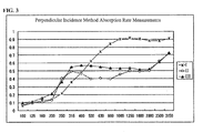
- the measurement data for the sound absorption rate using the perpendicular incidence method is shown next in FIG. 3 .
- I is for soft polyurethane foam alone
- III is for the sound absorbing body according to the present invention having a corrugated shape on the partitioning wall side
- II is for a sound absorbing body having the same layered structure as in the sound absorbing body of the present invention, but not having the corrugated shape on the partitioning wall side.
- the thickness for each of the sound absorbing bodies is 40 mm.
- the vertical axis of the graph shows the sound absorption rate, and the horizontal axis shows the frequency (Hz).
- the porous material that is a single material which has the sound absorbing property that rises on the right is caused to be essentially flat in the mid-frequency range through the use of the layered structure that is the same as in the sound absorbing body according to the present invention (II in the graph), and that the use of the shape of the sound absorbing body according to the present invention (III in the graph) further improves the flatness of the sound absorption rates in the mid-frequency range.
- the reason is thought to be that, with the first layer (the porous material 1), the second layer (the adhesive layer 2), and the third layer (the porous material 3), in the order in which the sound waves outputted from the speaker are incident in the sound absorbing body according to the present invention, first the sound in the mid-frequency through a high-frequency band is absorbed in the first layer, following which sound absorption through membrane vibration is performed on the mid-frequency through low-frequency band component that has passed through the first layer, using the attenuation within the membrane of the second layer, and, in the third layer, the alternating arrangement of the porous material and the air layers, which is the most critical point in the present invention, causes the physical strength of the third layer to be reduced so that, when the first layer and second layer, which are layered together, is treated as a compound monolithic membrane, this third layer fulfills the role of a spring that provides gentle support thereto, and, in addition, by the area with which is bonded to the partitioning wall being lines or being points, the sound absorbing body itself, in the
- the porous materials 1 and 3 used soft polyurethane foam, they may, of course, be other porous materials instead. Moreover, the porous materials 1 and 3 may either be made of identical materials or different materials. Moreover, preferably the porous material, with a thickness of 30 mm, has a value of at least 0.2 for the perpendicular incidence-method sound absorption rate NRC (noise reduction coefficient, a value wherein the calculated mean of sound absorption rates at the four frequencies of 250 Hz, 500 Hz, 1000 Hz, and 2000 Hz is rounded to 0 or 5 in the second digit after the decimal).
- NRC noise reduction coefficient
- a double-sided adhesive tape that used a non-woven fabric as the base material was used as the adhesive layer 2 in the present embodiment, instead a double-sided adhesive tape that uses a film as a base material, or a double-sided adhesive tape that has no base material, may be used instead.
- the three layers comprising the adhesive agent layer, the base material, and the adhesive agent layer may be considered to be a single layer.
- the structure may be one wherein there is only the adhesive agent for bonding the porous materials, preferably this adhesive layer has a breathability of no more than 50 cc/cm 2 /sec, where the breathability is measured based on JIS L-1096.
- the soft polyurethane foams 1 and 3 in the present embodiment use hot compression-molded soft polyurethane foams wherein the sound absorption rate has been improved, according to Japanese Patent Application 2009-143759 , which is a previous application by the present inventor.
- the soft polyurethane foam 1 in the present embodiment uses a hot compression-molded soft polyurethane foam, to which a decoration process has been performed, wherein the sound absorption rate has been improved, according to Japanese Patent Application 2009-143759 , which is a previous application by the present inventor.
- soft polyurethane foams 1 and 2 in the present embodiment preferably use soft polyurethane foams to which a flocking process has been performed.
- the soft polyurethane foams 1 and 3 in the present embodiment use a non-combustible porous material.
- the structured body in the present invention is wrapped in a fabric.
- the present invention is not limited to the form of embodiment set forth above, but rather the thicknesses and shapes of the porous materials in the first and third layers, and the thickness and method of adhesion for structuring the second layer, may use that which is appropriate.
- there may be any ratio for the air layer and the porous material in the third layer and the shape thereof may be round, elliptical, undulating, triangular, squamous, hexagonal, or any other shape.
- the ratio and shape may be changed as appropriate to achieve modifications in the sound absorbing characteristics.
Abstract
Description
- The present invention relates to a sound absorbing body wherein porous materials are layered.
- Conventionally, sound absorbing bodies have been used to adjust the reverberation within rooms such as for home audio and car audio, and the reverberation within speaker enclosures.
- There are basically two methods by which sound absorbing bodies absorb sound, a method that uses the viscous resistance of air and a method that uses attenuation within a material.
- As one sound absorbing method that uses the viscous resistance of air, there is a method that uses a porous material, such as soft polyurethane foam, where sound is absorbed within the minute airspace through a portion of the vibrational energy being converted into thermal energy, when a sound wave enters into the porous material, due to the viscous resistance of the air, and due to friction with the surrounding.
- As a method that uses the other, that is, internal attenuation, there is a method that uses a membrane or a plate, where sound is absorbed through attenuation within the material through the acoustic energy causing the membrane or plate to vibrate.
- However, in these sound absorbing methods, the absorption is not necessarily uniform for sound waves across the audible frequency band, where the porous material is superior in terms of the sound absorption characteristics in the high-frequency range and vibrating the membrane or plate exhibits a peak in the sound absorption characteristics at the resonant frequency thereof.
- Moreover, with the porous material it is known that the sound absorption characteristics in the low-frequency band can be improved through a method of increasing the thickness, where effective sound absorption characteristics are present if the thickness is at least 1/4 the wavelength of the sound wave, but at a frequency of 100 Hz the thickness would be about 85 cm, and thus the locations wherein sound absorbing bodies with such thicknesses can be installed are inherently limited.
- In order to solve such conventional problems, an overall improvement in the sound absorption characteristics has been achieved in the middle and low frequency band with a practical thickness through the formation of a film on the porous material in, for example, Japanese Unexamined Patent Application Publication
2007-34254 - However, the conventional sound absorbing body does not take into consideration acoustic reverberation in uses such as home audio and car audio, and usually sound absorption characteristics that are biased towards the high-frequency band or the low-frequency band, or towards a specific frequency, are seen.
- When these sound absorbing bodies, for example, a sound absorbing body having sound absorption characteristics that are biased towards the high-frequency band, are used, the result will be the audio sounding muddy, and when a sound absorbing body having characteristics that are biased towards the low-frequency band are used, the result will be that the sound lacks richness, and sounds barren.
- While various combinations of these methods are used in order to solve these problems, determining the optimal combination and installation location requires a high level of knowledge and installation skill, and thus there has been no choice but to rely on an expert in acoustical design.
- Moreover, when used in combination, the respective sound absorbing bodies have been arrayed together for use, but in some cases there have been problems with variability in the acoustics depending on the listening point, and cases wherein installation has not been possible due to space problems.
- Moreover, for household use there is the need for extreme thinness, given the space problem, for ease in cutting and processing from the perspective of these in installation, simplicity in disposal after cutting, ease in mounting to wall surfaces, and the like, and further, when installed in a location that is likely to be seen, such as within a room, there is also the need for decoration.
- Patent Document 1: Japanese Unexamined Patent Application Publication
2007-34254 - The present invention is the result of focus on the conventional problem areas set forth above, and the object of the present invention is to provide a sound absorbing body that has sound absorbing characteristics that are desirable for the intended use, that is, in suppressing reverberation, within a room, of the sound waves outputted from a speaker or suppressing reverberation within a speaker enclosure, and in maintaining a high sound absorption rate in the mid-frequency band, with flat characteristics, and, in order to be used with ease in a typical home, has a simple structure, can be installed easily, and can be decorated.
- The sound absorbing body according to the present invention comprises a structured body of three or more layers comprising a plurality of porous materials having air pores within, wherein individual porous materials are bonded by an adhesive layer having a specific thickness, where one side of the structured body is provided on the sound source side, and the other side of the structured body has indentations and protrusions wherein the porous materials and air layers are disposed alternatingly, and is provided on a partitioning wall between the sound wave incident direction and the opposite side, to flatten the mid-frequency range sound absorption rates.
- The present invention, given the configuration set forth above, is well-suited for use for home audio, car audio, and the like because of defect-free, essentially uniform sound-absorption effects in the mid-frequency range, which is the key portion in music, when compared to that which is conventional, given the distinctive features of this structure.
- Moreover, in the present invention, preferably a water-repellent treatment is performed on the porous materials, where water is shed through a water shedding path that is produced by the shape of the sound absorbing body in the present invention. Moreover, if the water-repellent treatment is performed so far as to reach into the interior of the porous materials, then there is no limitation on the location wherein it can be cut, given the water repulsion at any place within the sound absorbing body. Because of this, when used in car audio, or the like, it can be formed into a variety of shapes and sizes, depending on the model of car, and will be well-suited for use in cases wherein the sound absorbing body is installed within a door interior wherein rain and water may incur.
- Additionally, in the present invention, preferably the porous material is noncombustible, making it suitable for use in situations where non-combustibility is required as well.
- Moreover, in the present invention, preferably the porous material is a soft polyurethane foam for which the sound absorption rate has been increased through a hot compression treatment of Japanese Patent Application
2009-143759 - Additionally, in the present invention, preferably the porous material uses a soft polyurethane foam wherein the hot compression treatment has been performed using a die wherein a decoration has been made to the surface of the die for performing the hot compression molding according to Japanese Patent Application
2009-143759 - Moreover, in the present invention, preferably the porous material uses a soft polyurethane foam to which a flocking process has been performed, to make it well-suited for use even when there are many opportunities to be seen directly, such as within a room.
- Moreover, in the present invention preferably the structural body is wrapped in a fabric, to make it well-suited for use even when there are many opportunities to be seen directly, such as within a room.
- In contrast to the sound absorption characteristics that are biased to a specific frequency band, with the structure of a porous material and a film adhered to the side on which the sound waves are incident, in the present invention the acoustic characteristics are improved and flattened through the sound absorbing body set forth in Claim 1 that is a structured body of three or more layers comprising a plurality of porous materials having air pores within, wherein individual porous materials are bonded by an adhesive layer having a specific thickness, where one side of the structured body is provided on the sound source side, and the other side of the structured body has a corrugated shape wherein the porous materials and air layers are disposed alternatingly.
- Moreover, by having the porous material on the partitioning wall side have a peak-and-valley shape makes it possible to control the sound absorption characteristics, without limiting the material, through adjusting the airspace/porous material ratio and the shape thereof.
- Moreover, because the structure is of porous material and the adhesive layer alone, installation is easy, and if a water-repellent porous material is used, the corrugated shape of the porous material layer on the partitioning wall side makes the sound absorbing body into a water-resistant sound absorbing body that also has a water-shedding function.
-
FIG. 1 illustrates the structure of an example embodiment of a sound absorbing body according to the present invention.FIG. 1 is a schematic plan view diagram wherein an automobile door interior is viewed from above, andFIG. 2 is a schematic back view diagram of the product in the present invention. -
FIG. 1 - 1 andFIG. 1 - 3 are porous materials having pores in the interior thereof, where, in the present embodiment, each is made from asoft polyurethane foam 1 and 3.FIG. 1 - 2 is an adhesive layer for bonding these together, and, in the present embodiment, is a double-sidedadhesive tape 2 that uses a non-woven fabric as the base material thereof. - 1 through 3 in
FIG. 1 are the structured body in the present invention. Note that in the below, when indicating the layered relationship, the porous material 1 shall be referred to as the first layer, theadhesive layer 2 shall be referred to as the second layer, and theporous material 3 shall be referred to as the third layer. - Specific examples of embodiments of the present invention will be set forth below.
- While an exemplary embodiment in car audio will be set forth below as a specific use for a sound absorbing body according to the present invention, the present invention is not limited to the embodiment set forth below.
- In car audio, reduction of reverberation is achieved through the provision of a sound absorbing body within a speaker enclosure that is the door (partitioning
walls 6 and 7) wherein the speaker is embedded. - Additionally, the space within the door is limited, where usually, when the window glass is down between the partitioning
wall 6 and the partitioningwall 7, the spacing from the partitioningwall 6 is no more than 80 mm, and, in order to avoid interferences, the thickness of the sound absorbing body in the present embodiment is between 10 and 70 mm, and, preferably, between 30 and 60 mm. - Moreover, because rain water incurs into the interior of the door, water resistance is required, and thus the sound absorbing body must be a water repelling-type water resistant sound absorbing body.
- First,
soft polyurethane foams 3 cut into 300 mm long rectangular strips of a trapezoidal shape with a top base of 10 mm, a bottom base of 16 mm, and a height of 30 mm, and a soft polyurethane foam 1 with a length of 300 mm, a width of 300 mm, and a thickness of 10 mm, are submerged in a liquid solution of a water-repellent agent, and then dried. - After thorough drying, a double-sided
adhesive tape 2 is applied over the entirety of the back face of the soft polyurethane foam 1, and thesoft polyurethane foams 3 are affixed side-to-side, without gaps, to the double-sidedadhesive tape 2, with the bottom base 16-mm side being affixed, to produce a structured body according to the present invention with a length of 300 mm, a width of 300 mm, and a thickness of 40 mm. - Moreover, similarly, double-sided adhesive tapes 5 with widths of 10 mm are affixed to the 10 mm portions of the
soft polyurethane foams 3 on the partitioning wall side of the sound absorbing body according to the present invention. This is in order to affix and install the sound absorbing body according to the present invention onto thepartitioning wall 6, that is, onto the inside of the outer panel of the door. - Doing so reduces the leakage of reverberation into the passenger compartment by attenuating the reverberation within the door, through the effect of the sound absorbing body of the present invention on the sound waves outputted from the back face of the speaker 8 that is the sound source that is installed on the partitioning
wall 7 that is the interior panel of the door. - Next the product of the present invention was installed in the door of an actual automobile and sent once through an automatic car wash in a state wherein the window was closed, and the increases in mass of the sound absorbing bodies according to the present invention due to moisture incursion were compared for the water-resistant moisture absorbing body according to the present embodiment and a moisture absorbing body of the same shape to which the water-repellent treatment was not performed.
- In contrast to the increase in mass of the sound absorbing body according to the present embodiment, to which the water-repellent treatment had been performed, being 0.2 g, the figure was 62.1 g for the un-treated case.
- From these results, the sound absorbing body according to the present embodiment can be considered to be exhibiting fully the effects of the water-repellent treatment, enabling use even as a sound absorbing body requiring water resistance, such as for car audio.
- Moreover, while with the conventional water-repellent sound absorbing body there is no place for the water to go after being repelled, where it can be anticipated to pool on the top portion of the sound absorbing body, in the sound absorbing body according to the present invention the airspace in the third layer operates effectively as a water shedding path for the water that is repelled.
- Moreover, while conceivably water may incur into the interior of the porous material due to falling rain, and the like, over an extended period of time, even if water were to incur into the interior of the porous material, the distance between the deepest portion of the porous material to the surface thereof is uniformly short, regardless of the location, and thus one can anticipate also effects such as a greatly reduced drying time.
- The measurement data for the sound absorption rate using the perpendicular incidence method is shown next in
FIG. 3 . I is for soft polyurethane foam alone, III is for the sound absorbing body according to the present invention having a corrugated shape on the partitioning wall side, and II is for a sound absorbing body having the same layered structure as in the sound absorbing body of the present invention, but not having the corrugated shape on the partitioning wall side. Note that the thickness for each of the sound absorbing bodies is 40 mm. The vertical axis of the graph shows the sound absorption rate, and the horizontal axis shows the frequency (Hz). - That which is clear from these data is that the porous material that is a single material (I in the graph), which has the sound absorbing property that rises on the right is caused to be essentially flat in the mid-frequency range through the use of the layered structure that is the same as in the sound absorbing body according to the present invention (II in the graph), and that the use of the shape of the sound absorbing body according to the present invention (III in the graph) further improves the flatness of the sound absorption rates in the mid-frequency range.
- Note that while the reason for the improved flatness of the sound absorption rates in the mid-frequency range is not completely clear at this time, the following observations can be made.
- The reason is thought to be that, with the first layer (the porous material 1), the second layer (the adhesive layer 2), and the third layer (the porous material 3), in the order in which the sound waves outputted from the speaker are incident in the sound absorbing body according to the present invention, first the sound in the mid-frequency through a high-frequency band is absorbed in the first layer, following which sound absorption through membrane vibration is performed on the mid-frequency through low-frequency band component that has passed through the first layer, using the attenuation within the membrane of the second layer, and, in the third layer, the alternating arrangement of the porous material and the air layers, which is the most critical point in the present invention, causes the physical strength of the third layer to be reduced so that, when the first layer and second layer, which are layered together, is treated as a compound monolithic membrane, this third layer fulfills the role of a spring that provides gentle support thereto, and, in addition, by the area with which is bonded to the partitioning wall being lines or being points, the sound absorbing body itself, in the present invention, can be vibrated to further increase the sound absorption ratio in the mid-frequency band.
- Note that while in the present embodiment the
porous materials 1 and 3 used soft polyurethane foam, they may, of course, be other porous materials instead. Moreover, theporous materials 1 and 3 may either be made of identical materials or different materials. Moreover, preferably the porous material, with a thickness of 30 mm, has a value of at least 0.2 for the perpendicular incidence-method sound absorption rate NRC (noise reduction coefficient, a value wherein the calculated mean of sound absorption rates at the four frequencies of 250 Hz, 500 Hz, 1000 Hz, and 2000 Hz is rounded to 0 or 5 in the second digit after the decimal). - Additionally, while a double-sided adhesive tape that used a non-woven fabric as the base material was used as the
adhesive layer 2 in the present embodiment, instead a double-sided adhesive tape that uses a film as a base material, or a double-sided adhesive tape that has no base material, may be used instead. Moreover, for a double-sided adhesive tape that has a base material, the three layers comprising the adhesive agent layer, the base material, and the adhesive agent layer may be considered to be a single layer. Moreover, while the structure may be one wherein there is only the adhesive agent for bonding the porous materials, preferably this adhesive layer has a breathability of no more than 50 cc/cm2/sec, where the breathability is measured based on JIS L-1096. - Note that preferably the
soft polyurethane foams 1 and 3 in the present embodiment use hot compression-molded soft polyurethane foams wherein the sound absorption rate has been improved, according to Japanese Patent Application2009-143759 - Note that preferably the soft polyurethane foam 1 in the present embodiment uses a hot compression-molded soft polyurethane foam, to which a decoration process has been performed, wherein the sound absorption rate has been improved, according to Japanese Patent Application
2009-143759 - Note that the
soft polyurethane foams 1 and 2 in the present embodiment preferably use soft polyurethane foams to which a flocking process has been performed. - Note that preferably the
soft polyurethane foams 1 and 3 in the present embodiment use a non-combustible porous material. - Note that if installed in a location that can be seen, such as within a room, preferably the structured body in the present invention is wrapped in a fabric.
- Note that the measurement of the sound absorption rate used a measurement method according to the JIS Standard, JIS A 1405-2, "Sound Absorption Rate and Impedance Measurements in Acoustic Tubes - Part 2: Transfer Function Method."
- Note that while in the present embodiment use within a speaker enclosure in car audio was envisioned when setting the thickness and the dimensions, there is no limitation thereto in other cases, such as use within an automobile cabin, use in an enclosure for home audio, used in a room, and the like.
- While the present form of embodiment has the benefits set forth above due to the structure set forth above, various appropriate design changes are possible within the scope of the spirit and intent of the present invention.
- That is, the present invention is not limited to the form of embodiment set forth above, but rather the thicknesses and shapes of the porous materials in the first and third layers, and the thickness and method of adhesion for structuring the second layer, may use that which is appropriate. Moreover, insofar as it is within the spirit and intent of the present invention, there may be any ratio for the air layer and the porous material in the third layer, and the shape thereof may be round, elliptical, undulating, triangular, squamous, hexagonal, or any other shape. Moreover, the ratio and shape may be changed as appropriate to achieve modifications in the sound absorbing characteristics.
-
-
FIG. 1 is a schematic plan view of the sound absorbing body according to an embodiment of the present invention, when viewed from above. -
FIG. 2 is a schematic back view diagram of the sound absorbing body according to an embodiment of the invention. -
FIG. 3 is a graph illustrating the sound absorbing rates at various frequencies for a sound absorbing body according to an embodiment of the invention. -
- 1, 3
- Soft Urethane Foam (Porous Material)
- 2
- Double-Sided Adhesive Tape (Adhesive Layer)
- 4
- Air Layer
- 5
- Double-Sided Adhesive Tape
- 6
- Door Outer Panel
- 7
- Door Inner Panel
- 8
- Speaker
- 9
- Window Glass
- 10
- Structured Body
Claims (5)
- A sound absorbing body for audio, comprising:a plurality of porous materials provided with air pores therein; anda structured body of at three or more layers wherein the individual porous materials are bonded by an adhesive layer having a preset thickness;wherein one side of the structured body is provided on a sound source side, and the other side of the structured body has a corrugated shape wherein the porous materials and air layers are disposed alternatingly.
- The sound absorbing body for audio as set forth in Claim 1, wherein the corrugated shape has an air layer that forms a recessed shape with a width of at least 3 mm and a depth of at least 3 mm.
- The sound absorbing body for audio as set forth in Claim 1 or Claim 2, wherein the structured body is provided with the corrugated face on the side opposite from the sound source in the interior of a space that has a sound source and that is structured by partitioning walls.
- The sound absorbing body for audio as set forth in Claim 3, wherein the partitioning walls form an automobile door.
- The sound absorbing body for audio as set forth in any one of Claim 1 through Claim 4, wherein a water-repellent treatment is performed on the porous materials, to cause water to be shed from the air layer of the corrugated shape.
Applications Claiming Priority (2)
| Application Number | Priority Date | Filing Date | Title |
|---|---|---|---|
| JP2009189931A JP5001336B2 (en) | 2009-08-19 | 2009-08-19 | Sound absorber |
| PCT/JP2010/063525 WO2011021533A1 (en) | 2009-08-19 | 2010-08-10 | Sound-absorbing body |
Publications (3)
| Publication Number | Publication Date |
|---|---|
| EP2469508A1 true EP2469508A1 (en) | 2012-06-27 |
| EP2469508A4 EP2469508A4 (en) | 2012-12-12 |
| EP2469508B1 EP2469508B1 (en) | 2018-06-13 |
Family
ID=43606988
Family Applications (1)
| Application Number | Title | Priority Date | Filing Date |
|---|---|---|---|
| EP10809878.1A Active EP2469508B1 (en) | 2009-08-19 | 2010-08-10 | Sound-absorbing body |
Country Status (5)
| Country | Link |
|---|---|
| US (1) | US8443935B2 (en) |
| EP (1) | EP2469508B1 (en) |
| JP (1) | JP5001336B2 (en) |
| KR (1) | KR101224996B1 (en) |
| WO (1) | WO2011021533A1 (en) |
Cited By (1)
| Publication number | Priority date | Publication date | Assignee | Title |
|---|---|---|---|---|
| WO2019069202A1 (en) * | 2017-10-06 | 2019-04-11 | 3M Innovative Properties Company | Acoustic composite and methods thereof |
Families Citing this family (6)
| Publication number | Priority date | Publication date | Assignee | Title |
|---|---|---|---|---|
| JP2013029596A (en) * | 2011-07-27 | 2013-02-07 | Kurabo Ind Ltd | Sound absorber |
| DE102013013376A1 (en) * | 2013-08-10 | 2015-02-12 | Brose Fahrzeugteile GmbH & Co. Kommanditgesellschaft, Würzburg | Stator laminated core for an electric motor |
| US9362799B2 (en) * | 2014-04-14 | 2016-06-07 | Cummins Power Generation Ip, Inc. | Acoustic covering for a generator set enclosure with pressure sensitive adhesive |
| CN108005418A (en) * | 2017-12-13 | 2018-05-08 | 唐雪梅 | A kind of closed independent car carwash |
| WO2020102082A1 (en) | 2018-11-15 | 2020-05-22 | Cummins Power Generation Ip, Inc. | Genset enclosures with low acoustic noise |
| CN113362793A (en) * | 2021-05-10 | 2021-09-07 | 西安交通大学 | Porous sound absorbing structure with micro-channels arranged in bidirectional rough parallel manner |
Citations (5)
| Publication number | Priority date | Publication date | Assignee | Title |
|---|---|---|---|---|
| US4477505A (en) * | 1982-12-13 | 1984-10-16 | Lord Corporation | Structure for absorbing acoustic and other wave energy |
| FR2698151A1 (en) * | 1992-10-29 | 1994-05-20 | Sofitec Sa | Composite waterproof panel and acoustical isolation for vehicle cabin - comprises water-tight film, sheet of polymeric foam, one of faces of sheet of foam having hollows and projections alternatively |
| US5841081A (en) * | 1995-06-23 | 1998-11-24 | Minnesota Mining And Manufacturing Company | Method of attenuating sound, and acoustical insulation therefor |
| EP1024054A2 (en) * | 1999-01-26 | 2000-08-02 | Johnson Controls Headliner GmbH | Vehicle headliner |
| US7182172B2 (en) * | 2003-07-08 | 2007-02-27 | Lear Corporation | Sound insulation system |
Family Cites Families (21)
| Publication number | Priority date | Publication date | Assignee | Title |
|---|---|---|---|---|
| DE2832569A1 (en) * | 1978-07-25 | 1980-02-14 | Weltin Optac | Sound absorbent panels - pref. made of closed-cell polyethylene |
| US4340129A (en) * | 1980-05-01 | 1982-07-20 | Cabot Corporation | Acoustical laminate construction and attenuated systems comprising same |
| JP3130431B2 (en) * | 1994-09-14 | 2001-01-31 | ダイセル堺実業株式会社 | Sound absorber |
| US6613424B1 (en) * | 1999-10-01 | 2003-09-02 | Awi Licensing Company | Composite structure with foamed cementitious layer |
| JP2004025918A (en) * | 2002-06-21 | 2004-01-29 | Sumitomo Metal Steel Products Inc | Noise reduction device |
| DE10228395C1 (en) * | 2002-06-25 | 2003-12-04 | Carcoustics Tech Ct Gmbh | Acoustic insulation, for motor vehicles, has a shaped body from a deep drawn thermoplastic film, with a second component part to form a hollow zone with it and spacers from the body extend into the hollow |
| JP2004062074A (en) * | 2002-07-31 | 2004-02-26 | Toyota Motor Corp | Sound absorbing equipment |
| US6951264B2 (en) * | 2003-03-04 | 2005-10-04 | Lear Corporation | Acoustically attenuating headliner and method for making same |
| JP4231822B2 (en) * | 2004-07-13 | 2009-03-04 | 豊田合成株式会社 | Sound absorber mounting structure |
| US20050098379A1 (en) | 2003-10-09 | 2005-05-12 | Takahiko Sato | Noise absorbing structure and noise absorbing/insulating structure |
| US8827033B2 (en) * | 2003-12-22 | 2014-09-09 | Noiseout Inc. | Perforation acoustic muffler assembly and method of reducing noise transmission through objects |
| WO2005066933A1 (en) * | 2004-01-05 | 2005-07-21 | Sekisui Chemical Co., Ltd. | Resin composition for damping material, damping material, restricted damping material and use thereof |
| JP2006137160A (en) * | 2004-11-15 | 2006-06-01 | Howa Seni Kogyo Kk | Sound absorbing material for vehicle |
| DE102005006234B4 (en) * | 2005-02-10 | 2007-07-19 | Carcoustics Tech Center Gmbh | Self-supporting, airborne sound absorbing engine compartment trim for motor vehicles |
| JP2007034254A (en) * | 2005-06-23 | 2007-02-08 | Bridgestone Kbg Co Ltd | Porous material-based sound absorbing material with improved sound absorbing performance |
| US20080193738A1 (en) * | 2005-10-14 | 2008-08-14 | Lester Hensley | Impregnated Foam |
| JP2007156309A (en) * | 2005-12-08 | 2007-06-21 | Swcc Showa Device Technology Co Ltd | Sound absorbing material |
| JP4387367B2 (en) * | 2006-03-28 | 2009-12-16 | 丸昌夏山フエルト株式会社 | SOUND ABSORBING MATERIAL FOR VEHICLE OUTDOOR AND METHOD FOR PRODUCING THE SOUND ABSORBING MATERIAL FOR VEHICLE |
| US7987645B2 (en) * | 2007-03-29 | 2011-08-02 | Serious Materials, Inc. | Noise isolating underlayment |
| JP2009143759A (en) | 2007-12-13 | 2009-07-02 | Dainippon Printing Co Ltd | Raw material powder of evaporation source material for ion plating, evaporation source material for ion plating and its manufacturing method and gas barrier sheet and its manufacturing method |
| JP4913847B2 (en) | 2009-06-16 | 2012-04-11 | 之啓 西川 | Sound absorber and manufacturing method thereof |
-
2009
- 2009-08-19 JP JP2009189931A patent/JP5001336B2/en active Active
-
2010
- 2010-08-10 EP EP10809878.1A patent/EP2469508B1/en active Active
- 2010-08-10 KR KR1020127003120A patent/KR101224996B1/en active IP Right Grant
- 2010-08-10 WO PCT/JP2010/063525 patent/WO2011021533A1/en active Application Filing
- 2010-08-10 US US13/390,351 patent/US8443935B2/en active Active
Patent Citations (5)
| Publication number | Priority date | Publication date | Assignee | Title |
|---|---|---|---|---|
| US4477505A (en) * | 1982-12-13 | 1984-10-16 | Lord Corporation | Structure for absorbing acoustic and other wave energy |
| FR2698151A1 (en) * | 1992-10-29 | 1994-05-20 | Sofitec Sa | Composite waterproof panel and acoustical isolation for vehicle cabin - comprises water-tight film, sheet of polymeric foam, one of faces of sheet of foam having hollows and projections alternatively |
| US5841081A (en) * | 1995-06-23 | 1998-11-24 | Minnesota Mining And Manufacturing Company | Method of attenuating sound, and acoustical insulation therefor |
| EP1024054A2 (en) * | 1999-01-26 | 2000-08-02 | Johnson Controls Headliner GmbH | Vehicle headliner |
| US7182172B2 (en) * | 2003-07-08 | 2007-02-27 | Lear Corporation | Sound insulation system |
Non-Patent Citations (1)
| Title |
|---|
| See also references of WO2011021533A1 * |
Cited By (1)
| Publication number | Priority date | Publication date | Assignee | Title |
|---|---|---|---|---|
| WO2019069202A1 (en) * | 2017-10-06 | 2019-04-11 | 3M Innovative Properties Company | Acoustic composite and methods thereof |
Also Published As
| Publication number | Publication date |
|---|---|
| EP2469508B1 (en) | 2018-06-13 |
| KR101224996B1 (en) | 2013-01-22 |
| JP5001336B2 (en) | 2012-08-15 |
| JP2011043553A (en) | 2011-03-03 |
| WO2011021533A1 (en) | 2011-02-24 |
| US8443935B2 (en) | 2013-05-21 |
| US20120145479A1 (en) | 2012-06-14 |
| KR20120059493A (en) | 2012-06-08 |
| EP2469508A4 (en) | 2012-12-12 |
Similar Documents
| Publication | Publication Date | Title |
|---|---|---|
| EP2469508B1 (en) | Sound-absorbing body | |
| RU2495500C2 (en) | Sound-absorbing structure | |
| US6244378B1 (en) | Dual sonic character acoustic panel and systems for use thereof | |
| US4584232A (en) | Foam material sound absorption | |
| EP2491194B1 (en) | Acoustic panel | |
| US4301890A (en) | Sound-absorbing panel | |
| US5633067A (en) | Engine compartment casing element with perforated foam layer | |
| US8770344B2 (en) | Acoustic panel | |
| EP2311028B1 (en) | Multilayer sound absorbing sheet and method of absorbing sound | |
| JPS59233052A (en) | Sound absorbing method and panel | |
| US10510331B2 (en) | Sound absorbing structure for anechoic chamber and anechoic chamber including the same | |
| WO2004107313A1 (en) | Sound insulation/absorption structure, and structure having these applied thereto | |
| RU171794U1 (en) | Sound absorbing panel for soundproofing construction | |
| CN216388742U (en) | Acoustic insulation panel and assembly comprising an acoustic insulation panel | |
| US3351154A (en) | Acoustical panel with cellular lattice embedded into sound absorptive element | |
| US3509963A (en) | Process and material for sound proofing vehicles | |
| JP2000265593A (en) | Soundproof material | |
| CN105989829A (en) | Multi-layer diaphragm type composite resonance sound absorption module | |
| KR100229250B1 (en) | Sound damping device | |
| JP5286949B2 (en) | Sound absorption structure | |
| JP2001081878A (en) | Sound absorbing panel and acoustic panel | |
| JP3216044B2 (en) | Sound insulation, sound absorbing curtain | |
| JP2000136581A (en) | Sound absorbing panel | |
| Subramonian et al. | Acoustics and forming of novel polyolefin blend foams | |
| AU2008288674A1 (en) | An acoustic panel |
Legal Events
| Date | Code | Title | Description |
|---|---|---|---|
| PUAI | Public reference made under article 153(3) epc to a published international application that has entered the european phase |
Free format text: ORIGINAL CODE: 0009012 |
|
| 17P | Request for examination filed |
Effective date: 20120315 |
|
| AK | Designated contracting states |
Kind code of ref document: A1 Designated state(s): AL AT BE BG CH CY CZ DE DK EE ES FI FR GB GR HR HU IE IS IT LI LT LU LV MC MK MT NL NO PL PT RO SE SI SK SM TR |
|
| DAX | Request for extension of the european patent (deleted) | ||
| A4 | Supplementary search report drawn up and despatched |
Effective date: 20121113 |
|
| RIC1 | Information provided on ipc code assigned before grant |
Ipc: B60R 13/08 20060101ALI20121107BHEP Ipc: G10K 11/16 20060101AFI20121107BHEP |
|
| 17Q | First examination report despatched |
Effective date: 20131113 |
|
| STAA | Information on the status of an ep patent application or granted ep patent |
Free format text: STATUS: EXAMINATION IS IN PROGRESS |
|
| GRAP | Despatch of communication of intention to grant a patent |
Free format text: ORIGINAL CODE: EPIDOSNIGR1 |
|
| STAA | Information on the status of an ep patent application or granted ep patent |
Free format text: STATUS: GRANT OF PATENT IS INTENDED |
|
| INTG | Intention to grant announced |
Effective date: 20180307 |
|
| GRAS | Grant fee paid |
Free format text: ORIGINAL CODE: EPIDOSNIGR3 |
|
| GRAA | (expected) grant |
Free format text: ORIGINAL CODE: 0009210 |
|
| STAA | Information on the status of an ep patent application or granted ep patent |
Free format text: STATUS: THE PATENT HAS BEEN GRANTED |
|
| AK | Designated contracting states |
Kind code of ref document: B1 Designated state(s): AL AT BE BG CH CY CZ DE DK EE ES FI FR GB GR HR HU IE IS IT LI LT LU LV MC MK MT NL NO PL PT RO SE SI SK SM TR |
|
| REG | Reference to a national code |
Ref country code: GB Ref legal event code: FG4D |
|
| REG | Reference to a national code |
Ref country code: CH Ref legal event code: EP Ref country code: AT Ref legal event code: REF Ref document number: 1009278 Country of ref document: AT Kind code of ref document: T Effective date: 20180615 |
|
| REG | Reference to a national code |
Ref country code: IE Ref legal event code: FG4D |
|
| REG | Reference to a national code |
Ref country code: DE Ref legal event code: R096 Ref document number: 602010051314 Country of ref document: DE |
|
| REG | Reference to a national code |
Ref country code: FR Ref legal event code: PLFP Year of fee payment: 9 |
|
| REG | Reference to a national code |
Ref country code: NL Ref legal event code: MP Effective date: 20180613 |
|
| REG | Reference to a national code |
Ref country code: LT Ref legal event code: MG4D |
|
| PG25 | Lapsed in a contracting state [announced via postgrant information from national office to epo] |
Ref country code: BG Free format text: LAPSE BECAUSE OF FAILURE TO SUBMIT A TRANSLATION OF THE DESCRIPTION OR TO PAY THE FEE WITHIN THE PRESCRIBED TIME-LIMIT Effective date: 20180913 Ref country code: NO Free format text: LAPSE BECAUSE OF FAILURE TO SUBMIT A TRANSLATION OF THE DESCRIPTION OR TO PAY THE FEE WITHIN THE PRESCRIBED TIME-LIMIT Effective date: 20180913 Ref country code: FI Free format text: LAPSE BECAUSE OF FAILURE TO SUBMIT A TRANSLATION OF THE DESCRIPTION OR TO PAY THE FEE WITHIN THE PRESCRIBED TIME-LIMIT Effective date: 20180613 Ref country code: SE Free format text: LAPSE BECAUSE OF FAILURE TO SUBMIT A TRANSLATION OF THE DESCRIPTION OR TO PAY THE FEE WITHIN THE PRESCRIBED TIME-LIMIT Effective date: 20180613 Ref country code: LT Free format text: LAPSE BECAUSE OF FAILURE TO SUBMIT A TRANSLATION OF THE DESCRIPTION OR TO PAY THE FEE WITHIN THE PRESCRIBED TIME-LIMIT Effective date: 20180613 Ref country code: ES Free format text: LAPSE BECAUSE OF FAILURE TO SUBMIT A TRANSLATION OF THE DESCRIPTION OR TO PAY THE FEE WITHIN THE PRESCRIBED TIME-LIMIT Effective date: 20180613 Ref country code: CY Free format text: LAPSE BECAUSE OF FAILURE TO SUBMIT A TRANSLATION OF THE DESCRIPTION OR TO PAY THE FEE WITHIN THE PRESCRIBED TIME-LIMIT Effective date: 20180613 |
|
| PG25 | Lapsed in a contracting state [announced via postgrant information from national office to epo] |
Ref country code: HR Free format text: LAPSE BECAUSE OF FAILURE TO SUBMIT A TRANSLATION OF THE DESCRIPTION OR TO PAY THE FEE WITHIN THE PRESCRIBED TIME-LIMIT Effective date: 20180613 Ref country code: GR Free format text: LAPSE BECAUSE OF FAILURE TO SUBMIT A TRANSLATION OF THE DESCRIPTION OR TO PAY THE FEE WITHIN THE PRESCRIBED TIME-LIMIT Effective date: 20180914 Ref country code: LV Free format text: LAPSE BECAUSE OF FAILURE TO SUBMIT A TRANSLATION OF THE DESCRIPTION OR TO PAY THE FEE WITHIN THE PRESCRIBED TIME-LIMIT Effective date: 20180613 |
|
| REG | Reference to a national code |
Ref country code: AT Ref legal event code: MK05 Ref document number: 1009278 Country of ref document: AT Kind code of ref document: T Effective date: 20180613 |
|
| PG25 | Lapsed in a contracting state [announced via postgrant information from national office to epo] |
Ref country code: NL Free format text: LAPSE BECAUSE OF FAILURE TO SUBMIT A TRANSLATION OF THE DESCRIPTION OR TO PAY THE FEE WITHIN THE PRESCRIBED TIME-LIMIT Effective date: 20180613 |
|
| PG25 | Lapsed in a contracting state [announced via postgrant information from national office to epo] |
Ref country code: RO Free format text: LAPSE BECAUSE OF FAILURE TO SUBMIT A TRANSLATION OF THE DESCRIPTION OR TO PAY THE FEE WITHIN THE PRESCRIBED TIME-LIMIT Effective date: 20180613 Ref country code: SK Free format text: LAPSE BECAUSE OF FAILURE TO SUBMIT A TRANSLATION OF THE DESCRIPTION OR TO PAY THE FEE WITHIN THE PRESCRIBED TIME-LIMIT Effective date: 20180613 Ref country code: IS Free format text: LAPSE BECAUSE OF FAILURE TO SUBMIT A TRANSLATION OF THE DESCRIPTION OR TO PAY THE FEE WITHIN THE PRESCRIBED TIME-LIMIT Effective date: 20181013 Ref country code: AT Free format text: LAPSE BECAUSE OF FAILURE TO SUBMIT A TRANSLATION OF THE DESCRIPTION OR TO PAY THE FEE WITHIN THE PRESCRIBED TIME-LIMIT Effective date: 20180613 Ref country code: EE Free format text: LAPSE BECAUSE OF FAILURE TO SUBMIT A TRANSLATION OF THE DESCRIPTION OR TO PAY THE FEE WITHIN THE PRESCRIBED TIME-LIMIT Effective date: 20180613 Ref country code: CZ Free format text: LAPSE BECAUSE OF FAILURE TO SUBMIT A TRANSLATION OF THE DESCRIPTION OR TO PAY THE FEE WITHIN THE PRESCRIBED TIME-LIMIT Effective date: 20180613 Ref country code: PL Free format text: LAPSE BECAUSE OF FAILURE TO SUBMIT A TRANSLATION OF THE DESCRIPTION OR TO PAY THE FEE WITHIN THE PRESCRIBED TIME-LIMIT Effective date: 20180613 |
|
| PG25 | Lapsed in a contracting state [announced via postgrant information from national office to epo] |
Ref country code: SM Free format text: LAPSE BECAUSE OF FAILURE TO SUBMIT A TRANSLATION OF THE DESCRIPTION OR TO PAY THE FEE WITHIN THE PRESCRIBED TIME-LIMIT Effective date: 20180613 |
|
| REG | Reference to a national code |
Ref country code: DE Ref legal event code: R097 Ref document number: 602010051314 Country of ref document: DE |
|
| PG25 | Lapsed in a contracting state [announced via postgrant information from national office to epo] |
Ref country code: MC Free format text: LAPSE BECAUSE OF FAILURE TO SUBMIT A TRANSLATION OF THE DESCRIPTION OR TO PAY THE FEE WITHIN THE PRESCRIBED TIME-LIMIT Effective date: 20180613 |
|
| REG | Reference to a national code |
Ref country code: CH Ref legal event code: PL |
|
| PLBE | No opposition filed within time limit |
Free format text: ORIGINAL CODE: 0009261 |
|
| STAA | Information on the status of an ep patent application or granted ep patent |
Free format text: STATUS: NO OPPOSITION FILED WITHIN TIME LIMIT |
|
| PG25 | Lapsed in a contracting state [announced via postgrant information from national office to epo] |
Ref country code: CH Free format text: LAPSE BECAUSE OF NON-PAYMENT OF DUE FEES Effective date: 20180831 Ref country code: LU Free format text: LAPSE BECAUSE OF NON-PAYMENT OF DUE FEES Effective date: 20180810 Ref country code: LI Free format text: LAPSE BECAUSE OF NON-PAYMENT OF DUE FEES Effective date: 20180831 |
|
| REG | Reference to a national code |
Ref country code: BE Ref legal event code: MM Effective date: 20180831 |
|
| 26N | No opposition filed |
Effective date: 20190314 |
|
| REG | Reference to a national code |
Ref country code: IE Ref legal event code: MM4A |
|
| PG25 | Lapsed in a contracting state [announced via postgrant information from national office to epo] |
Ref country code: DK Free format text: LAPSE BECAUSE OF FAILURE TO SUBMIT A TRANSLATION OF THE DESCRIPTION OR TO PAY THE FEE WITHIN THE PRESCRIBED TIME-LIMIT Effective date: 20180613 Ref country code: SI Free format text: LAPSE BECAUSE OF FAILURE TO SUBMIT A TRANSLATION OF THE DESCRIPTION OR TO PAY THE FEE WITHIN THE PRESCRIBED TIME-LIMIT Effective date: 20180613 |
|
| PG25 | Lapsed in a contracting state [announced via postgrant information from national office to epo] |
Ref country code: IE Free format text: LAPSE BECAUSE OF NON-PAYMENT OF DUE FEES Effective date: 20180810 |
|
| PG25 | Lapsed in a contracting state [announced via postgrant information from national office to epo] |
Ref country code: BE Free format text: LAPSE BECAUSE OF NON-PAYMENT OF DUE FEES Effective date: 20180831 |
|
| PG25 | Lapsed in a contracting state [announced via postgrant information from national office to epo] |
Ref country code: AL Free format text: LAPSE BECAUSE OF FAILURE TO SUBMIT A TRANSLATION OF THE DESCRIPTION OR TO PAY THE FEE WITHIN THE PRESCRIBED TIME-LIMIT Effective date: 20180613 |
|
| PG25 | Lapsed in a contracting state [announced via postgrant information from national office to epo] |
Ref country code: MT Free format text: LAPSE BECAUSE OF NON-PAYMENT OF DUE FEES Effective date: 20180810 |
|
| PG25 | Lapsed in a contracting state [announced via postgrant information from national office to epo] |
Ref country code: TR Free format text: LAPSE BECAUSE OF FAILURE TO SUBMIT A TRANSLATION OF THE DESCRIPTION OR TO PAY THE FEE WITHIN THE PRESCRIBED TIME-LIMIT Effective date: 20180613 |
|
| PG25 | Lapsed in a contracting state [announced via postgrant information from national office to epo] |
Ref country code: PT Free format text: LAPSE BECAUSE OF FAILURE TO SUBMIT A TRANSLATION OF THE DESCRIPTION OR TO PAY THE FEE WITHIN THE PRESCRIBED TIME-LIMIT Effective date: 20180613 Ref country code: HU Free format text: LAPSE BECAUSE OF FAILURE TO SUBMIT A TRANSLATION OF THE DESCRIPTION OR TO PAY THE FEE WITHIN THE PRESCRIBED TIME-LIMIT; INVALID AB INITIO Effective date: 20100810 |
|
| PG25 | Lapsed in a contracting state [announced via postgrant information from national office to epo] |
Ref country code: MK Free format text: LAPSE BECAUSE OF NON-PAYMENT OF DUE FEES Effective date: 20180613 |
|
| PGFP | Annual fee paid to national office [announced via postgrant information from national office to epo] |
Ref country code: IT Payment date: 20230825 Year of fee payment: 14 Ref country code: GB Payment date: 20230822 Year of fee payment: 14 |
|
| PGFP | Annual fee paid to national office [announced via postgrant information from national office to epo] |
Ref country code: FR Payment date: 20230824 Year of fee payment: 14 Ref country code: DE Payment date: 20230831 Year of fee payment: 14 |