EP2468977A1 - Wärmeleitendes Flächenelement - Google Patents
Wärmeleitendes Flächenelement Download PDFInfo
- Publication number
- EP2468977A1 EP2468977A1 EP11193466A EP11193466A EP2468977A1 EP 2468977 A1 EP2468977 A1 EP 2468977A1 EP 11193466 A EP11193466 A EP 11193466A EP 11193466 A EP11193466 A EP 11193466A EP 2468977 A1 EP2468977 A1 EP 2468977A1
- Authority
- EP
- European Patent Office
- Prior art keywords
- heat
- surface element
- heating
- conducting
- element according
- Prior art date
- Legal status (The legal status is an assumption and is not a legal conclusion. Google has not performed a legal analysis and makes no representation as to the accuracy of the status listed.)
- Withdrawn
Links
Images


Classifications
-
- E—FIXED CONSTRUCTIONS
- E04—BUILDING
- E04C—STRUCTURAL ELEMENTS; BUILDING MATERIALS
- E04C2/00—Building elements of relatively thin form for the construction of parts of buildings, e.g. sheet materials, slabs, or panels
- E04C2/44—Building elements of relatively thin form for the construction of parts of buildings, e.g. sheet materials, slabs, or panels characterised by the purpose
- E04C2/52—Building elements of relatively thin form for the construction of parts of buildings, e.g. sheet materials, slabs, or panels characterised by the purpose with special adaptations for auxiliary purposes, e.g. serving for locating conduits
- E04C2/521—Building elements of relatively thin form for the construction of parts of buildings, e.g. sheet materials, slabs, or panels characterised by the purpose with special adaptations for auxiliary purposes, e.g. serving for locating conduits serving for locating conduits; for ventilating, heating or cooling
- E04C2/525—Building elements of relatively thin form for the construction of parts of buildings, e.g. sheet materials, slabs, or panels characterised by the purpose with special adaptations for auxiliary purposes, e.g. serving for locating conduits serving for locating conduits; for ventilating, heating or cooling for heating or cooling
-
- F—MECHANICAL ENGINEERING; LIGHTING; HEATING; WEAPONS; BLASTING
- F24—HEATING; RANGES; VENTILATING
- F24D—DOMESTIC- OR SPACE-HEATING SYSTEMS, e.g. CENTRAL HEATING SYSTEMS; DOMESTIC HOT-WATER SUPPLY SYSTEMS; ELEMENTS OR COMPONENTS THEREFOR
- F24D3/00—Hot-water central heating systems
- F24D3/12—Tube and panel arrangements for ceiling, wall, or underfloor heating
- F24D3/14—Tube and panel arrangements for ceiling, wall, or underfloor heating incorporated in a ceiling, wall or floor
- F24D3/141—Tube mountings specially adapted therefor
- F24D3/142—Tube mountings specially adapted therefor integrated in prefab construction elements
-
- F—MECHANICAL ENGINEERING; LIGHTING; HEATING; WEAPONS; BLASTING
- F24—HEATING; RANGES; VENTILATING
- F24D—DOMESTIC- OR SPACE-HEATING SYSTEMS, e.g. CENTRAL HEATING SYSTEMS; DOMESTIC HOT-WATER SUPPLY SYSTEMS; ELEMENTS OR COMPONENTS THEREFOR
- F24D3/00—Hot-water central heating systems
- F24D3/12—Tube and panel arrangements for ceiling, wall, or underfloor heating
- F24D3/16—Tube and panel arrangements for ceiling, wall, or underfloor heating mounted on, or adjacent to, a ceiling, wall or floor
- F24D3/165—Suspended radiant heating ceiling
-
- F—MECHANICAL ENGINEERING; LIGHTING; HEATING; WEAPONS; BLASTING
- F24—HEATING; RANGES; VENTILATING
- F24H—FLUID HEATERS, e.g. WATER OR AIR HEATERS, HAVING HEAT-GENERATING MEANS, e.g. HEAT PUMPS, IN GENERAL
- F24H7/00—Storage heaters, i.e. heaters in which the energy is stored as heat in masses for subsequent release
- F24H7/02—Storage heaters, i.e. heaters in which the energy is stored as heat in masses for subsequent release the released heat being conveyed to a transfer fluid
- F24H7/04—Storage heaters, i.e. heaters in which the energy is stored as heat in masses for subsequent release the released heat being conveyed to a transfer fluid with forced circulation of the transfer fluid
-
- F—MECHANICAL ENGINEERING; LIGHTING; HEATING; WEAPONS; BLASTING
- F28—HEAT EXCHANGE IN GENERAL
- F28D—HEAT-EXCHANGE APPARATUS, NOT PROVIDED FOR IN ANOTHER SUBCLASS, IN WHICH THE HEAT-EXCHANGE MEDIA DO NOT COME INTO DIRECT CONTACT
- F28D20/00—Heat storage plants or apparatus in general; Regenerative heat-exchange apparatus not covered by groups F28D17/00 or F28D19/00
- F28D20/02—Heat storage plants or apparatus in general; Regenerative heat-exchange apparatus not covered by groups F28D17/00 or F28D19/00 using latent heat
-
- F—MECHANICAL ENGINEERING; LIGHTING; HEATING; WEAPONS; BLASTING
- F24—HEATING; RANGES; VENTILATING
- F24D—DOMESTIC- OR SPACE-HEATING SYSTEMS, e.g. CENTRAL HEATING SYSTEMS; DOMESTIC HOT-WATER SUPPLY SYSTEMS; ELEMENTS OR COMPONENTS THEREFOR
- F24D2220/00—Components of central heating installations excluding heat sources
- F24D2220/006—Parts of a building integrally forming part of heating systems, e.g. a wall as a heat storing mass
-
- F—MECHANICAL ENGINEERING; LIGHTING; HEATING; WEAPONS; BLASTING
- F24—HEATING; RANGES; VENTILATING
- F24D—DOMESTIC- OR SPACE-HEATING SYSTEMS, e.g. CENTRAL HEATING SYSTEMS; DOMESTIC HOT-WATER SUPPLY SYSTEMS; ELEMENTS OR COMPONENTS THEREFOR
- F24D2220/00—Components of central heating installations excluding heat sources
- F24D2220/10—Heat storage materials, e.g. phase change materials or static water enclosed in a space
-
- F—MECHANICAL ENGINEERING; LIGHTING; HEATING; WEAPONS; BLASTING
- F28—HEAT EXCHANGE IN GENERAL
- F28D—HEAT-EXCHANGE APPARATUS, NOT PROVIDED FOR IN ANOTHER SUBCLASS, IN WHICH THE HEAT-EXCHANGE MEDIA DO NOT COME INTO DIRECT CONTACT
- F28D20/00—Heat storage plants or apparatus in general; Regenerative heat-exchange apparatus not covered by groups F28D17/00 or F28D19/00
- F28D2020/0004—Particular heat storage apparatus
- F28D2020/0013—Particular heat storage apparatus the heat storage material being enclosed in elements attached to or integral with heat exchange conduits
-
- F—MECHANICAL ENGINEERING; LIGHTING; HEATING; WEAPONS; BLASTING
- F28—HEAT EXCHANGE IN GENERAL
- F28F—DETAILS OF HEAT-EXCHANGE AND HEAT-TRANSFER APPARATUS, OF GENERAL APPLICATION
- F28F1/00—Tubular elements; Assemblies of tubular elements
- F28F1/10—Tubular elements and assemblies thereof with means for increasing heat-transfer area, e.g. with fins, with projections, with recesses
- F28F1/12—Tubular elements and assemblies thereof with means for increasing heat-transfer area, e.g. with fins, with projections, with recesses the means being only outside the tubular element
- F28F1/14—Tubular elements and assemblies thereof with means for increasing heat-transfer area, e.g. with fins, with projections, with recesses the means being only outside the tubular element and extending longitudinally
-
- Y—GENERAL TAGGING OF NEW TECHNOLOGICAL DEVELOPMENTS; GENERAL TAGGING OF CROSS-SECTIONAL TECHNOLOGIES SPANNING OVER SEVERAL SECTIONS OF THE IPC; TECHNICAL SUBJECTS COVERED BY FORMER USPC CROSS-REFERENCE ART COLLECTIONS [XRACs] AND DIGESTS
- Y02—TECHNOLOGIES OR APPLICATIONS FOR MITIGATION OR ADAPTATION AGAINST CLIMATE CHANGE
- Y02B—CLIMATE CHANGE MITIGATION TECHNOLOGIES RELATED TO BUILDINGS, e.g. HOUSING, HOUSE APPLIANCES OR RELATED END-USER APPLICATIONS
- Y02B30/00—Energy efficient heating, ventilation or air conditioning [HVAC]
-
- Y—GENERAL TAGGING OF NEW TECHNOLOGICAL DEVELOPMENTS; GENERAL TAGGING OF CROSS-SECTIONAL TECHNOLOGIES SPANNING OVER SEVERAL SECTIONS OF THE IPC; TECHNICAL SUBJECTS COVERED BY FORMER USPC CROSS-REFERENCE ART COLLECTIONS [XRACs] AND DIGESTS
- Y02—TECHNOLOGIES OR APPLICATIONS FOR MITIGATION OR ADAPTATION AGAINST CLIMATE CHANGE
- Y02E—REDUCTION OF GREENHOUSE GAS [GHG] EMISSIONS, RELATED TO ENERGY GENERATION, TRANSMISSION OR DISTRIBUTION
- Y02E60/00—Enabling technologies; Technologies with a potential or indirect contribution to GHG emissions mitigation
- Y02E60/14—Thermal energy storage
Definitions
- the invention relates to the construction of a heat-conducting surface element, such as a plate, the z. B. can be used for a climate ceiling.
- the invention has for its object to provide a surface element by means of which the heat storage capacity and the adaptation to the requirements of the air conditioning of a room can be improved.
- a surface element of a phase-change material (PCM) filled, heat-conducting sleeve is provided, wherein the surface element is directly or indirectly in heat-conducting connection with a heating or cooling line.
- PCM phase-change material
- an inventive surface element can be used in many ways as a heat conducting element
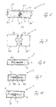
- Fig. 1 schematically shows the structure of a surface element 1 of, for example, rectangular shape, which is composed of a shell 2 of good heat conducting material, in particular metal, and a filling 3 of phase change material.
- the sheath 2 can for example consist of a hollow profile produced by extrusion or by roll deformation, which is closed at the ends. However, it can also be a hollow profile composed of U-shaped profiles, which is made tight at the connection edges with respect to the filling material of PCM
- Fig. 1 are embedded in the filled with phase change material 3 hollow section 2 heating or cooling lines 4, so that the surface element 1 is directly connected to the heating or cooling lines 4 via the PCM.
- the phase change material is below the predetermined, depending on the type of PCM switching temperature of, for example, 23 or 26 ° C in solid form, for example in powder or granular form, while it passes when heated above the switching temperature in the molten state and thus fixed by the phase into the liquid phase changes.
- PCM switching temperature for example, 23 or 26 ° C in solid form, for example in powder or granular form
- the tightness of the shell. 2 be designed for the tightness against the plastic capsules instead of a liquid.
- phase change materials are paraffin and sodium acetate.
- water could be used as PCM, but the switching temperature of water at 0 ° C is not in the desired working range by about 23 ° C.
- the phase change material liquefies when heat absorption above the switching temperature and solidifies again with release of heat below the Switching temperature, the high heat storage capacity of the phase change material can be advantageously used in space requirements for the room air conditioning, after in a relatively low mass of PCM, a relatively high heat energy can be stored
- this material can be integrated in a simple way in heating or cooling ceilings or in wall and floor heating systems, the PCM-filled surface elements can be directly connected to heating cables in rondleitcard, such as Fig. 1 shows, or indirectly via a heat conductive material between PCM and heating or cooling line
- Fig. 2 shows an embodiment in which a PCM-filled hollow section 1 or a plate 1 is arranged in heat-conducting connection with a concrete ceiling B, in the heating or cooling lines L are embedded.
- the plate 1 may be clad with a metal sheet 6, as is commonly used for ceiling panels.
- Fig. 2 is the surface element 1 or the PCM indirectly with the heating or cooling lines L in heat conductive connection.
- the heat storage capacity of, for example, 10 mm thick, filled with PCM plate 1 corresponds approximately to the heat storage capacity of about 30 cm thick concrete ceiling, the PCM can be switched faster by supplying heat or cooling, as provided with heating / cooling pipes concrete surface
- PCM-filled plates or hollow sections 1 are used in heat-conducting communication with a heating or cooling line, as well Fig. 3 shows.
- a line 4 preferably a copper line, with a round cross-section in a corresponding formed recess 21 of the metal shell 2 of the plate 1 used to increase the area of the heat-conductive contact with the shell 2.
- At least one heat-conducting web 2 2 may be formed within the plate 1, such as Fig. 4 shows, through which the heat transfer from the line 4 to the PCM and to the room to be conditioned facing side of the plate 1 and thus the distribution of heat over the surface of the plate is improved
- a heat transfer web 2.2 increases the reaction rate of the PCM or the heating - or cooling system
- a nickelleitsteg can also extend radially into the phase change material 3, as in Fig. 4 at 2 3 is indicated by dashed lines
- Fig. 4 reproduced cross-sectional profile of the shell 2 with Vietnameseleitsteg 2 2 may be formed for example as an extruded profile or as a roll-shaped profile, wherein the hollow profile is closed after filling with PCM at the ends so that no PCM can escape in the liquefied state
- Fig. 5 shows a further embodiment in which on the plate 1 with embedded in a recess of the sheath 2 line 4, a cover 5 is provided, through which the heat transfer from the line 4 to the upper surface of the sheath 2 is improved
- This cover 5 may consist of a correspondingly shaped metal sheet or of a flexible, well heat conductive cover sheet covering the line 4 and the top of the plate 1, such as Fig. 5 schematically shows.
- the plate 1 acts as varnishleitprofil between line 4 and panel 6
- the shape of the plate can be adapted to the requirements of the particular structure.
- the plate 1 can be designed as a strip or lamella or more band-shaped, when the surface element 1 serves as a heat conduction profile for a single line 4.
- the plate 1 according to the dimensions of Ceiling element or be formed in adjacent strips
- the surface element instead of a strip or lamellar shape of the surface element 1, another shape of the surface element serving as a heat conduction profile may be provided with PCM-filled surface element.
- the shell 2 may also be round or oval in cross-section, recesses being formed on the circumference for one or more heating elements. or cooling lines 4 may be provided.
- Fig. 6 schematically shows an embodiment in which two hollow profiles 20 and 20 'are each provided with a recess on the adjacent side surfaces to enclose a recorded in the wells line 4 over the entire surface.
- Fig. 7 shows an embodiment similar Fig. 6 , wherein the two hollow sections 20 and 20 'completely enclosing a line 4 at the contact surfaces have positive-locking elements 23 and 24, through which the two hollow profiles 20 and 20' pushed into each other during assembly or inserted into each other to produce a positive connection.
- Fig. 8 shows an embodiment with an approximately rectangular hollow cross section of a hollow profile 2, in which a cross-sectional flat heating or cooling line 40 is arranged to improve the heat distribution to the PCM in the hollow section 2.
- Fig. 9 shows an embodiment in which heat conduction surfaces 4.1 are formed on the line 4 at diametrically opposite points, which serve for better heat distribution over the volume of the phase change material 3.
- FIG. 10 shows an embodiment in which the PCM embedded heating or cooling line 4 is surrounded by a heat conducting profile 8 in order to improve the heat transfer and heat distribution to the PCM within the heat-conducting sheath 2.
- the heating or cooling line 4 or 40 can be arranged in a hollow profile 8, which in turn is contained in the filled with PCM 3 hollow section 2
- Fig. 10 is schematically represented the hollow section 8 by two adjacent sheet metal parts.
- the embedded in PCM heating or cooling lines 4 may have any cross-sectional shape and be surrounded in various ways with a beideleitprofil
- Fig. 11 shows a preferred arrangement in combination with a support plate 10, which may for example consist of plasterboard or a metal plate, including a perforated metal plate, on which rests the filled with PCM 3 hollow profile 2, wherein the heating or cooling line 4 within the hollow profile. 2 can run, like Fig. 1 shows, or may be in heat conductive connection with the sheath 2, as this 3 to 6
- a composite of the surface element 1 according to the invention with a carrier plate 10 can be provided in particular in the case of cooling and electric blankets or corresponding wall elements
- FIG. 12 shows such a composite arrangement between the surface element 1 and the support plate 10, wherein the heating or cooling line 4 is on the one hand to the support plate 10 in heat conductive connection and on the other hand with the shell 2 of the surface element 1, in this embodiment, a deeper recess than in Fig. 11 has to substantially completely accommodate the line cross-section.
- a configuration can also according to the surface elements Fig. 1 to 5 be provided.
- the two hollow profile 20 and 20 ' can by a in Fig. 6 It is also possible, however, to provide an adhesive connection to the contact surfaces 22 of the two hollow sections 20 and 20 ', as indicated by dashed lines
- the support plate 10 with the surface element 1 in FIGS. 11 and 12 be connected by an adhesive bond.
Landscapes
- Engineering & Computer Science (AREA)
- Mechanical Engineering (AREA)
- General Engineering & Computer Science (AREA)
- Thermal Sciences (AREA)
- Physics & Mathematics (AREA)
- Chemical & Material Sciences (AREA)
- Combustion & Propulsion (AREA)
- Architecture (AREA)
- Life Sciences & Earth Sciences (AREA)
- Sustainable Development (AREA)
- Civil Engineering (AREA)
- Structural Engineering (AREA)
- Building Environments (AREA)
Abstract
Flächenelement mit einer Wärme leitenden Hülle (2), die ein Phasenwechselmaterial (3) umgibt, wobei das Flächenelement (1) direkt oder indirekt mit einer Heiz- bzw Kühlleitung (L, 4, 40) in Wärme leitender Verbindung steht.
Description
- Die Erfindung betrifft den Aufbau eines Wärme leitenden Flächenelementes, beispielsweise einer Platte, die z. B. für eine Klimadecke verwendet werden kann.
- Es ist bekannt, das Wärmespeichervermögen von Betondecken für die Klimatisierung eines darunter liegenden Raumes zu nutzen, wobei in die Betondecke Heiz- bzw. Kühlleitungen eingegossen sind, um beispielsweise nachts die Betondecke zu kühlen, damit sie während der Nutzung des Raumes zur Kühlung eingesetzt werden kann. Hierbei werden zur Verkleidung der Betondecke Flächenelemente aus Metallblech eingesetzt, die in einer Wärme leitenden Verbindung mit der Betondecke stehen, um die in der Betondecke gespeicherte Wärme auf den Raum zu übertragen und umgekehrt.
- Der Erfindung liegt die Aufgabe zugrunde, ein Flächenelement bereitzustellen, mittels dem die Wärmespeicherkapazität und die Anpassung an die Erfordernisse der Klimatisierung eines Raumes verbessert werden.
- Erfindungsgemäß wird ein Flächenelement aus einer mit einem Phasenwechselmaterial (PCM) gefüllten, Wärme leitenden Hülle vorgesehen, wobei das Flächenelement direkt oder indirekt mit einer Heiz- bzw. Kühlleitung in Wärme leitender Verbindung steht.
- Durch die Verwendung eines Phasenwechselmaterials kann die Anpassung an die erforderliche Heizung bzw. Kühlung eines Raumes gezielter vorgenommen werden als durch in Beton eingegossene Leitungen Zusätzlich kann die Wärmespeicherkapazität gegenüber Beton wesentlich verbessert werden. Insgesamt kann ein erfindungsgemäßes Flächenelement in vielfältiger Weise als Wärmeleitelement eingesetzt werden
- Die Erfindung wird beispielsweise anhand der Zeichnung näher erläutert Es zeigen
- Fig. 1
- einen Querschnitt durch ein plattenförmiges Flächenelement, das mit Phasenwechselmaterial gefüllt ist, in dem Heiz- bzw. Kühlleitungen eingebettet sind,
- Fig. 2
- eine Anordnung des Flächenelementes an einer Betondecke,
- Fig. 3
- schematisch ein Flächenelement in Wärmeleitkontakt mit einer Heiz- bzw. Kühlleitung,
- Fig. 4
- einen Querschnitt durch eine Ausführungsform eines Flächenelementes,
- Fig 5
- im Querschnitt schematisch eine weitere Ausführungsform eines Flächenelementes,
- Fig 6
- eine Ausgestaltung mit zwei Hohlprofilen,
- Fig. 7
- eine abgewandelte Ausführungsform mit zwei Hohlprofilen,
- Fig. 8
- schematisch eine Querschnittsansicht mit einem flachen Leitungsquerschnitt,
- Fig. 9
- eine Ausführungsabwandlung mit Wärmeleitstegen an der Leitung,
- Fig. 10
- schematisch eine Ausführungsform im Querschnitt mit einer von einem Wärmeleitprofil umgebenen Leitung,
- Fig. 11
- eine Verbundanordnung mit einer Trägerplatte, und
- Fig. 12
- eine abgewandelte Ausführungsform der Anordnung nach
Fig. 11 . -
Fig 1 zeigt schematisch den Aufbau eines Flächenelementes 1 von beispielsweise rechteckiger Form, das aus einer Hülle 2 aus gut Wärme leitendem Material, insbesondere Metall, und einer Füllung 3 aus Phasenwechselmaterial aufgebaut ist. Die Hülle 2 kann beispielsweise aus einem durch Strangpressen oder durch Rollverformung hergestellten Hohlprofil bestehen, das an den Enden geschlossen ist Es kann aber auch ein aus im Querschnitt U-förmigen Profilen zusammengesetztes Hohlprofil sein, das an den Verbindungsrändern gegenüber dem Füllmaterial aus PCM dicht ausgebildet ist - In
Fig 1 sind in dem mit Phasenwechselmaterial 3 gefüllten Hohlprofil 2 Heiz- bzw. Kühlleitungen 4 eingebettet, sodass das Flächenelement 1 direkt mit den Heiz- bzw. Kühlleitungen 4 über das PCM in Verbindung steht. - Das Phasenwechselmaterial liegt unterhalb der vorgegebenen, von der Art des PCM abhändigen Schalttemperatur von beispielsweise 23 oder 26° C in fester Form vor, beispielsweise in Pulver- oder Granulatform, während es bei Erwärmung über die Schalttemperatur in schmelzflüssigen Zustand übergeht und somit von der Phase fest in die Phase flüssig wechselt. Anstelle von Pulver bzw granulatförmigem PCM kann auch ein in Kunststoffkapseln eingeschlossenes PCM verwendet werden, sodass sich im verflüssigten Zustand des PCM keine Veränderung hinsichtlich Handhabung der Füllung gegenüber dem Ausgangszustand unterhalb der Schalttemperatur ergibt. Bei einer solchen Art der Füllung 3 kann die Dichtigkeit der Hülle 2 auf die Dichtigkeit gegenüber den Kunststoffkapseln anstelle einer Flüssigkeit ausgelegt werden.
- Bekannte Phasenwechselmaterialien sind Paraffin und Natriumacetat. An sich könnte auch Wasser als PCM verwendet werden, jedoch liegt die Schalttemperatur von Wasser bei 0° C nicht in dem gewünschten Arbeitsbereich um etwa 23° C. Das Phasenwechselmaterial verflüssigt sich bei Wärmeaufnahme oberhalb der Schalttemperatur und verfestigt sich wieder unter Abgabe von Wärme unterhalb der Schalttemperatur, wobei das hohe Wärmespeichervermögen des Phasenwechselmaterials hinsichtlich Platzbedarf vorteilhaft für die Raumklimatisierung ausgenutzt werden kann, nachdem in einer relativ geringen Masse an PCM eine relativ hohe Wärmeenergie gespeichert werden kann
- Durch die Umhüllung des PCM in Platten- oder Lamellenform, kann dieses Material in einfächer Weise in Heiz- bzw. Kühldecken oder auch in Wand- und Fußbodenheizungen integriert werden, wobei die mit PCM gefüllten Flächenelemente direkt mit Heizleitungen in Wärmeleitkontakt stehen können, wie
Fig 1 zeigt, oder auch indirekt über ein Wärme leitendes Material zwischen PCM und Heiz- bzw Kühlleitung -
Fig 2 zeigt ein Ausführungsbeispiel, bei dem ein mit PCM gefülltes Hohlprofil 1 oder eine Platte 1 in Wärme leitender Verbindung mit einer Betondecke B angeordnet ist, in der Heiz- bzw. Kühlleitungen L eingebettet sind. Hierbei kann auf der Sichtseite die Platte 1 mit einem Metallblech 6 verkleidet sein, wie es üblicherweise für Deckenverkleidungen verwendet wird. Bei dieser Anordnung nachFig. 2 steht das Flächenelement 1 bzw das PCM indirekt mit den Heiz- bzw Kühlleitungen L in Wärme leitender Verbindung. - Das Wärmespeichervermögen einer beispielsweise 10 mm dicken, mit PCM gefüllten Platte 1 entspricht etwa dem Wärmespeichervermögen einer ca 30 cm dicken Betondecke, wobei das PCM durch Wärmezufuhr oder Kühlung schneller umgeschaltet werden kann, als die mit Heiz-/Kühlleitungen versehene Betondecke
- Vorzugsweise weiden mit PCM gefüllte Platten oder Hohlprofile 1 in Wärme leitender Verbindung mit einer Heiz- bzw. Kühlleitung verwendet, wie dies
Fig. 3 zeigt. Hierbei ist eine Leitung 4, vorzugsweise eine Kupferleitung, mit rundem Querschnitt in eine entsprechend geformte Vertiefung 21 der Metallhülle 2 der Platte 1 eingesetzt, um die Fläche des Wärme leitenden Kontakts mit der Hülle 2 zu vergrößern. - Zur Verbesserung der Wärmeverteilung von der Leitung 4 über die Wärme leitende Hülle 2 auf das in der Platte 1 verteilte PCM kann innerhalb der Platte 1 wenigstens ein Wärme leitender Steg 2 2 ausgebildet sein, wie
Fig. 4 zeigt, durch den die Wärmeübertragung von der Leitung 4 auf das PCM und die dem zu klimatisierenden Raum zugewandte Seite der Platte 1 und damit die Verteilung der Wärme über die Fläche der Platte verbessert wird Ein solcher Wärmeleitsteg 2.2 erhöht die Reaktionsgeschwindigkeit des PCM bzw. des Heiz- oder Kühlsystems Hierzu kann sich ein Wärmeleitsteg auch strahlenförmig in das Phasenwechselmaterial 3 erstrecken, wie dies inFig. 4 bei 2 3 durch gestrichelte Linien angedeutet ist - Das in
Fig 4 wiedergegebene Querschnittsprofil der Hülle 2 mit Wärmeleitsteg 2 2 kann beispielsweise als Strangpressprofil oder als rollverformtes Profil ausgebildet sein, wobei das Hohlprofil nach dem Füllen mit PCM an den Enden so verschlossen wird, dass kein PCM im verflüssigten Zustand entweichen kann -
Fig. 5 zeigt eine weitere Ausführungsform, bei der auf der Platte 1 mit in einer Vertiefung der Hülle 2 eingebetteter Leitung 4 eine Abdeckung 5 vorgesehen ist, durch die der Wärmeübergang von der Leitung 4 auf die obere Fläche der Hülle 2. verbessert wird - Diese Abdeckung 5 kann aus einem entsprechend geformten Metallblech oder auch aus einer flexiblen, gut Wärme leitenden Abdeckbahn bestehen, die die Leitung 4 und die Oberseite der Platte 1 abdeckt, wie
Fig. 5 schematisch zeigt. - Bei Verwendung der mit PCM gefüllten Platte 1 in Verbindung mit einer gut Wärme leitenden Verkleidung 6 auf der Sichtseite, wie sie in
Fig 2 gezeigt ist, wirkt die Platte 1 als Wärmeleitprofil zwischen Leitung 4 und Verkleidung 6 Entsprechend kann die Form der Platte an die Erfordernisse des jeweiligen Aufbaus angepasst sein. Beispielsweise kann die Platte 1 als Leiste bzw. Lamelle oder mehr bandförmig gestaltet sein, wenn das Flächenelement 1 als Wärmeleitprofil für eine einzelne Leitung 4 dient In Verbindung mit einem Heiz- bzw. Kühlregister mit mehreren nebeneinander liegenden Leitungen kann die Platte 1 entsprechend den Abmessungen des Deckenelementes oder auch in nebeneinander liegenden Streifen ausgebildet sein - Anstelle einer Streifen- oder Lamellenform des Flächenelementes 1 kann auch eine andere Form des als Wärmeleitprofil dienenden, mit PCM gefüllten Flächenelementes vorgesehen werden Beispielsweise kann die Hülle 2 im Querschnitt auch rund oder oval gestaltet sein, wobei auf dem Umfang Vertiefungen für eine oder mehrere Heiz- bzw. Kühlleitungen 4 vorgesehen sein können.
-
Fig. 6 zeigt schematisch eine Ausführungsform, bei der zwei Hohlprofile 20 und 20' mit jeweils einer Vertiefung an den aneinander liegenden Seitenflächen vorgesehen sind, um eine in die Vertiefungen aufgenommene Leitung 4 ganzflächig zu umschließen. Hierdurch wird der Wärmeübergang zwischen der Leitung 4 und dem Phasenwechselmaterial 3 bzw. die Wärmeverteilung über das PCM verbessert, wobei die beiderseits der Vertiefungen 21 vorhandenen Stege 22 der Hohlprofile 20 und 20' zugleich als Wärmeleitprofile dienen -
Fig. 7 zeigt eine Ausgestaltung ähnlichFig. 6 , wobei die beiden eine Leitung 4 vollständig umschließenden Hohlprofile 20 und 20' an den Kontaktflächen formschlüssige Elemente 23 und 24 aufweisen, durch die die beiden Hohlprofile 20 und 20' bei der Montage ineinander geschoben oder ineinander gesteckt werden können, um eine formschlüssige Verbindung herzustellen. -
Fig. 8 zeigt ein Ausführungsbeispiel mit einem etwa rechteckigen Hohlquerschnitt eines Hohlprofils 2, in dem eine im Querschnitt flache Heiz- bzw. Kühlleitung 40 angeordnet ist, um die Wärmeverteilung auf das PCM in dem Hohlprofil 2 zu verbessern. -
Fig. 9 zeigt ein Ausführungsbeispiel, bei dem an der Leitung 4 an diametral gegenüber liegenden Stellen Wärmeleitflächen 4.1 angeformt sind, die zur besseren Wärmeverteilung über das Volumen des Phasenwechselmaterials 3 dienen. -
Fig 10 zeigt eine Ausführungsform, bei der die in PCM eingebettete Heiz- bzw. Kühlleitung 4 von einem Warmeleitprofil 8 umgeben ist, um die Wärmeübertragung und Wärmeverteilung auf das PCM innerhalb der Wärme leitenden Hülle 2 zu verbessern. Mit anderen Worten kann die Heiz- bzw Kühlleitung 4 bzw 40 in einem Hohlprofil 8 angeordnet werden, das wiederum in dem mit PCM 3 gefüllten Hohlprofil 2 enthalten ist InFig. 10 ist schematisch das Hohlprofil 8 durch zwei aneinander liegende Blechteile wiedergegeben. - Die in PCM eingebetteten Heiz- bzw. Kühlleitungen 4 können eine beliebige Querschnittsform haben und in verschiedener Weise auch mit einem Wärmeleitprofil umgeben sein
- Die in den
Fig. 3 bis 10 wiedergegebenen Flächenelemente bzw Hohlprofile können als Heiz- bzw Kühlelemente bei einem Heiz- bzw Kühlsystem verwendet werden.Fig. 11 zeigt eine bevorzugte Anordnung im Verbund mit einer Trägerplatte 10, die beispielsweise aus Gipskarton oder einer Metallplatte, auch einer gelochten Metallplatte, bestehen kann, auf der das mit PCM 3 gefüllte Hohlprofil 2 aufliegt, wobei die Heiz- bzw. Kühlleitung 4 innerhalb des Hohlprofils 2 verlaufen kann, wieFig 1 zeigt, oder in Wärme leitender Verbindung mit der Hülle 2 stehen kann, wie diesFig 3 bis 6 zeigen Ein solcher Verbund des erfindungsgemä-βen Flächenelementes 1 mit einer Trägerplatte 10 kann insbesondere bei Kühl- und Heizdecken oder entsprechenden Wandelementen vorgesehen werden -
Fig 12 zeigt eine solche Verbundanordnung zwischen Flächenelement 1 und Trägerplatte 10, wobei die Heiz- bzw. Kühlleitung 4 einerseits mit der Trägerplatte 10 in Wärme leitender Verbindung steht und andererseits mit der Hülle 2 des Flächenelementes 1, das bei diesem Ausführungsbeispiel eine tiefere Ausnehmung als inFig. 11 aufweist, um den Leitungsquerschnitt im Wesentlichen vollständig aufzunehmen. Eine solche Ausgestaltung kann auch bei den Flächenelementen nach denFig. 1 bis 5 vorgesehen werden. - Die beiden Hohlprofil 20 und 20' können durch einen in
Fig. 6 durch gestrichelte Linien angedeuteten Bügel 11 in dichter Anlage aneinander gehalten werden Es ist aber auch möglich, an den Anlageflächen 22 der beiden Hohlprofile 20 und 20' eine Klebeverbindung vorzusehen - In gleicher Weise kann die Trägerplatte 10 mit dem Flächenelement 1 in
Fig. 11 und 12 durch eine Klebeverbindung miteinander verbunden sein.
Claims (11)
- Flächenelement mit einer Wärme leitenden Hülle (2), die ein Phasenwechselmaterial (3) umgibt,
wobei das Flächenelement (1) direkt oder indirekt mit einer Heiz- bzw. Kühlleitung (L, 4, 40) in Wärme leitender Verbindung steht. - Flächenelement nach Anspruch 1, wobei die Heiz- bzw. Kühlleitung (4, 40) in dem Phasenwechselmaterial (3) innerhalb der Hülle (2) eingebettet ist, sodass sich eine direkte Wärme leitende Verbindung zwischen Heiz- bzw. Kühlleitung (4, 40) und Phasenwechselmaterial ergibt.
- Flächenelement nach Anspruch 1, wobei in der Hülle (2) eine Vertiefung (2.1, 21) zur Aufnahme einer Leitung (4) vorgesehen ist, sodass die Heiz- bzw. Kühlleitung (4) indirekt über die Wärme leitende Hülle (2) mit dem Phasenwechselmaterial in Wärme leitender Verbindung steht.
- Flächenelement nach Anspruch 3, wobei die wenigstens auf einem Teil ihres Umfangs in der Hülle (2) eingebettete Leitung (4) mit einer Abdeckung (5) versehen ist, die aus Wärme leitendem Material besteht und sich wenigstens teilweise über die Fläche der Hülle (2) erstreckt.
- Flächenelement nach einem der vorhergehenden Ansprüche, wobei innerhalb der Hülle (2) wenigstens ein Wärmeleitsteg (2.2, 2.3) zur Wärmeverteilung innerhalb des PCM vorgesehen ist
- Flächenelement nach Anspruch 2, wobei die Heiz- bzw. Kühlleitung (4, 40) mit Wärmeleitstegen (4.1) versehen ist, die sich in das Phasenwechselmaterial (3) erstrecken.
- Flächenelement nach Anspruch 3, wobei mit einer Vertiefung (21) als Aufnahme einer Leitung (4) versehene Hüllen (2) bzw. Hohlprofile (20, 20') so aneinander gesetzt sind, dass die beiden Hohlprofile (20, 20') die Leitung (4) vollständig umschließen.
- Flächenelement nach Anspruch 7, wobei die beiden Hohlprofile (20, 20') an den aneinander liegenden Flächen mit Profilelementen (23, 24) für eine formschlüssige Verbindung versehen sind.
- Flächenelement nach einem der vorhergehenden Ansprüche, wobei das Flächenelement (1) mit einer Trägerplatte (10) einen Verbund bildet und mit dieser in Wärme leitender Verbindung steht.
- Flächenelement mit einer Wärme leitenden Hülle (2), die ein Phasenwechselmateiial (3) umgibt, wobei das Flächenelement (1) an einem Abschnitt eines Massivbaukörpers (B) anliegt, in dem Heiz- bzw. Kühlleitungen (L) angeordnet sind
- Flächenelement nach einem der vorhergehenden Ansprüche, wobei das Flächenelement (1) mit einer Wärme leitenden Verkleidung (6) versehen ist.
Applications Claiming Priority (1)
| Application Number | Priority Date | Filing Date | Title |
|---|---|---|---|
| DE202010016878U DE202010016878U1 (de) | 2010-12-21 | 2010-12-21 | Aufbau eines Wärme leitenden Flächenelementes |
Publications (1)
| Publication Number | Publication Date |
|---|---|
| EP2468977A1 true EP2468977A1 (de) | 2012-06-27 |
Family
ID=45319004
Family Applications (1)
| Application Number | Title | Priority Date | Filing Date |
|---|---|---|---|
| EP11193466A Withdrawn EP2468977A1 (de) | 2010-12-21 | 2011-12-14 | Wärmeleitendes Flächenelement |
Country Status (2)
| Country | Link |
|---|---|
| EP (1) | EP2468977A1 (de) |
| DE (1) | DE202010016878U1 (de) |
Cited By (4)
| Publication number | Priority date | Publication date | Assignee | Title |
|---|---|---|---|---|
| DE102013200587A1 (de) * | 2013-01-16 | 2014-07-17 | Caverion Deutschland GmbH | Luftauslass zur Konditionierung von Raumluft eines Raumes sowie zugehöriges Verfahren |
| US10294861B2 (en) | 2015-01-26 | 2019-05-21 | Trent University | Compressed gas energy storage system |
| WO2021078437A1 (de) * | 2019-10-25 | 2021-04-29 | Thomas Piller | Wärmespeichereinheit |
| DE102022106951A1 (de) | 2022-03-24 | 2023-09-28 | Thomas Piller | Wärmespeichereinheit |
Families Citing this family (8)
| Publication number | Priority date | Publication date | Assignee | Title |
|---|---|---|---|---|
| ITTO20120792A1 (it) * | 2012-09-14 | 2014-03-15 | Lorenzo Pezzi | Condizionatore d'aria e d'ambiente con accumulatore termico a calore latente |
| FR2998907B1 (fr) * | 2012-12-04 | 2016-02-26 | Enia Arch | Structure modulaire de cloison pour la delimitation de poste de travail notamment |
| DE202013100848U1 (de) * | 2013-02-27 | 2014-03-10 | Yit Germany Gmbh | Vorrichtung zur Temperierung eines Raumes |
| DE102013102990A1 (de) * | 2013-03-22 | 2014-09-25 | Armin Bühler | Wand- oder Deckenverkleidung |
| CN108291783A (zh) | 2015-11-30 | 2018-07-17 | 英沃斯私人有限公司 | 加热和冷却空间 |
| FR3058779B1 (fr) * | 2016-11-17 | 2019-10-18 | Placoplatre | Panneau de construction chauffant |
| AT16106U1 (de) * | 2018-04-13 | 2019-01-15 | Friedrich Fahrnberger Ffk Kommunikationsdesign & Werbeagentur | Paneele |
| CN115233859B (zh) * | 2022-06-24 | 2023-10-03 | 哈尔滨工业大学 | 一种低能耗相变储能连接件 |
Citations (5)
| Publication number | Priority date | Publication date | Assignee | Title |
|---|---|---|---|---|
| DE102004017021A1 (de) * | 2004-04-02 | 2005-10-20 | Ardex Gmbh | Latentwärmespeicher |
| DE102006029597A1 (de) * | 2005-06-28 | 2007-01-25 | Harry Schmitz | Klimadecke |
| DE202006007617U1 (de) * | 2006-05-11 | 2007-06-21 | M+W Zander Gebäudetechnik GmbH | Vorrichtung zum Temperieren eines Raumes |
| DE202007012999U1 (de) * | 2007-09-17 | 2008-03-27 | Ilkazell Isoliertechnik Gmbh Zwickau | Vorgefertigtes Verbundplattenelement zum Klimatisieren von Räumen |
| DE202010010566U1 (de) * | 2010-07-23 | 2010-10-14 | Gib Gesellschaft Für Innovative Bautechnologie Mbh | Deckenaufbau |
-
2010
- 2010-12-21 DE DE202010016878U patent/DE202010016878U1/de not_active Expired - Lifetime
-
2011
- 2011-12-14 EP EP11193466A patent/EP2468977A1/de not_active Withdrawn
Patent Citations (5)
| Publication number | Priority date | Publication date | Assignee | Title |
|---|---|---|---|---|
| DE102004017021A1 (de) * | 2004-04-02 | 2005-10-20 | Ardex Gmbh | Latentwärmespeicher |
| DE102006029597A1 (de) * | 2005-06-28 | 2007-01-25 | Harry Schmitz | Klimadecke |
| DE202006007617U1 (de) * | 2006-05-11 | 2007-06-21 | M+W Zander Gebäudetechnik GmbH | Vorrichtung zum Temperieren eines Raumes |
| DE202007012999U1 (de) * | 2007-09-17 | 2008-03-27 | Ilkazell Isoliertechnik Gmbh Zwickau | Vorgefertigtes Verbundplattenelement zum Klimatisieren von Räumen |
| DE202010010566U1 (de) * | 2010-07-23 | 2010-10-14 | Gib Gesellschaft Für Innovative Bautechnologie Mbh | Deckenaufbau |
Cited By (5)
| Publication number | Priority date | Publication date | Assignee | Title |
|---|---|---|---|---|
| DE102013200587A1 (de) * | 2013-01-16 | 2014-07-17 | Caverion Deutschland GmbH | Luftauslass zur Konditionierung von Raumluft eines Raumes sowie zugehöriges Verfahren |
| US10294861B2 (en) | 2015-01-26 | 2019-05-21 | Trent University | Compressed gas energy storage system |
| WO2021078437A1 (de) * | 2019-10-25 | 2021-04-29 | Thomas Piller | Wärmespeichereinheit |
| DE102022106951A1 (de) | 2022-03-24 | 2023-09-28 | Thomas Piller | Wärmespeichereinheit |
| EP4257909A1 (de) | 2022-03-24 | 2023-10-11 | Thomas Piller | Wärmespeichereinheit |
Also Published As
| Publication number | Publication date |
|---|---|
| DE202010016878U1 (de) | 2012-03-22 |
Similar Documents
| Publication | Publication Date | Title |
|---|---|---|
| EP2468977A1 (de) | Wärmeleitendes Flächenelement | |
| EP0371268B1 (de) | Flächenelement für einen beheizbaren Hohlraumboden | |
| EP2631966B1 (de) | Fluiddurchströmtes Temperierelement und Traktionsbatterie mit gehäuseintegriertem fluiddurchströmten Temperierelement | |
| EP2751512A1 (de) | Wärmeleitplatte, insbesondere zum kühlen oder heizen eines gebäudes | |
| DE202009003205U1 (de) | Plattenelement für ein Deckenheizungs- und/oder Kühlungselement | |
| EP1688672B1 (de) | Unterkonstruktion | |
| EP0859200B1 (de) | Heizpaneel | |
| WO2014000852A1 (de) | Wärmemanagementsystem | |
| DE202006011151U1 (de) | Plattenförmige Vorrichtung zur Aufnahme von Leitungen | |
| WO2007042331A1 (de) | Wärmetauscherplatte | |
| EP2565338A1 (de) | Plattenförmiges Element für Heizungs- oder Kühlsysteme | |
| EP2667102B1 (de) | Verbundbauelement für eine Fußboden-, Wand- oder Deckenklimatisierungsvorrichtung eines Gebäudes | |
| WO2010099861A1 (de) | Klimadecke | |
| DE20210714U1 (de) | Holz-Beton-Verbundelement mit integriertem Klimaelement | |
| DE102005027495A1 (de) | Struktur in einem Bauwerk | |
| EP2667100B1 (de) | Verbundbauelement für eine Fußboden-, Wand- oder Deckenklimatisierungsvorrichtung eines Gebäudes sowie Verfahren zu seiner Herstellung | |
| DE2853233A1 (de) | Heizrohr | |
| DE2926685A1 (de) | Vorgefertigtes bodenelement fuer fussbodenheizungen | |
| DE2853234A1 (de) | Heizrohr | |
| DE9314110U1 (de) | Plattenförmiger Wärmetauscher | |
| DE202011050169U1 (de) | Wärmeübertragungsanordnung | |
| WO2024156715A1 (de) | Profil, profilanordnung und temperierungssystem | |
| DE202009013100U1 (de) | Bausatz für eine Temperiervorrichtung | |
| CH707243A1 (de) | Deckenelement für eine Heiz- oder Kühldecke sowie Heiz- oder Kühldecke. | |
| DE202023102668U1 (de) | Flächentemperiersystem |
Legal Events
| Date | Code | Title | Description |
|---|---|---|---|
| AK | Designated contracting states |
Kind code of ref document: A1 Designated state(s): AL AT BE BG CH CY CZ DE DK EE ES FI FR GB GR HR HU IE IS IT LI LT LU LV MC MK MT NL NO PL PT RO RS SE SI SK SM TR |
|
| AX | Request for extension of the european patent |
Extension state: BA ME |
|
| PUAI | Public reference made under article 153(3) epc to a published international application that has entered the european phase |
Free format text: ORIGINAL CODE: 0009012 |
|
| STAA | Information on the status of an ep patent application or granted ep patent |
Free format text: STATUS: THE APPLICATION IS DEEMED TO BE WITHDRAWN |
|
| 18D | Application deemed to be withdrawn |
Effective date: 20130103 |