EP2468972A2 - Trennwand mit einer Vorder- und Rückwand, die an einem Rahmen mittels Klettverschlüssen befestigt ist - Google Patents
Trennwand mit einer Vorder- und Rückwand, die an einem Rahmen mittels Klettverschlüssen befestigt ist Download PDFInfo
- Publication number
- EP2468972A2 EP2468972A2 EP11168404A EP11168404A EP2468972A2 EP 2468972 A2 EP2468972 A2 EP 2468972A2 EP 11168404 A EP11168404 A EP 11168404A EP 11168404 A EP11168404 A EP 11168404A EP 2468972 A2 EP2468972 A2 EP 2468972A2
- Authority
- EP
- European Patent Office
- Prior art keywords
- panel
- partition
- rectangular frame
- support pillar
- partition panel
- Prior art date
- Legal status (The legal status is an assumption and is not a legal conclusion. Google has not performed a legal analysis and makes no representation as to the accuracy of the status listed.)
- Withdrawn
Links
Images


Classifications
-
- E—FIXED CONSTRUCTIONS
- E04—BUILDING
- E04B—GENERAL BUILDING CONSTRUCTIONS; WALLS, e.g. PARTITIONS; ROOFS; FLOORS; CEILINGS; INSULATION OR OTHER PROTECTION OF BUILDINGS
- E04B2/00—Walls, e.g. partitions, for buildings; Wall construction with regard to insulation; Connections specially adapted to walls
- E04B2/74—Removable non-load-bearing partitions; Partitions with a free upper edge
- E04B2/7407—Removable non-load-bearing partitions; Partitions with a free upper edge assembled using frames with infill panels or coverings only; made-up of panels and a support structure incorporating posts
- E04B2/7416—Removable non-load-bearing partitions; Partitions with a free upper edge assembled using frames with infill panels or coverings only; made-up of panels and a support structure incorporating posts with free upper edge, e.g. for use as office space dividers
- E04B2/7433—Removable non-load-bearing partitions; Partitions with a free upper edge assembled using frames with infill panels or coverings only; made-up of panels and a support structure incorporating posts with free upper edge, e.g. for use as office space dividers with panels and support posts
- E04B2/7438—Removable non-load-bearing partitions; Partitions with a free upper edge assembled using frames with infill panels or coverings only; made-up of panels and a support structure incorporating posts with free upper edge, e.g. for use as office space dividers with panels and support posts with adjustable angular connection of panels to posts
- E04B2/744—Removable non-load-bearing partitions; Partitions with a free upper edge assembled using frames with infill panels or coverings only; made-up of panels and a support structure incorporating posts with free upper edge, e.g. for use as office space dividers with panels and support posts with adjustable angular connection of panels to posts using angularly-spaced longitudinal grooves of the posts
-
- E—FIXED CONSTRUCTIONS
- E04—BUILDING
- E04H—BUILDINGS OR LIKE STRUCTURES FOR PARTICULAR PURPOSES; SWIMMING OR SPLASH BATHS OR POOLS; MASTS; FENCING; TENTS OR CANOPIES, IN GENERAL
- E04H1/00—Buildings or groups of buildings for dwelling or office purposes; General layout, e.g. modular co-ordination or staggered storeys
- E04H1/12—Small buildings or other erections for limited occupation, erected in the open air or arranged in buildings, e.g. kiosks, waiting shelters for bus stops or for filling stations, roofs for railway platforms, watchmen's huts or dressing cubicles
- E04H1/1272—Exhibition stands
-
- E—FIXED CONSTRUCTIONS
- E04—BUILDING
- E04B—GENERAL BUILDING CONSTRUCTIONS; WALLS, e.g. PARTITIONS; ROOFS; FLOORS; CEILINGS; INSULATION OR OTHER PROTECTION OF BUILDINGS
- E04B2/00—Walls, e.g. partitions, for buildings; Wall construction with regard to insulation; Connections specially adapted to walls
- E04B2/74—Removable non-load-bearing partitions; Partitions with a free upper edge
- E04B2/7407—Removable non-load-bearing partitions; Partitions with a free upper edge assembled using frames with infill panels or coverings only; made-up of panels and a support structure incorporating posts
- E04B2/7416—Removable non-load-bearing partitions; Partitions with a free upper edge assembled using frames with infill panels or coverings only; made-up of panels and a support structure incorporating posts with free upper edge, e.g. for use as office space dividers
- E04B2002/7418—Accessories supported on the free upper edge, e.g. auxiliary panels, noise abatement devices
Definitions
- the present Invention relates to a partition panel, a panel structure and a connection structure of panels, and more particularly to a partition panel, a panel structure and a connection structure, which allow easy change of decoration and design without producing and preparing a plurality of panels.
- partition panels obtained by painting the surface of plywood and attaching fabrics or decoration sheets thereto is used to construct a booth using nails or the like.
- the partition panels are often scrapped after use.
- a booth structure that is constructed in a way that two rectangular thin frame panels made by painting their surfaces and attaching fabrics or decoration sheets thereto are overlapped with a gap so that metal members with concave sections are inserted to four peripheries thereof and fixed by metal fittings to make partition panels, then a double-sided adhesion tape or a Hook-and-Loop fastener is fixed to the concave portion of the partition panels so that a plurality of partition panels is fitted by insertion to a protrusion of a support pillar, and bars with a " ⁇ "-shaped section are inserted to upper and lower ends of the partition panels to improve its appearance and reinforce the partition panels in constructing a booth so that the partition panels may be assembled and dissembled in a simple way (Patent Literature 1).
- a double-sided adhesion tape or a Hook-and-Loop fastener is used for fixing the partition panel to the support pillar, and further the upper and lower bars with a " ⁇ "-shaped section are inserted to the upper and lower ends of the partition panel so that the partition panel may keep its standing state.
- the partition panel may fall down.
- the support pillar protrudes from the surface of the panel at its joint portion, and thus it is difficult to use the partition panel as a wide and flat panel surface.
- the Inventors of the present application proposed the connecting structure in which the bottom surface portion of side groove of the partition panel and the support pillar are magnetically attached with a magnet board, and also a connecting pillar portion of a connector is put into an upper opening of the support pillar and an insertion pin of the connector is put into a pin insertion hole of the reinforcing component located at an upper edge portion of the partition panel to connect the support pillar with the partition panel.
- the partition panels may be simply assembled and dissembled and have high strength so that the partition panels do not suddenly fall down by impact, and it is possible to use the partition panel as a wide and flat panel surface (Patent Literature 2).
- An object of the present Invention is to provide a partition panel of which the decoration or design may be exchanged and be carried in a simple way.
- a partition panel including a rectangular frame and thin side panels at both sides thereof, wherein the rectangular frame is configured by connecting horizontal bars at least between upper and lower ends of right and left vertical bars; one of Hook-and-Loop fasteners, which is manufactured to have a width with so coupling force as the thin side panel is not broken when being separated, is fixed to the panel attachment surface of the vertical bars and the horizontal bars of the rectangular frame with a continuous or discontinuous shape corresponding to the outer shape of the thin side panel; the other of the Hook-and-Loop fasteners is fixed to the rear surface of the thin side panel with a continuous or discontinuous shape corresponding to the outer shape of the thin side panel; and Hook-and-Loop fasteners are coupled, thereby the side panel is detachably attached to panel attachment surfaces of the vertical bars and the horizontal bars of the rectangular frame.
- the rectangular frame and the thin side panel are detachably attached by the securing of Hook-and-Loop fasteners.
- the thin side panel may be attached to or detached from the rectangular frame and the side panel itself is thin and lightweight comparison to the partition panel.
- the partition panel may be produced and carried at a low cost, thereby allowing great cost reduction.
- the coupling force of Hook-and-Loop fastener may be controlled by changing its width.
- the side panel is thin and lightweight, if the Hook-and-Loop fastener has too strong a coupling force, the thin side panel may be broken when being separated, though the thin side panel may be firmly attached to the rectangular frame.
- the Hook-and-Loop fastener has a width that ensures so coupling force without breaking the side panel when being separated.
- the strength of the partition panel may be deficient depending on the size or construction of booth that is constructed at an exhibition hall.
- a brace-shaped reinforcing bar may be fixed between the vertical bars and/or the horizontal bars of the rectangular frame to increase the strength thereof.
- the rectangular frame may be firmly fixed by using nails or the like in a state that the vertical bars and the horizontal bars are assembled into a rectangular shape.
- the partition panel when configured to be assembled and dissembled, the partition panel may be dissembled when transporting and then carried in a compact size, which ensures a simple transporting work and thus further reduces the transporting cost.
- the vertical bars and the horizontal bars may be detachably connected each other so that the rectangular frame may be dissembled into the vertical bars and the horizontal bars and then stored.
- grooves may be formed in the right and left sides and upper periphery of the partition panel over the entire lengths by attaching the rectangular frame and the side panel so that the right and left vertical bars are at locations deviated inwards from the side periphery of the thin side panel and the upper horizontal bars are at locations deviated downwards from the upper end periphery of the thin side panel.
- the support pillar for connecting adjacent partition panels configures a sectional appearance corresponding to the groove in the partition panel
- a magnet board is fixed to any one of the side of the support pillar or the bottom of the side groove of the partition panel, and a magnet board or metal board magnetically attached to the magnet board is fixed to the other one.
- the support pillar may be made of metal material that allows magnetic attachment.
- a reinforcing component with a concaved section having a pin inserting hole may be inserted into at least an edge in the upper groove of the partition panel to form the inserting hole in at least upper end among the upper and lower ends of the support pillar
- a connecting component for connecting the support pillar to the partition panel may include a connecting plate portion inserted into the upper groove of the partition panel, a connecting pillar portion fixed to the connecting plate portion and inserted into the upper end inserting hole of the support pillar, and an inserting pin fixed to the connecting plate portion and inserted into the pin inserting hole of the reinforcing component.
- the panel structure disclosed in the Patent Literature 2 may be limited only an example of the connection between the support pillar having a rectangular section and the partition panel having a groove formed in a side thereof, it is impossible to connect the panel structure of Octanorm SystemTM which connects the support pillar and the partition panel or its partition panel by forming a dovetail groove in a length direction of the support pillar and then inserting the connecting component at the side of the partition panel into the dovetail groove.
- a connecting structure panels for connecting a first panel structure and a second panel structure; wherein the first panel structure includes a partition panel and a first support pillar, the partition panel comprises a rectangular frame and the thin side panels at both sides thereof; the rectangular frame is configured by connecting horizontal bars at least between upper and lower ends of right and left vertical bars; one of Hook-and-Loop fasteners, which is manufactured to have a width with so coupling force as the thin side panel is not broken when being separated, is fixed to the panel attachment surface of the vertical bars and the horizontal bars of the rectangular frame with a continuous or discontinuous shape corresponding to the outer shape of the thin side panel; the other of Hook-and-Loop fasteners is fixed to the rear surface of the side thin panel with a continuous or discontinuous shape corresponding to the outer shape of the thin side panel; and Hook-and-Loop fasteners are coupled, thereby the thin side panel is detachably attached to panel attachment surfaces of the vertical bars and the horizontal bars of the rectangular frame;
- the rectangular frame is configured by connecting horizontal bars at least between
- the connecting component used in the second panel structure is provided to the partition panel in the first panel structure so that the connecting component is inserted into the dovetail groove of the support pillar of the second panel structure and then expanded and retained, it is also possible to attach a magnetically attachable connecting block (a fourth connecting component) to the support pillar of the second panel structure so that the connecting block is magnetically attached to the panel groove of the first panel structure by means of a magnet board.
- a connecting structure of panels for connecting a first panel structure and a second panel structure;
- the first panel structure includes a partition panel and a first support pillar, the partition panel comprises a rectangular frame and the thin side panels at both sides thereof;
- the rectangular frame is configured by connecting horizontal bars at least between upper and lower ends of right and left vertical bars;
- one of Hook-and-Loop fasteners which is manufactured to have a width with so coupling force as the thin side panel is not broken when being separated, is fixed to the panel attachment surface of the vertical bars and the horizontal bars of the rectangular frame with a continuous or discontinuous shape corresponding to the outer shape of the thin side panel;
- the other of Hook-and-Loop fasteners is fixed to the rear surface of the side panel with a s continuous or discontinuous shape corresponding to the outer shape of the thin side panel; and Hook-and-Loop fasteners are coupled, thereby the thin side panel is detachably attached to panel attachment surfaces of the vertical bars and the horizontal bars of the rectangular frame;
- the rectangular frame is configured
- the partition panel and the support pillar of two panel structures having different connecting methods may be connected without any gap, and thus two panel structures may be placed with no gap. Therefore, the appearance of booths may be greatly improved at various event spots such as product exhibition halls.
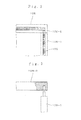
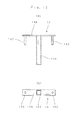
- Figs. 1 to 16 show a preferred embodiment of a panel structure of first panels.
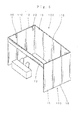
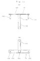
- a booth 100 that is a connected structure of the first panels has both right and left sides and a rear side, which are configured with walls 110, and a front side that is open, and the wall 110 is constituted with a plurality of first partition panels 10 and first support pillars 12.
- the first partition panel 10 may have various dimensions such as 2700 mm in height ⁇ 1000 mm in width, 2500 mm in height ⁇ 1000 mm in width, 2400 mm in height ⁇ 1000 mm in width, 2100 mm in height ⁇ 900 mm in width, and 1800 mm in height ⁇ 900 mm in width.
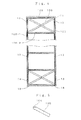
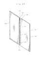
- the first partition panel 10 is configured so that a rectangular frame 10B is interposed detachably attached between thin side panels 10C, and decoration is applied to the surface of the thin side panel 10C by painting the surface and then attaching a fabric or decoration sheet thereto.
- the rectangular frame 10B has vertical bars 10B-1 and horizontal bars 10B-2 arranged with a vertical gap between the right and left vertical bars 10B-1 so that the rectangular frame 10B is detachable from the structure as shown in Fig. 3 .
- Tacker needles may be driven and fixed into the horizontal bar 10B-2 to be fixed to the vertical bar 10B-1 of the partition panel 10.
- a braced reinforcing bar 10G having a front end 10H processed perpendicularly may be fixed to the vertical bar 10B-1 and the horizontal bar 10B-2 by means of Tacker needles or the like to increase the strength of the partition panel 10.
- attachment holes 10B-3 are perforated at both ends of the vertical bar 10B-1 so that an attaching metal component 10B-4 having a screw hole is inserted therein, while an insert hole 10B-6 is perforated in the upper and lower horizontal bars 10B-2 so that an attachment screw 10B-5 is inserted through the insert hole and is screwed with the corresponding attaching metal component 10B-4, thereby constituting the rectangular frame 10B.
- attachment holes 10B-3 are perforated at both ends of the horizontal bar 10B-2 so that an attachment tool 10B-4 having a screw hole is inserted thereon, while an insert hole 10B-6 is perforated in the vertical bar 10B-1 so that the attachment screw 10B-5 is inserted through the insert hole 10B-6 and screwed to the attaching metal component 10B-4, thereby attaching the intermediate horizontal bar 10B-2.
- the partition panel 10 is dissembled into the rectangular frame 10B and the side panels 10C, and then the side panels 10C are piled up and the rectangular frame 10B is dissembled into the vertical bars 10B-1 and the horizontal bars 10B-2.
- the partition panel 10 may be received in, for example, a corrugated box and then carried easily.
- one of Hook-and-Loop fasteners 10D which is manufactured to have a width with so coupling force as the side panel 10C is not broken when being separated, is fixed to the panel attachment surface of the vertical bar 10B-1 and the horizontal bar 10B-2 of the rectangular frame 10B with a shape corresponding to the appearance of the side panel 10C by means of an adhesive or double-sided adhesive tape
- the other of Hook-and-Loop fasteners 10E is fixed to the rear surface of the side panel 10C with a continuous shape corresponding to the outer shape of the side panel 10C by means of an adhesive or double-sided adhesive tape so that the side panel 10C is detachably attached to the rectangular frame 10B.
- the rectangular frame 10B and the side panel 10C are installed so that the right and left vertical bars 10B-1 are at locations deviated in an inner direction from the side periphery of the side panel 10C and the upper horizontal bars 10B-2 are at locations deviated in a lower direction from the upper periphery of the side panel 10C.
- grooves are formed in both right and left sides and the upper periphery of the first partition panel 10 over the entire length thereof.
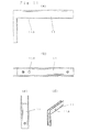
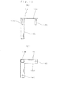
- Reinforcing metal components 11, 18 are fixed to four upper and lower edges of the first partition panel 10 by screws or the like, and a reinforcing metal component 19 having a grooved section is inserted into the upper groove 10A of the first partition panel 10 and fixed thereto by screws or the like.
- the reinforcing metal component 11 at the upper edge portion of the first partition panel 10 also has a grooved section with a L-shaped side, a pin inserting hole 11A is formed in a bottom of the upper side of the groove 10A. Also, the reinforcing metal component 18 at the other side has an L-shaped side, and the vertical side is formed at the grooved section.
- a plurality of, for example 5 sheets of magnet boards 13 are fixed with vertical intervals to the bottom of the grooves 10A at both sides of the first partition panel 10.
- a metal pipe having a rectangular section with a size inserted into the groove 10A in the edge of two partition panels 10 successively arranged is used for the first support pillar 12 so that the first support 12 has an open upper end.
- first partition panel 10 is connected to the first support pillar 12 by means of a connecting metal component 14.
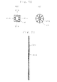
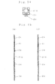
- the connecting metal component 14 fixes a connecting pillar portion 14B to a center of a connecting plate portion 14A and fixes an inserting pin 14C to a side thereof so as to form a planar linear shape ( Fig. 12 ), a planar L shape ( Fig. 13 ), a planar T shape ( Fig. 14 ) or a planar cross-shaped shape ( Fig. 15 ) in the connecting plate 14A.
- an insert hole 11B is elongated downward in the reinforcing metal component 11 and the edge portion of the upper groove 10A of the first partition panel 10 so that a power cord line 20B may pass through the partition panel 10.
- the vertical bars 10B-1 and the horizontal bars 10B-2 are laid out into a rectangular pattern so that the vertical bars 10B-1 and the horizontal bars 10B-2 are connected by means of the insertion combination as shown in Fig. 3 to assemble the rectangular frame 10B, and the vertical bars 10B-1 are fixed to the horizontal bars 10B-2 by driving Tacker needles.
- one of Hook-and-Loop fasteners 10D with a predetermined width is fixed to the vertical bars 10B-1 and the horizontal bars 10B-2 of the rectangular frame 10B by means of an adhesive or double-sided adhesive tape with a continuous shape corresponding to the outer shape of the side panel 10C.
- the other of Hook-and-Loop fasteners 10E with a continuous shape according to the outer shape of the side panel 10C is fixed to the rear surface of the side panel 10C by means of an adhesive or double-sided adhesive tape, so that the side panel 10C may be detachably attached to the rectangular frame 10B by engaging Hook-and-Loop fasteners 10D, 10E with each other.
- dimensions are set so that the side end periphery of the rectangular frame 10B is at a location deviated inwards from the side end periphery of the side panel 10C and the upper end periphery is at a location deviated downwards from the upper periphery, and then the grooves 10A are formed in both sides and the upper portion of the partition panel 10.
- a side panel 10C having a decoration or design acceptable to the taste of a user or the circumstance of an exhibition hall may be prepared and replaced with the existing one.
- a booth 100 In a case that a booth 100 is assembled, three or four partition panels 10 are arranged, and then the support pillar 12 is inserted into the groove 10A at the side periphery of adjacent partition panels 10. Then, the magnet board 13 of the partition panel 10 is strongly magnetically attached to the support pillar 12 so that three or four partition panels 10 are temporarily connected. At this time, if the magnet board 13 has a strong magnetic force, a vertical position of the partition panel 10 may be adjusted with respect to the support 12. Thus, the support pillar 12 and the partition panel 10 may securely stand in a stable way even on an uneven floor (or, ground).
- the connecting metal component 14 having a straight connecting plate portion 14A
- the connecting metal component 14 is inserted into the groove 10A of the partition panel 10 through adjacent partition panels 10.
- the connecting pillar portion 14B is inserted into the upper end opening 12A of the support pillar 12 and the inserting pin 14C is inserted into the pin insertion hole 11A, the adjacent partition panels 10 may be securely connected.
- the partition panels 10 When the partition panels 10 may be connected as above, the partition panels 10 are made stand up to be perpendicular. Then, the support pillar 12 is inserted into the groove 10A at an outer end thereof, the partition panel 10 may be magnetically attached and thus temporarily connected to the support pillar 12 in an orthogonal state by means of the magnet board 13. Thus, finally, if the L-shaped connecting plate portion 14A is connected to the partition panel 10 at the outer end by using the connecting metal component 14, three or four partition panels stand up. Then, as shown in Fig. 6 , if the walls 110 of both right and left sides and the rear sides and rear surfaces are formed to connect the front surface with the connecting plate 17, the booth 100 may be assembled.
- a clip 20A clamps the sidewall of the groove 10A of the partition panel 10, for example fixes the lighting device 20, as necessary, so that the power cord line 20B is arranged with well look in the groove 10A passes through the partition panel 10 from the insert hole 11B.
- the above processes may be performed in a reverse order.
- the support pillar 12 may be connected in a simple way by means of the partition panels 10 and also may be simply dissembled. Further, the partition panel 10 may strongly connect the support 12 not only by using a magnet but also by using the connecting metal component 14 having the connecting plate portion 14A, the inserting pin portion 14C and the connecting pillar portion 14B, and thus the partition panel 10 does not fall down even if a great impact is applied to the partition panel 10 for some reason.
- the booths 100 with a complicated structure may be assembled by using a connecting metal component 14 with a planar T-shaped connecting plate portion 14A and a connecting metal component 14 with a planar T-shaped connecting plate portion 14A.
- partition panel 10 has a flat lower portion in the above example, a groove may be formed in the lower portion thereof to have the same structure as the upper portion.
- a wall may be formed in the front surface so that an entrance is formed in the wall.
- FIGs. 17 to 23 show an example of the panel connecting structure in a case that booths having different structures are established.
- a booth 100 having the first panel structure is configured by connecting the first support pillar 12 with the first partition panel 10
- a booth 200 having the second panel structure is configured by connecting a second support pillar 21 with the second partition panel 20.
- the booth of the second structure may adopt a known one, for example Octonorm SystemTM.
- the first partition panel 10 has three peripheries with a groove shape as described above, and the magnet boards 13 are fixed with vertical intervals to the bottom of the side groove 10A of the first partition panel 10 so that the first support pillar 12 is formed at the appearance inserted into the side groove 10A of the first partition panel 10, and thus the first support pillar 12 is magnetically fixed to the bottom of the side groove 10A of the first partition panel 10 by means of the magnet board 13.
- the second partition panel 20 has the connecting component 22 fixed to an upper end of the side and a lower end thereof, and the connecting component 22 fixes bases of three small band pieces 22A, 22B, 22C as shown in Fig. 19 so that a front end of the screw is connected to the small band piece 22B at the center so that the small band pieces 22A, 22C at both sides are connected at the middle of the screw.
- the front ends of the small band pieces 22A, 22C at both sides and the small band piece 22B at the center are expanded from each other by rotating the hexagonal hole 22D or the screw 22E, and the front ends of the small band pieces 22A, 22C at both sides and the small band piece 22B at the center are closed by means of reverse rotation.
- the second support pillar 21 has a rectangular section, and dovetail grooves 21A are formed at four sides over the entire length.
- the second partition panel 20 is connected to the second support pillar 21 when the front end of the connecting component 22 of the second partition panel 20 is inserted, enlarged and drawn out.
- the second support pillar 21 may have an octagonal section as shown in Fig. 20b , and a dovetail groove 21A may be formed in each side thereof.
- a receiving space 10H is perforated in the side of the first partition panel 10 so that the connecting component 22 of the second partition panel 20 is received therein frequently without restriction.
- the first partition panel 10 may be connected to the second support pillar 21 by inserting, enlarging and drawing out the connecting component 22 of the first partition panel 10 to the dovetail groove 21A of the second support pillar 21.
- the first partition panel 10 and the second partition panel 20, which have different connecting methods, may be connected to one panel by means of the second support pillar 21.
- Figs. 24 to 26 show a second embodiment of the panel connecting structure.
- a plurality of magnetically attachable connecting blocks (a fourth connecting component) 24 are fixed to the side of the second support pillar 21 by means of screws with gaps corresponding to the magnet board 13 at the bottom of the side groove 10A of the first partition panel 10.
- the second support pillar 21 when the second support pillar 21 is inserted into the side groove 10A of the first partition panel 10, the second support pillar 21 is magnetically attached to the magnet board 13 at the bottom of the groove 10A.
- the first partition panel 10 is strongly connected to the second support pillar 21, and thus they may be connected like one panel as in the first embodiment.
Landscapes
- Engineering & Computer Science (AREA)
- Architecture (AREA)
- Civil Engineering (AREA)
- Structural Engineering (AREA)
- Physics & Mathematics (AREA)
- Electromagnetism (AREA)
- Panels For Use In Building Construction (AREA)
- Finishing Walls (AREA)
- Joining Of Building Structures In Genera (AREA)
Applications Claiming Priority (1)
| Application Number | Priority Date | Filing Date | Title |
|---|---|---|---|
| JP2010290013A JP5735270B2 (ja) | 2010-12-27 | 2010-12-27 | 間仕切りパネル及びパネルの連結構造 |
Publications (1)
| Publication Number | Publication Date |
|---|---|
| EP2468972A2 true EP2468972A2 (de) | 2012-06-27 |
Family
ID=44318208
Family Applications (1)
| Application Number | Title | Priority Date | Filing Date |
|---|---|---|---|
| EP11168404A Withdrawn EP2468972A2 (de) | 2010-12-27 | 2011-06-01 | Trennwand mit einer Vorder- und Rückwand, die an einem Rahmen mittels Klettverschlüssen befestigt ist |
Country Status (5)
| Country | Link |
|---|---|
| US (1) | US20120216484A1 (de) |
| EP (1) | EP2468972A2 (de) |
| JP (1) | JP5735270B2 (de) |
| CN (1) | CN202176032U (de) |
| CA (1) | CA2734049A1 (de) |
Families Citing this family (14)
| Publication number | Priority date | Publication date | Assignee | Title |
|---|---|---|---|---|
| JP2014097291A (ja) * | 2012-10-15 | 2014-05-29 | Cool Kobe Co Ltd | 足冷え防止用具 |
| CN102871353A (zh) * | 2012-11-07 | 2013-01-16 | 迈柯唯医疗设备(苏州)有限公司 | 拆分式储物分层隔板结构 |
| DE202014100622U1 (de) * | 2014-02-12 | 2015-05-15 | Michael Linden | Präsentationsmöbel für Waren |
| JP6358866B2 (ja) * | 2014-06-16 | 2018-07-18 | パラマウントベッド株式会社 | ベッド用ボードの主構造体 |
| JP6181026B2 (ja) * | 2014-10-22 | 2017-08-16 | ジャパンレントオール株式会社 | 表示パネル |
| JP6431354B2 (ja) * | 2014-12-10 | 2018-11-28 | ジャパンレントオール株式会社 | パネルの連結構造 |
| KR101665101B1 (ko) * | 2016-04-06 | 2016-10-24 | 주식회사 코아스 | 패널 |
| KR101722559B1 (ko) * | 2016-04-06 | 2017-04-03 | 주식회사 코아스 | 패널의 설치장치 |
| JP6717449B2 (ja) * | 2016-06-15 | 2020-07-01 | 関東商会株式会社 | 組立式パーティション |
| CN113167068B (zh) * | 2018-11-09 | 2024-01-30 | 宜家供应有限公司 | 用于将房间分隔件系统的两个面板附接的附接构件以及包括所述附接构件的房间分隔件系统 |
| WO2020096521A1 (en) * | 2018-11-09 | 2020-05-14 | Ikea Supply Ag | Attachment member for attaching two panels of a room divider system and a room divider system comprising said attachment member |
| SE1851615A1 (en) | 2018-11-09 | 2020-05-10 | Ikea Supply Ag | Room divider system |
| CN109736485A (zh) * | 2018-11-23 | 2019-05-10 | 安徽耐特嘉信息科技有限公司 | 一种新型轻质内隔墙体 |
| JP2023159519A (ja) * | 2022-04-20 | 2023-11-01 | ジャパンレントオール株式会社 | 間仕切りパネル |
Citations (2)
| Publication number | Priority date | Publication date | Assignee | Title |
|---|---|---|---|---|
| JPH03151022A (ja) | 1989-11-08 | 1991-06-27 | Mitsui Toatsu Chem Inc | 排ガス処理装置 |
| JP2001090232A (ja) | 1999-09-28 | 2001-04-03 | Design Art Studio:Kk | 仮設用間仕切りパネル |
Family Cites Families (4)
| Publication number | Priority date | Publication date | Assignee | Title |
|---|---|---|---|---|
| JPH0366312U (de) * | 1989-10-30 | 1991-06-27 | ||
| JP3027256U (ja) * | 1996-01-26 | 1996-08-09 | 東丸木材工業有限会社 | パネル構造材 |
| JP3511257B2 (ja) * | 1999-01-25 | 2004-03-29 | 株式会社岡村製作所 | 間仕切パネル取付構造 |
| JP3151022U (ja) * | 2009-03-25 | 2009-06-04 | ジャパンレントオール株式会社 | ブース構造 |
-
2010
- 2010-12-27 JP JP2010290013A patent/JP5735270B2/ja active Active
-
2011
- 2011-03-15 CA CA2734049A patent/CA2734049A1/en not_active Abandoned
- 2011-06-01 EP EP11168404A patent/EP2468972A2/de not_active Withdrawn
- 2011-06-14 CN CN2011202004441U patent/CN202176032U/zh not_active Expired - Lifetime
- 2011-12-27 US US13/337,476 patent/US20120216484A1/en not_active Abandoned
Patent Citations (2)
| Publication number | Priority date | Publication date | Assignee | Title |
|---|---|---|---|---|
| JPH03151022A (ja) | 1989-11-08 | 1991-06-27 | Mitsui Toatsu Chem Inc | 排ガス処理装置 |
| JP2001090232A (ja) | 1999-09-28 | 2001-04-03 | Design Art Studio:Kk | 仮設用間仕切りパネル |
Also Published As
| Publication number | Publication date |
|---|---|
| CN202176032U (zh) | 2012-03-28 |
| JP5735270B2 (ja) | 2015-06-17 |
| US20120216484A1 (en) | 2012-08-30 |
| JP2012136870A (ja) | 2012-07-19 |
| CA2734049A1 (en) | 2012-06-27 |
Similar Documents
| Publication | Publication Date | Title |
|---|---|---|
| EP2468972A2 (de) | Trennwand mit einer Vorder- und Rückwand, die an einem Rahmen mittels Klettverschlüssen befestigt ist | |
| US7306107B2 (en) | Organizer wall | |
| US20140034596A1 (en) | Modular exhibit structure | |
| JPH11159033A (ja) | 展示パネルの連結部材及び展示用パラペット | |
| JP3151022U (ja) | ブース構造 | |
| WO2018197303A1 (en) | Wall element, mounting element kit and hanging element profile | |
| US7971404B2 (en) | Systems and methods for installing panels | |
| KR101537086B1 (ko) | 조립과 분해가 용이한 친환경 부스 | |
| US5237791A (en) | Modular structures and components thereof | |
| KR101823911B1 (ko) | 경량구조물의 패널 연결장치 | |
| KR102107655B1 (ko) | 페그보드 설치장치 | |
| JP2023159519A (ja) | 間仕切りパネル | |
| JP3226253U (ja) | 間仕切りパネル | |
| KR100934036B1 (ko) | 조립식 상품진열대 구조 | |
| GB2507583A (en) | Partition wall panel with hook connection system | |
| KR101537087B1 (ko) | 조립과 분해가 용이한 친환경 부스 | |
| JP2005102739A (ja) | デスク用パネル装置 | |
| US20170284079A1 (en) | Self-interlocking blocks for habitable structures | |
| JP2005102737A (ja) | 自在な展開を可能にしたデスク | |
| KR102922436B1 (ko) | 전시용 가벽 | |
| JP5572410B2 (ja) | 自立型間仕切り | |
| JP2005102742A (ja) | デスクパネル | |
| KR102657854B1 (ko) | 전시 부스용 목재 조립식 패널 | |
| CA2671579C (en) | Modular exhibit structure | |
| KR200210940Y1 (ko) | 구조물 조립 구조 |
Legal Events
| Date | Code | Title | Description |
|---|---|---|---|
| AK | Designated contracting states |
Kind code of ref document: A2 Designated state(s): AL AT BE BG CH CY CZ DE DK EE ES FI FR GB GR HR HU IE IS IT LI LT LU LV MC MK MT NL NO PL PT RO RS SE SI SK SM TR |
|
| AX | Request for extension of the european patent |
Extension state: BA ME |
|
| PUAI | Public reference made under article 153(3) epc to a published international application that has entered the european phase |
Free format text: ORIGINAL CODE: 0009012 |
|
| STAA | Information on the status of an ep patent application or granted ep patent |
Free format text: STATUS: THE APPLICATION IS DEEMED TO BE WITHDRAWN |
|
| 18D | Application deemed to be withdrawn |
Effective date: 20140103 |