EP2467760B1 - Tastenlose eingabevorrichtung mit kapazitätssensor zur objekterkennung - Google Patents
Tastenlose eingabevorrichtung mit kapazitätssensor zur objekterkennung Download PDFInfo
- Publication number
- EP2467760B1 EP2467760B1 EP10810469.6A EP10810469A EP2467760B1 EP 2467760 B1 EP2467760 B1 EP 2467760B1 EP 10810469 A EP10810469 A EP 10810469A EP 2467760 B1 EP2467760 B1 EP 2467760B1
- Authority
- EP
- European Patent Office
- Prior art keywords
- sensor
- conductor
- vehicle
- vehicle opening
- assembly
- Prior art date
- Legal status (The legal status is an assumption and is not a legal conclusion. Google has not performed a legal analysis and makes no representation as to the accuracy of the status listed.)
- Not-in-force
Links
- 239000004020 conductor Substances 0.000 claims description 74
- 229910052751 metal Inorganic materials 0.000 claims description 13
- 239000002184 metal Substances 0.000 claims description 13
- 238000010276 construction Methods 0.000 claims description 8
- 125000006850 spacer group Chemical group 0.000 claims description 8
- 230000008878 coupling Effects 0.000 claims description 6
- 238000010168 coupling process Methods 0.000 claims description 6
- 238000005859 coupling reaction Methods 0.000 claims description 6
- 230000004044 response Effects 0.000 claims description 6
- 210000003195 fascia Anatomy 0.000 description 57
- 230000004913 activation Effects 0.000 description 23
- 238000001514 detection method Methods 0.000 description 17
- 230000006870 function Effects 0.000 description 17
- RKLLTEAEZIJBAU-UHFFFAOYSA-N 1,2-dichloro-4-(2,4-dichlorophenyl)benzene Chemical compound ClC1=CC(Cl)=CC=C1C1=CC=C(Cl)C(Cl)=C1 RKLLTEAEZIJBAU-UHFFFAOYSA-N 0.000 description 13
- 239000000463 material Substances 0.000 description 13
- 238000000576 coating method Methods 0.000 description 9
- 239000004033 plastic Substances 0.000 description 9
- 229920003023 plastic Polymers 0.000 description 9
- RYGMFSIKBFXOCR-UHFFFAOYSA-N Copper Chemical compound [Cu] RYGMFSIKBFXOCR-UHFFFAOYSA-N 0.000 description 6
- 229910052802 copper Inorganic materials 0.000 description 6
- 239000010949 copper Substances 0.000 description 6
- 230000004888 barrier function Effects 0.000 description 5
- 239000011248 coating agent Substances 0.000 description 5
- 229920001971 elastomer Polymers 0.000 description 5
- 230000033001 locomotion Effects 0.000 description 5
- 238000004891 communication Methods 0.000 description 4
- 230000003750 conditioning effect Effects 0.000 description 4
- 239000000806 elastomer Substances 0.000 description 4
- 239000012811 non-conductive material Substances 0.000 description 4
- 239000000853 adhesive Substances 0.000 description 3
- 230000001070 adhesive effect Effects 0.000 description 3
- 229910052782 aluminium Inorganic materials 0.000 description 3
- XAGFODPZIPBFFR-UHFFFAOYSA-N aluminium Chemical compound [Al] XAGFODPZIPBFFR-UHFFFAOYSA-N 0.000 description 3
- 230000000712 assembly Effects 0.000 description 3
- 238000000429 assembly Methods 0.000 description 3
- 239000003990 capacitor Substances 0.000 description 3
- 239000006260 foam Substances 0.000 description 3
- 239000000976 ink Substances 0.000 description 3
- OKTJSMMVPCPJKN-UHFFFAOYSA-N Carbon Chemical compound [C] OKTJSMMVPCPJKN-UHFFFAOYSA-N 0.000 description 2
- 238000013459 approach Methods 0.000 description 2
- 238000013475 authorization Methods 0.000 description 2
- 229910052799 carbon Inorganic materials 0.000 description 2
- 230000008859 change Effects 0.000 description 2
- 239000004744 fabric Substances 0.000 description 2
- 238000005286 illumination Methods 0.000 description 2
- 150000002739 metals Chemical class 0.000 description 2
- 238000000034 method Methods 0.000 description 2
- 230000003287 optical effect Effects 0.000 description 2
- 230000035945 sensitivity Effects 0.000 description 2
- 229910001369 Brass Inorganic materials 0.000 description 1
- 229910000906 Bronze Inorganic materials 0.000 description 1
- 239000004593 Epoxy Substances 0.000 description 1
- 229920004142 LEXAN™ Polymers 0.000 description 1
- NIXOWILDQLNWCW-UHFFFAOYSA-N acrylic acid group Chemical group C(C=C)(=O)O NIXOWILDQLNWCW-UHFFFAOYSA-N 0.000 description 1
- 230000009471 action Effects 0.000 description 1
- 238000004873 anchoring Methods 0.000 description 1
- 238000003491 array Methods 0.000 description 1
- 230000008901 benefit Effects 0.000 description 1
- 230000005540 biological transmission Effects 0.000 description 1
- 239000010951 brass Substances 0.000 description 1
- 239000010974 bronze Substances 0.000 description 1
- 239000000969 carrier Substances 0.000 description 1
- 238000012790 confirmation Methods 0.000 description 1
- 239000000356 contaminant Substances 0.000 description 1
- KUNSUQLRTQLHQQ-UHFFFAOYSA-N copper tin Chemical compound [Cu].[Sn] KUNSUQLRTQLHQQ-UHFFFAOYSA-N 0.000 description 1
- 238000013461 design Methods 0.000 description 1
- 230000007613 environmental effect Effects 0.000 description 1
- 125000003700 epoxy group Chemical group 0.000 description 1
- 230000001747 exhibiting effect Effects 0.000 description 1
- 239000011152 fibreglass Substances 0.000 description 1
- 229920001821 foam rubber Polymers 0.000 description 1
- 239000011888 foil Substances 0.000 description 1
- AMGQUBHHOARCQH-UHFFFAOYSA-N indium;oxotin Chemical compound [In].[Sn]=O AMGQUBHHOARCQH-UHFFFAOYSA-N 0.000 description 1
- 238000009434 installation Methods 0.000 description 1
- 230000007246 mechanism Effects 0.000 description 1
- 238000004806 packaging method and process Methods 0.000 description 1
- 239000003973 paint Substances 0.000 description 1
- 229920000515 polycarbonate Polymers 0.000 description 1
- 239000004417 polycarbonate Substances 0.000 description 1
- 229920000647 polyepoxide Polymers 0.000 description 1
- 229920006267 polyester film Polymers 0.000 description 1
- 230000008569 process Effects 0.000 description 1
- 230000001681 protective effect Effects 0.000 description 1
- 239000011347 resin Substances 0.000 description 1
- 229920005989 resin Polymers 0.000 description 1
- 239000007787 solid Substances 0.000 description 1
- 238000002834 transmittance Methods 0.000 description 1
Images


Classifications
-
- E—FIXED CONSTRUCTIONS
- E05—LOCKS; KEYS; WINDOW OR DOOR FITTINGS; SAFES
- E05F—DEVICES FOR MOVING WINGS INTO OPEN OR CLOSED POSITION; CHECKS FOR WINGS; WING FITTINGS NOT OTHERWISE PROVIDED FOR, CONCERNED WITH THE FUNCTIONING OF THE WING
- E05F15/00—Power-operated mechanisms for wings
- E05F15/40—Safety devices, e.g. detection of obstructions or end positions
- E05F15/42—Detection using safety edges
- E05F15/46—Detection using safety edges responsive to changes in electrical capacitance
-
- B—PERFORMING OPERATIONS; TRANSPORTING
- B60—VEHICLES IN GENERAL
- B60R—VEHICLES, VEHICLE FITTINGS, OR VEHICLE PARTS, NOT OTHERWISE PROVIDED FOR
- B60R25/00—Fittings or systems for preventing or indicating unauthorised use or theft of vehicles
- B60R25/20—Means to switch the anti-theft system on or off
- B60R25/2045—Means to switch the anti-theft system on or off by hand gestures
-
- E—FIXED CONSTRUCTIONS
- E05—LOCKS; KEYS; WINDOW OR DOOR FITTINGS; SAFES
- E05F—DEVICES FOR MOVING WINGS INTO OPEN OR CLOSED POSITION; CHECKS FOR WINGS; WING FITTINGS NOT OTHERWISE PROVIDED FOR, CONCERNED WITH THE FUNCTIONING OF THE WING
- E05F15/00—Power-operated mechanisms for wings
- E05F15/70—Power-operated mechanisms for wings with automatic actuation
- E05F15/73—Power-operated mechanisms for wings with automatic actuation responsive to movement or presence of persons or objects
-
- E—FIXED CONSTRUCTIONS
- E05—LOCKS; KEYS; WINDOW OR DOOR FITTINGS; SAFES
- E05F—DEVICES FOR MOVING WINGS INTO OPEN OR CLOSED POSITION; CHECKS FOR WINGS; WING FITTINGS NOT OTHERWISE PROVIDED FOR, CONCERNED WITH THE FUNCTIONING OF THE WING
- E05F15/00—Power-operated mechanisms for wings
-
- E—FIXED CONSTRUCTIONS
- E05—LOCKS; KEYS; WINDOW OR DOOR FITTINGS; SAFES
- E05F—DEVICES FOR MOVING WINGS INTO OPEN OR CLOSED POSITION; CHECKS FOR WINGS; WING FITTINGS NOT OTHERWISE PROVIDED FOR, CONCERNED WITH THE FUNCTIONING OF THE WING
- E05F15/00—Power-operated mechanisms for wings
- E05F15/60—Power-operated mechanisms for wings using electrical actuators
- E05F15/603—Power-operated mechanisms for wings using electrical actuators using rotary electromotors
- E05F15/611—Power-operated mechanisms for wings using electrical actuators using rotary electromotors for swinging wings
- E05F15/616—Power-operated mechanisms for wings using electrical actuators using rotary electromotors for swinging wings operated by push-pull mechanisms
-
- E—FIXED CONSTRUCTIONS
- E05—LOCKS; KEYS; WINDOW OR DOOR FITTINGS; SAFES
- E05Y—INDEXING SCHEME ASSOCIATED WITH SUBCLASSES E05D AND E05F, RELATING TO CONSTRUCTION ELEMENTS, ELECTRIC CONTROL, POWER SUPPLY, POWER SIGNAL OR TRANSMISSION, USER INTERFACES, MOUNTING OR COUPLING, DETAILS, ACCESSORIES, AUXILIARY OPERATIONS NOT OTHERWISE PROVIDED FOR, APPLICATION THEREOF
- E05Y2400/00—Electronic control; Electrical power; Power supply; Power or signal transmission; User interfaces
- E05Y2400/80—User interfaces
- E05Y2400/85—User input means
- E05Y2400/852—Sensors
-
- E—FIXED CONSTRUCTIONS
- E05—LOCKS; KEYS; WINDOW OR DOOR FITTINGS; SAFES
- E05Y—INDEXING SCHEME ASSOCIATED WITH SUBCLASSES E05D AND E05F, RELATING TO CONSTRUCTION ELEMENTS, ELECTRIC CONTROL, POWER SUPPLY, POWER SIGNAL OR TRANSMISSION, USER INTERFACES, MOUNTING OR COUPLING, DETAILS, ACCESSORIES, AUXILIARY OPERATIONS NOT OTHERWISE PROVIDED FOR, APPLICATION THEREOF
- E05Y2400/00—Electronic control; Electrical power; Power supply; Power or signal transmission; User interfaces
- E05Y2400/80—User interfaces
- E05Y2400/85—User input means
- E05Y2400/856—Actuation thereof
- E05Y2400/858—Actuation thereof by body parts, e.g. by feet
- E05Y2400/86—Actuation thereof by body parts, e.g. by feet by hand
-
- E—FIXED CONSTRUCTIONS
- E05—LOCKS; KEYS; WINDOW OR DOOR FITTINGS; SAFES
- E05Y—INDEXING SCHEME ASSOCIATED WITH SUBCLASSES E05D AND E05F, RELATING TO CONSTRUCTION ELEMENTS, ELECTRIC CONTROL, POWER SUPPLY, POWER SIGNAL OR TRANSMISSION, USER INTERFACES, MOUNTING OR COUPLING, DETAILS, ACCESSORIES, AUXILIARY OPERATIONS NOT OTHERWISE PROVIDED FOR, APPLICATION THEREOF
- E05Y2600/00—Mounting or coupling arrangements for elements provided for in this subclass
- E05Y2600/40—Mounting location; Visibility of the elements
- E05Y2600/46—Mounting location; Visibility of the elements in or on the wing
-
- E—FIXED CONSTRUCTIONS
- E05—LOCKS; KEYS; WINDOW OR DOOR FITTINGS; SAFES
- E05Y—INDEXING SCHEME ASSOCIATED WITH SUBCLASSES E05D AND E05F, RELATING TO CONSTRUCTION ELEMENTS, ELECTRIC CONTROL, POWER SUPPLY, POWER SIGNAL OR TRANSMISSION, USER INTERFACES, MOUNTING OR COUPLING, DETAILS, ACCESSORIES, AUXILIARY OPERATIONS NOT OTHERWISE PROVIDED FOR, APPLICATION THEREOF
- E05Y2900/00—Application of doors, windows, wings or fittings thereof
- E05Y2900/50—Application of doors, windows, wings or fittings thereof for vehicles
- E05Y2900/53—Type of wing
- E05Y2900/531—Doors
-
- E—FIXED CONSTRUCTIONS
- E05—LOCKS; KEYS; WINDOW OR DOOR FITTINGS; SAFES
- E05Y—INDEXING SCHEME ASSOCIATED WITH SUBCLASSES E05D AND E05F, RELATING TO CONSTRUCTION ELEMENTS, ELECTRIC CONTROL, POWER SUPPLY, POWER SIGNAL OR TRANSMISSION, USER INTERFACES, MOUNTING OR COUPLING, DETAILS, ACCESSORIES, AUXILIARY OPERATIONS NOT OTHERWISE PROVIDED FOR, APPLICATION THEREOF
- E05Y2900/00—Application of doors, windows, wings or fittings thereof
- E05Y2900/50—Application of doors, windows, wings or fittings thereof for vehicles
- E05Y2900/53—Type of wing
- E05Y2900/546—Tailboards, tailgates or sideboards opening upwards
-
- E—FIXED CONSTRUCTIONS
- E05—LOCKS; KEYS; WINDOW OR DOOR FITTINGS; SAFES
- E05Y—INDEXING SCHEME ASSOCIATED WITH SUBCLASSES E05D AND E05F, RELATING TO CONSTRUCTION ELEMENTS, ELECTRIC CONTROL, POWER SUPPLY, POWER SIGNAL OR TRANSMISSION, USER INTERFACES, MOUNTING OR COUPLING, DETAILS, ACCESSORIES, AUXILIARY OPERATIONS NOT OTHERWISE PROVIDED FOR, APPLICATION THEREOF
- E05Y2900/00—Application of doors, windows, wings or fittings thereof
- E05Y2900/50—Application of doors, windows, wings or fittings thereof for vehicles
- E05Y2900/53—Type of wing
- E05Y2900/548—Trunk lids
Definitions
- the present invention relates to keyless entry assemblies for vehicles.
- An object of the present invention is a keyless entry assembly having a capacitance sensor and a controller in which the sensor detects an object in proximity with or touching a vehicle opening such as a door, trunk, hatch, or the like and the controller controls the vehicle opening based on detection of the object.
- Another object of the present invention is a keyless entry assembly having a capacitance sensor and a controller in which the sensor detects an object in proximity with or touching a vehicle opening, the sensor is in the form of an emblem or the like indicative of a vehicle, and the controller controls the vehicle opening based on detection of the object.
- a further object of the present invention is a keyless entry assembly having a capacitance sensor and a controller in which the sensor detects a user in proximity with or touching a vehicle opening and the controller controls the vehicle opening based on detection of the user and detection of an authorized key fob in possession by the user.
- the present invention provides a keyless entry assembly having a vehicle opening movable between a locked position and an unlocked position, an electrical conductor (i.e., a capacitance sensor) mounted to an exterior surface of the vehicle opening, and a controller.
- the conductor capacitively couples to an electrically conductive object proximal to the conductor while the conductor is driven with an electrical charge such that capacitance of the conductor changes due to the conductor capacitively coupling with the object.
- the conductor is in the shape of an emblem identifying a vehicle to be associated with the vehicle opening.
- the controller is operable for driving the conductor with the electrical charge and measuring the capacitance of the conductor to determine whether an electrically conductive object is proximal to the conductor.
- the controller is further operable for controlling the vehicle opening to move the vehicle opening from one of the positions to the other of the positions upon determining that an electrically conductive object is proximal to the conductor.
- the present invention provides a keyless entry assembly having an electrical conductor (i.e., a capacitance sensor) and a controller.
- the conductor is mountable to an exterior surface of a vehicle opening movable between a locked position and an unlocked position.
- the conductor capacitively couples to an electrically conductive object proximal to the conductor while the conductor is driven with an electrical charge such that capacitance of the conductor changes due to the conductor capacitively coupling with the object.
- the conductor is in the shape of an emblem identifying a vehicle to be associated with the vehicle opening.
- the controller is operable for driving the conductor with the electrical charge and measuring the capacitance of the conductor to determine whether an electrically conductive object is proximal to the conductor.
- the controller is further operable for controlling the vehicle opening to move the vehicle opening from one of the positions to the other of the positions upon determining that an electrically conductive object is proximal to the conductor.
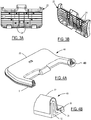
- a vehicle lift gate assembly 10 having a lift gate 12 is shown.
- Lift gate 12 is connected by a cylinder 14 or the like to a body panel 16 of a vehicle.
- Cylinder 14 includes a piston rod which extends to move lift gate 12 to an opened position with respect to body panel 16 and contracts to move lift gate 12 to a closed position with respect to body panel 16 (lift gate 12 in the closed position is shown as a dotted line in FIG. 1A ).
- a capacitance sensor 18 is mounted along body panel 16. Sensor 18 is operable for detecting the presence of an electrically conductive object such as a human body part extending into the opening between lift gate 12 and body panel 16 when the object is proximal to body panel 16.
- Sensor 18 is part of an anti-entrapment system which includes a controller.
- Sensor 18 generally includes separated first and second electrically conductive conductors with a dielectric element therebetween. The conductors are set at different voltage potentials with respect to one another with one of the conductors typically being set at electrical ground.
- Sensor 18 has an associated capacitance which is a function of the different voltage potentials applied to the conductors. The capacitance of sensor 18 changes in response to the conductors being physically moved relative to one another such as when an object (either electrically conductive or non-conductive) touches sensor 18. Similarly, the capacitance of sensor 18 changes when an electrically conductive object comes into proximity with the conductor of sensor 18 that is not electrically grounded. As such, sensor 18 is operable to detect an object on sensor 18 (i.e., an object touching sensor 18) and/or the presence of an object near sensor 18 (i.e., an object in proximity to sensor 18).
- the controller is in communication with sensor 18 to monitor the capacitance of sensor 18.
- the controller controls lift gate 12 accordingly via cylinder 14.
- the controller controls lift gate 12 to halt movement in the closing direction when sensor 18 detects the presence of an object near sensor 18.
- the object may be a human such as a child and the controller halts the closing movement of lift gate 12 to prevent lift gate 12 from closing on the child.
- the controller may further control lift gate 12 to cause lift gate 12 to move in the opening direction in order to provide the child with room to move between the vehicle and lift gate 12 if needed.
- sensor 18 can be mounted on a closing member such as lift gate 12 or on any other closure opening where anti-trap is required. That is, sensor 18 can be located on body panel 16 or on a closing member like lift gate 12 or on any closure opening where an anti-trap is desired or required.
- Lift gate assembly 20 includes lift gate 12 which is movable between opened and closed positions with respect to vehicle body panel 16.
- Lift gate assembly 20 includes sensor 18 which is mounted along body panel 16 and is operable for detecting the presence of an electrically conductive object extending into the opening between lift gate 12 and body panel 16 when the object is touching or is proximal to sensor 18.
- Lift gate assembly 20 differs from lift gate assembly 10 shown in FIGS. 1A and 1B in that lift gate 12 of lift gate assembly 20 includes an interior fascia panel 22 having a capacitance sensor 24. Fascia panel 22 is mounted to the interior surface of lift gate 12. Sensor 24 is mounted to the interior surface of fascia panel 22 which faces the vehicle interior when lift gate 12 is closed. As such, sensor 24 is between fascia panel 22 and lift gate 12. Alternatively, sensor 24 may be within fascia panel 22 or mounted to an exterior surface of fascia panel 22. That is, sensor 24 can be mounted internal to fascia panel 22 or on the exterior of fascia panel 22.
- sensor 24 is part of an anti-entrapment system which includes a controller and is operable for detecting the presence of an electrically conductive object such as a human body part in proximity to sensor 24.
- Sensor 24 includes an electrically conductive conductor like the first conductor of sensor 18, but does not include another conductor like the second conductor of sensor 18.
- the conductor of sensor 24 i.e., sensor 24 itself
- the controller is in communication with sensor 24 to monitor the capacitive coupling of sensor 24 to the object.
- the controller determines that an object is in proximity to or is touching sensor 24 (when sensor 24 is exposed to contact) upon detecting the capacitive coupling of sensor 24 to the object. In turn, the controller controls lift gate 12 accordingly.
- sensor 24 is mounted to fascia panel 22 which is mounted to lift gate 12, sensor 24 is operable for detecting the presence of an electrically conductive object extending into the opening between lift gate 12 and the vehicle body when the object is proximal to fascia panel 22 (as opposed to when the object is proximal to vehicle body panel 16 as provided by sensor 18). As such, sensor 24 expands the anti-entrapment capability compared to that of lift gate assembly 10 for detecting the presence of an object in the travel path of lift gate 12.
- sensor 24, which is located within fascia panel 22, can detect the presence of a person standing under an open lift gate 12 to thereby prevent fascia panel 22 (and thereby lift gate 12) from contacting the person as lift gate 12 is closing.
- sensor 24 and the controller can be configured to monitor for a person in close proximity to lift gate 12 to prevent lift gate 12 from opening. For example, this detection prevents a person such as a child from accidentally falling out of the vehicle when lift gate 12 is partially opened.
- An alternative location for sensor 24 can be along each outer edge of lift gate opening.
- FIGS. 3A and 3B With continual reference to FIG. 2 , interior views of fascia panel 22 and sensor 24 of vehicle lift gate assembly 20 are shown. As indicated above, sensor 24 is placed on the interior surface of fascia panel 22 which faces the vehicle interior when lift gate 12 is closed. That is, sensor 24 is placed on the interior surface of fascia panel 22 which is farthest from lift gate 12. FIGS. 3A and 3B illustrate this interior surface of fascia panel 22.
- sensor 24 is formed from an array of electrically conductive strips which are placed vertically and horizontally across the interior surface of fascia panel 22.
- the strips of sensor 24 are in electrical connectivity to each other and together form the conductor of sensor 24 (i.e., the strips together are sensor 24).
- the strips of sensor 24 extend across this interior surface of fascia panel 22 following the contour of fascia panel 22.
- fascia panel 22 is made of non-conductive plastic material which allows sensor 24 to detect the presence of conductive objects through fascia panel 22.
- Sensor 24 can be placed on the external surface of fascia panel 22 which directly faces the vehicle interior when lift gate 12 is closed. However, placement of sensor 24 on the interior surface of fascia panel 24 hides sensor 24 from user view and protects sensor 24 against potential damage. Sensor 24 can also be over-molded on any surface of fascia panel 22 allowing for additional protection from damage caused by assembly or other handling.
- the strips of sensor 24 can be configured into other array patterns utilizing angle or curvature combinations that may better optimize object detection objectives. Sensor 24 can be tailored and applied in any deliberate pattern to customize and enhance object detection performance. The distance between each strip is sufficient to provide continuous object detection coverage across the surface of fascia panel 22. Other configurations in place of the strips of sensor 24 include a solid sheet of electrically conductive material such as copper or aluminum foil, a conductive array or screen that is stamped, woven, or braided, multiple conductive decal-like shapes placed about the interior surface of fascia panel 22 and electrically interconnected, etc.
- the strips of sensor 24 are fabricated from copper, but may be fabricated from other materials including carbon inks, fabrics, plastics, elastomers, or other metals like aluminum, brass, bronze, and the like. There are various known methods to achieve electrical conductivity in fabrics, plastics, and elastomers.
- the conductive material can be deposited onto the plastic or deposited into a carrier which is then inserted into the mold to form sensor 24.
- a capacitor has a second conductive plate with the plates being separated from one another by a material such as a dielectric element.
- sensor 24 is constructed without a second conductive plate and without a second conductive plate electrically connected to ground. Instead, the metal construction of lift gate 12 functions as the second conductive plate and provides shielding of sensor 24 from stray capacitive influence.
- sensor 24 can be constructed to use multiple layers of conductors, each separated by a non-conductive material.
- a ground layer of conductive material placed behind the other layers can be used to provide extra shielding as necessary.
- Fascia panel 22 made of a rigid material restricts sensor 24 from detecting electrically non-conductive objects. This is because the rigidness of fascia panel 22 prevents fascia panel 22 from displacing when an object touches fascia panel 22. In turn, sensor 24 is prevented from displacing toward the metal construction of lift gate 12 when the object touches fascia panel 22. As such, any change of the capacitance between sensor 24 and lift gate 12 does not occur as a result of an electrically non-conductive object touching fascia panel 22. For both electrically conductive and non-conductive object modes of detection, sensor 24 may be mounted to the external surface of fascia panel 22.
- an object (electrically conductive or non-conductive) touching sensor 24 triggers sensor 24 (i.e., causes a change in capacitance between sensor 24 and the metal construction of lift gate 12) due to sensor 24 compressing (i.e., sensor 24 displacing towards lift gate 12).
- sensor 24 mounted to the internal surface of fascia panel 22 can detect an object touching fascia panel 22 when fascia panel 22 is flexible and/or compressible to the degree required to allow sensor 24 to displace towards lift gate 12.
- Lift gate assembly 40 is similar to lift gate assembly 20 in that lift gate assembly 40 includes a lift gate 12 and a fascia panel 22 thereon with fascia panel 22 having sensor 24.
- Lift gate assembly 40 is configured differently than lift gate assembly 20 in that a portion of fascia panel 22 of lift gate assembly 40 is configured to enable sensor 24 to perform both electrically conductive and non-conductive object detection near this portion of fascia panel 22.
- Sensor 24 as shown in FIG. 4B can be separate from the trim panel.
- an element e.g., a strip
- sensor 24 is positioned on the interior surface of an edge region of fascia panel 22 adjacently along an edge of lift gate 12 and is separated from lift gate 12 by a spacer 26.
- Spacer 26 is constructed of an electrically non-conductive material and is compressible.
- the metal construction of lift gate 12 provides the electrical ground used to shield sensor 24 from stray capacitive influence. This configuration is an example of extending fascia panel 22 to the extreme edges of lift gate 12 to sense the presence of an object in the travel path of lift gate 12 when lift gate 12 closes.
- Spacer 26 made of a compressible material such as open or closed cell foam rubber or other like materials allows the edge region of sensor 24 (and the edge region of fascia panel 22) to move spatially closer to the metal ground of lift gate 12 upon an object touching the edge region of fascia panel 22.
- Spacer 26 can be continuous or comprised of smaller sections arranged along the area to be sensed which allows movement of the edge regions of fascia panel 22 and sensor 24 when pressure is applied.
- Sensor 24 can detect electrically conductive objects which are in proximity to or touching the edge region of sensor 24 and can detect electrically non-conductive objects which are touching the edge region of sensor 24.
- sensor 24 can detect an electrically conductive object proximal to the edge region of sensor 24 due to the capacitive coupling of the edge region of sensor 24 with the object.
- Sensor 24 can detect an object (electrically conductive or non-conductive) touching the edge region of fascia panel due to the capacitance of sensor 24 with the metal construction of lift gate 12 changing as a result of the edge region of sensor 24 being displaced from the touch in the direction of lift gate 12.
- Spacer 26 compresses to allow the edge region of sensor 24 to displace towards lift gate 12.
- sensor 24 can be positioned behind any electrically non-conductive surface and be configured to detect the presence, position, or motion (e.g., gesture) of an electrically conductive object such as a human.
- Sensor 24 and its controller can serve as an interface between a human user and a vehicle to enable the user to control various vehicle functions requiring human input.
- the controller can be configured to have sensitivity to detect the position of a person's finger in proximity to sensor 24 prior to carrying out an actual key press or other type of user activation.
- a finger or hand in proximity to a series of sensors 24 ("touch pads") followed by a specific activation command once a sought out function has been located.
- the initial finger positioning can be to illuminate keypads or the like associated with the series of sensors 24 to a first intensity without activation of a command.
- the signal increases thereby allowing the controller to distinguish between positioning and activation command functions.
- Confirmation of the selection, other than activation of the desired function, can be configured to increase illumination intensity, audible feedback, or tactile feedback such as vibration.
- Each sensor 24 (“touch area”) can have a different audio and feel to differentiate the touch area operation.
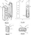
- Vehicle door assembly 50 represents an application of sensor 24 to an environment other than vehicle lift gate assemblies.
- Assembly 50 includes an interior door fascia 52 and a series of sensors 24.
- FIG. 5 illustrates a perspective view of vehicle door assembly 50 and
- FIG. 6 illustrates a cross-sectional view of the arrangement of sensors 24.
- Sensors 24 of vehicle door assembly 50 are each formed by their own conductor and are not directly electrically connected to one another. As such, each sensor 24 defines a unique touch pad associated with a unique touch area in which object detection of one sensor 24 does not depend on object detection of another sensor 24. Sensors 24 are arranged into an array and function independently of one another like an array of mechanical switches that commonly control vehicle functions like window up and down travel, door locking and unlocking, positioning of side view mirrors, etc.
- Interior door fascia 52 includes a pull handle 56 and a faceplate assembly 58 which together create an armrest component of door fascia 52.
- Sensors 24 are individually attached to the underside of faceplate assembly 58. Each sensor 24 has a sufficient area to detect a human finger proximal to that sensor. Object detection by a sensor 24 occurs when a portion of a user's body such as a hand or finger comes within sensitivity range directly over that sensor 24. By locating multiple sensors 24 on the underside of faceplate assembly 58, a sensor array is created to resemble the array of mechanical switches. Sensors 24 can be configured to have many different kinds of shapes such as raised surfaces or recessed contours to prevent accidental activation.
- Adding faceplate assembly 58 to the reversing control of a power window reduces complexity and cost associated with mechanical switches and associated wiring.
- the power window control for up/down can be incorporated into faceplate assembly 58 or the control can be remote if required due to vehicle design and packaging.
- a second sensor 24a placed on the external surface of the hatch (i.e., lift gate 12) of the vehicle can be used as an interface to operate the hatch. Additionally, a single controller can be used to interface with both anti-entrapment sensor 24 and hatch operating sensor 24a.
- faceplate assembly 58 includes a faceplate 60 made of electrically non-conductive material.
- Faceplate 60 provides support for multiple sensors 24 mounted to its underside (i.e., underside faceplate surface 63) and allows for object detection through its topside (i.e., topside faceplate surface 62).
- Underside faceplate surface 63 is relatively smooth to permit close mounting of sensors 24 to faceplate 60.
- degrees of roughness can also be configured to function effectively.
- Topside faceplate surface 62 can have any number of physical features 64 or graphical markings which are respectively associated (e.g., aligned) with sensors 24 in order to assist a user in locating the position of each sensor 24 and identifying the function assigned therewith.
- Each sensor 24 is formed as a thin electrically conductive pad mounted firmly to underside faceplate surface 63. Each sensor 24 in this configuration is pliable and can therefore be formed to the contours of the surface of faceplate 60 to which the sensor is attached. An adhesive may be applied between sensors 24 and the surface of faceplate 60 for positioning and support as well as minimizing air gaps between sensors 24 and the faceplate surface. Alternatively, sensors 24 can be molded into faceplate 60 thereby eliminating the need for adhesive or other mechanical attachment. Another alternate is each sensor 24 being arranged as a member mounted directly on a printed circuit board (PCB) 66 (i.e., a controller) and extending up toward, and possibly contacting, underside faceplate surface 63. With this arrangement, sensors 24 can be in direct physical and electrical contact with PCB 66 or in indirect contact with PCB 66 through the use of a joining conductor.
- PCB printed circuit board
- Each sensor 24 can be constructed of an electrically conductive material such as foam, metal, conductive plastic, or a non-conductive element with a conductive coating applied thereon.
- Materials used to construct sensors 24 should be of a compressible nature to account for tolerance stack-ups that are a normal part of any assembly having more than one component. Sensor compressibility ensures that contact is maintained between faceplate 60 and PCB 66. In the event that faceplate 60 is to be backlit, the use of a light pipe with conductive coating applied could be configured as a sensor 24.
- Sensors 24 can be constructed from materials having low electrical resistance such as common metals like copper or aluminum. Other materials exhibiting low electrical resistance such as conductive plastics, epoxies, paints, inks, or metallic coatings can be used. Sensors 24 can be preformed to resemble decals, emblems, stickers, tags, and the like. Sensors 24 can be applied onto surfaces as coatings or etched from plated surfaces. If materials are delicate, then a non-conductive backing 68 such as polyester film, fiberglass, paper, rubber, or the like can support and protect sensors 24 during installation. In applications where multiple sensing areas are required, backing 68 can assist in locating and anchoring sensors 24 to faceplate 60.
- a non-conductive backing 68 such as polyester film, fiberglass, paper, rubber, or the like can support and protect sensors 24 during installation. In applications where multiple sensing areas are required, backing 68 can assist in locating and anchoring sensors 24 to faceplate 60.
- backing 68 is a flexible circuit having copper pads which make up the touch pads of sensors 24 (i.e., each sensor 24 includes a copper pad).
- Backing 68 includes separated copper wires electrically connected to respective sensors 24 (shown in FIG. 7B ).
- Backing 68 makes an electrical connection to PCB 66 such that each sensor 24 is electrically connected to the signal conditioning electronics of PCB 66.
- backing 68 and PCB 66 are combined into a single circuit board containing both the touch pads of sensors 24 and the signal conditioning electronics.
- a user applies a finger to the associated marking 64 on the surface of faceplate 60.
- Electronic signal conditioning circuitry of PCB 66 which is interfaced to sensor 24 then processes the input signal from sensor 24 and completes circuit connections to activate the commanded function. The action is similar to pressing a mechanical switch to complete an electrical circuit.
- Sensors 24 can be applied to the backside of virtually any non-conductive barrier and preferably are flexible enough to conform to complex geometries where operator switch functions are needed. Sensors 24 can be contoured and configured from more rigid materials if desired. Examples of switch locations in a vehicle are door panels, armrests, dashboards, center consoles, overhead consoles, internal trim panels, exterior door components, and the like. Sensors 24 can be arranged individually or grouped as keypad arrays. Sensors 24 can be arranged into patterns of sequential sensing elements which are either electrically discrete or interconnected to create ergonomically appealing interfaces.
- Vehicle keyless entry assembly 70 represents an example of an automotive application incorporating sensors 24. Sensors 24 of vehicle keyless entry assembly 70 function as touch pads to activate a vehicle keyless entry.
- vehicle keyless entry assembly 70 includes a faceplate 60, a backing 68, and a PCB 66 (i.e., a controller). Sensors 24 with backing 68 are configured as a flexible circuit which uses individual conductive coatings for the touch pads of sensors 24. Backing 68 makes respective electrical connections between sensors 24 and the signal conditioning electronics on PCB 66.
- Vehicle keyless entry assembly 70 represents an example of a product requiring backlighting.
- sensors 24 have to be capable of passing light.
- faceplate 60 in this configuration is a molded transparent or translucent non-conductive material such as GE Plastics Lexan® 141 grade polycarbonate.
- PCB 66 has light sources 67 for illumination. Light sources 67 are positioned on respective portions of PCB 66 to be adjacent to corresponding ones of sensors 24. Other resins or materials meeting the application requirements including acceptable light transmittance characteristics can also be used for faceplate 60.
- Sensors 24 are attached to the underside 68a of backing 68. In turn, the topside 68b of backing 68 is attached to the interior surface of faceplate 60 using adhesive 72.
- the topside 68b of backing 68 has graphic characters 64 that locate the position of associated sensors 24 and identify the function assigned therewith.
- Either the underside 68a or the topside 68b of backing 68 has individual traces 74 for making an electrical connection between sensors 24 and PCB 66. Connection between backing 68 and PCB 66 is connected by a flat cable 76 which contains traces 74. This interconnect can be accomplished using other carriers such as individual wires, header style connectors, and the like.
- sensors 24 can be applied directly to the surface which is to be touched for activation. However, sensors 24 are on the backside of the touch surface for protection and wear resistance.
- Each sensor 24 of vehicle keyless entry assembly 70 may be made from Indium Tin Oxide (ITO) which is optically transparent and electrically conductive with an electrical resistance measuring sixty ohms/sq.
- ITO Indium Tin Oxide
- Other electrically conductive materials such as foam, elastomer, plastic, or a nonconductive structure with a conductive coating applied thereon can be used to produce a sensor 24 having transparent or translucent properties and being electrically conductive.
- Conductive materials that are opaque such as metal, plastic, foam, elastomer, carbon inks, or other coatings can be hollowed to pass light where desired while the remaining perimeter of material acts as sensor 24.
- An optically transparent and an electrically conductive sensor 24 made from ITO may create a color shift as light travels through the sensor and through the faceplate to which the sensor is attached. This color shift is a result of the optical quality and reflection of the optical distance between the front ITO surface of the sensor and the rear ITO surface of the sensor.
- a transparent coating is applied on the rear ITO surface to initially bend the light which thereby eliminates the color differential seen on the front surface of the sensor between the front and rear ITO surfaces of the sensor.
- an acrylic coating may be applied on the sensor to provide a layer of protection and durability for exposed ITO.
- a second sensor 24a placed on the external surface of a vehicle opening such as a hatch (i.e., lift gate 12) can be used as an interface to operate the vehicle opening.
- a keyless entry assembly includes a sensor like any of sensors 24 described herein which is to be placed on the external surface of a vehicle opening and is to be used as an interface to operate (i.e., open and close; unlock and lock) the vehicle opening.
- the vehicle opening may be a door, a trunk lid, or any other opening of a vehicle and may be of a metal construction.
- this keyless entry assembly includes a sensor 24 which is placed on the external side of the trunk lid and arranged behind a non-conductive barrier like faceplate 60.
- This keyless entry assembly further includes a controller in addition to sensor 24.
- the controller is operable to unlock the trunk lid.
- the controller is in communication with sensor 24 to monitor the capacitance of sensor 24 in order to determine whether an object (including a human user) is touching sensor 24 or whether an electrically conductive object (such as the user) is in proximity to sensor 24. If the controller determines that a user is touching or is in proximity to sensor 24, then the controller deduces that the user is at least in proximity to the trunk lid. Upon deducing that a user is at least in proximity to the trunk lid, the controller controls the trunk lid accordingly. For instance, while the trunk lid is closed and a user touches or comes into proximity to the trunk lid, the controller unlocks the trunk lid. In turn, the user can open the trunk lid (or the trunk lid can be opened automatically) to access the trunk.
- this keyless entry assembly can be realized by touch or touchless activation for releasing the trunk lid.
- touch activation is a user touching sensor 24.
- touchless activation is a user moving into proximity to sensor 24.
- another example of touchless activation is a sequence of events taking place such as a user approaching sensor 24 and then stepping away in a certain amount of time.
- this keyless entry assembly may include a mechanism for detecting the authorization of the user to activate the trunk lid.
- the controller is operable for key fob querying and the user is to possess a key fob in order for the controller to determine the authorization of the user in a manner known by those of ordinary skill in the art. That is, the user is to be in at least proximity to the trunk lid and be in possession of an authorized key fob (i.e., the user has to have proper identification) before touch or touchless activation is provided.
- a user having a key fob approaches a trunk lid on which sensor 24 is placed.
- the user touches or comes into proximity to sensor 24.
- the controller determines that an object is touching or is in proximity to the trunk lid based on the resulting capacitance of sensor 24.
- the controller transmits a key fob query to which the key fob responds. If the response is what the controller expected (i.e., the key fob is an authorized key fob), then the controller unlocks the trunk lid for the user to gain access to the trunk. On the other hand, if there is no response or if the response is not what the controller expected (i.e., the key fob is an unauthorized key fob), then the controller maintains locking of the trunk lid.
- sensor 24 may be in the form of an emblem, decal, logo, or the like (e.g., "emblem") in a manner as described herein.
- an emblem i.e., sensor 24
- emblem 24 may have different structures, forms, and characteristics depending on manufacturer and model of the vehicle.
- sensor 24 of this keyless entry assembly may be capable of passing light in a manner as described herein. Accordingly, this keyless entry assembly may further include a light source, such as any of light sources 67, which is associated with sensor 24. In this event, the controller is operable for controlling the light source in order to illuminate sensor 24 (i.e., illuminate the emblem).
- a light source such as any of light sources 67
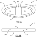
- FIGS. 8A and 8B illustrate various views of such a keyless entry assembly 80 in accordance with an embodiment of the present invention.
- Keyless entry assembly 80 includes a sensor assembly 82 and a controller (not shown).
- the controller is in communication with sensor assembly 82 and is operable for controlling vehicle functions such as locking and unlocking a vehicle opening (e.g., a trunk lid of a vehicle).
- FIG. 8A is a view looking at sensor assembly 82 while sensor assembly 82 is placed on the external surface of the trunk lid.
- FIG. 8B is a view looking through a cross-section of sensor assembly 82.
- Sensor assembly 82 includes two sensors (i.e., first sensor 24a and second sensor 24b). First sensor 24a is labeled in FIG. 8B as "S1" and second sensor 24b is labeled in FIG. 8B as "S2".
- Sensors 24a, 24b are respectively located at different portions of sensor assembly 82. For instance, as shown in FIGS. 8A and 8B , first sensor 24a is at a lefthand side of sensor assembly 82 and second sensor 24b is at a right-hand side of sensor assembly 82.
- Sensors 24a, 24b are electrically connected to or associated with a PCB in a manner as described herein. As such, sensors 24a, 24b are not electrically connected to one another. First sensor 24a activates when an object is in proximity to first sensor 24a and second sensor 24b activates when an object is in proximity to second sensor 24b. Similarly, only first sensor 24a activates when an object is in proximity to first sensor 24a and not to second sensor 24b. Likewise, only second sensor 24b activates when an object is in proximity to second sensor 24b and not to first sensor 24a. The activation of a sensor like sensors 24a, 24b depends on the capacitance of the sensor as a result of an object coming into at least proximity with the sensor. For instance, when an object is in proximity to both sensors 24a, 24b and is closer to first sensor 24a than to second sensor 24b, then first sensor 24a will have a stronger activation than second sensor 24b.
- Sensor assembly 82 further includes a non-conductive barrier 84 like faceplate 60. Sensors 24a, 24b are mounted to the underside of faceplate 84. Faceplate 84 allows for object detection through its topside. Sensor assembly 82 further includes an overlay 86 positioned over faceplate 84. Overlay 86 is in the shape of an emblem or logo representing the vehicle. In this example, overlay 86 includes two cut-out portions at which sensors 24a, 24b are respectively located. As such, sensors 24a, 24b are patterned to conform to the emblem arrangement of overlay 86.
- Keyless entry assembly 80 is an example of the use of sensors (i.e., sensor assembly 82) in conjunction with a controller for operating a trunk lid when a user is in proximity to or is touching sensor assembly 82. As described herein, the operation of the trunk lid may further depend on the authenticity of the user (i.e., whether the user is in possession of an authorized key fob). In the manner described above, sensor assembly 82 can be used to realize either touch or touchless activation for releasing the trunk lid. In terms of touchless activation, sensor assembly 82 represents an example of a handsfree virtual proximity switch.
- a particular application of sensor assembly 82 realizing touchless activation involves a sequence of user events taking place relative to sensor assembly 82 in order to control operation of the trunk lid.
- the controller of keyless entry assembly 80 may be configured such that a user is required to approach sensor assembly 82 and then step back from sensor assembly 82 in a certain amount of time in order for the controller to unlock the trunk lid.
- Such a sequence of user events are effectively user body gestures.
- an expected sequence of user body gestures effectively represents a virtual code for unlocking the trunk lid. That is, the controller controls unlocks the trunk lid in response to a user performing an expected sequence of body gestures in relation to sensor assembly 82.
- the user may or may not be required to have an authorized key fob depending on whether possession of an authorized key fob is required to unlock the trunk lid.
- a more elaborate example of an expected sequence of user body gestures includes the user starting in proximity to sensor assembly 82, then moving backward, then moving left, then moving right, etc.
- another example of an expected sequence of includes the user starting in proximity to sensor assembly 82, then moving away, then moving close, etc. The steps of either sequence may be required to occur within respective time periods.
- different expected sequences of user body gestures effectively represent different virtual codes for controlling the trunk lid.
- Keyless entry assembly 80 provides the user the opportunity to 'personalize' sensor assembly 82 in order to program the controller with the expected sequence of user body gestures that are to be required to control the trunk lid.
- Personalizing sensor assembly 82 with an expected sequence of user body gestures effectively provides a virtual code to the controller which is to be subsequently entered by the user (by subsequently performing the expected sequence of user body gestures) for the controller to unlock the trunk lid.
- sensors 24a, 24b activate differently from one another as a function of the proximity of the user to that particular sensor.
- each sensor 24a, 24b activates when a user is in proximity to that sensor and each sensor 24a, 24b is not activated when a user in not in proximity to that sensor.
- sensors 24a, 24b activate when a user is in proximity to sensors 24a, 24b (which happens when a user steps into proximity of both sensors 24a, 24b).
- sensors 24a, 24b are not activated when the user is out of proximity to sensors 24a, 24b (which happens when a user steps back far enough away from sensors 24a, 24b).
- the amount of activation of a sensor depends on the proximity of a user to the sensor. For instance, first sensor 24a has a stronger activation than second sensor 24b when the user is in closer proximity to first sensor 24a than to second sensor 24b. As such, in this event, the controller determines that the user is closer to first sensor 24a than to second sensor 24b. That is, the controller determines that the user has stepped to the left after the user initially was initially in proximity to sensor assembly 82. Likewise, second sensor 24b has a stronger activation than first sensor 24a when the user is in closer proximity to second sensor 24b than to first sensor 24a. As such, in this event, the controller determines that the user is closer to second sensor 24b than to first sensor 24a. That is, the controller determines that the user has stepped to the right after the user initially was in proximity to sensor assembly 82.
- sensor assembly 82 further includes a plurality of light sources 88 such as light-emitting diodes (LEDs).
- LEDs 88 are electrically connected to the PCB to which sensors 24a, 24b are electrically connected.
- LEDs 88 are mounted to the underside of faceplate 84 where overlay 86 is absent or, alternatively, LEDs 88 are mounted to the underside of faceplate 84 where overlay is present (as shown in FIG. 8A ).
- faceplate 84 is clear such that light from LEDs 88 can pass through faceplate 84.
- overlay 86 has cutouts dimensioned to the size of LEDs 88 and LEDs 88 are respectively positioned adjacent to these cutouts such that light from LEDs 88 can pass through faceplate 84 and overlay 86.
- the controller is configured to control LEDs 88 to light on or off depending on activation of sensors 24a, 24b.
- the controller controls LEDs 88 such that: LEDs 88a, 88b, 88c light on when both sensors 24a, 24b are activated; LEDs 88a, 88b, 88c light off when both sensors 24a, 24b are not activated; first LED 88a lights on when first sensor 24a is activated and lights off when first sensor 24a is not activated; and third LED 88c lights on when second sensor 24b is activated and lights off when second sensor 24b is not activated;.
- the controller controls LEDs such that: LEDs 88a, 88b, 88c light on when a user is in proximity to both sensors 24a, 24b (which occurs when the user steps close to sensor assembly 82) 24b); LEDs 88a, 88b, 88c light off when the user is out of proximity to both sensors 24a, 24b (which occurs when the user steps far enough back away from sensor assembly 82); first LED 88a lights on and second and third LEDs 88b, 88c light off when the user is in proximity to first sensor 24a and is no closer than tangential proximity to second sensor 24b (which occurs when the user steps to the left while in proximity to sensor assembly 82); and third LED 88c lights on and first and second LEDs 88a, 88b light off when the user is in proximity to second sensor 24b and is no closer than tangential proximity to first sensor 24a (which occurs when the user steps to the right while in proximity to sensor assembly 82).
- the user can use the lighting of LEDs 88a, 88b, 88c as feedback when performing a sequence of user body gestures relative to sensor assembly 82 in order to either program (personalize) sensor assembly 82 with the sequence of user body gestures or to unlock the trunk lid by performing the sequence of user body gestures.
Landscapes
- Engineering & Computer Science (AREA)
- Human Computer Interaction (AREA)
- Mechanical Engineering (AREA)
- Lock And Its Accessories (AREA)
Claims (7)
- Schlüssellose Zugangsbaugruppe (10, 20, 40, 70, 80) mit:einer Fahrzeugöffnung, die zwischen einer verschlossenen Stellung und einer geöffneten Stellung bewegt werden kann,einem elektrischen Leiter, der auf einer äußeren Oberfläche der Fahrzeugöffnung montiert ist, wobei der Leiter mit einem elektrisch leitenden Objekt in der Nähe des Leiters koppelt, während der Leiter mit einer elektrischen Ladung beaufschlagt ist, derart, dass sich die Kapazität des Leiters ändert aufgrund der kapazitiven Kopplung des Leiters mit dem Objekt,dadurch gekennzeichnet, dass der Leiter selbst in Form eines Symbols geformt ist, das ein Fahrzeug identifiziert, welches mit der Fahrzeugöffnung in Zusammenhang zu bringen ist, und eine elektrisch nicht-leitende Abdeckung, einen Überzug in Form des Symbols, welcher über der Abdeckung positioniert ist und eine Mehrzahl von Aussparungen aufweist, und einer Mehrzahl von Sensoren, die an der Unterseite der Abdeckung montiert sind und in den Aussparungsbereichen gelegen sind und so angeordnet sind, dass sie mit der Symbolanordnung der Abdeckung übereinstimmen und nicht elektrisch miteinander verbunden sind, aufweist, undeine Steuereinheit zum Steuern des Leiters mit der elektrischen Ladung und zum Messen der Kapazität des Leiters, um zu bestimmen, ob sich ein elektrisch leitendes Objekt in der Nähe des Leiters befindet, wobei die Steuereinheit die Fahrzeugöffnung so steuern kann, dass die Fahrzeugöffnung aus einer der Stellungen in die andere der Stellungen bewegt wird, nachdem erfasst wurde, dass sich ein elektrisch leitendes Objekt in der Nähe des Leiters befindet.
- Schlüssellose Zugangsbaugruppe (10, 20, 40, 70, 80) nach Anspruch 1, dadurch gekennzeichnet, dass:die Steuereinheit ferner funktionsbereit ist für eine Schlüsselanhängerabfrage, wobei die Steuereinheit die Fahrzeugöffnung steuert, um die Fahrzeugöffnung von einer der Stellungen in die andere der Stellungen zu bewegen, nachdem erfasst wurde, dass ein elektrisch leitendes Objekt sich in der Nähe des Leiters befindet und dass sich ein berechtigter Schlüsselanhänger im Bereich der Steuereinheit befindet.
- Schlüssellose Zugangsbaugruppe (10, 20, 40, 70, 80) nach Anspruch 1, dadurch gekennzeichnet, dass:die Steuereinheit ferner betriebsbereit ist für die Beleuchtung des Leiters.
- Schlüssellose Zugangsbaugruppe (10, 20, 40, 70, 80) nach Anspruch 1, dadurch gekennzeichnet, dass:die Fahrzeugöffnung eine Fahrzeugtür, eine Fahrzeugheckklappe oder ein Fahrzeugkofferraumdeckel ist.
- Schlüssellose Zugangsbaugruppe (10, 20, 40, 70, 80) nach Anspruch 1, dadurch gekennzeichnet, dass:eine der Stellungen die verriegelte Stellung ist und die andere der Stellungen die unverriegelte Stellung ist.
- Schlüssellose Zugangsbaugruppe (10, 20, 40, 70, 80) nach Anspruch 1, dadurch gekennzeichnet, dass:die Fahrzeugöffnung eine Metallkonstruktion ist,der Leiter flexibel ist, derart, dass sich der Leiter auf die Fahrzeugöffnung zu bewegt, nachdem ein Objekt den Leiter in einer Richtung auf die Fahrzeugöffnung zu berührt,wobei der Leiter kapazitiv mit der Fahrzeugöffnung gekoppelt ist, während der Leiter mit der elektrischen Ladung beaufschlagt wird, derart, dass die Kapazität des Leiters sich dadurch ändert, dass der Leiter nach der Berührung des Leiters durch ein Objekt auf die Fahrzeugöffnung zu bewegt wird.
- Schlüssellose Zugangsbaugruppe (10, 20, 40, 70, 80) nach Anspruch 1, dadurch gekennzeichnet, dass:ein elektrisch nicht leitender komprimierbarer Abstandshalter vorgesehen ist, wobei der Abstandshalter zwischen dem Leiter und der äußeren Oberfläche der Fahrzeugöffnung angeordnet ist, wobei die Fahrzeugöffnung eine Metallkonstruktion aufweist,wobei der Abstandshalter sich auf die Fahrzeugöffnung zu komprimiert in Reaktion auf die Berührung des Leiters durch ein Objekt, derart, dass sich der Leiter auf die Fahrzeugöffnung zu bewegt, wobei der Leiter kapazitiv mit der Fahrzeugöffnung gekoppelt ist, während der Leiter mit der elektrischen Ladung beaufschlagt ist, derart, dass die Kapazität des Leiters sich dadurch ändert, dass der Leiter auf die Fahrzeugöffnung zu bewegt wird, nachdem das Objekt den Leiter berührt hat.
Applications Claiming Priority (3)
| Application Number | Priority Date | Filing Date | Title |
|---|---|---|---|
| US12/545,178 US9705494B2 (en) | 2009-08-21 | 2009-08-21 | Vehicle assemblies having fascia panels with capacitance sensors operative for detecting proximal objects |
| US12/784,010 US10017977B2 (en) | 2009-08-21 | 2010-05-20 | Keyless entry assembly having capacitance sensor operative for detecting objects |
| PCT/US2010/045729 WO2011022374A1 (en) | 2009-08-21 | 2010-08-17 | Keyless entry assembly having capacitance sensor operative for detecting objects |
Publications (3)
| Publication Number | Publication Date |
|---|---|
| EP2467760A1 EP2467760A1 (de) | 2012-06-27 |
| EP2467760A4 EP2467760A4 (de) | 2016-08-17 |
| EP2467760B1 true EP2467760B1 (de) | 2018-03-21 |
Family
ID=43604883
Family Applications (1)
| Application Number | Title | Priority Date | Filing Date |
|---|---|---|---|
| EP10810469.6A Not-in-force EP2467760B1 (de) | 2009-08-21 | 2010-08-17 | Tastenlose eingabevorrichtung mit kapazitätssensor zur objekterkennung |
Country Status (3)
| Country | Link |
|---|---|
| US (1) | US10017977B2 (de) |
| EP (1) | EP2467760B1 (de) |
| WO (1) | WO2011022374A1 (de) |
Families Citing this family (36)
| Publication number | Priority date | Publication date | Assignee | Title |
|---|---|---|---|---|
| US9845629B2 (en) | 2009-08-21 | 2017-12-19 | Uusi, Llc | Vehicle keyless entry assembly having capacitance sensor operative for detecting objects |
| US9705494B2 (en) * | 2009-08-21 | 2017-07-11 | Uusi, Llc | Vehicle assemblies having fascia panels with capacitance sensors operative for detecting proximal objects |
| US9051769B2 (en) | 2009-08-21 | 2015-06-09 | Uusi, Llc | Vehicle assembly having a capacitive sensor |
| US9199608B2 (en) * | 2009-08-21 | 2015-12-01 | Uusi, Llc | Keyless entry assembly having capacitance sensor operative for detecting objects |
| US10017977B2 (en) | 2009-08-21 | 2018-07-10 | Uusi, Llc | Keyless entry assembly having capacitance sensor operative for detecting objects |
| US11634937B2 (en) | 2009-08-21 | 2023-04-25 | Uusi, Llc | Vehicle assembly having a capacitive sensor |
| US9575481B2 (en) * | 2009-08-21 | 2017-02-21 | Uusi, Llc | Fascia panel assembly having capacitance sensor operative for detecting objects |
| US10954709B2 (en) | 2009-08-21 | 2021-03-23 | Uusi, Llc | Vehicle assembly having a capacitive sensor |
| JP6150073B2 (ja) * | 2012-02-03 | 2017-06-21 | 日本電気株式会社 | 電力需給調整システム |
| US10282034B2 (en) | 2012-10-14 | 2019-05-07 | Neonode Inc. | Touch sensitive curved and flexible displays |
| US9164625B2 (en) | 2012-10-14 | 2015-10-20 | Neonode Inc. | Proximity sensor for determining two-dimensional coordinates of a proximal object |
| US9741184B2 (en) | 2012-10-14 | 2017-08-22 | Neonode Inc. | Door handle with optical proximity sensors |
| US9921661B2 (en) | 2012-10-14 | 2018-03-20 | Neonode Inc. | Optical proximity sensor and associated user interface |
| US10324565B2 (en) | 2013-05-30 | 2019-06-18 | Neonode Inc. | Optical proximity sensor |
| US10585530B2 (en) | 2014-09-23 | 2020-03-10 | Neonode Inc. | Optical proximity sensor |
| KR101507068B1 (ko) * | 2013-07-10 | 2015-04-01 | (주) 모토텍 | 파워 트렁크 또는 파워 테일게이트 제어 시스템 |
| US9646436B1 (en) * | 2013-12-31 | 2017-05-09 | Huf North America Automotive Parts Manufacturing, Corp. | Gesture controls for remote vehicle access systems |
| DE102014101195A1 (de) * | 2014-01-31 | 2015-08-06 | Huf Hülsbeck & Fürst Gmbh & Co. Kg | Montagemodul für ein Kraftfahrzeug |
| DE102014101198A1 (de) * | 2014-01-31 | 2015-08-06 | Huf Hülsbeck & Fürst Gmbh & Co. Kg | Emblem für ein Kraftfahrzeug mit einem optischen Sensorsystem sowie Verfahren hierzu |
| US9694735B2 (en) * | 2015-01-26 | 2017-07-04 | Flextronics International Usa, Inc. | Vehicle emblem incorporating capacitive switch and LED lighting |
| DE102015208611A1 (de) * | 2015-05-08 | 2016-11-10 | Volkswagen Aktiengesellschaft | Betätigung eines Schließelements eines Fahrzeugs mit Ultraschallsensor |
| US9797178B2 (en) * | 2015-07-29 | 2017-10-24 | Ford Global Technologies, Llc | Seal based object detection for vehicle door assist system |
| KR101976419B1 (ko) * | 2016-03-18 | 2019-05-09 | 엘지전자 주식회사 | 차량용 도어 제어 장치 및 차량 |
| US20180367139A1 (en) * | 2017-06-15 | 2018-12-20 | Magna Closures Inc. | User interface system for controlling a vehicle operation |
| US11054514B2 (en) * | 2017-11-22 | 2021-07-06 | Magna Closures Inc. | Radar beam forming shield for motor vehicle |
| DE102019202259A1 (de) * | 2019-02-20 | 2020-08-20 | Psa Automobiles Sa | Betätigungseinrichtung für den Kraftfahrzeugaußenbereich |
| JP7221738B2 (ja) * | 2019-03-05 | 2023-02-14 | 株式会社アイシン | 車両用操作検出装置 |
| CN115039060A (zh) | 2019-12-31 | 2022-09-09 | 内奥诺德公司 | 非接触式触摸输入系统 |
| CN111332219A (zh) * | 2020-01-17 | 2020-06-26 | 东风延锋汽车饰件系统有限公司 | 一种带智能触控的内饰件 |
| CN112049538B (zh) * | 2020-08-24 | 2021-11-02 | 安徽安凯汽车股份有限公司 | 一种客车乘客门防夹功能电源智能控制系统 |
| US11702880B2 (en) | 2020-08-27 | 2023-07-18 | Extang Corporation | Capacitive touch vehicle accessory |
| KR20220033772A (ko) * | 2020-09-10 | 2022-03-17 | 현대모비스 주식회사 | 차량용 후방카메라 및 그 제어방법 |
| US11898396B2 (en) | 2021-01-25 | 2024-02-13 | Uusi, Llc | System and method for detecting operator characteristic to adjust position of power actuated movable panel |
| US20220333429A1 (en) * | 2021-04-15 | 2022-10-20 | Dus Operating Inc. | Sensor assembly for a liftgate opening system of a rear liftgate of a motor vehicle |
| US11725451B2 (en) * | 2021-04-26 | 2023-08-15 | Ford Global Technologies, Llc | Systems and methods of interior sensor-based vehicle liftgate actuation |
| DE102023128663A1 (de) | 2022-10-25 | 2024-04-25 | Uusi, Llc | Fahrzeuganordnung mit einem kapazitiven sensor |
Family Cites Families (116)
| Publication number | Priority date | Publication date | Assignee | Title |
|---|---|---|---|---|
| US2476111A (en) | 1945-07-07 | 1949-07-12 | Opalek Charles | Mechanism for automatic stopping and reversal of electromechanically operated doors |
| US3830018A (en) | 1970-02-17 | 1974-08-20 | Toyota Motor Co Ltd | Safety device for power window |
| US3855733A (en) | 1973-06-27 | 1974-12-24 | Miller Bros | Sensitive edge for a door |
| US4178621A (en) | 1978-01-23 | 1979-12-11 | Motorola, Inc. | Electromechanical pressure transducer |
| DE3111724A1 (de) | 1981-03-25 | 1982-10-07 | FHN-Verbindungstechnik GmbH, 8501 Eckental | "automatisch versenkbares kraftfahrzeugfenster" |
| JPS57191121A (en) | 1981-05-20 | 1982-11-24 | Nissan Motor Co Ltd | Safety device in auto door |
| AT391913B (de) | 1988-03-18 | 1990-12-27 | Setec Messgeraete Gmbh | Einklemmschutz fuer fenster und tueren |
| US4933807A (en) | 1989-08-23 | 1990-06-12 | Key Concepts, Inc. | Method of and apparatus for improved capacitive displacement and pressure sensing including for electronic musical instruments |
| US5394292A (en) | 1991-04-30 | 1995-02-28 | Tsuden Kabushiki Kaisha | Electronic car bumper |
| US5952801A (en) | 1992-04-22 | 1999-09-14 | Nartron Corporation | Power window or panel controller |
| US6404158B1 (en) | 1992-04-22 | 2002-06-11 | Nartron Corporation | Collision monitoring system |
| US7084859B1 (en) | 1992-09-18 | 2006-08-01 | Pryor Timothy R | Programmable tactile touch screen displays and man-machine interfaces for improved vehicle instrumentation and telematics |
| US5361018A (en) | 1993-08-09 | 1994-11-01 | Milton Richard M | Intermediate voltage cable marker with enhanced conspicuity |
| US5493277A (en) | 1993-09-08 | 1996-02-20 | Pierce; Lindy | Device for monitoring the water level of a container and for adding water to the container |
| US5621290A (en) | 1993-10-18 | 1997-04-15 | Draftex Industries Limited | Movable-window safety device |
| DE19509282A1 (de) | 1995-03-15 | 1996-11-14 | Brose Fahrzeugteile | Fahrzeugtür |
| US5801340A (en) | 1995-06-29 | 1998-09-01 | Invotronics Manufacturing | Proximity sensor |
| US5730165A (en) | 1995-12-26 | 1998-03-24 | Philipp; Harald | Time domain capacitive field detector |
| DE19720713C1 (de) | 1997-05-16 | 1998-05-28 | Metzeler Automotive Profiles | Dichtungsprofil zur Abdichtung einer kraftbetätigten Schließeinrichtung |
| US5959538A (en) | 1997-10-15 | 1999-09-28 | Vital Innovations, Inc. | Force sensing resistor conditioning circuit |
| GB9724542D0 (en) | 1997-11-21 | 1998-01-21 | Philipp Harald | Electronic Smart Hammer |
| US8479122B2 (en) | 2004-07-30 | 2013-07-02 | Apple Inc. | Gestures for touch sensitive input devices |
| JP2000177392A (ja) | 1998-12-16 | 2000-06-27 | Aisin Seiki Co Ltd | スライドドア給電機構 |
| US6389752B1 (en) | 1999-06-21 | 2002-05-21 | Schlegel Corporation | Touch sensitive trapping protector for power operated closing devices |
| US6377009B1 (en) | 1999-09-08 | 2002-04-23 | Harald Philipp | Capacitive closure obstruction sensor |
| US6431638B1 (en) | 1999-11-15 | 2002-08-13 | The Budd Company | Automobile lift gate |
| DE10107319A1 (de) | 2000-02-18 | 2002-01-31 | Aisin Seiki | Rahmenantennenvorrichtung |
| US6337549B1 (en) | 2000-05-12 | 2002-01-08 | Anthony Gerald Bledin | Capacitive anti finger trap proximity sensor |
| US6825752B2 (en) * | 2000-06-13 | 2004-11-30 | Siemens Vdo Automotive Corporation | Effortless entry system and method |
| JP2004506110A (ja) | 2000-08-03 | 2004-02-26 | アトマ インターナショナル コーポレイション | 非接触センサを有する乗物閉止はさみ防止組立体 |
| US6498214B2 (en) | 2000-08-22 | 2002-12-24 | Dupont Dow Elastomers L.L.C. | Soft touch TPO compositions comprising polypropylene and low crystalline ethylene copolymers |
| FR2817663B1 (fr) * | 2000-12-01 | 2004-02-27 | Valeo Electronique | Dispositif de detection tactile pour vehicule automobile |
| US7126453B2 (en) | 2001-02-21 | 2006-10-24 | Kiekert Ag | Keyless system for actuating a motor-vehicle door latch |
| FR2823163B1 (fr) | 2001-04-04 | 2003-07-04 | Plastic Omnium Cie | Element exterieur de vehicule automobile, integrant un capteur capacitif et piece de carrosserie comportant un tel element exterieur |
| US6555982B2 (en) | 2001-05-29 | 2003-04-29 | Meritor Light Vehicle Technology, L.L.C. | Method and system for detecting an object in the path of an automotive window utilizing a system equation |
| JP2005501375A (ja) | 2001-06-08 | 2005-01-13 | インティアー オートモーティヴ クロージャーズ インコーポレイテッド | 非接触近接センサ |
| JP3566943B2 (ja) | 2001-07-02 | 2004-09-15 | アイシン精機株式会社 | 車両用ドアハンドル |
| US7132642B2 (en) | 2001-07-09 | 2006-11-07 | Nartron Corporation | Anti-entrapment systems for preventing objects from being entrapped by translating devices |
| US7293467B2 (en) | 2001-07-09 | 2007-11-13 | Nartron Corporation | Anti-entrapment system |
| US6499359B1 (en) | 2001-07-09 | 2002-12-31 | Nartron Corporation | Compressible capacitance sensor for determining the presence of an object |
| US7162928B2 (en) | 2004-12-06 | 2007-01-16 | Nartron Corporation | Anti-entrapment system |
| US6782759B2 (en) | 2001-07-09 | 2004-08-31 | Nartron Corporation | Anti-entrapment system |
| US7424347B2 (en) | 2001-07-19 | 2008-09-09 | Kelsey-Hayes Company | Motion sensors integrated within an electro-hydraulic control unit |
| DE10238020A1 (de) | 2001-08-23 | 2004-03-04 | Brose Fahrzeugteile Gmbh & Co. Kommanditgesellschaft, Coburg | Kraftfahrzeug-Baugruppe |
| US6689970B2 (en) | 2001-10-04 | 2004-02-10 | Lester E. Burgess | Pressure actuated switching device and method and system for making same |
| US6750624B2 (en) * | 2001-10-17 | 2004-06-15 | Delphi Technologies, Inc. | Non-contact obstacle detection system utilizing ultra sensitive capacitive sensing |
| US6723933B2 (en) | 2001-10-17 | 2004-04-20 | Ronald Helmut Haag | Flexible capacitive strip for use in a non-contact obstacle detection system |
| US6700393B2 (en) | 2001-10-17 | 2004-03-02 | Delphi Technologies, Inc. | Capacitive sensor assembly for use in a non-contact obstacle detection system |
| DE10297401T5 (de) | 2001-11-02 | 2004-09-16 | Intier Automative Closures Inc. | Kapazitive Mehrbereichs-Klemmschutzanordnung |
| DE10220725C1 (de) | 2002-05-07 | 2003-04-03 | Metzeler Automotive Profile | Vorrichtung zum Erkennen eines Hindernisses in dem Öffnungsbereich eines bewegbaren Schließelements eines Kraftfahrzeugs |
| US20030216817A1 (en) * | 2002-05-16 | 2003-11-20 | Richard Pudney | Vehicle access system with sensor |
| DE10226133A1 (de) | 2002-06-12 | 2004-01-08 | Metzeler Automotive Profile Systems Gmbh | Anordnung für eine Vorrichtung zum Erkennen eines Hindernisses in dem Öffnungsbereich eines bewegbaren Schließelements eines Kraftfahrzeugs |
| CA2444670A1 (en) | 2002-09-27 | 2004-03-27 | Litens Automotive | Low-mounted powered opening system and control mechanism |
| JP3831325B2 (ja) | 2002-10-01 | 2006-10-11 | アスモ株式会社 | 開閉装置 |
| DE60215504T2 (de) | 2002-10-07 | 2007-09-06 | Sony France S.A. | Verfahren und Gerät zur Analyse von Gesten eines Menschen, z.B. zur Steuerung einer Maschine durch Gestik |
| DE10250395A1 (de) | 2002-10-29 | 2004-05-13 | BSH Bosch und Siemens Hausgeräte GmbH | Kapazitiver Annäherungs- und/oder Berührungssensor sowie elektrisch leitfähiger Kunststoffkörper für einen solchen Sensor |
| US7424377B2 (en) | 2002-11-04 | 2008-09-09 | Neptune Technology Group, Inc. | Power reduction method in an electronic counter |
| JP4009953B2 (ja) * | 2003-05-14 | 2007-11-21 | オムロン株式会社 | 物体検知センサ |
| TWM246202U (en) * | 2003-05-20 | 2004-10-11 | Exon Science Inc | Vehicular door handle module |
| US7226112B2 (en) | 2003-10-02 | 2007-06-05 | Nicholas Plastics Incorporated | Pinch warning and illumination system |
| GB0325075D0 (en) | 2003-10-28 | 2003-12-03 | Ford Global Tech Llc | Control system |
| DE102004002415B4 (de) | 2004-01-16 | 2008-07-10 | Metzeler Automotive Profile Systems Gmbh | Vorrichtung zum Steuern und Überwachen eines bewegbaren Schliesselements, insbesondere einer elektrisch angetriebenen Fensterscheibe eines Kraftfahrzeugs |
| US7116117B2 (en) | 2004-02-16 | 2006-10-03 | Honda Motor Co., Ltd. | Capacitive sensor |
| US6980095B2 (en) | 2004-03-17 | 2005-12-27 | Lear Corporation | Illuminated vehicle remote entry device |
| US7706046B2 (en) | 2004-06-08 | 2010-04-27 | Gentex Corporation | Rearview mirror element having a circuit mounted to the rear surface of the element |
| JP4257601B2 (ja) * | 2004-06-24 | 2009-04-22 | アイシン精機株式会社 | 車両用ドア開閉装置 |
| US7911321B2 (en) | 2004-10-26 | 2011-03-22 | Adac Plastics, Inc. | Keyless entry system incorporating concealable keypad |
| US7576631B1 (en) | 2004-10-26 | 2009-08-18 | Adac Plastics, Inc. | Vehicular keyless entry system incorporating textual representation of the vehicle or user of the vehicle |
| EP1795674A1 (de) | 2004-12-08 | 2007-06-13 | Matsushita Electric Industrial Co., Ltd. | Türgriffvorrichtung, türglied mit der türgriffvorrichtung und intelligentes eintrittssystem mit dem türglied |
| DE112005003178T5 (de) | 2004-12-17 | 2008-02-14 | Stoneridge Control Devices, Inc., Canton | Berührungssensorvorrichtung und Verfahren |
| MX2007007689A (es) | 2004-12-23 | 2007-09-07 | Touchsensor Tech Llc | Sistema de control de asientos. |
| US7248151B2 (en) | 2005-01-05 | 2007-07-24 | General Motors Corporation | Virtual keypad for vehicle entry control |
| US7312591B2 (en) | 2005-03-11 | 2007-12-25 | Npc Corporation | Powered panel moving system |
| US7255466B2 (en) | 2005-05-17 | 2007-08-14 | Lear Corporation | Illuminated keyless entry control device |
| US7354097B2 (en) | 2005-05-25 | 2008-04-08 | Gm Global Technology Operations, Inc. | Power-actuated closure system |
| DE102005038617A1 (de) | 2005-08-16 | 2007-03-01 | Webasto Ag | Einklemmschutzvorrichtung im Kraftfahrzeugbereich |
| US7219945B1 (en) | 2005-10-26 | 2007-05-22 | Ford Global Technologies, Llc | Power lift gate for automotive vehicle |
| US7538672B2 (en) | 2005-11-01 | 2009-05-26 | Savi Technology, Inc. | Method and apparatus for capacitive sensing of door position |
| US7635210B2 (en) | 2005-12-23 | 2009-12-22 | Ford Global Technologies, Llc | Illuminated door handle |
| US7342373B2 (en) | 2006-01-04 | 2008-03-11 | Nartron Corporation | Vehicle panel control system |
| WO2007096746A2 (en) | 2006-02-21 | 2007-08-30 | System S.P.A. | Decorating with powder material |
| DE102006009998B4 (de) | 2006-03-03 | 2014-12-24 | Webasto Ag | Motorisch betätigbares Bauteil mit Einklemmschutz |
| DE102006022610B4 (de) | 2006-05-15 | 2008-05-08 | Siemens Ag | Sicherheitsanordnung in einem oder für ein Fahrzeug und Kraftfahrzeug |
| US7547058B2 (en) | 2006-05-15 | 2009-06-16 | Ford Global Technologies, Llc | System and method for operating an automotive liftgate |
| JP4828467B2 (ja) | 2006-05-18 | 2011-11-30 | 西川ゴム工業株式会社 | 自動車の開閉扉挟み込み防止センサー |
| US7688013B2 (en) | 2006-06-21 | 2010-03-30 | Flextronics Automotive Inc. | System and method for controlling speed of a closure member |
| JP4827644B2 (ja) | 2006-07-27 | 2011-11-30 | アルパイン株式会社 | 遠隔用入力装置およびこれを用いた電子装置 |
| DE202006013337U1 (de) | 2006-08-30 | 2008-01-03 | Brose Fahrzeugteile Gmbh & Co. Kommanditgesellschaft, Coburg | Einklemmschutz |
| DE202006013335U1 (de) | 2006-08-30 | 2008-01-03 | Brose Fahrzeugteile Gmbh & Co. Kommanditgesellschaft, Coburg | Einklemmschutzvorrichtung |
| US7989725B2 (en) | 2006-10-30 | 2011-08-02 | Ink-Logix, Llc | Proximity sensor for a vehicle |
| US7823780B2 (en) | 2006-12-18 | 2010-11-02 | Harrow Products Llc | Data interface assembly for electronic locks and readers |
| US8589033B2 (en) | 2007-01-11 | 2013-11-19 | Microsoft Corporation | Contactless obstacle detection for power doors and the like |
| GB2447484B (en) | 2007-03-15 | 2012-01-18 | Jaguar Cars | Security system for a motor vehicle |
| US7976749B2 (en) | 2007-05-24 | 2011-07-12 | Basf Aktiengesellschaft | Injection process for making a moulding completely recyclable, multilayered article |
| US20090000196A1 (en) | 2007-06-27 | 2009-01-01 | Gmglobal Technology Operations, Inc. | Systems and methods for preventing motor vehicle doors from coming into contact with obstacles |
| US7812721B2 (en) | 2007-07-05 | 2010-10-12 | Aisin Seiki Kabushiki Kaisha | Sensor protector |
| CN201158356Y (zh) | 2007-07-23 | 2008-12-03 | 贾荣 | 多功能可光能充电汽车内后视镜 |
| US7375299B1 (en) | 2007-07-23 | 2008-05-20 | Key Plastics, Llc | Door handle |
| DE102008006746A1 (de) | 2008-01-30 | 2009-08-06 | Pepperl + Fuchs Gmbh | Sensor und Verfahren zu dessen Herstellung |
| JP4615575B2 (ja) * | 2008-02-29 | 2011-01-19 | アルプス電気株式会社 | キーレスエントリー装置 |
| US8154418B2 (en) | 2008-03-31 | 2012-04-10 | Magna Mirrors Of America, Inc. | Interior rearview mirror system |
| DE102008028932B4 (de) | 2008-06-18 | 2011-12-22 | Ident Technology Ag | Einklemmschutz für Verdecksystem |
| US8321174B1 (en) | 2008-09-26 | 2012-11-27 | Cypress Semiconductor Corporation | System and method to measure capacitance of capacitive sensor array |
| US8730179B2 (en) | 2008-09-30 | 2014-05-20 | Apple Inc. | Integrated touch sensor and solar assembly |
| US9487144B2 (en) | 2008-10-16 | 2016-11-08 | Magna Mirrors Of America, Inc. | Interior mirror assembly with display |
| US8610009B2 (en) | 2008-10-22 | 2013-12-17 | Atmel Corporation | Capacitive touch sensors |
| CN104675270B (zh) | 2009-07-17 | 2017-05-03 | 霍弗·霍斯贝克及弗斯特两合公司 | 传感器设备和用于该传感器设备的模块单元 |
| WO2011016023A1 (en) | 2009-08-01 | 2011-02-10 | Medingo Ltd. | Methods, systems, and devices for interactive learning |
| US9845629B2 (en) | 2009-08-21 | 2017-12-19 | Uusi, Llc | Vehicle keyless entry assembly having capacitance sensor operative for detecting objects |
| US9575481B2 (en) | 2009-08-21 | 2017-02-21 | Uusi, Llc | Fascia panel assembly having capacitance sensor operative for detecting objects |
| US9705494B2 (en) | 2009-08-21 | 2017-07-11 | Uusi, Llc | Vehicle assemblies having fascia panels with capacitance sensors operative for detecting proximal objects |
| US9051769B2 (en) | 2009-08-21 | 2015-06-09 | Uusi, Llc | Vehicle assembly having a capacitive sensor |
| US10017977B2 (en) | 2009-08-21 | 2018-07-10 | Uusi, Llc | Keyless entry assembly having capacitance sensor operative for detecting objects |
| US9199608B2 (en) | 2009-08-21 | 2015-12-01 | Uusi, Llc | Keyless entry assembly having capacitance sensor operative for detecting objects |
| CA2775795A1 (en) | 2009-10-02 | 2011-04-07 | Magna Closures Inc. | Vehicular anti-pinch system with rain compensation |
| JP6317144B2 (ja) | 2014-03-18 | 2018-04-25 | 西川ゴム工業株式会社 | センサー付きプロテクター |
-
2010
- 2010-05-20 US US12/784,010 patent/US10017977B2/en active Active
- 2010-08-17 WO PCT/US2010/045729 patent/WO2011022374A1/en active Application Filing
- 2010-08-17 EP EP10810469.6A patent/EP2467760B1/de not_active Not-in-force
Non-Patent Citations (1)
| Title |
|---|
| None * |
Also Published As
| Publication number | Publication date |
|---|---|
| US20110043325A1 (en) | 2011-02-24 |
| WO2011022374A1 (en) | 2011-02-24 |
| EP2467760A4 (de) | 2016-08-17 |
| EP2467760A1 (de) | 2012-06-27 |
| US10017977B2 (en) | 2018-07-10 |
Similar Documents
| Publication | Publication Date | Title |
|---|---|---|
| EP2467760B1 (de) | Tastenlose eingabevorrichtung mit kapazitätssensor zur objekterkennung | |
| EP2638633B1 (de) | Schluessellose zugangseinheit mit kapazitätssensor zur objekterkennung | |
| US9575481B2 (en) | Fascia panel assembly having capacitance sensor operative for detecting objects | |
| US9845629B2 (en) | Vehicle keyless entry assembly having capacitance sensor operative for detecting objects | |
| US9797179B2 (en) | Vehicle assembly having a capacitive sensor | |
| US9705494B2 (en) | Vehicle assemblies having fascia panels with capacitance sensors operative for detecting proximal objects | |
| US10954709B2 (en) | Vehicle assembly having a capacitive sensor | |
| US20220247409A1 (en) | User interface system for controlling a vehicle operation | |
| US11634937B2 (en) | Vehicle assembly having a capacitive sensor | |
| US7260454B2 (en) | Vehicle equipped with a control system for operating one or more vehicle sub-system | |
| US7518381B2 (en) | Touch sensor system and method | |
| US8400265B2 (en) | Touchless keyless entry keypad integrated with electroluminescence backlight | |
| US20100079153A1 (en) | Touch Sensor System and Method | |
| US10164630B2 (en) | Activation device for a motor vehicle | |
| US20160251880A1 (en) | Control for vehicle closures | |
| US9696839B1 (en) | Vehicle door control | |
| CN108973844A (zh) | 带装饰导电部件的电容传感器和开关组件 | |
| DE102014110195A1 (de) | Fahrzeugbaugruppe mit einem kapazitiven Sensor | |
| US20230101679A1 (en) | Vehicle assembly having a capacitive sensor | |
| CN117813218A (zh) | 车辆装饰装置 | |
| DE102021119835A1 (de) | Objekterkennung und einklemmverhinderung für fahrzeuge | |
| JP2022099631A (ja) | スイッチ構造 | |
| WO2014138063A1 (en) | Vehicle interior component having an integral and configurable control assembly |
Legal Events
| Date | Code | Title | Description |
|---|---|---|---|
| PUAI | Public reference made under article 153(3) epc to a published international application that has entered the european phase |
Free format text: ORIGINAL CODE: 0009012 |
|
| 17P | Request for examination filed |
Effective date: 20120217 |
|
| AK | Designated contracting states |
Kind code of ref document: A1 Designated state(s): AL AT BE BG CH CY CZ DE DK EE ES FI FR GB GR HR HU IE IS IT LI LT LU LV MC MK MT NL NO PL PT RO SE SI SK SM TR |
|
| DAX | Request for extension of the european patent (deleted) | ||
| RA4 | Supplementary search report drawn up and despatched (corrected) |
Effective date: 20160718 |
|
| RIC1 | Information provided on ipc code assigned before grant |
Ipc: G05B 11/01 20060101AFI20160712BHEP Ipc: B60R 25/20 20130101ALI20160712BHEP |
|
| GRAP | Despatch of communication of intention to grant a patent |
Free format text: ORIGINAL CODE: EPIDOSNIGR1 |
|
| INTG | Intention to grant announced |
Effective date: 20171103 |
|
| GRAS | Grant fee paid |
Free format text: ORIGINAL CODE: EPIDOSNIGR3 |
|
| GRAA | (expected) grant |
Free format text: ORIGINAL CODE: 0009210 |
|
| RAP1 | Party data changed (applicant data changed or rights of an application transferred) |
Owner name: UUSL, LLC |
|
| AK | Designated contracting states |
Kind code of ref document: B1 Designated state(s): AL AT BE BG CH CY CZ DE DK EE ES FI FR GB GR HR HU IE IS IT LI LT LU LV MC MK MT NL NO PL PT RO SE SI SK SM TR |
|
| REG | Reference to a national code |
Ref country code: GB Ref legal event code: FG4D |
|
| REG | Reference to a national code |
Ref country code: CH Ref legal event code: EP |
|
| REG | Reference to a national code |
Ref country code: AT Ref legal event code: REF Ref document number: 981750 Country of ref document: AT Kind code of ref document: T Effective date: 20180415 |
|
| REG | Reference to a national code |
Ref country code: IE Ref legal event code: FG4D |
|
| REG | Reference to a national code |
Ref country code: DE Ref legal event code: R096 Ref document number: 602010049371 Country of ref document: DE |
|
| REG | Reference to a national code |
Ref country code: NL Ref legal event code: MP Effective date: 20180321 |
|
| PG25 | Lapsed in a contracting state [announced via postgrant information from national office to epo] |
Ref country code: LT Free format text: LAPSE BECAUSE OF FAILURE TO SUBMIT A TRANSLATION OF THE DESCRIPTION OR TO PAY THE FEE WITHIN THE PRESCRIBED TIME-LIMIT Effective date: 20180321 Ref country code: CY Free format text: LAPSE BECAUSE OF FAILURE TO SUBMIT A TRANSLATION OF THE DESCRIPTION OR TO PAY THE FEE WITHIN THE PRESCRIBED TIME-LIMIT Effective date: 20180321 Ref country code: HR Free format text: LAPSE BECAUSE OF FAILURE TO SUBMIT A TRANSLATION OF THE DESCRIPTION OR TO PAY THE FEE WITHIN THE PRESCRIBED TIME-LIMIT Effective date: 20180321 Ref country code: FI Free format text: LAPSE BECAUSE OF FAILURE TO SUBMIT A TRANSLATION OF THE DESCRIPTION OR TO PAY THE FEE WITHIN THE PRESCRIBED TIME-LIMIT Effective date: 20180321 Ref country code: NO Free format text: LAPSE BECAUSE OF FAILURE TO SUBMIT A TRANSLATION OF THE DESCRIPTION OR TO PAY THE FEE WITHIN THE PRESCRIBED TIME-LIMIT Effective date: 20180621 |
|
| REG | Reference to a national code |
Ref country code: LT Ref legal event code: MG4D |
|
| REG | Reference to a national code |
Ref country code: AT Ref legal event code: MK05 Ref document number: 981750 Country of ref document: AT Kind code of ref document: T Effective date: 20180321 |
|
| REG | Reference to a national code |
Ref country code: FR Ref legal event code: PLFP Year of fee payment: 9 |
|
| PG25 | Lapsed in a contracting state [announced via postgrant information from national office to epo] |
Ref country code: BG Free format text: LAPSE BECAUSE OF FAILURE TO SUBMIT A TRANSLATION OF THE DESCRIPTION OR TO PAY THE FEE WITHIN THE PRESCRIBED TIME-LIMIT Effective date: 20180621 Ref country code: GR Free format text: LAPSE BECAUSE OF FAILURE TO SUBMIT A TRANSLATION OF THE DESCRIPTION OR TO PAY THE FEE WITHIN THE PRESCRIBED TIME-LIMIT Effective date: 20180622 Ref country code: LV Free format text: LAPSE BECAUSE OF FAILURE TO SUBMIT A TRANSLATION OF THE DESCRIPTION OR TO PAY THE FEE WITHIN THE PRESCRIBED TIME-LIMIT Effective date: 20180321 Ref country code: SE Free format text: LAPSE BECAUSE OF FAILURE TO SUBMIT A TRANSLATION OF THE DESCRIPTION OR TO PAY THE FEE WITHIN THE PRESCRIBED TIME-LIMIT Effective date: 20180321 |
|
| PG25 | Lapsed in a contracting state [announced via postgrant information from national office to epo] |
Ref country code: ES Free format text: LAPSE BECAUSE OF FAILURE TO SUBMIT A TRANSLATION OF THE DESCRIPTION OR TO PAY THE FEE WITHIN THE PRESCRIBED TIME-LIMIT Effective date: 20180321 Ref country code: NL Free format text: LAPSE BECAUSE OF FAILURE TO SUBMIT A TRANSLATION OF THE DESCRIPTION OR TO PAY THE FEE WITHIN THE PRESCRIBED TIME-LIMIT Effective date: 20180321 Ref country code: AL Free format text: LAPSE BECAUSE OF FAILURE TO SUBMIT A TRANSLATION OF THE DESCRIPTION OR TO PAY THE FEE WITHIN THE PRESCRIBED TIME-LIMIT Effective date: 20180321 Ref country code: PL Free format text: LAPSE BECAUSE OF FAILURE TO SUBMIT A TRANSLATION OF THE DESCRIPTION OR TO PAY THE FEE WITHIN THE PRESCRIBED TIME-LIMIT Effective date: 20180321 Ref country code: RO Free format text: LAPSE BECAUSE OF FAILURE TO SUBMIT A TRANSLATION OF THE DESCRIPTION OR TO PAY THE FEE WITHIN THE PRESCRIBED TIME-LIMIT Effective date: 20180321 Ref country code: EE Free format text: LAPSE BECAUSE OF FAILURE TO SUBMIT A TRANSLATION OF THE DESCRIPTION OR TO PAY THE FEE WITHIN THE PRESCRIBED TIME-LIMIT Effective date: 20180321 Ref country code: IT Free format text: LAPSE BECAUSE OF FAILURE TO SUBMIT A TRANSLATION OF THE DESCRIPTION OR TO PAY THE FEE WITHIN THE PRESCRIBED TIME-LIMIT Effective date: 20180321 |
|
| PG25 | Lapsed in a contracting state [announced via postgrant information from national office to epo] |
Ref country code: SK Free format text: LAPSE BECAUSE OF FAILURE TO SUBMIT A TRANSLATION OF THE DESCRIPTION OR TO PAY THE FEE WITHIN THE PRESCRIBED TIME-LIMIT Effective date: 20180321 Ref country code: CZ Free format text: LAPSE BECAUSE OF FAILURE TO SUBMIT A TRANSLATION OF THE DESCRIPTION OR TO PAY THE FEE WITHIN THE PRESCRIBED TIME-LIMIT Effective date: 20180321 Ref country code: AT Free format text: LAPSE BECAUSE OF FAILURE TO SUBMIT A TRANSLATION OF THE DESCRIPTION OR TO PAY THE FEE WITHIN THE PRESCRIBED TIME-LIMIT Effective date: 20180321 Ref country code: SM Free format text: LAPSE BECAUSE OF FAILURE TO SUBMIT A TRANSLATION OF THE DESCRIPTION OR TO PAY THE FEE WITHIN THE PRESCRIBED TIME-LIMIT Effective date: 20180321 |
|
| REG | Reference to a national code |
Ref country code: CH Ref legal event code: PK Free format text: BERICHTIGUNGEN |
|
| PG25 | Lapsed in a contracting state [announced via postgrant information from national office to epo] |
Ref country code: PT Free format text: LAPSE BECAUSE OF FAILURE TO SUBMIT A TRANSLATION OF THE DESCRIPTION OR TO PAY THE FEE WITHIN THE PRESCRIBED TIME-LIMIT Effective date: 20180723 |
|
| REG | Reference to a national code |
Ref country code: DE Ref legal event code: R097 Ref document number: 602010049371 Country of ref document: DE |
|
| RIC2 | Information provided on ipc code assigned after grant |
Ipc: G05B 11/01 20060101AFI20160712BHEP Ipc: B60R 25/20 20130101ALI20160712BHEP |
|
| PLBE | No opposition filed within time limit |
Free format text: ORIGINAL CODE: 0009261 |
|
| STAA | Information on the status of an ep patent application or granted ep patent |
Free format text: STATUS: NO OPPOSITION FILED WITHIN TIME LIMIT |
|
| PG25 | Lapsed in a contracting state [announced via postgrant information from national office to epo] |
Ref country code: DK Free format text: LAPSE BECAUSE OF FAILURE TO SUBMIT A TRANSLATION OF THE DESCRIPTION OR TO PAY THE FEE WITHIN THE PRESCRIBED TIME-LIMIT Effective date: 20180321 |
|
| REG | Reference to a national code |
Ref country code: CH Ref legal event code: PK Free format text: BERICHTIGUNGEN |
|
| RIC2 | Information provided on ipc code assigned after grant |
Ipc: B60R 25/20 20130101ALI20160712BHEP Ipc: G05B 11/01 20060101AFI20160712BHEP |
|
| 26N | No opposition filed |
Effective date: 20190102 |
|
| PG25 | Lapsed in a contracting state [announced via postgrant information from national office to epo] |
Ref country code: MC Free format text: LAPSE BECAUSE OF FAILURE TO SUBMIT A TRANSLATION OF THE DESCRIPTION OR TO PAY THE FEE WITHIN THE PRESCRIBED TIME-LIMIT Effective date: 20180321 |
|
| REG | Reference to a national code |
Ref country code: CH Ref legal event code: PL |
|
| PG25 | Lapsed in a contracting state [announced via postgrant information from national office to epo] |
Ref country code: LI Free format text: LAPSE BECAUSE OF NON-PAYMENT OF DUE FEES Effective date: 20180831 Ref country code: LU Free format text: LAPSE BECAUSE OF NON-PAYMENT OF DUE FEES Effective date: 20180817 Ref country code: CH Free format text: LAPSE BECAUSE OF NON-PAYMENT OF DUE FEES Effective date: 20180831 |
|
| REG | Reference to a national code |
Ref country code: BE Ref legal event code: MM Effective date: 20180831 |
|
| REG | Reference to a national code |
Ref country code: IE Ref legal event code: MM4A |
|
| PG25 | Lapsed in a contracting state [announced via postgrant information from national office to epo] |
Ref country code: SI Free format text: LAPSE BECAUSE OF FAILURE TO SUBMIT A TRANSLATION OF THE DESCRIPTION OR TO PAY THE FEE WITHIN THE PRESCRIBED TIME-LIMIT Effective date: 20180321 |
|
| PG25 | Lapsed in a contracting state [announced via postgrant information from national office to epo] |
Ref country code: IE Free format text: LAPSE BECAUSE OF NON-PAYMENT OF DUE FEES Effective date: 20180817 |
|
| PG25 | Lapsed in a contracting state [announced via postgrant information from national office to epo] |
Ref country code: BE Free format text: LAPSE BECAUSE OF NON-PAYMENT OF DUE FEES Effective date: 20180831 |
|
| PGFP | Annual fee paid to national office [announced via postgrant information from national office to epo] |
Ref country code: DE Payment date: 20190828 Year of fee payment: 10 Ref country code: FR Payment date: 20190826 Year of fee payment: 10 |
|
| PGFP | Annual fee paid to national office [announced via postgrant information from national office to epo] |
Ref country code: GB Payment date: 20190827 Year of fee payment: 10 |
|
| PG25 | Lapsed in a contracting state [announced via postgrant information from national office to epo] |
Ref country code: MT Free format text: LAPSE BECAUSE OF NON-PAYMENT OF DUE FEES Effective date: 20180817 |
|
| PG25 | Lapsed in a contracting state [announced via postgrant information from national office to epo] |
Ref country code: TR Free format text: LAPSE BECAUSE OF FAILURE TO SUBMIT A TRANSLATION OF THE DESCRIPTION OR TO PAY THE FEE WITHIN THE PRESCRIBED TIME-LIMIT Effective date: 20180321 |
|
| PG25 | Lapsed in a contracting state [announced via postgrant information from national office to epo] |
Ref country code: HU Free format text: LAPSE BECAUSE OF FAILURE TO SUBMIT A TRANSLATION OF THE DESCRIPTION OR TO PAY THE FEE WITHIN THE PRESCRIBED TIME-LIMIT; INVALID AB INITIO Effective date: 20100817 |
|
| PG25 | Lapsed in a contracting state [announced via postgrant information from national office to epo] |
Ref country code: MK Free format text: LAPSE BECAUSE OF NON-PAYMENT OF DUE FEES Effective date: 20180321 |
|
| PG25 | Lapsed in a contracting state [announced via postgrant information from national office to epo] |
Ref country code: IS Free format text: LAPSE BECAUSE OF FAILURE TO SUBMIT A TRANSLATION OF THE DESCRIPTION OR TO PAY THE FEE WITHIN THE PRESCRIBED TIME-LIMIT Effective date: 20180721 |
|
| REG | Reference to a national code |
Ref country code: DE Ref legal event code: R119 Ref document number: 602010049371 Country of ref document: DE |
|
| GBPC | Gb: european patent ceased through non-payment of renewal fee |
Effective date: 20200817 |
|
| PG25 | Lapsed in a contracting state [announced via postgrant information from national office to epo] |
Ref country code: DE Free format text: LAPSE BECAUSE OF NON-PAYMENT OF DUE FEES Effective date: 20210302 Ref country code: FR Free format text: LAPSE BECAUSE OF NON-PAYMENT OF DUE FEES Effective date: 20200831 |
|
| PG25 | Lapsed in a contracting state [announced via postgrant information from national office to epo] |
Ref country code: GB Free format text: LAPSE BECAUSE OF NON-PAYMENT OF DUE FEES Effective date: 20200817 |