EP2467296B1 - Laterale elektrische isolation für ein lager - Google Patents
Laterale elektrische isolation für ein lager Download PDFInfo
- Publication number
- EP2467296B1 EP2467296B1 EP10742634.8A EP10742634A EP2467296B1 EP 2467296 B1 EP2467296 B1 EP 2467296B1 EP 10742634 A EP10742634 A EP 10742634A EP 2467296 B1 EP2467296 B1 EP 2467296B1
- Authority
- EP
- European Patent Office
- Prior art keywords
- race
- bearing
- conductive
- side face
- conditionally
- Prior art date
- Legal status (The legal status is an assumption and is not a legal conclusion. Google has not performed a legal analysis and makes no representation as to the accuracy of the status listed.)
- Active
Links
Images


Classifications
-
- F—MECHANICAL ENGINEERING; LIGHTING; HEATING; WEAPONS; BLASTING
- F16—ENGINEERING ELEMENTS AND UNITS; GENERAL MEASURES FOR PRODUCING AND MAINTAINING EFFECTIVE FUNCTIONING OF MACHINES OR INSTALLATIONS; THERMAL INSULATION IN GENERAL
- F16C—SHAFTS; FLEXIBLE SHAFTS; ELEMENTS OR CRANKSHAFT MECHANISMS; ROTARY BODIES OTHER THAN GEARING ELEMENTS; BEARINGS
- F16C41/00—Other accessories, e.g. devices integrated in the bearing not relating to the bearing function as such
-
- B—PERFORMING OPERATIONS; TRANSPORTING
- B64—AIRCRAFT; AVIATION; COSMONAUTICS
- B64C—AEROPLANES; HELICOPTERS
- B64C9/00—Adjustable control surfaces or members, e.g. rudders
- B64C9/02—Mounting or supporting thereof
-
- B—PERFORMING OPERATIONS; TRANSPORTING
- B64—AIRCRAFT; AVIATION; COSMONAUTICS
- B64C—AEROPLANES; HELICOPTERS
- B64C9/00—Adjustable control surfaces or members, e.g. rudders
- B64C9/14—Adjustable control surfaces or members, e.g. rudders forming slots
- B64C9/22—Adjustable control surfaces or members, e.g. rudders forming slots at the front of the wing
-
- F—MECHANICAL ENGINEERING; LIGHTING; HEATING; WEAPONS; BLASTING
- F16—ENGINEERING ELEMENTS AND UNITS; GENERAL MEASURES FOR PRODUCING AND MAINTAINING EFFECTIVE FUNCTIONING OF MACHINES OR INSTALLATIONS; THERMAL INSULATION IN GENERAL
- F16C—SHAFTS; FLEXIBLE SHAFTS; ELEMENTS OR CRANKSHAFT MECHANISMS; ROTARY BODIES OTHER THAN GEARING ELEMENTS; BEARINGS
- F16C23/00—Bearings for exclusively rotary movement adjustable for aligning or positioning
- F16C23/02—Sliding-contact bearings
- F16C23/04—Sliding-contact bearings self-adjusting
- F16C23/043—Sliding-contact bearings self-adjusting with spherical surfaces, e.g. spherical plain bearings
-
- F—MECHANICAL ENGINEERING; LIGHTING; HEATING; WEAPONS; BLASTING
- F16—ENGINEERING ELEMENTS AND UNITS; GENERAL MEASURES FOR PRODUCING AND MAINTAINING EFFECTIVE FUNCTIONING OF MACHINES OR INSTALLATIONS; THERMAL INSULATION IN GENERAL
- F16C—SHAFTS; FLEXIBLE SHAFTS; ELEMENTS OR CRANKSHAFT MECHANISMS; ROTARY BODIES OTHER THAN GEARING ELEMENTS; BEARINGS
- F16C33/00—Parts of bearings; Special methods for making bearings or parts thereof
- F16C33/02—Parts of sliding-contact bearings
- F16C33/04—Brasses; Bushes; Linings
- F16C33/20—Sliding surface consisting mainly of plastics
- F16C33/201—Composition of the plastic
-
- F—MECHANICAL ENGINEERING; LIGHTING; HEATING; WEAPONS; BLASTING
- F16—ENGINEERING ELEMENTS AND UNITS; GENERAL MEASURES FOR PRODUCING AND MAINTAINING EFFECTIVE FUNCTIONING OF MACHINES OR INSTALLATIONS; THERMAL INSULATION IN GENERAL
- F16C—SHAFTS; FLEXIBLE SHAFTS; ELEMENTS OR CRANKSHAFT MECHANISMS; ROTARY BODIES OTHER THAN GEARING ELEMENTS; BEARINGS
- F16C2202/00—Solid materials defined by their properties
- F16C2202/30—Electric properties; Magnetic properties
-
- F—MECHANICAL ENGINEERING; LIGHTING; HEATING; WEAPONS; BLASTING
- F16—ENGINEERING ELEMENTS AND UNITS; GENERAL MEASURES FOR PRODUCING AND MAINTAINING EFFECTIVE FUNCTIONING OF MACHINES OR INSTALLATIONS; THERMAL INSULATION IN GENERAL
- F16C—SHAFTS; FLEXIBLE SHAFTS; ELEMENTS OR CRANKSHAFT MECHANISMS; ROTARY BODIES OTHER THAN GEARING ELEMENTS; BEARINGS
- F16C2326/00—Articles relating to transporting
- F16C2326/43—Aeroplanes; Helicopters
-
- Y—GENERAL TAGGING OF NEW TECHNOLOGICAL DEVELOPMENTS; GENERAL TAGGING OF CROSS-SECTIONAL TECHNOLOGIES SPANNING OVER SEVERAL SECTIONS OF THE IPC; TECHNICAL SUBJECTS COVERED BY FORMER USPC CROSS-REFERENCE ART COLLECTIONS [XRACs] AND DIGESTS
- Y02—TECHNOLOGIES OR APPLICATIONS FOR MITIGATION OR ADAPTATION AGAINST CLIMATE CHANGE
- Y02T—CLIMATE CHANGE MITIGATION TECHNOLOGIES RELATED TO TRANSPORTATION
- Y02T50/00—Aeronautics or air transport
- Y02T50/30—Wing lift efficiency
-
- Y—GENERAL TAGGING OF NEW TECHNOLOGICAL DEVELOPMENTS; GENERAL TAGGING OF CROSS-SECTIONAL TECHNOLOGIES SPANNING OVER SEVERAL SECTIONS OF THE IPC; TECHNICAL SUBJECTS COVERED BY FORMER USPC CROSS-REFERENCE ART COLLECTIONS [XRACs] AND DIGESTS
- Y02—TECHNOLOGIES OR APPLICATIONS FOR MITIGATION OR ADAPTATION AGAINST CLIMATE CHANGE
- Y02T—CLIMATE CHANGE MITIGATION TECHNOLOGIES RELATED TO TRANSPORTATION
- Y02T50/00—Aeronautics or air transport
- Y02T50/40—Weight reduction
Definitions
- Embodiments of the present disclosure relate generally to plain bearings. More particularly, embodiments of the present disclosure relate to providing electrical isolation in a bearing.
- Aircraft In order to reduce weight and increase structural strength, aircraft are increasingly using composite materials, which often are non-conductive or partially conductive. Aircraft also have to manage electrical currents caused by electromagnetic effects (EME) such as those caused by lightning, radio towers, and static discharge (e.g., air caused) by providing conductive paths and electrical isolation where required. EME effects such as lightning may have large currents and high voltages capable of producing electrical arcing across exposed surfaces. In aircraft made with partially or non-conductive composite materials, good electrical paths are required to dissipate EME energy, and good electrical isolation is required to protect sensitive equipment and fluids. Bonding and grounding requirements for aircraft electrical systems such as wing ice protection systems must also be provided for.
- EME electromagnetic effects
- static discharge e.g., air caused
- Leading edge structures such as slats with track arms and other aircraft structures are generally designed to have grounding paths to dissipate EME energy.
- the electrical system has a current return network for grounding the electrical system. It may be desirable that the electrical system conduct ground current through the current return network during normal operation and not through the aircraft structure ground paths used for EME effects.
- a structural connection of a leading edge slat to a track arm may utilize bearings with a lubricant that is non-conductive or partially conductive to normal ground currents. This provides the resistance to normal grounding currents, while accommodating EME effects with sufficient power to break though the resistive barrier of the non-conducting lubricant.
- a ground path through a bearing may have resistance to grounding currents, but areas around the bearing lubricant could be places where sufficiently high voltages and currents may cause electrical arcing through air gaps around the metal bearing parts.
- One existing solution is to include attachment points on the structures to incorporate flexible electrical jumpers to provide an electrical ground path. However, this requires additional cost, design, assembly, maintenance checks, and added weight to the aircraft.
- Another existing solution is to paint sealant around exposed bearing parts. The reliability of this procedure may be less than desired, and sealant may not be compliant enough to allow a bearing to function properly during cold temperatures.
- US 2008/0040886 A1 discloses a spherical plain bearing having a concave first bearing surface and an inner ring having a convex second surface bearing slidably disposed to the first bearing surface.
- the inner ring member also has a third bearing surface for engaging a pin to be mounted in the bearing.
- DE 80 29 066 U1 discloses an insulated rolling bearing for an electrical machine, the bearing comprising an outer and an inner ring.
- An insulating layer is provided at least on areas of either the inner or outer ring which are in contact with adjacent metal parts.
- EP 0 494 466 A1 discloses an electrically insulated rolling bearing, in which at least one bearing ring is provided on its bearing surface, and having an insulation layer on the regions of its side surfaces which come into contact with adjacent metallic parts.
- the bearing also has a recess penetrating the insulation layer. This recess is provided for the insertion of a part which consists of a material which is more electrically conductive than the insulation layer.
- DE 10 2004 035 212 A1 discloses a roller bearing with a resin/ PTFE layer on the inner surface of the outer race, and on the outer surface of the inner race.
- Embodiments of the disclosure may be described herein in terms of functional and/or logical block components and various processing steps. It should be appreciated that such block components may be realized by any number of hardware, software, and/or firmware components configured to perform the specified functions. For the sake of brevity, conventional techniques and components related to aircraft control systems, electrical systems, bearings, high lift devices, and other functional aspects of the systems (and the individual operating components of the systems) may not be described in detail herein. In addition, those skilled in the art will appreciate that embodiments of the present disclosure may be practiced in conjunction with a variety of different aircraft control systems, electrical systems and aircraft wing configurations, and that the system described herein is merely one example embodiment of the disclosure.
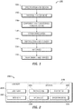
- the exemplary method 100 may include specification and design 104 of the aircraft 200 and material procurement 106.
- component and subassembly manufacturing 108 and system integration 110 of the aircraft 200 takes place.
- the aircraft 200 may go through certification and delivery 112 in order to be placed in service 114.
- routine maintenance and service 116 which may also include modification, reconfiguration, refurbishment, and so on).
- a system integrator may include without limitation any number of aircraft manufacturers and major-system subcontractors; a third party may include without limitation any number of venders, subcontractors, and suppliers; and an operator may be without limitation an airline, leasing company, military entity, service organization, and the like.
- the aircraft 200 produced by the exemplary method 100 may include an airframe 218 with a plurality of systems 220 and an interior 222.
- high-level systems 220 include one or more of a propulsion system 224, an electrical system 226, a hydraulic system 228, and an environmental system 230. Any number of other systems may also be included.
- an aerospace example is shown, the embodiments of the disclosure may be applied to other industries, such as the automotive industry.
- Apparatus and methods embodied herein may be employed during any one or more of the stages of the production and service method 100.
- components or subassemblies corresponding to production process 108 may be fabricated or manufactured in a manner similar to components or subassemblies produced while the aircraft 200 is in service.
- one or more apparatus embodiments, method embodiments, or a combination thereof may be utilized during the production stages 108 and 110, for example, by substantially expediting assembly of or reducing the cost of an aircraft 200.
- apparatus embodiments, method embodiments, or a combination thereof may be utilized while the aircraft 200 is in service, for example and without limitation, to maintenance and service 116.
- Aircraft may be susceptible to lightning or other high energy electromagnetic effects (EME). This problem is further complicated by use of carbon fiber-reinforced plastic (CFRP) structures, which though often conductive, may have less than optimal conductivity for high currents, such as lightning. Sufficient grounding of electrical equipment is also required for normal aircraft operation to protect sensitive equipment and preventing electrical arcing across exposed surfaces. In the event of a current leakage with electrical equipment such as a wing ice protection system (WIPS), the ground path should be sufficient that no electrical arcing can occur in an area where fuel or vapor may be present. This can be challenging if there are moveable joints (such as a bearing) in the potential ground path.
- WIPS wing ice protection system
- FIG 3 is an illustration of a top view of a portion of an aircraft wing 300 showing a plurality of leading edge slats 304 and flaps 306.
- the leading edge slats 304 and flaps 306 are movable external parts that may be exposed to lightning.
- the leading edge slats 304 use wing ice protection systems (WIPS). Because they are movable parts, leading edge slats 304 and flaps 306 are generally installed on the wing 300 using a plurality of bearing assemblies. Because the wing 300 is often used to store fuel, and fuel trucks are frequently near the wings, the leading edge slats 304 and flaps 306 and their bearings can be where no electrical arcing should occur. Thus, they may be good candidates for dielectric bearings that are resistant to electrical arcing.
- WIPS wing ice protection systems
- Flaps 306 are aerodynamic surfaces attached to the trailing edge of the wing main element 302. When deployed, the flaps 306 increase the lift (and drag) of the wing main element 302. The flaps 306 are usually fully extended while landing. Depending on the aircraft type, configuration, and method of takeoff, flaps 306 are often partially extended for take-off to give the aircraft more lift when trying to leave the ground.
- the leading edge slats 304 are aerodynamic surfaces attached to the leading edge of the wing main element 302, which, when deployed, allow the wing main element 302 to operate at a higher angle of attack.
- the leading edge slats 304 are usually deployed while landing, but are usually retracted in normal flight to minimize drag.
- the leading edge slats 304 are partially extended to provide attached flow over the wing main element 302 at high angles of attack.
- the leading edge slats 304 would be retracted to improve the lift-to-drag ratio of the climbout configuration.
- the leading edge slats 304 may be retracted and extended by a drive track (slat track) which is supported inside the wing 300.
- each of the leading edge slats 304 may be coupled to its two respective slat tracks via bearings such as, for example but without limitation, two spherical bearings per slat track as explained below.
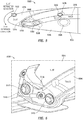
- FIG 4 is an illustration of a perspective view of an exemplary leading edge slat-to-track structure 400 (308 in Figure 3 ) comprising a wing ice protection system (WIPS) 414.
- a leading edge slat 408 is coupled to its two respective slat tracks 410 via two bearings 412 per each of the slat tracks 410 as explained in more detail below in the context of Figures 5 and 6 .
- the leading edge slat 408 is retracted and extended by two drive tracks (slat tracks) 410 which are supported inside the wing 300 ( Figure 3 ) by rollers 508 as shown in Figure 5 below.
- the WIPS 414 may take a significant amount of power and current, so the leading edge of the aircraft may need to accommodate current leakages in the WIPS 414.
- the WIPS 414 may produce a voltage of about 230 volts and about 230 amps current in 3-phase AC.
- FIG. 5 is an illustration of a cross sectional view of a leading edge slat and track 500 showing a WIPS current leakage 512.
- the leading edge slat and track 500 may comprise: a wing 502, a leading edge slat 504, a slat track 506, a plurality of rollers 508, and a plurality of spherical bearings 510.
- the leading edge slat 504 is supported by the rollers 508 located chordwise within 516 the wing 502.
- the rollers 508 may comprise lower front rollers and roller rings rotatably mounted at opposite sides of a rotary actuator pinion gear (not shown).
- the rotary actuator pinion gear engages the slat track 506 and moves the slat track 506 between the slat extended and slat retracted positions.
- the spherical bearings 510 allow alignment variation between two or more parts such as, for example but without limitation, leading edge slat 408 and the two respective slat tracks 410.
- a ground path of the current leakage shall be sufficient so that no electrical arcing can occur where fuel or vapor may be present. This can be challenging if there are moveable joints in the potential ground path.
- Some embodiments of the disclosure as described in more detail below in the context of discussion of Figures 10-16 comprise a conditionally non-conductive material inserted between or coated on parts of the bearing.
- a conditionally non-conductive spherical bearing liner covers side faces of spherical bearings or bushings to electrically isolate the outer ring (outer race) of the spherical bearing from the spherical ball (inner race).
- these embodiments provide dielectric barriers from the spherical ball of the spherical bearing to the outer race of the spherical bearing 510.
- embodiments of the disclosure provide electrical isolation for lower voltages for bonding and grounding purposes, while providing a conductive path for electromagnetic effects purposes such as conducting large voltages of lightning strikes.
- FIG 6 is an illustration of a perspective side view of a portion of leading edge slat and track 500 shown in Figure 5 , including single pin joints where the spherical bearings 510 (dotted lines 412 in Figure 4 and 514 in Figures 5-6 ) may be installed according to an embodiment of the disclosure.
- Sufficient grounding is required to dissipate energy from electrical equipment and lighting.
- a dielectric spherical bearing as described below can isolate current in normal use and be conductive during high-voltage-spike lightning.
- a ground wire 518 may be used to provide a ground path for general electrical current leakages; however, there may still be a need for another ground path across spherical bearings 510.
- FIG 7 is an illustration of a perspective view of an exemplary leading edge slat assembly 700 showing a plurality of slat-to-track attachment assemblies 702 where the spherical bearings may be installed according to an embodiment of the disclosure.
- EME can cause electrical arcing around a bearing, where an arc occurs from the outer ring of the spherical bearing to the inner race or ball, and also from the outer ring (outer race) of the ball to a pin (not shown) connecting the bearing to the slat track 506 ( Figure 5 ).
- Embodiments of the disclosure as described in more detail below comprises a conditionally non-conductive spherical bearing liner (coating) that covers side faces of spherical bearings or bushings to electrically isolate the outer ring of the spherical bearing from the spherical ball.
- these embodiments provide dielectric barriers from the spherical ball of the spherical bearing to the outer ring of the spherical bearing 510, and from other attachment hardware such as pins or bolts.
- the dielectric spherical bearing 510 with polytetrafluoroethylene (PTFE) (Teflon) liners can prevent current from conducting through the slat rack 506, and the current can be managed through a conductive ground path.
- PTFE polytetrafluoroethylene
- Figure 8 is an illustration of an enlarged perspective side view of an exemplary slat-to-track attachment assembly 702 shown in Figure 7 where a spherical bearing 804 and a spherical bearing 806 may be installed according to an embodiment of the disclosure.
- a bearing is a device to allow alignment variation between two or more parts, typically rotation or linear movement. Bearings may be classified broadly according to the motions they allow and according to their principle of operation as well as by the directions of applied loads they can handle. Plain bearings are very widely used, and use surfaces in rubbing contact, often with lubrication.
- a spherical bearing is a bearing that permits angular rotation about a central point in two orthogonal directions (usually within a specified angular limit based on the bearing geometry). Typically these bearings support a rotating shaft in a bore of the inner ring that move rotationally, but can also move at an angle.
- a spherical bearing can be hydrostatic or strictly mechanical.
- a spherical bearing by itself can consist of an outer ring (outer race) and an inner ring (inner race or ball) and a locking feature that makes the inner ring (outer race) captive within the outer ring (outer race) in an axial direction.
- An outer surface of the inner ring and an inner surface of the outer ring are collectively considered the raceway where and they slide against each other, with a lubricant or a maintenance-free PTFE (Teflon) based liner.
- Some spherical bearings incorporate a rolling element such as a race of ball-bearings, allowing lower friction.
- Spherical bearings are used in countless applications, wherever rotational motion should be allowed to change the alignment of its rotation axis.
- a prime example is a tie rod on a vehicle suspension. The mechanics of the suspension allow the axle to move up and down, but the linkages are designed to control that motion in one direction and they should allow motion in the other directions.
- Spherical bearings have been used in aircraft moving surfaces, car suspensions, driveshafts, heavy machinery, sewing machines, and many other applications.
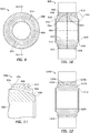
- FIGs 9-11 illustrate a side view, a cross sectional view, and a portion (916 in Figure 10 ) of an exemplary EME isolating dielectric spherical bearing 900 according to an embodiment of the disclosure respectively.
- the dielectric spherical bearing 900 may generally comprise a central opening 902, an inner race 904, an outer race 906, and a conditionally non-conductive bearing liner 914 (coating 914).
- the dielectric spherical bearing 900 may be, without limitation, a concentric bearing, a spherical bearing, a cartridge bearing, and the like.
- a metallic cartridge bearing, and in particular, a spherical plain cartridge bearing is used as an example. Because it is a movable part, the leading edge slat 408 ( Figure 4 ) can be installed on the wing 300 ( Figure 3 ) using a plurality of spherical bearings such as the dielectric spherical bearing 900 as explained below.
- the central opening 902 permits the dielectric spherical bearing 900 to be connected to a coupling structure such as a pin, shaft or a rod while an inner-race outer surface 918 thereof is slidably engaged with the conditionally non-conductive bearing liner 914.
- the inner race 904 may comprise an inner-race outer surface 918 ( Figure 10 ), an inner-race side face 920, and inner-race inner surface 922.
- the inner race 904 may be coupled to a first structure (i.e., slat track 506 in Figure 5 ) via a coupling structure.
- the first structure may be, for example but without limitation, a mounting structure for a slat, a mounting structure for a flap, a mounting structure for a spoiler, and the like.
- the inner race 904 may have, for example but without limitation, a ball shape, a rod shape, a cylinder shape, and the like.
- the inner race 904 may comprise an inner race of, for example but without limitation: a ball bearing, a spherical bearing, a roller bearing, a needle bearing, a bushing, a journal bearing, and the like.
- the outer race 906 may comprise an outer-race inner surface 908, an outer-race side face 910, an outer-race outer surface 924, and swaging grooves 912.
- the outer race 906 may be coupled to a second structure (i.e., leading edge slat 504 in Figure 5 ).
- the second structure maybe, for example but without limitation, a slat, a flap, a spoiler, and the like.
- the outer race 906 may have, for example but without limitation, a ring shape, a cylinder shape, and the like.
- the outer race 906 may comprise an outer race of, for example but without limitation, a ball bearing, a spherical bearing, a roller bearing, a needle bearing, a bushing, a journal bearing, and the like.
- the outer-race inner surface 908 may comprise, for example but without limitation, a concave spherical section, a ring, or the like.
- the swaging grooves 912 are located on the outer-race side face 910.
- a surface finish of the swaging grooves 912 is preferably relatively rough with respect to the inner-race outer surface 918.
- the swaging grooves 912 may have, without limitation, a finish about 32 microinches Ra, while the inner-race outer surface 918, may have, without limitation, a surface finish of 8 microinches Ra.
- conditionally non-conductive bearing liner 914 (coating 914) is wrapped or molded around corners of the outer-race inner surface 908 and the outer-race side face 910 and is extended to the swaging groove 912 to electrically protect the corner of the outer race 906. More specifically, the conditionally non-conductive bearing liner 914 covers the outer-race side face 910 of the dielectric spherical bearing 900 (or bushing) to electrically isolate the outer race 706 from the inner race 904 (spherical ball 904), and from other attachment hardware such as the pins or bolts.
- the dielectric spherical bearing 900 provides dielectric barriers from the spherical ball 904 of the dielectric spherical bearing 900 to the outer race 906 and from other attachment hardware such as the pins or bolts according to an embodiment of the disclosure.
- the conditionally non-conductive bearing liner 914 may be bonded to the outer-race inner surface 908 and the outer-race side face 910.
- the conditionally non-conductive bearing liner 914 may be made from a non-stick material with low friction characteristics such as, for example but without limitation, polytetrafluoroethylene (PTFE) (Teflon), plastic, ceramic, PEEK, Nylon, Mylar, Acrylic, Sealant, Polysulfide, silicon, Bonded isolation, Phenolic, a mechanically fastened isolating seal, a conductive material coated by a conditionally non-conductive material, and the like. Thickness of the conditionally non-conductive bearing liner 914 may be, for example but without limitation, about 0.010 inches to about 0.020 inches.
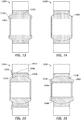
- Figures 12-16 are illustrations of various dielectric spherical bearings. Each of the bearings shown in Figures 12-16 has a structure that is similar to the dielectric spherical bearing 900 shown in Figures 9-11 . Therefore common features, functions, and elements may not be redundantly described here.
- Figure 12 is an illustration of a cross sectional view of an exemplary dielectric spherical bearing 1200 showing conditionally non-conductive inserts 1202 according to an embodiment of the disclosure.
- the conditionally non-conductive inserts 1202 may be coupled to the inner race 1204. the outer race 12 and at least one of the inner-race side face 1212 and the outer-race side face 1210.
- the conditionally non-conductive inserts 1202 may be inserted from the sides of the dielectric spherical bearing 1200 in between the inner race 1204 and the outer race 1206.
- a plurality of holes or areas 1214 where current flow over a voltage threshold can occur in the event of high energy strike may be included in the conditionally non-conductive inserts 1202.
- the holes 1214 allow current flow if the voltage across the inner race 1204 and the outer race 1206 exceeds the voltage threshold.
- the voltage threshold may be, for example but without limitation, about 300V.
- the conditionally non-conductive inserts 1202 may be made, for example but without limitation, from a conductive material, such as, metal coated by a conditionally non-conductive finish.
- the metal may be, for example but without limitation, copper beryllium copper alloy or a precipitation hardened stainless steel, and the like.
- the conditionally non-conductive finish may be without limitation, PTFE, ceramic, and the like.
- Figure 13 is an illustration of a cross sectional view of an exemplary dielectric spherical bearing 1300 showing a conditionally non-conductive coating 1302 on the inner race 1304.
- the conditionally non-conductive coating 1302 may be extended to an inner-race side face 1312.
- the conditionally non-conductive coating 1302 may be formed from, for example but without limitation, PTFE, Teflon, ceramic, plastic, PEEK, and the like.
- Figure 14 is an illustration of a cross sectional view of an exemplary dielectric spherical bearing 1400 showing a conditionally non-conductive inner race 1402.
- the conditionally non-conductive inner race 1402 may be formed from, for example but without limitation, plastics, ceramic, peek, and the like.
- Figure 15 is an illustration of a cross sectional view of an exemplary dielectric spherical bearing 1500 showing a conditionally non-conductive coating/insert 1502 on an outer surface 1504 and side face 1506 of an outer race 1508, and extended to a portion of track (second) structure 1510.
- Figure 16 is an illustration of a cross sectional view of an exemplary dielectric spherical bearing 1600 showing a conditionally non-conductive coating/insert 1602 on an inner surface 1604 and side face 1606 of an inner race 1608.
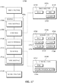
- Figure 17 is an illustration of a functional block diagram 1700 showing a conditionally non-conductive bearing 1704 (bearing 1704).
- the bearing 1704 is a generalization of the bearings shown in Figures 10 and 12-16 .
- the functional block diagram 1700 may have functions, material, and structures that are similar to the bearings shown in Figures 4-17 . Therefore common features, functions, and elements may not be redundantly described here.
- the bearing 1704 allows conditional conductivity between a first structure 1702 and a second structure 1716.
- the bearing 1704 comprises a first interface 1706, an inner race 1708, a second interface 1710, an outer race 1712, and a third interface 1714.
- the bearing 1704 may comprise bearing type 1726.
- Each of the embodiments and arrangements shown in Figures 10 and 12-16 can be applied to the bearing type 1726, such as but without limitation, ball bearings 1728, needle bearings 1730, spherical bearings 1732 (which may be lubricated spherical bearings), bushings 1734, roller bearings 1736, journal bearings 1738, and the like.
- the first interface 1706 comprises an interface between the first structure 1702 and the inner race 1708.
- the bearing shown in Figure 16 provides conditional isolation at the first interface 1706 (1602 in Figure 16 ).
- the inner race 1708 may have an inner race type 1724 with a shape of, for example but without limitation, a rod 1718, a ball 1720, a cylinder 1722, and the like.
- the arrangement shown in Figure 14 provides conditional isolation at the inner race 1708 (1402 in Figure 14 ).
- the second interface 1710 comprises an interface between the inner race 1708 and the outer race 1712.
- the bearings shown in Figures 10, 12 , and 13 provide conditional isolation at the second interface 1710 (914 in Figure 10 , 1202 in Figure 12 , and 1302 in Figure 13 respectively).
- the outer race 1712 may comprise outer race type 1740, such as but without limitation, a ring 1742, a concave spherical section 1744, or the like.
- the third interface 1714 comprises an interface between the outer race 1712 and the second structure 1716.
- the bearing shown in Figure 15 provides conditional isolation at the third interface 1714 (1502 in Figure 15 ).
- the first interface 1706, the second interface 1710, and the third interface 1714 may be made, for example but without limitation, from any of the material discussed in the context of discussion of Figures 9-11 above.
- FIG 18 is an illustration of a flowchart showing an exemplary process 1800 for providing electrical isolation for a conditionally non-conductive bearing according to an embodiment of the disclosure.
- the various tasks performed in connection with process 1800 may be performed by software, hardware, firmware, or any combination thereof.
- the following description of process 1800 may refer to elements mentioned above in connection with Figures 1-2 and 7-17 .
- portions of process 1800 may be performed by different elements of conditionally non-conductive bearings such as the bearings 900-1600 and/or the bearing 1704.
- Process 1800 may have functions, material, and structures that are similar to the embodiments and arrangements shown in Figures 4-17 . Therefore common features, functions, and elements may not be redundantly described here.
- Process 1800 may begin by providing an inner race (i.e., 1708 in Figure 17 ) coupled to a first structure (task 1802).
- Process 1800 may continue by providing an outer race (i.e., 1712 in Figure 17 ) coupled to a second structure (task 1804).
- Process 1800 may continue by providing an isolative means (i.e., the first interface 1706, the second interface 1710, and/or the third interface 1714 in Figure 17 ) conditionally isolating the first structure from the second structure (task 1806).
- an isolative means i.e., the first interface 1706, the second interface 1710, and/or the third interface 1714 in Figure 17
- conditionally isolating the first structure from the second structure (task 1806).
- a conditionally non-conductive coating may be placed on the outer-race (or ring) inner surface and the outer-race side face of the conditionally non-conductive bearing.
- the conditionally non-conductive coating may be added to the bearing by, for example but without limitation, molding the conditionally non-conductive coating, or wrapping and bonding a fabric to the various surfaces of the bearing and support structures.
- the coating can be coated by, for example but without limitation, a wrapped fabric, a three part bonded liner, a molded or machined homogeneous liner, and the like.
- the side face liner material can be extended beyond the initial geometry for lining the bore, where the extra material would be woven to allow the material to turn about 90 degrees around an edge of the outer race, and bond.
- a washer made of a molded or fabric base can be bonded to the outer-race side face (i.e., 910 in Figure 10 of the dielectric spherical bearing 900), where the side face conditionally non-conductive liner and a liner in the bearing can be integrated by bonding with a resin.
- a liner is molded between the spherical ball and the outer race, and a parting agent is used to allow the spherical ball to move after the liner has set.
- the side face could be molded using a molding washer with an internal relief on each side face that would allow the resin to flow beyond current limits, up and around each side face. Once the liner has set up, the molding washer could be removed. A machining step may be incorporated to bring the liner to finished size.
- Process 1800 may then continue by determining if an electrical voltage is greater than a voltage threshold (inquiry task 1808).
- Process 1800 electrically isolates the first structure from the second structure (task 1810), if the electrical voltage (first electrical voltage) is less than the voltage threshold. However, process 1800 electrically couples the first structure to the second structure (task 1812), if the electrical voltage (second electrical voltage) is greater than the voltage threshold, thereby allowing electrical conductivity.
- the voltage threshold may be, for example but without limitation, about 300 volts.
- process 1800 provides electrical isolation between a slat and a slat track for lower voltages (first electrical voltage) for bonding and grounding purposes, while providing a conductive path for electromagnetic effects purposes such as conducting large voltages (second electrical voltage) of lightning strikes.
- conditionally non-conductive bearings such as the dielectric spherical bearing isolates current in normal use and is conductive during high-voltage-spike lightning. Therefore, in the event of a current leakage with electrical equipment, or lighting a sufficient ground path is provided to prevent electrical arcing to occur where fuel or vapor may be present.
- the conditionally non-conductive bearings provide sufficient grounding to dissipate the energy without damaging any sensitive electrical equipment that may be in the area.
Landscapes
- Engineering & Computer Science (AREA)
- General Engineering & Computer Science (AREA)
- Mechanical Engineering (AREA)
- Aviation & Aerospace Engineering (AREA)
- Rolling Contact Bearings (AREA)
- Motor Or Generator Frames (AREA)
Claims (8)
- Lager (900) zur Verwendung in einem System zum Isolieren von elektrischem Strom in einer Flugzeugstruktur, wobei das Lager aufweist:einen Innenring (904), der eine Innenring-Innenfläche (922), eine Innenring-Außenfläche (918) und eine Innenring-Seitenfläche (920) aufweist, wobei der Innenring zum Koppeln an eine erste Struktur dient;einen Außenring (906), der eine Außenring-Innenfläche (908), eine Außenring-Außenfläche (924) und eine Außenring-Seitenfläche (910) aufweist, wobei der Außenring an den Innenring gekoppelt ist und zum Koppeln an eine zweite Struktur dient; undein bedingt nicht leitendes Mittel (914), das ein bedingt nicht leitendes Material aufweist, auf der Außenring-Innenfläche und der Außenring-Seitenfläche, wobei das bedingt nicht leitende Mittel zum bedingten elektrischen Isolieren der ersten Struktur von der zweiten Struktur dient;wobei das bedingt nicht leitende Mittel betreibbar ist, um die erste Struktur von der zweiten Struktur elektrisch zu isolieren, wenn eine erste elektrische Spannung niedriger ist als eine Spannungsschwelle, und die erste Struktur elektrisch an die zweite Struktur zu koppeln, wenn eine zweite elektrische Spannung höher ist als die Spannungsschwelle.
- Lager (900) nach Anspruch 1, wobei der Innenring (904) einen Innenring aus zumindest einem aus der Gruppe aufweist, die besteht aus: einem Kugellager, einem Kalottenlager, einem Rollenlager, einem Nadellager, einer Lagerbuchse und einem Lagerzapfen; und/oder der Außenring (906) einen Außenring aus zumindest einem aus der Gruppe aufweist, die besteht aus: einem Kugellager, einem Kalottenlager, einem Rollenlager, einem Nadellager, einer Lagerbuchse und einem Lagerzapfen.
- Lager (900) nach Anspruch 1, wobei das bedingt nicht leitende Mittel zumindest eines aus der Gruppe aufweist, die besteht aus: PTFE, Teflon, Kunststoff, Keramik, PEEK, Dichtmasse, Polysulfid, Silikon, Acryl, Nylon, Mylar, Phenolharz und einem leitfähigen Material, das mit einem bedingt nicht leitenden Material beschichtet ist.
- Lager (1200) zur Verwendung in einem System zum Isolieren von elektrischem Strom in einer Flugzeugstruktur, wobei das Lager aufweist:einen Innenring (1204), der eine Innenring-Innenfläche, eine Innenring-Außenfläche und eine Innenring-Seitenfläche (1212) aufweist, wobei der Innenring zum Koppeln an eine erste Struktur dient;einen Außenring (1206), der eine Außenring-Innenfläche, eine Außenring-Außenfläche und eine Außenring-Seitenfläche (1210) aufweist, wobei der Außenring an den Innenring gekoppelt ist und zum Koppeln an eine zweite Struktur dient; undein bedingt nicht leitendes Mittel, das einen Einsatz (1202) aufweist, wobei der Einsatz (1202) an den Innenring, den Außenring und zumindest eines aus der Gruppe gekoppelt ist, die besteht aus: der Innenring-Seitenfläche und der Außenring-Seitenfläche, und wobei der Einsatz (1202) dazu dient, die erste Struktur bedingt von der zweiten Struktur elektrisch zu isolieren, wobei der Einsatz zumindest ein Loch (1214) aufweist, das zum Leiten von Strom betreibbar ist, wenn eine elektrische Spannung höher ist als eine Spannungsschwelle;wobei der Einsatz betreibbar ist, um die erste Struktur von der zweiten Struktur elektrisch zu isolieren, wenn eine erste elektrische Spannung niedriger ist als eine Spannungsschwelle, und die erste Struktur elektrisch an die zweite Struktur zu koppeln, wenn eine zweite elektrische Spannung höher ist als die Spannungsschwelle.
- Verwendung eines Lagers (1400) in einem elektrischen Stromisolationssystem in einer Flugzeugstruktur, wobei das Lager aufweist:einen Innenring (1402) zum Koppeln an eine erste Struktur, wobei der Innenring aus einem bedingt nicht leitenden Material gebildet ist; undeinen Außenring, der an den Innenring gekoppelt ist und zum Koppeln an eine zweite Struktur dient;wobei der bedingt nicht leitende Innenring betreibbar ist, um die erste Struktur von der zweiten Struktur elektrisch zu isolieren, wenn eine erste elektrische Spannung niedriger ist als eine Spannungsschwelle, und die erste Struktur elektrisch an die zweite Struktur zu koppeln, wenn eine zweite elektrische Spannung höher ist als die Spannungsschwelle.
- Verfahren (1800) zum Bereitstellen einer bedingten elektrischen Isolierung für ein Lager (900, 1200) wobei das Verfahren aufweist:Bereitstellen (1802) eines Innenringes (904), der eine Innenring-Innenfläche (922), eine Innenring-Außenfläche (918) und eine Innenring-Seitenfläche (920) aufweist, wobei der Innenring zum Koppeln an eine erste Struktur dient;Bereitstellen (1804) eines Außenringes (906), der eine Außenring-Innenfläche (908), eine Außenring-Außenfläche (924) und eine Außenring-Seitenfläche (910) aufweist, wobei der Außenring zum Koppeln an eine zweite Struktur dient; undBereitstellen (1806) eines isolativen Mittels, das ein bedingt nicht leitendes Material (914) aufweist, auf der Außenring-Innenfläche und der Außenringseite, wobei das isolative Mittel zum bedingten elektrischen Isolieren der ersten Struktur von der zweiten Struktur dient;wobei das Verfahren mithilfe des isolativen Mittels ferner aufweist:elektrisches Isolieren (1810) der ersten Struktur von der zweiten Struktur, wenn eine erste elektrische Spannung niedriger ist als eine Spannungsschwelle; undelektrisches Koppeln (1812) der ersten Struktur an die zweite Struktur, wenn eine zweite elektrische Spannung höher ist als die Spannungsschwelle.
- Verfahren (1800) nach Anspruch 6, wobei der Innenring (904) einen Innenring aus zumindest einem aus der Gruppe aufweist, die besteht aus: einem Kugellager, einem Kalottenlager, einem Rollenlager, einem Nadellager, einer Lagerbuchse und einem Lagerzapfen; und/oder der Außenring (906) einen Außenring aus zumindest einem aus der Gruppe aufweist, die besteht aus: einem Kugellager, einem Kalottenlager, einem Rollenlager, einem Nadellager, einer Lagerbuchse und einem Lagerzapfen.
- Verfahren nach Anspruch 6, wobei das bedingt nicht leitende Material (914) zumindest eines aus der Gruppe aufweist, die besteht aus: PTFE, Teflon, Kunststoff, Keramik, PEEK, Dichtmasse, Polysulfid, Silikon, Acryl, Nylon, Mylar, Phenolharz, einer mechanisch befestigten isolierenden Dichtung und einem leitfähigen Material, das mit einem bedingt nicht leitenden Material beschichtet ist.
Applications Claiming Priority (2)
| Application Number | Priority Date | Filing Date | Title |
|---|---|---|---|
| US12/542,307 US8393791B2 (en) | 2009-08-17 | 2009-08-17 | Bearing side face electrical isolation |
| PCT/US2010/043553 WO2011022179A2 (en) | 2009-08-17 | 2010-07-28 | Bearing side face electrical isolation |
Publications (2)
| Publication Number | Publication Date |
|---|---|
| EP2467296A2 EP2467296A2 (de) | 2012-06-27 |
| EP2467296B1 true EP2467296B1 (de) | 2019-02-13 |
Family
ID=43588653
Family Applications (1)
| Application Number | Title | Priority Date | Filing Date |
|---|---|---|---|
| EP10742634.8A Active EP2467296B1 (de) | 2009-08-17 | 2010-07-28 | Laterale elektrische isolation für ein lager |
Country Status (4)
| Country | Link |
|---|---|
| US (1) | US8393791B2 (de) |
| EP (1) | EP2467296B1 (de) |
| ES (1) | ES2726038T3 (de) |
| WO (1) | WO2011022179A2 (de) |
Cited By (1)
| Publication number | Priority date | Publication date | Assignee | Title |
|---|---|---|---|---|
| EP3751161B1 (de) * | 2019-06-14 | 2023-09-27 | Safran Landing Systems UK Ltd | Selbstschmierende buchsenanordnung |
Families Citing this family (21)
| Publication number | Priority date | Publication date | Assignee | Title |
|---|---|---|---|---|
| US10023302B2 (en) | 2007-12-06 | 2018-07-17 | Roller Bearing Company Of America, Inc. | Actuation system for a lift assisting device and lined track rollers used therein |
| GB0810460D0 (en) * | 2008-06-09 | 2008-07-09 | Airbus Uk Ltd | Support assembly |
| US9261132B2 (en) | 2009-04-24 | 2016-02-16 | Roller Bearing Company Of America, Inc. | Low friction bearing assembly and link apparatus |
| DE102009056349A1 (de) * | 2009-11-30 | 2011-06-01 | Schaeffler Technologies Gmbh & Co. Kg | Wälzlager |
| WO2013090758A1 (en) | 2011-12-14 | 2013-06-20 | Roller Bearing Company Of America, Inc. | Slotted bearings with wear-resistant treatments for gearbox mounting in a geared turbofan engine |
| WO2014021958A1 (en) | 2012-04-30 | 2014-02-06 | Roller Bearing Company Of America, Inc. | Hybrid bearing assembly with rolling elements and plain bearing |
| US9914523B2 (en) * | 2012-10-30 | 2018-03-13 | The Boeing Company | Wing hinge assembly including hinged torque boxes |
| EP3006751B1 (de) * | 2014-09-17 | 2018-11-07 | Roller Bearing Company of America, Inc. | System zur elektrischen isolierung von strom in einem lager zur verwendung in einer flugzeugstruktur |
| US10457412B2 (en) * | 2016-09-16 | 2019-10-29 | Rosemount Aerospace Inc. | Electrical isolation of angle of attack vane bearings |
| FR3067073B1 (fr) * | 2017-06-06 | 2019-07-05 | SKF Aerospace France S.A.S | Connecteur avec rotule integree |
| US11066148B2 (en) * | 2018-08-06 | 2021-07-20 | The Boeing Company | Folding wing hinge, aircraft and method therefor |
| US10634710B1 (en) * | 2018-10-31 | 2020-04-28 | Wisk Aero Llc | Ground network monitoring system |
| US11130563B2 (en) * | 2018-11-07 | 2021-09-28 | The Boeing Company | Monolithic outboard gear beam support fitting |
| US11608156B2 (en) * | 2019-03-26 | 2023-03-21 | Yaborä Indústria Aeronáutica S.A. | Lateral roller assemblies for wing leading edge slat tracks |
| US11560923B2 (en) | 2019-06-07 | 2023-01-24 | Schaublin Sa | Self-lubricated electrically conductive bushing |
| CN113978701B (zh) * | 2021-12-17 | 2024-04-02 | 江西洪都航空工业集团有限责任公司 | 一种动轴式全动舵面安装机构 |
| US11932378B2 (en) * | 2022-02-09 | 2024-03-19 | The Boeing Company | Actuated assemblies, kits, aircraft, and methods of utilizing the same |
| US12227300B2 (en) | 2022-10-06 | 2025-02-18 | Archer Aviation Inc. | Systems and methods for oil maintenance in gearboxes for eVTOL aircraft |
| US12312091B2 (en) | 2022-10-06 | 2025-05-27 | Archer Aviation Inc. | Systems and methods for improved gearboxes for evtol aircraft |
| US11787551B1 (en) | 2022-10-06 | 2023-10-17 | Archer Aviation, Inc. | Vertical takeoff and landing aircraft electric engine configuration |
| EP4477531A1 (de) | 2023-06-14 | 2024-12-18 | Airbus Operations GmbH | Flügel für ein flugzeug |
Citations (2)
| Publication number | Priority date | Publication date | Assignee | Title |
|---|---|---|---|---|
| DE2234984A1 (de) * | 1972-07-17 | 1974-02-07 | Star Kugelhalter Gmbh Dt | Waelzlager |
| US3993369A (en) * | 1975-04-23 | 1976-11-23 | Heim Universal Corporation | Bearing assembly with deformable inner member |
Family Cites Families (12)
| Publication number | Priority date | Publication date | Assignee | Title |
|---|---|---|---|---|
| DE8029066U1 (de) | 1981-02-26 | Siemens Ag, 1000 Berlin Und 8000 Muenchen | Isoliertes Wälzlager | |
| US2370173A (en) * | 1941-08-25 | 1945-02-27 | Elizabeth B Dickson | Antifriction bearing |
| US3672734A (en) * | 1970-07-23 | 1972-06-27 | Bando Kiko Co | Bearing adaptor |
| US4080015A (en) | 1976-08-02 | 1978-03-21 | Lear Siegler, Inc. | Bearing and method for manufacturing same |
| EP0301130B1 (de) * | 1987-07-25 | 1992-03-25 | Firma Carl Freudenberg | Wälzlagerung |
| JPH03103615A (ja) * | 1989-09-12 | 1991-04-30 | Railway Technical Res Inst | 電気絶縁軸受 |
| NL9100036A (nl) | 1991-01-11 | 1992-08-03 | Pieter Jan Hendrik Hoeymakers | Inrichting voor het reinigen van oppervlakken. |
| DE4100587A1 (de) | 1991-01-11 | 1992-07-16 | Skf Gmbh | Elektrisch isoliertes waelzlager |
| US5735615A (en) * | 1996-10-04 | 1998-04-07 | Reliance Electric Industrial Company | Insulation arrangement for electrical machine shaft bearing |
| JP2005133876A (ja) * | 2003-10-31 | 2005-05-26 | Ntn Corp | 電食防止型転がり軸受 |
| DE102004035212A1 (de) | 2004-07-21 | 2006-02-16 | Ina-Schaeffler Kg | Wälzlager |
| US20080040886A1 (en) | 2006-01-26 | 2008-02-21 | Roller Bearing Company Of America, Inc. | Bearing and hinge mechanism |
-
2009
- 2009-08-17 US US12/542,307 patent/US8393791B2/en active Active
-
2010
- 2010-07-28 WO PCT/US2010/043553 patent/WO2011022179A2/en not_active Ceased
- 2010-07-28 ES ES10742634T patent/ES2726038T3/es active Active
- 2010-07-28 EP EP10742634.8A patent/EP2467296B1/de active Active
Patent Citations (2)
| Publication number | Priority date | Publication date | Assignee | Title |
|---|---|---|---|---|
| DE2234984A1 (de) * | 1972-07-17 | 1974-02-07 | Star Kugelhalter Gmbh Dt | Waelzlager |
| US3993369A (en) * | 1975-04-23 | 1976-11-23 | Heim Universal Corporation | Bearing assembly with deformable inner member |
Cited By (1)
| Publication number | Priority date | Publication date | Assignee | Title |
|---|---|---|---|---|
| EP3751161B1 (de) * | 2019-06-14 | 2023-09-27 | Safran Landing Systems UK Ltd | Selbstschmierende buchsenanordnung |
Also Published As
| Publication number | Publication date |
|---|---|
| US8393791B2 (en) | 2013-03-12 |
| WO2011022179A3 (en) | 2011-12-22 |
| US20110038576A1 (en) | 2011-02-17 |
| WO2011022179A2 (en) | 2011-02-24 |
| ES2726038T3 (es) | 2019-10-01 |
| EP2467296A2 (de) | 2012-06-27 |
Similar Documents
| Publication | Publication Date | Title |
|---|---|---|
| EP2467296B1 (de) | Laterale elektrische isolation für ein lager | |
| US10960967B2 (en) | Wing and fastening system for a wing | |
| US20170284449A1 (en) | Conformal clearance fit fastener, fastener system, and method for composite structures | |
| US20100000991A1 (en) | Thermally activated variable stiffness composites for aircraft seals | |
| EP3719375B1 (de) | Verbundverbinder und verfahren zur herstellung davon | |
| EP2540625B1 (de) | Elektrisch leitende Struktur | |
| WO2015006427A1 (en) | Plated polymer aviation components | |
| JP6132599B2 (ja) | テールスキッドアセンブリの展開位置を変更するための方法および装置 | |
| EP2352670B1 (de) | Fahrwerkladetür mit rollenschlitzmechanismus | |
| EP3173639B1 (de) | Selbstschmierendes drucklager für einen klappbaren flugzeugflügel | |
| EP3006751B1 (de) | System zur elektrischen isolierung von strom in einem lager zur verwendung in einer flugzeugstruktur | |
| CA3046912C (en) | Manufacture and process for inhibiting wear in a latch system | |
| EP3296365B1 (de) | Verfahren zur förderung der elektrischen leitung zwischen metallkomponenten und verbundmaterialien | |
| US11560923B2 (en) | Self-lubricated electrically conductive bushing | |
| CN104832578A (zh) | 运动阻尼系统及包括该系统的方法 | |
| Alarifi et al. | Mitigation of lightning strikes on composite aircraft via micro and nanoscale materials | |
| US10046528B2 (en) | Composite layers with exposed reinforcement | |
| RU2556266C2 (ru) | Узел подшипника (варианты) и способ установки подшипника в корпусе (варианты) | |
| US8998124B2 (en) | Aircraft with electrically conductive nanocoating | |
| EP3299297B1 (de) | Drehflügelflugzeug mit strukturanordnung mit einer elektrisch leitenden verbindung | |
| US20260048565A1 (en) | Thermally protected polymer composites and associated methods | |
| AU2012202685B8 (en) | Electrically conductive structure |
Legal Events
| Date | Code | Title | Description |
|---|---|---|---|
| PUAI | Public reference made under article 153(3) epc to a published international application that has entered the european phase |
Free format text: ORIGINAL CODE: 0009012 |
|
| 17P | Request for examination filed |
Effective date: 20120316 |
|
| AK | Designated contracting states |
Kind code of ref document: A2 Designated state(s): AL AT BE BG CH CY CZ DE DK EE ES FI FR GB GR HR HU IE IS IT LI LT LU LV MC MK MT NL NO PL PT RO SE SI SK SM TR |
|
| DAX | Request for extension of the european patent (deleted) | ||
| 17Q | First examination report despatched |
Effective date: 20121205 |
|
| GRAP | Despatch of communication of intention to grant a patent |
Free format text: ORIGINAL CODE: EPIDOSNIGR1 |
|
| INTG | Intention to grant announced |
Effective date: 20160229 |
|
| GRAJ | Information related to disapproval of communication of intention to grant by the applicant or resumption of examination proceedings by the epo deleted |
Free format text: ORIGINAL CODE: EPIDOSDIGR1 |
|
| INTC | Intention to grant announced (deleted) | ||
| GRAS | Grant fee paid |
Free format text: ORIGINAL CODE: EPIDOSNIGR3 |
|
| STAA | Information on the status of an ep patent application or granted ep patent |
Free format text: STATUS: GRANT OF PATENT IS INTENDED |
|
| GRAP | Despatch of communication of intention to grant a patent |
Free format text: ORIGINAL CODE: EPIDOSNIGR1 |
|
| INTG | Intention to grant announced |
Effective date: 20170906 |
|
| GRAJ | Information related to disapproval of communication of intention to grant by the applicant or resumption of examination proceedings by the epo deleted |
Free format text: ORIGINAL CODE: EPIDOSDIGR1 |
|
| GRAL | Information related to payment of fee for publishing/printing deleted |
Free format text: ORIGINAL CODE: EPIDOSDIGR3 |
|
| STAA | Information on the status of an ep patent application or granted ep patent |
Free format text: STATUS: EXAMINATION IS IN PROGRESS |
|
| INTC | Intention to grant announced (deleted) | ||
| GRAP | Despatch of communication of intention to grant a patent |
Free format text: ORIGINAL CODE: EPIDOSNIGR1 |
|
| STAA | Information on the status of an ep patent application or granted ep patent |
Free format text: STATUS: GRANT OF PATENT IS INTENDED |
|
| INTG | Intention to grant announced |
Effective date: 20180220 |
|
| GRAJ | Information related to disapproval of communication of intention to grant by the applicant or resumption of examination proceedings by the epo deleted |
Free format text: ORIGINAL CODE: EPIDOSDIGR1 |
|
| GRAL | Information related to payment of fee for publishing/printing deleted |
Free format text: ORIGINAL CODE: EPIDOSDIGR3 |
|
| STAA | Information on the status of an ep patent application or granted ep patent |
Free format text: STATUS: EXAMINATION IS IN PROGRESS |
|
| INTC | Intention to grant announced (deleted) | ||
| GRAR | Information related to intention to grant a patent recorded |
Free format text: ORIGINAL CODE: EPIDOSNIGR71 |
|
| STAA | Information on the status of an ep patent application or granted ep patent |
Free format text: STATUS: GRANT OF PATENT IS INTENDED |
|
| GRAA | (expected) grant |
Free format text: ORIGINAL CODE: 0009210 |
|
| STAA | Information on the status of an ep patent application or granted ep patent |
Free format text: STATUS: THE PATENT HAS BEEN GRANTED |
|
| INTG | Intention to grant announced |
Effective date: 20190103 |
|
| AK | Designated contracting states |
Kind code of ref document: B1 Designated state(s): AL AT BE BG CH CY CZ DE DK EE ES FI FR GB GR HR HU IE IS IT LI LT LU LV MC MK MT NL NO PL PT RO SE SI SK SM TR |
|
| REG | Reference to a national code |
Ref country code: GB Ref legal event code: FG4D |
|
| REG | Reference to a national code |
Ref country code: CH Ref legal event code: EP Ref country code: AT Ref legal event code: REF Ref document number: 1096036 Country of ref document: AT Kind code of ref document: T Effective date: 20190215 |
|
| REG | Reference to a national code |
Ref country code: IE Ref legal event code: FG4D |
|
| REG | Reference to a national code |
Ref country code: DE Ref legal event code: R096 Ref document number: 602010056957 Country of ref document: DE |
|
| REG | Reference to a national code |
Ref country code: LT Ref legal event code: MG4D |
|
| REG | Reference to a national code |
Ref country code: NL Ref legal event code: MP Effective date: 20190213 |
|
| PG25 | Lapsed in a contracting state [announced via postgrant information from national office to epo] |
Ref country code: PT Free format text: LAPSE BECAUSE OF FAILURE TO SUBMIT A TRANSLATION OF THE DESCRIPTION OR TO PAY THE FEE WITHIN THE PRESCRIBED TIME-LIMIT Effective date: 20190613 Ref country code: LT Free format text: LAPSE BECAUSE OF FAILURE TO SUBMIT A TRANSLATION OF THE DESCRIPTION OR TO PAY THE FEE WITHIN THE PRESCRIBED TIME-LIMIT Effective date: 20190213 Ref country code: NL Free format text: LAPSE BECAUSE OF FAILURE TO SUBMIT A TRANSLATION OF THE DESCRIPTION OR TO PAY THE FEE WITHIN THE PRESCRIBED TIME-LIMIT Effective date: 20190213 Ref country code: SE Free format text: LAPSE BECAUSE OF FAILURE TO SUBMIT A TRANSLATION OF THE DESCRIPTION OR TO PAY THE FEE WITHIN THE PRESCRIBED TIME-LIMIT Effective date: 20190213 Ref country code: NO Free format text: LAPSE BECAUSE OF FAILURE TO SUBMIT A TRANSLATION OF THE DESCRIPTION OR TO PAY THE FEE WITHIN THE PRESCRIBED TIME-LIMIT Effective date: 20190513 Ref country code: FI Free format text: LAPSE BECAUSE OF FAILURE TO SUBMIT A TRANSLATION OF THE DESCRIPTION OR TO PAY THE FEE WITHIN THE PRESCRIBED TIME-LIMIT Effective date: 20190213 |
|
| PG25 | Lapsed in a contracting state [announced via postgrant information from national office to epo] |
Ref country code: GR Free format text: LAPSE BECAUSE OF FAILURE TO SUBMIT A TRANSLATION OF THE DESCRIPTION OR TO PAY THE FEE WITHIN THE PRESCRIBED TIME-LIMIT Effective date: 20190514 Ref country code: BG Free format text: LAPSE BECAUSE OF FAILURE TO SUBMIT A TRANSLATION OF THE DESCRIPTION OR TO PAY THE FEE WITHIN THE PRESCRIBED TIME-LIMIT Effective date: 20190513 Ref country code: IS Free format text: LAPSE BECAUSE OF FAILURE TO SUBMIT A TRANSLATION OF THE DESCRIPTION OR TO PAY THE FEE WITHIN THE PRESCRIBED TIME-LIMIT Effective date: 20190613 Ref country code: LV Free format text: LAPSE BECAUSE OF FAILURE TO SUBMIT A TRANSLATION OF THE DESCRIPTION OR TO PAY THE FEE WITHIN THE PRESCRIBED TIME-LIMIT Effective date: 20190213 Ref country code: HR Free format text: LAPSE BECAUSE OF FAILURE TO SUBMIT A TRANSLATION OF THE DESCRIPTION OR TO PAY THE FEE WITHIN THE PRESCRIBED TIME-LIMIT Effective date: 20190213 |
|
| REG | Reference to a national code |
Ref country code: AT Ref legal event code: MK05 Ref document number: 1096036 Country of ref document: AT Kind code of ref document: T Effective date: 20190213 |
|
| REG | Reference to a national code |
Ref country code: ES Ref legal event code: FG2A Ref document number: 2726038 Country of ref document: ES Kind code of ref document: T3 Effective date: 20191001 |
|
| PG25 | Lapsed in a contracting state [announced via postgrant information from national office to epo] |
Ref country code: AL Free format text: LAPSE BECAUSE OF FAILURE TO SUBMIT A TRANSLATION OF THE DESCRIPTION OR TO PAY THE FEE WITHIN THE PRESCRIBED TIME-LIMIT Effective date: 20190213 Ref country code: SK Free format text: LAPSE BECAUSE OF FAILURE TO SUBMIT A TRANSLATION OF THE DESCRIPTION OR TO PAY THE FEE WITHIN THE PRESCRIBED TIME-LIMIT Effective date: 20190213 Ref country code: DK Free format text: LAPSE BECAUSE OF FAILURE TO SUBMIT A TRANSLATION OF THE DESCRIPTION OR TO PAY THE FEE WITHIN THE PRESCRIBED TIME-LIMIT Effective date: 20190213 Ref country code: CZ Free format text: LAPSE BECAUSE OF FAILURE TO SUBMIT A TRANSLATION OF THE DESCRIPTION OR TO PAY THE FEE WITHIN THE PRESCRIBED TIME-LIMIT Effective date: 20190213 Ref country code: EE Free format text: LAPSE BECAUSE OF FAILURE TO SUBMIT A TRANSLATION OF THE DESCRIPTION OR TO PAY THE FEE WITHIN THE PRESCRIBED TIME-LIMIT Effective date: 20190213 Ref country code: RO Free format text: LAPSE BECAUSE OF FAILURE TO SUBMIT A TRANSLATION OF THE DESCRIPTION OR TO PAY THE FEE WITHIN THE PRESCRIBED TIME-LIMIT Effective date: 20190213 |
|
| REG | Reference to a national code |
Ref country code: DE Ref legal event code: R097 Ref document number: 602010056957 Country of ref document: DE |
|
| PG25 | Lapsed in a contracting state [announced via postgrant information from national office to epo] |
Ref country code: SM Free format text: LAPSE BECAUSE OF FAILURE TO SUBMIT A TRANSLATION OF THE DESCRIPTION OR TO PAY THE FEE WITHIN THE PRESCRIBED TIME-LIMIT Effective date: 20190213 Ref country code: PL Free format text: LAPSE BECAUSE OF FAILURE TO SUBMIT A TRANSLATION OF THE DESCRIPTION OR TO PAY THE FEE WITHIN THE PRESCRIBED TIME-LIMIT Effective date: 20190213 |
|
| PLBE | No opposition filed within time limit |
Free format text: ORIGINAL CODE: 0009261 |
|
| STAA | Information on the status of an ep patent application or granted ep patent |
Free format text: STATUS: NO OPPOSITION FILED WITHIN TIME LIMIT |
|
| PG25 | Lapsed in a contracting state [announced via postgrant information from national office to epo] |
Ref country code: AT Free format text: LAPSE BECAUSE OF FAILURE TO SUBMIT A TRANSLATION OF THE DESCRIPTION OR TO PAY THE FEE WITHIN THE PRESCRIBED TIME-LIMIT Effective date: 20190213 |
|
| 26N | No opposition filed |
Effective date: 20191114 |
|
| PG25 | Lapsed in a contracting state [announced via postgrant information from national office to epo] |
Ref country code: MC Free format text: LAPSE BECAUSE OF FAILURE TO SUBMIT A TRANSLATION OF THE DESCRIPTION OR TO PAY THE FEE WITHIN THE PRESCRIBED TIME-LIMIT Effective date: 20190213 Ref country code: SI Free format text: LAPSE BECAUSE OF FAILURE TO SUBMIT A TRANSLATION OF THE DESCRIPTION OR TO PAY THE FEE WITHIN THE PRESCRIBED TIME-LIMIT Effective date: 20190213 |
|
| REG | Reference to a national code |
Ref country code: CH Ref legal event code: PL |
|
| PG25 | Lapsed in a contracting state [announced via postgrant information from national office to epo] |
Ref country code: TR Free format text: LAPSE BECAUSE OF FAILURE TO SUBMIT A TRANSLATION OF THE DESCRIPTION OR TO PAY THE FEE WITHIN THE PRESCRIBED TIME-LIMIT Effective date: 20190213 |
|
| REG | Reference to a national code |
Ref country code: BE Ref legal event code: MM Effective date: 20190731 |
|
| PG25 | Lapsed in a contracting state [announced via postgrant information from national office to epo] |
Ref country code: BE Free format text: LAPSE BECAUSE OF NON-PAYMENT OF DUE FEES Effective date: 20190731 Ref country code: CH Free format text: LAPSE BECAUSE OF NON-PAYMENT OF DUE FEES Effective date: 20190731 Ref country code: LU Free format text: LAPSE BECAUSE OF NON-PAYMENT OF DUE FEES Effective date: 20190728 Ref country code: LI Free format text: LAPSE BECAUSE OF NON-PAYMENT OF DUE FEES Effective date: 20190731 |
|
| PG25 | Lapsed in a contracting state [announced via postgrant information from national office to epo] |
Ref country code: IE Free format text: LAPSE BECAUSE OF NON-PAYMENT OF DUE FEES Effective date: 20190728 |
|
| PG25 | Lapsed in a contracting state [announced via postgrant information from national office to epo] |
Ref country code: CY Free format text: LAPSE BECAUSE OF FAILURE TO SUBMIT A TRANSLATION OF THE DESCRIPTION OR TO PAY THE FEE WITHIN THE PRESCRIBED TIME-LIMIT Effective date: 20190213 |
|
| PG25 | Lapsed in a contracting state [announced via postgrant information from national office to epo] |
Ref country code: HU Free format text: LAPSE BECAUSE OF FAILURE TO SUBMIT A TRANSLATION OF THE DESCRIPTION OR TO PAY THE FEE WITHIN THE PRESCRIBED TIME-LIMIT; INVALID AB INITIO Effective date: 20100728 Ref country code: MT Free format text: LAPSE BECAUSE OF FAILURE TO SUBMIT A TRANSLATION OF THE DESCRIPTION OR TO PAY THE FEE WITHIN THE PRESCRIBED TIME-LIMIT Effective date: 20190213 |
|
| PG25 | Lapsed in a contracting state [announced via postgrant information from national office to epo] |
Ref country code: MK Free format text: LAPSE BECAUSE OF FAILURE TO SUBMIT A TRANSLATION OF THE DESCRIPTION OR TO PAY THE FEE WITHIN THE PRESCRIBED TIME-LIMIT Effective date: 20190213 |
|
| P01 | Opt-out of the competence of the unified patent court (upc) registered |
Effective date: 20230516 |
|
| PGFP | Annual fee paid to national office [announced via postgrant information from national office to epo] |
Ref country code: ES Payment date: 20250801 Year of fee payment: 16 |
|
| PGFP | Annual fee paid to national office [announced via postgrant information from national office to epo] |
Ref country code: DE Payment date: 20250729 Year of fee payment: 16 |
|
| PGFP | Annual fee paid to national office [announced via postgrant information from national office to epo] |
Ref country code: IT Payment date: 20250721 Year of fee payment: 16 |
|
| PGFP | Annual fee paid to national office [announced via postgrant information from national office to epo] |
Ref country code: GB Payment date: 20250728 Year of fee payment: 16 |
|
| PGFP | Annual fee paid to national office [announced via postgrant information from national office to epo] |
Ref country code: FR Payment date: 20250728 Year of fee payment: 16 |