EP2463530A2 - Präzisionssicherungsmutter mit mehreren Verriegelungsmechanismusmodi - Google Patents
Präzisionssicherungsmutter mit mehreren Verriegelungsmechanismusmodi Download PDFInfo
- Publication number
- EP2463530A2 EP2463530A2 EP11164371A EP11164371A EP2463530A2 EP 2463530 A2 EP2463530 A2 EP 2463530A2 EP 11164371 A EP11164371 A EP 11164371A EP 11164371 A EP11164371 A EP 11164371A EP 2463530 A2 EP2463530 A2 EP 2463530A2
- Authority
- EP
- European Patent Office
- Prior art keywords
- thru
- main body
- tightening
- lump
- coupling opening
- Prior art date
- Legal status (The legal status is an assumption and is not a legal conclusion. Google has not performed a legal analysis and makes no representation as to the accuracy of the status listed.)
- Granted
Links
- 230000008878 coupling Effects 0.000 claims abstract description 78
- 238000010168 coupling process Methods 0.000 claims abstract description 78
- 238000005859 coupling reaction Methods 0.000 claims abstract description 78
- 238000005303 weighing Methods 0.000 claims description 7
- 230000000149 penetrating effect Effects 0.000 claims description 5
- 238000005192 partition Methods 0.000 claims 1
- 238000013461 design Methods 0.000 abstract description 6
- 230000007812 deficiency Effects 0.000 description 6
- 238000000034 method Methods 0.000 description 5
- 238000005516 engineering process Methods 0.000 description 2
- 239000000835 fiber Substances 0.000 description 2
- 239000000463 material Substances 0.000 description 2
- 239000004417 polycarbonate Substances 0.000 description 2
- 238000012827 research and development Methods 0.000 description 2
- 230000009977 dual effect Effects 0.000 description 1
- 230000000694 effects Effects 0.000 description 1
- 238000002474 experimental method Methods 0.000 description 1
- 229920000515 polycarbonate Polymers 0.000 description 1
- 239000002952 polymeric resin Substances 0.000 description 1
- 238000011160 research Methods 0.000 description 1
- 229920003002 synthetic resin Polymers 0.000 description 1
- 239000002699 waste material Substances 0.000 description 1
Images


Classifications
-
- F—MECHANICAL ENGINEERING; LIGHTING; HEATING; WEAPONS; BLASTING
- F16—ENGINEERING ELEMENTS AND UNITS; GENERAL MEASURES FOR PRODUCING AND MAINTAINING EFFECTIVE FUNCTIONING OF MACHINES OR INSTALLATIONS; THERMAL INSULATION IN GENERAL
- F16B—DEVICES FOR FASTENING OR SECURING CONSTRUCTIONAL ELEMENTS OR MACHINE PARTS TOGETHER, e.g. NAILS, BOLTS, CIRCLIPS, CLAMPS, CLIPS OR WEDGES; JOINTS OR JOINTING
- F16B21/00—Means for preventing relative axial movement of a pin, spigot, shaft or the like and a member surrounding it; Stud-and-socket releasable fastenings
- F16B21/10—Means for preventing relative axial movement of a pin, spigot, shaft or the like and a member surrounding it; Stud-and-socket releasable fastenings by separate parts
-
- F—MECHANICAL ENGINEERING; LIGHTING; HEATING; WEAPONS; BLASTING
- F16—ENGINEERING ELEMENTS AND UNITS; GENERAL MEASURES FOR PRODUCING AND MAINTAINING EFFECTIVE FUNCTIONING OF MACHINES OR INSTALLATIONS; THERMAL INSULATION IN GENERAL
- F16B—DEVICES FOR FASTENING OR SECURING CONSTRUCTIONAL ELEMENTS OR MACHINE PARTS TOGETHER, e.g. NAILS, BOLTS, CIRCLIPS, CLAMPS, CLIPS OR WEDGES; JOINTS OR JOINTING
- F16B39/00—Locking of screws, bolts or nuts
- F16B39/02—Locking of screws, bolts or nuts in which the locking takes place after screwing down
- F16B39/028—Locking of screws, bolts or nuts in which the locking takes place after screwing down by means of an auxiliary bolt or threaded element whose action provokes the deformation of the main bolt or nut and thereby its blocking
-
- B—PERFORMING OPERATIONS; TRANSPORTING
- B23—MACHINE TOOLS; METAL-WORKING NOT OTHERWISE PROVIDED FOR
- B23Q—DETAILS, COMPONENTS, OR ACCESSORIES FOR MACHINE TOOLS, e.g. ARRANGEMENTS FOR COPYING OR CONTROLLING; MACHINE TOOLS IN GENERAL CHARACTERISED BY THE CONSTRUCTION OF PARTICULAR DETAILS OR COMPONENTS; COMBINATIONS OR ASSOCIATIONS OF METAL-WORKING MACHINES, NOT DIRECTED TO A PARTICULAR RESULT
- B23Q5/00—Driving or feeding mechanisms; Control arrangements therefor
- B23Q5/02—Driving main working members
- B23Q5/04—Driving main working members rotary shafts, e.g. working-spindles
-
- F—MECHANICAL ENGINEERING; LIGHTING; HEATING; WEAPONS; BLASTING
- F16—ENGINEERING ELEMENTS AND UNITS; GENERAL MEASURES FOR PRODUCING AND MAINTAINING EFFECTIVE FUNCTIONING OF MACHINES OR INSTALLATIONS; THERMAL INSULATION IN GENERAL
- F16C—SHAFTS; FLEXIBLE SHAFTS; ELEMENTS OR CRANKSHAFT MECHANISMS; ROTARY BODIES OTHER THAN GEARING ELEMENTS; BEARINGS
- F16C35/00—Rigid support of bearing units; Housings, e.g. caps, covers
-
- F—MECHANICAL ENGINEERING; LIGHTING; HEATING; WEAPONS; BLASTING
- F16—ENGINEERING ELEMENTS AND UNITS; GENERAL MEASURES FOR PRODUCING AND MAINTAINING EFFECTIVE FUNCTIONING OF MACHINES OR INSTALLATIONS; THERMAL INSULATION IN GENERAL
- F16H—GEARING
- F16H25/00—Gearings comprising primarily only cams, cam-followers and screw-and-nut mechanisms
- F16H25/18—Gearings comprising primarily only cams, cam-followers and screw-and-nut mechanisms for conveying or interconverting oscillating or reciprocating motions
- F16H25/20—Screw mechanisms
- F16H25/24—Elements essential to such mechanisms, e.g. screws, nuts
Definitions
- the present invention relates to a precision locking nut having multiple locking mechanism modes, particularly to a nut which couples over a shaft and firmly locks up the work piece applied on the shaft with better locking efficiency and more convenient manipulation.
- the first type of the prior art is to apply a cavity in the lock nut and a tightening lump lodged in the cavity. When a screw bolt is bolted into the cavity, it will push the tightening lump to force the nut to be tightly locked onto a shaft.
- the second type is to apply a groove indented in the inner wall of the lock nut and a cavity axially extended to the groove. When a screw bolt is bolted into the cavity, it will force the inner wall of the nut to be deformed and to tightly lock the lock nut onto a shaft.
- Taiwanese Patent Application No. 268543 invented by the applicant is designed to improve above second type prior art.
- the technique of this patent applies design of an indented annular groove. It has different function and effect from the one which applies a screw bolt to push a tightening lump.
- a balance nut for main shafts as Taiwanese Patent No. I262262 , and a tamping mechanism of a high-speed shaft and its nut as Taiwanese Utility Patent No. M273418 invented by the applicant, are designed to improve above two types of prior arts which do not have balance functions.
- Current balance technique applied on the prior arts of locking nuts is to drill holes and remove material, yet it causes deficiencies such as inconvenient manipulation and waste of extra work and time.
- the patent of a balance nut for main shafts applies a weighing lump on a lock nut to improve its balance, but the embodiments still have noise problem and a deficiency from balancing implementation.
- Taiwanese Utility Patent No. M379665 invented by the applicant, is designed to improve above first type prior art which has tightening deficiency to cause unstable situation for a lock nut.
- This utility patent also improves tightening deficiency of a nut in afore mentioned Patent No. I262262 invented by the applicant.
- the first objective of the present invention is to provide a precision locking nut having multiple locking mechanism modes, and the nut can tightly lock a work piece on a shaft with dual operational options to enhance its convenience for users.
- the technique of the present invention applies a main body, a coupling opening axially penetrating the main body, and two different types of thru-holes.
- the locking assembly comprises a screw bolt. By tightening the screw bolt, each locking assembly in the thru-hole is driven to tightly lock the main body and the shaft with different modes of mechanism.
- the second objective of the present invention is to provide a precision locking nut having multiple locking mechanism modes, and the nut can tightly lock a work piece on a shaft with triple operational options to enhance its convenience for users.
- the technique of the present invention applies a main body, a coupling opening axially penetrating the main body, and three different types of thru-holes.
- the locking assembly comprises a screw bolt. By tightening the screw bolt, each locking assembly in the thru-hole is driven to tightly lock the main body and the shaft with different modes of mechanism.
- the third objective of the present invention is to provide a precision locking nut having multiple locking mechanism modes, particularly to a nut which couples over a shaft and firmly locks up the work piece applied on the shaft with improved convenience, much more stable rotation for the shaft and reduced noise.
- the technique of the present invention applies a main body, a coupling opening axially penetrating the main body, at least a first thru-hole and at least a second thru-hole.
- a first locking assembly and a second locking assembly are defined within the first thru-hole and the second thru-hole respectively.
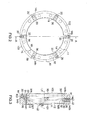
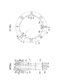
- a coupling opening 11 is defined in an annular main body 10 which has two opposite end surfaces 101/102.
- a thread portion 12 is defined on the inner wall of the coupling opening 11 to be bolted onto a shaft 40 in order for the end surface 101 to lean against a work piece 41 on the shaft 40 (if the shaft 40 is a turning shaft, the work piece 41 is a bearing located between the shaft 40 and the machine parts) and to maintain superb support between the shaft 40 and the work piece 41.
- the main body 10 are two out of four different types of thru-holes 14/14b/14c/14d with a locking assembly defined within respectively.
- the locking assembly comprises a screw bolt 20. By tightening the screw bolt 20, the locking assembly in the thru-holes 14/14b/14c/14d is driven to tightly lock the main body 10 and the shaft 40 with different modes of locking mechanism.
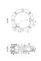
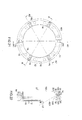
- a coupling opening 11 is defined in an annular main body 10 which has two opposite end surfaces 101/102.
- a thread portion 12 is defined on the inner wall of the coupling opening 11 to be bolted onto a shaft 40 in order for the end surface 101 to lean against a work piece 41 on the shaft 40 and to maintain superb support between the shaft 40 and the work piece 41.
- the locking assembly comprises a screw bolt 20. By tightening the screw bolt 20, the locking assembly in the thru-holes 14/14b/14c/14d is driven to tightly lock the main body 10 and the shaft 40 with different modes of locking mechanism.
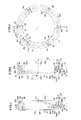
- each cavity 15 defined around the outer periphery of the main body 10 and distributed along the central axis L1 of the main body 10 with equal central angles. One end of each cavity 15 is closed and the other end has an opening 150.
- Each cavity 15 has a first threaded cavity section 151 and a second threaded cavity section 152 orderly aligned therein, one end of the first threaded cavity section 151 is closed, one end of the second threaded cavity section 152 extends to the opening 150, and the other end of the first threaded cavity section 151 and the other end of the second threaded cavity section 152 are linked.
- the first threaded cavity section 151 allows a threaded weighing lump 16 to be bolted in and the second threaded cavity section 152 allows a threaded muffling lump 18 to be bolted in.
- the material of the muffling lump 18 could be high polymer resin, but a preferable embodiment applied in the present invention is polycarbonate fiber (PC fiber) due to its light-weighted and stable quality. Furthermore, when the muffling lump 18 is bolted into the second threaded cavity section 152 of the cavity 15, it could be automatically positioned to avoid being not screwed enough or being over-screwed. The inclination angle of the last thread is reduced for the muffling lump 18 to be stopped and positioned when its last thread reaches the thread of the second threaded cavity section 152. Shown as in FIGs. 6 and 10 , the cavities 15 are defined in the second end surface 102 of the main body 10. As shown in Fig.
- one top end of the muffling lump 18 has a notch 180 extended along a straight line L6 for a screwdriver to be able to bolt the muffling lump 18.
- the direction of the straight line L6 will be a tangent to a circle C 1 which is concentric to the center of the main body 10.
- the first embodiment of the locking assembly includes screw bolts 20 and tightening lumps 30.
- the tightening lumps 30 are mounted in the first thru-hole 14, the second thru-hole 14b and the third thru-hole 14c, and the screw bolts 20 are respectively bolted into the first thru-hole 14, the second thru-hole 14b and the third thru-hole 14c as well.
- Each tightening lump 30 has two opposite end portions 31/32 facing opposite directions. One end portion 31 is pushed by the screw bolt 20 and the other end portion 32 has a tightening surface 320 to lock against the shaft 40.
- the tightening surface 320 is in accord with the wall of the coupling opening 11, it is curved to matches the inner periphery of the coupling opening 11, and it is defined thereon a thread portion 321 which has the same thread size as the thread of the thread portion 12 of the coupling opening 11.
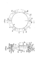
- the second embodiment of the locking assembly includes screw bolts 20 and at least a groove 19.
- a screw bolt 20 When a screw bolt 20 is tightly bolted into a thru-hole 14d, it will compel two sidewalls of the groove 19 to generate a pair of force with opposite directions.
- the inner wall of the coupling opening 11 is partially deformed to force the main body 10 tightly locked on the shaft. Shown as in FIGs.
- groove 19/190 there are two grooves 19/190, the groove 19 is radially recessed from the inner wall of the coupling opening 11, and the groove 190 is radially recessed from the outer periphery of main body 10; the groove 19 is closer to the end surface 102 than the groove 190 is; and the thru-hole 14d is extended along the direction parallel to the central axis of the main body 10 and links both grooves 19/190. Shown as in FIGs.
- grooves 19/190 there are two grooves 19/190, the groove 190 is radially recessed from the outer periphery of main body 10, and the groove 19 is radially recessed from the inner wall of the coupling opening 11; the groove 190 is closer to the end surface 102 than the groove 19 is; and the thru-hole 14d is extended along the direction parallel to the central axis of the main body 10 and links both grooves 19/190. Shown as in FIGs.
- grooves 19/190 there are two grooves 19/190, the groove 190 is radially recessed from the outer periphery of main body 10, and the groove 19 is radially recessed from the inner wall of the coupling opening 11; the groove 190 is closer to the end surface 102 than the groove 19 is; and the thru-hole 14d is extended along the direction parallel to the central axis of the main body 10 and links both grooves 19/190; wherein, a fringe portion 100 which is a part of the main body 10 ranged between the groove 190 and the end surface 102 is defined with an outer smaller diameter; and when the screw bolt 20 is tightly bolted, the coupling opening 11 corresponding to the fringe portion 100 is deformed to firmly clasp onto the shaft 40. Shown as in FIGs.
- each groove 19 laterally penetrates through the main body 10 along the radial direction of the main body 10 and both ends of each groove 19 vertically extend an extended groove 191.
- Each groove 19 also intersects with one thru-hole 14d. When one screw bolt 20 is tightly bolted into one thru-hole 14d, it will compel two sidewalls of the groove 19 to generate a pair of force with opposite directions and to force the inner wall of the coupling opening 11 being partially deformed. Shown as in FIGs.
- each groove 19 and 20 there are four grooves 19 longitudinally distributed around the central axis L1 of the main body 10 with equal distance between each other, each groove 19 has two lateral sides penetrating through the both end surfaces 101, 102 of the main body 10, and has at least one end 192 open, in the embodiment illustrated in the figures, one end 192 of the groove is open, and the other end 193 is closed;
- Each groove 19 also intersects with one thru-hole 14d which is extended from the outer periphery of the main body 10. When one screw bolt 20 is tightly bolted into one thru-hole 14d, it will compel two sidewalls of the groove 19 to generate a pair of force with opposite directions and to force the inner wall of the coupling opening 11 being partially deformed.
- a coupling opening 11, three thru-holes 14 and three thru-holes 14b are defined in an annular main body 10.
- the thru-holes 14 and the thru-holes 14b respectively have a first axial path and a second axial path with respect to the central axis L1 of the main body 10, the shape of the first axial path of the thru-holes 14 and the shape of the second axial path of the thru-holes 14b are different from each other, and three thru-holes 14 and three thru-holes 14b are alternately distributed around the central axis L1 of the main body 10 with equal central angles.
- a locking assembly as depicted in the previous first embodiment is defined within each thru-hole 14 and thru-hole 14b respectively.
- the locking assembly comprises a tightening lump 30 and a screw bolt 20.
- the thru-hole 14 includes two joint first straight portions 140/141 with the same axis which has an included angle B between its axis L2 and the central axis L1 of the main body 10.
- the measure of the included angle B is larger than zero degree and smaller than 90 degree (in one preferable embodiment of the present invention, the measure is designed to be 6zero degree in order to reduce torque caused by tightening the nut and to have better performance of loosening proof).
- the thru-hole 14b includes two joint second straight portions 140b/141b with the same axis which is perpendicular to the central axis L1 of the main body 10 (also the axis of the coupling opening 11).
- the first straight portion 140 and the second straight portion 140b are both extended to the outer periphery of the main body 10 respectively with inner threads for a screw bolt 20 to be bolted in.
- the first straight portion 141 and the second straight portion 141b are both extended to the inner wall of the coupling opening 11 respectively for a tightening lump 30 to be lodged in.
- a coupling opening 11, three thru-holes 14 and three thru-holes 14c are defined in an annular main body 10.
- the thru-holes 14 and the thru-holes 14c respectively have a first axial path and a third axial path with respect to the central axis L1 of the main body 10, the shape of the first axial path of the thru-holes 14 and the shape of the third axial path of the thru-holes 14c are different from each other, and three thru-holes 14 and three thru-holes 14c are alternately distributed around the central axis L1 of the main body 10 with equal central angles.
- a locking assembly as depicted in the previous first embodiment is defined within each thru-hole 14 and thru-hole 14c respectively.
- the locking assembly comprises a tightening lump 30 and a screw bolt 20.
- the thru-hole 14 includes two joint first straight portions 140/141 with the same axis which has an included angle B between itself and the central axis L1 of the main body 10 (also the axis of the coupling opening 11).
- the measure of the included angle B is larger than zero degree and smaller 90 degree.
- the thru-hole 14c includes two joint third straight portions 140c/141c with an included angle C between their axes (the included angle C is 90 degrees shown in the figure).
- the first straight portion 140 is extended to an inclined surface 103 which is located at the intersection of the end surface 102 and the outer periphery of the main body 10, and the third straight portion 140c is extended to the end surface 102.
- the first straight portion 141 and the third straight portion 141c are both extended to the inner wall of the coupling opening 11 respectively.
- the first straight portion 140, extended to the outer periphery of the main body 10, has a different axis relative to the third straight portion 140c and they both have inner threads for screw bolts 20 to be bolted in.
- a vent 142 is extended from the joint of the two third straight portions 140c/141c to the outer periphery of the main body 10.
- a taper portion 21 is defined at the end of the screw bolt 20 in the thru-hole 14c in the embodiment as well.
- At the first end portion 31 of the tightening lump 30 is also a taper portion 33.
- a coupling opening 11, three thru-holes 14b and three thru-holes 14c are defined in an annular main body 10.
- the thru-holes 14b and the thru-holes 14c respectively have an axial path against the central axis L1 of the main body 10, the shapes of the axial paths of the thru-holes 14b and the thru-holes 14c are different from each other, and three thru-holes 14b and three thru-holes 14c are alternately distributed around the central axis L1 of the main body 10 with equal central angles.
- a locking assembly as depicted in the previous first embodiment is defined within each thru-hole 14b and thru-hole 14c respectively.
- the locking assembly comprises one tightening lump 30 and one screw bolt 20.
- the thru-hole 14b includes two joint second straight portions 140b/141b with the same axis L3 which is perpendicular to the central axis L1 of the main body 10 (also the axis L3 is perpendicular to the axis of the coupling opening 11).
- Each thru-hole 14c includes two joint third straight portions 140c/141c with an included angle C between their axes L4 and L5 (the included angle C is 90 degrees shown in the figure).
- the third straight portion 140c is extended to the end surface 102 of the main body 10, and the second straight portion 140b is extended to the outer periphery of the main body 10.
- a taper portion 21 is defined at the end of the screw bolt 20 in the thru-hole 14c in the present embodiment and a taper portion 33 is also defined at the first end portion 31 of the tightening lump 30.
- a coupling opening 11, three thru-holes 14 or three thru-holes 14b or three thru-holes 14c and three thru-holes 14d are defined in an annular main body 10.
- the thru-holes 14 or the thru-holes 14b or the thru-holes 14c and the thru-holes 14d are alternately distributed around the central axis L1 of the main body 10 with equal central angles.
- One locking assembly as depicted in the aforementioned first embodiment is defined within each thru-hole 14b or the thru-holes 14b or the thru-holes 14c, and one locking assembly as depicted in the aforementioned second embodiment is defined within thru-hole 14d respectively.
- the locking assembly in the first embodiment comprises a tightening lump 30 and a screw bolt 20, but the one in the second embodiment comprises a screw bolt 20 and at least a groove 19 radially recessed from the inner wall of the coupling opening 11.
- the thru-hole 14b includes two joint second straight portions 140b/141b with the same axis L3 which is perpendicular to the axis of the central axis L1 of the main body 10 in one embodiment shown as in FIGs. 9 and 10 .
- the thru-hole 14d links through two grooves 19/190 illustrated in the figures 9 and 10 , and the groove 19 is closer to the end surface 102 than the groove 190 is.
- each thru-hole 14d includes two joint third straight portions 140/141 with the same axis L2 which has an included angle B between itself and the central axis L1 of the main body 10 (also the axis L2 is perpendicular to the axis of the coupling opening 11).
- the measure of the included angle B is larger than zero degree and smaller than 90 degree (in one preferable embodiment of the present invention, the measure is designed to be 6zero degrees).
- the thru-hole 14c includes two joint third straight portions 140c/141c with an included angle C between their axes L4, L5 (the included angle C is 90 degrees shown in the figure). Shown as in FIGs. 9 to 20 , the straight portions 140/140b/140c/140d are extended to the outer periphery of the main body 10 and the straight portions 141/141b/141c are extended to the inner wall of the coupling opening 11.
- Each straight portion 140/140b/140c extended to the outer periphery of the main body 10, has inner threads for a screw bolt 20 to be bolted in.
- a coupling opening 11, two thru-holes 14, two thru-holes 14b and two thru-holes 14c are defined in an annular main body 10.
- the thru-holes 14, thru-holes 14b and the thru-holes 14c respectively have a axial path against the central axis L1 of the main body 10, the shapes of the axial paths of the thru-holes 14b, the thru-holes 14b and the thru-holes 14c against the central axis L1 are different from each other, and two thru-holes 14, two thru-holes 14b and two thru-holes 14c are alternately distributed around the central axis L1 of the main body 10 with equal central angles.
- a locking assembly as depicted in the aforementioned first embodiment is defined within each thru-holes 14, thru-hole 14b and thru-hole 14c respectively.
- the locking assembly comprises a tightening lump 30 and a screw bolt 20. Shown as in FIG.
- each thru-hole 14 includes two joint first straight portions 140/141 with the same axis L2 which has an included angle B between itself and the central axis L1 of the main body 10 (also the axis L2 is perpendicular to the axis of the coupling opening 11).
- the measure of the included angle B is larger than zero degree and smaller than 90 degree.
- each thru-hole 14c includes two joint third straight portions 140c/141c with an included angle C between their axes L4 and L5 (the included angle C is 90 degrees shown in the figure).
- the third straight portion 140c is extended to the end surface 102 of the main body 10.
- a taper portion 21 is defined at the end of the screw bolt 20 in the thru-hole 14c in the present embodiment and a taper portion 33 is also defined at the first end portion 31 of the tightening lump 30.
- the taper portion 21 and the taper portion 33 will touch and function in coordination to make the tightening lump 30 be lodged toward the central axis L1 of the main body 10 smoothly.
- each thru-hole 14b includes two joint second straight portions 140b/141b with the same axis L3 which is perpendicular to the central axis L1 of the main body 10 (the included angle E is 90 degrees).
- the first straight portion 140, the second straight portion 140b and the third straight portion 140c are all extended to the outer periphery of the main body 10 respectively, their axes L2, L3 and L4 have different included angles B, E and D against the central axis L1 of the main body 10 respectively, and there are inner threads defined within each of them for one screw bolt 20 to be bolted in.
- the first straight portion 141, the second straight portion 141b and the third straight portion 141c are all extended to the inner wall of the coupling opening 11 respectively for one tightening lump 30 to be lodged in.
- a coupling opening 11, three thru-holes 14, three thru-holes 14b and three thru-holes 14d are defined in an annular main body 10.
- a locking assembly as depicted in the aforementioned first embodiment is defined within each thru-hole 14/14b respectively, and a locking assembly as depicted in the aforementioned second embodiment is defined within each thru-hole 14d.
- a groove 19 is radially recessed from the inner wall of the coupling opening 11 of the main body 10, and it also intersects with the thru-hole 14d.
- each thru-hole 14 includes two joint first straight portions 140/141 with the same axis L2 which has an included angle B between itself and the central axis L1 of the main body 10 (also the axis L2 is perpendicular to the axis of the coupling opening 11).
- the measure of the included angle B is larger than zero degree and smaller than 90 degree.
- each thru-hole 14b includes two joint second straight portions 140b/141b with the same axis L3 which is perpendicular to the central axis L1 of the main body 10 (the included angle E is 90 degrees).
- the first straight portion 140 and the second straight portion 140b are both extended to the outer periphery of the main body 10 respectively with inner threads for a screw bolt 20 to be bolted in.
- the first straight portion 141 and the second straight portion 141b are both extended to the inner wall of the coupling opening 11 respectively for a tightening lump 30 to be lodged in.
Landscapes
- Engineering & Computer Science (AREA)
- General Engineering & Computer Science (AREA)
- Mechanical Engineering (AREA)
- Connection Of Plates (AREA)
- Transmission Devices (AREA)
Applications Claiming Priority (2)
| Application Number | Priority Date | Filing Date | Title |
|---|---|---|---|
| TW099143026A TWI452210B (zh) | 2010-12-09 | 2010-12-09 | 多向全方位鎖制之精密螺帽 |
| TW099144435A TWI461610B (zh) | 2010-12-17 | 2010-12-17 | 複合鎖制之精密螺帽 |
Publications (3)
| Publication Number | Publication Date |
|---|---|
| EP2463530A2 true EP2463530A2 (de) | 2012-06-13 |
| EP2463530A3 EP2463530A3 (de) | 2012-08-22 |
| EP2463530B1 EP2463530B1 (de) | 2017-08-16 |
Family
ID=45815394
Family Applications (1)
| Application Number | Title | Priority Date | Filing Date |
|---|---|---|---|
| EP11164371.4A Not-in-force EP2463530B1 (de) | 2010-12-09 | 2011-04-29 | Präzisionssicherungsmutter mit mehreren Verriegelungsmechanismusmodi |
Country Status (3)
| Country | Link |
|---|---|
| EP (1) | EP2463530B1 (de) |
| JP (1) | JP5254397B2 (de) |
| KR (1) | KR101264784B1 (de) |
Cited By (1)
| Publication number | Priority date | Publication date | Assignee | Title |
|---|---|---|---|---|
| WO2019194876A1 (en) * | 2018-04-05 | 2019-10-10 | Spriggel Daniel John | Locknut |
Citations (2)
| Publication number | Priority date | Publication date | Assignee | Title |
|---|---|---|---|---|
| TWM273418U (en) | 2005-02-04 | 2005-08-21 | Yinsh Prec Ind Co Ltd | High speed spindle and sealing structure for nut thereof |
| TWI262262B (en) | 2004-12-23 | 2006-09-21 | Yinsh Prec Ind Co Ltd | Screw nut for the shaft balance |
Family Cites Families (6)
| Publication number | Priority date | Publication date | Assignee | Title |
|---|---|---|---|---|
| JPS5516522Y2 (de) * | 1975-03-31 | 1980-04-17 | ||
| DD241287A1 (de) * | 1985-09-30 | 1986-12-03 | Werkzeugmasch Forschzent | Verfahren und einrichtung zum sichern von muttern |
| JP2514621Y2 (ja) * | 1991-05-22 | 1996-10-23 | 三菱マテリアル株式会社 | 油圧固定ナット |
| EP0965768B1 (de) * | 1998-06-16 | 2002-09-25 | IBC Industrial Bearings + Components AG | Spannmutter |
| JP3278114B2 (ja) * | 2000-02-10 | 2002-04-30 | エス ケイ エフ メカン アーベー | ロックナット |
| JP3898181B2 (ja) * | 2003-12-15 | 2007-03-28 | 新キャタピラー三菱株式会社 | 流体圧シリンダ装置及び同装置用ピストン締付固定構造 |
-
2011
- 2011-04-22 JP JP2011095612A patent/JP5254397B2/ja not_active Expired - Fee Related
- 2011-04-29 EP EP11164371.4A patent/EP2463530B1/de not_active Not-in-force
- 2011-05-24 KR KR1020110049019A patent/KR101264784B1/ko not_active Expired - Fee Related
Patent Citations (2)
| Publication number | Priority date | Publication date | Assignee | Title |
|---|---|---|---|---|
| TWI262262B (en) | 2004-12-23 | 2006-09-21 | Yinsh Prec Ind Co Ltd | Screw nut for the shaft balance |
| TWM273418U (en) | 2005-02-04 | 2005-08-21 | Yinsh Prec Ind Co Ltd | High speed spindle and sealing structure for nut thereof |
Cited By (1)
| Publication number | Priority date | Publication date | Assignee | Title |
|---|---|---|---|---|
| WO2019194876A1 (en) * | 2018-04-05 | 2019-10-10 | Spriggel Daniel John | Locknut |
Also Published As
| Publication number | Publication date |
|---|---|
| EP2463530B1 (de) | 2017-08-16 |
| KR20120064605A (ko) | 2012-06-19 |
| JP2012122606A (ja) | 2012-06-28 |
| EP2463530A3 (de) | 2012-08-22 |
| JP5254397B2 (ja) | 2013-08-07 |
| KR101264784B1 (ko) | 2013-05-21 |
Similar Documents
| Publication | Publication Date | Title |
|---|---|---|
| US9486900B2 (en) | Screw drive design | |
| EP2699807B1 (de) | Schraubverbindung | |
| CN101058122A (zh) | 用于切屑去除加工的工具以及用于该工具的部件和螺纹接头 | |
| NO179955B (no) | Elliptisk knastformet drivsystem | |
| EP2463530A2 (de) | Präzisionssicherungsmutter mit mehreren Verriegelungsmechanismusmodi | |
| CN105257658A (zh) | 一种电力计量维修用防拆卸螺丝 | |
| US20080019800A1 (en) | Loosening- Proof Method Used For A Screw Fastening Unit And The Device Thereof | |
| TWI452210B (zh) | 多向全方位鎖制之精密螺帽 | |
| CN204505133U (zh) | 具有双冲击块冲击组的气动工具 | |
| CN219605788U (zh) | 一种防松动螺钉 | |
| CN216009200U (zh) | 一种快换水处理膜测试单元螺母 | |
| CN206802048U (zh) | 一种轴螺母 | |
| CN217255905U (zh) | 扳拧槽、紧固件和紧固工具 | |
| EP2543896A1 (de) | Schraube für präzises Anziehen | |
| CN102513974B (zh) | 一种圆头方颈螺栓的专用装卸工具 | |
| CN2868520Y (zh) | 一种有关刀体轴结构改进的手持式电刨 | |
| CN210565647U (zh) | 一种锁紧螺母 | |
| CN203114845U (zh) | 一种对称预压式防松螺母组件 | |
| CN102606600A (zh) | 锁制精密螺帽的平衡结构及其方法 | |
| CN207297580U (zh) | 锥面防松螺母 | |
| US6520883B1 (en) | Eccentric gear | |
| TWI381108B (zh) | Nut lock structure | |
| TWI461610B (zh) | 複合鎖制之精密螺帽 | |
| CN210265454U (zh) | 一种带有自固定式结构的螺母结构 | |
| CN113217521A (zh) | 自变型锁紧螺母 |
Legal Events
| Date | Code | Title | Description |
|---|---|---|---|
| PUAI | Public reference made under article 153(3) epc to a published international application that has entered the european phase |
Free format text: ORIGINAL CODE: 0009012 |
|
| AK | Designated contracting states |
Kind code of ref document: A2 Designated state(s): AL AT BE BG CH CY CZ DE DK EE ES FI FR GB GR HR HU IE IS IT LI LT LU LV MC MK MT NL NO PL PT RO RS SE SI SK SM TR |
|
| AX | Request for extension of the european patent |
Extension state: BA ME |
|
| PUAL | Search report despatched |
Free format text: ORIGINAL CODE: 0009013 |
|
| AK | Designated contracting states |
Kind code of ref document: A3 Designated state(s): AL AT BE BG CH CY CZ DE DK EE ES FI FR GB GR HR HU IE IS IT LI LT LU LV MC MK MT NL NO PL PT RO RS SE SI SK SM TR |
|
| AX | Request for extension of the european patent |
Extension state: BA ME |
|
| RIC1 | Information provided on ipc code assigned before grant |
Ipc: F16B 39/02 20060101ALI20120719BHEP Ipc: F16B 37/00 20060101AFI20120719BHEP |
|
| 17P | Request for examination filed |
Effective date: 20121211 |
|
| 17Q | First examination report despatched |
Effective date: 20140514 |
|
| GRAP | Despatch of communication of intention to grant a patent |
Free format text: ORIGINAL CODE: EPIDOSNIGR1 |
|
| INTG | Intention to grant announced |
Effective date: 20170223 |
|
| GRAS | Grant fee paid |
Free format text: ORIGINAL CODE: EPIDOSNIGR3 |
|
| GRAA | (expected) grant |
Free format text: ORIGINAL CODE: 0009210 |
|
| AK | Designated contracting states |
Kind code of ref document: B1 Designated state(s): AL AT BE BG CH CY CZ DE DK EE ES FI FR GB GR HR HU IE IS IT LI LT LU LV MC MK MT NL NO PL PT RO RS SE SI SK SM TR |
|
| REG | Reference to a national code |
Ref country code: GB Ref legal event code: FG4D |
|
| REG | Reference to a national code |
Ref country code: CH Ref legal event code: EP |
|
| REG | Reference to a national code |
Ref country code: IE Ref legal event code: FG4D |
|
| REG | Reference to a national code |
Ref country code: AT Ref legal event code: REF Ref document number: 919357 Country of ref document: AT Kind code of ref document: T Effective date: 20170915 |
|
| REG | Reference to a national code |
Ref country code: DE Ref legal event code: R096 Ref document number: 602011040560 Country of ref document: DE |
|
| REG | Reference to a national code |
Ref country code: NL Ref legal event code: MP Effective date: 20170816 |
|
| REG | Reference to a national code |
Ref country code: LT Ref legal event code: MG4D |
|
| REG | Reference to a national code |
Ref country code: AT Ref legal event code: MK05 Ref document number: 919357 Country of ref document: AT Kind code of ref document: T Effective date: 20170816 |
|
| PG25 | Lapsed in a contracting state [announced via postgrant information from national office to epo] |
Ref country code: NL Free format text: LAPSE BECAUSE OF FAILURE TO SUBMIT A TRANSLATION OF THE DESCRIPTION OR TO PAY THE FEE WITHIN THE PRESCRIBED TIME-LIMIT Effective date: 20170816 Ref country code: LT Free format text: LAPSE BECAUSE OF FAILURE TO SUBMIT A TRANSLATION OF THE DESCRIPTION OR TO PAY THE FEE WITHIN THE PRESCRIBED TIME-LIMIT Effective date: 20170816 Ref country code: AT Free format text: LAPSE BECAUSE OF FAILURE TO SUBMIT A TRANSLATION OF THE DESCRIPTION OR TO PAY THE FEE WITHIN THE PRESCRIBED TIME-LIMIT Effective date: 20170816 Ref country code: SE Free format text: LAPSE BECAUSE OF FAILURE TO SUBMIT A TRANSLATION OF THE DESCRIPTION OR TO PAY THE FEE WITHIN THE PRESCRIBED TIME-LIMIT Effective date: 20170816 Ref country code: FI Free format text: LAPSE BECAUSE OF FAILURE TO SUBMIT A TRANSLATION OF THE DESCRIPTION OR TO PAY THE FEE WITHIN THE PRESCRIBED TIME-LIMIT Effective date: 20170816 Ref country code: NO Free format text: LAPSE BECAUSE OF FAILURE TO SUBMIT A TRANSLATION OF THE DESCRIPTION OR TO PAY THE FEE WITHIN THE PRESCRIBED TIME-LIMIT Effective date: 20171116 |
|
| PG25 | Lapsed in a contracting state [announced via postgrant information from national office to epo] |
Ref country code: ES Free format text: LAPSE BECAUSE OF FAILURE TO SUBMIT A TRANSLATION OF THE DESCRIPTION OR TO PAY THE FEE WITHIN THE PRESCRIBED TIME-LIMIT Effective date: 20170816 Ref country code: PL Free format text: LAPSE BECAUSE OF FAILURE TO SUBMIT A TRANSLATION OF THE DESCRIPTION OR TO PAY THE FEE WITHIN THE PRESCRIBED TIME-LIMIT Effective date: 20170816 Ref country code: IS Free format text: LAPSE BECAUSE OF FAILURE TO SUBMIT A TRANSLATION OF THE DESCRIPTION OR TO PAY THE FEE WITHIN THE PRESCRIBED TIME-LIMIT Effective date: 20171216 Ref country code: GR Free format text: LAPSE BECAUSE OF FAILURE TO SUBMIT A TRANSLATION OF THE DESCRIPTION OR TO PAY THE FEE WITHIN THE PRESCRIBED TIME-LIMIT Effective date: 20171117 Ref country code: RS Free format text: LAPSE BECAUSE OF FAILURE TO SUBMIT A TRANSLATION OF THE DESCRIPTION OR TO PAY THE FEE WITHIN THE PRESCRIBED TIME-LIMIT Effective date: 20170816 Ref country code: BG Free format text: LAPSE BECAUSE OF FAILURE TO SUBMIT A TRANSLATION OF THE DESCRIPTION OR TO PAY THE FEE WITHIN THE PRESCRIBED TIME-LIMIT Effective date: 20171116 Ref country code: LV Free format text: LAPSE BECAUSE OF FAILURE TO SUBMIT A TRANSLATION OF THE DESCRIPTION OR TO PAY THE FEE WITHIN THE PRESCRIBED TIME-LIMIT Effective date: 20170816 |
|
| REG | Reference to a national code |
Ref country code: FR Ref legal event code: PLFP Year of fee payment: 8 |
|
| PG25 | Lapsed in a contracting state [announced via postgrant information from national office to epo] |
Ref country code: DK Free format text: LAPSE BECAUSE OF FAILURE TO SUBMIT A TRANSLATION OF THE DESCRIPTION OR TO PAY THE FEE WITHIN THE PRESCRIBED TIME-LIMIT Effective date: 20170816 Ref country code: CZ Free format text: LAPSE BECAUSE OF FAILURE TO SUBMIT A TRANSLATION OF THE DESCRIPTION OR TO PAY THE FEE WITHIN THE PRESCRIBED TIME-LIMIT Effective date: 20170816 Ref country code: RO Free format text: LAPSE BECAUSE OF FAILURE TO SUBMIT A TRANSLATION OF THE DESCRIPTION OR TO PAY THE FEE WITHIN THE PRESCRIBED TIME-LIMIT Effective date: 20170816 |
|
| REG | Reference to a national code |
Ref country code: DE Ref legal event code: R097 Ref document number: 602011040560 Country of ref document: DE |
|
| PG25 | Lapsed in a contracting state [announced via postgrant information from national office to epo] |
Ref country code: IT Free format text: LAPSE BECAUSE OF FAILURE TO SUBMIT A TRANSLATION OF THE DESCRIPTION OR TO PAY THE FEE WITHIN THE PRESCRIBED TIME-LIMIT Effective date: 20170816 Ref country code: SM Free format text: LAPSE BECAUSE OF FAILURE TO SUBMIT A TRANSLATION OF THE DESCRIPTION OR TO PAY THE FEE WITHIN THE PRESCRIBED TIME-LIMIT Effective date: 20170816 Ref country code: SK Free format text: LAPSE BECAUSE OF FAILURE TO SUBMIT A TRANSLATION OF THE DESCRIPTION OR TO PAY THE FEE WITHIN THE PRESCRIBED TIME-LIMIT Effective date: 20170816 Ref country code: EE Free format text: LAPSE BECAUSE OF FAILURE TO SUBMIT A TRANSLATION OF THE DESCRIPTION OR TO PAY THE FEE WITHIN THE PRESCRIBED TIME-LIMIT Effective date: 20170816 |
|
| PLBE | No opposition filed within time limit |
Free format text: ORIGINAL CODE: 0009261 |
|
| STAA | Information on the status of an ep patent application or granted ep patent |
Free format text: STATUS: NO OPPOSITION FILED WITHIN TIME LIMIT |
|
| 26N | No opposition filed |
Effective date: 20180517 |
|
| PG25 | Lapsed in a contracting state [announced via postgrant information from national office to epo] |
Ref country code: SI Free format text: LAPSE BECAUSE OF FAILURE TO SUBMIT A TRANSLATION OF THE DESCRIPTION OR TO PAY THE FEE WITHIN THE PRESCRIBED TIME-LIMIT Effective date: 20170816 |
|
| PG25 | Lapsed in a contracting state [announced via postgrant information from national office to epo] |
Ref country code: MC Free format text: LAPSE BECAUSE OF FAILURE TO SUBMIT A TRANSLATION OF THE DESCRIPTION OR TO PAY THE FEE WITHIN THE PRESCRIBED TIME-LIMIT Effective date: 20170816 |
|
| REG | Reference to a national code |
Ref country code: BE Ref legal event code: MM Effective date: 20180430 |
|
| REG | Reference to a national code |
Ref country code: IE Ref legal event code: MM4A |
|
| PG25 | Lapsed in a contracting state [announced via postgrant information from national office to epo] |
Ref country code: BE Free format text: LAPSE BECAUSE OF NON-PAYMENT OF DUE FEES Effective date: 20180430 |
|
| PG25 | Lapsed in a contracting state [announced via postgrant information from national office to epo] |
Ref country code: IE Free format text: LAPSE BECAUSE OF NON-PAYMENT OF DUE FEES Effective date: 20180429 |
|
| PG25 | Lapsed in a contracting state [announced via postgrant information from national office to epo] |
Ref country code: MT Free format text: LAPSE BECAUSE OF NON-PAYMENT OF DUE FEES Effective date: 20180429 |
|
| PG25 | Lapsed in a contracting state [announced via postgrant information from national office to epo] |
Ref country code: TR Free format text: LAPSE BECAUSE OF FAILURE TO SUBMIT A TRANSLATION OF THE DESCRIPTION OR TO PAY THE FEE WITHIN THE PRESCRIBED TIME-LIMIT Effective date: 20170816 |
|
| PG25 | Lapsed in a contracting state [announced via postgrant information from national office to epo] |
Ref country code: PT Free format text: LAPSE BECAUSE OF FAILURE TO SUBMIT A TRANSLATION OF THE DESCRIPTION OR TO PAY THE FEE WITHIN THE PRESCRIBED TIME-LIMIT Effective date: 20170816 Ref country code: HU Free format text: LAPSE BECAUSE OF FAILURE TO SUBMIT A TRANSLATION OF THE DESCRIPTION OR TO PAY THE FEE WITHIN THE PRESCRIBED TIME-LIMIT; INVALID AB INITIO Effective date: 20110429 |
|
| PG25 | Lapsed in a contracting state [announced via postgrant information from national office to epo] |
Ref country code: CY Free format text: LAPSE BECAUSE OF FAILURE TO SUBMIT A TRANSLATION OF THE DESCRIPTION OR TO PAY THE FEE WITHIN THE PRESCRIBED TIME-LIMIT Effective date: 20170816 Ref country code: MK Free format text: LAPSE BECAUSE OF NON-PAYMENT OF DUE FEES Effective date: 20170816 Ref country code: HR Free format text: LAPSE BECAUSE OF FAILURE TO SUBMIT A TRANSLATION OF THE DESCRIPTION OR TO PAY THE FEE WITHIN THE PRESCRIBED TIME-LIMIT Effective date: 20170816 |
|
| PG25 | Lapsed in a contracting state [announced via postgrant information from national office to epo] |
Ref country code: AL Free format text: LAPSE BECAUSE OF FAILURE TO SUBMIT A TRANSLATION OF THE DESCRIPTION OR TO PAY THE FEE WITHIN THE PRESCRIBED TIME-LIMIT Effective date: 20170816 |
|
| PGFP | Annual fee paid to national office [announced via postgrant information from national office to epo] |
Ref country code: LU Payment date: 20210421 Year of fee payment: 11 |
|
| PGFP | Annual fee paid to national office [announced via postgrant information from national office to epo] |
Ref country code: DE Payment date: 20210426 Year of fee payment: 11 Ref country code: FR Payment date: 20210421 Year of fee payment: 11 |
|
| PGFP | Annual fee paid to national office [announced via postgrant information from national office to epo] |
Ref country code: CH Payment date: 20210426 Year of fee payment: 11 Ref country code: GB Payment date: 20210420 Year of fee payment: 11 |
|
| REG | Reference to a national code |
Ref country code: DE Ref legal event code: R119 Ref document number: 602011040560 Country of ref document: DE |
|
| REG | Reference to a national code |
Ref country code: CH Ref legal event code: PL |
|
| GBPC | Gb: european patent ceased through non-payment of renewal fee |
Effective date: 20220429 |
|
| PG25 | Lapsed in a contracting state [announced via postgrant information from national office to epo] |
Ref country code: LU Free format text: LAPSE BECAUSE OF NON-PAYMENT OF DUE FEES Effective date: 20220429 Ref country code: LI Free format text: LAPSE BECAUSE OF NON-PAYMENT OF DUE FEES Effective date: 20220430 Ref country code: GB Free format text: LAPSE BECAUSE OF NON-PAYMENT OF DUE FEES Effective date: 20220429 Ref country code: FR Free format text: LAPSE BECAUSE OF NON-PAYMENT OF DUE FEES Effective date: 20220430 Ref country code: DE Free format text: LAPSE BECAUSE OF NON-PAYMENT OF DUE FEES Effective date: 20221103 Ref country code: CH Free format text: LAPSE BECAUSE OF NON-PAYMENT OF DUE FEES Effective date: 20220430 |