EP2461994B1 - Verfahren und vorrichtung zum erkennen eines auslösens einer kupplung in einem klappenantrieb - Google Patents
Verfahren und vorrichtung zum erkennen eines auslösens einer kupplung in einem klappenantrieb Download PDFInfo
- Publication number
- EP2461994B1 EP2461994B1 EP10739545A EP10739545A EP2461994B1 EP 2461994 B1 EP2461994 B1 EP 2461994B1 EP 10739545 A EP10739545 A EP 10739545A EP 10739545 A EP10739545 A EP 10739545A EP 2461994 B1 EP2461994 B1 EP 2461994B1
- Authority
- EP
- European Patent Office
- Prior art keywords
- flap
- clutch
- drive motor
- gradient
- speed
- Prior art date
- Legal status (The legal status is an assumption and is not a legal conclusion. Google has not performed a legal analysis and makes no representation as to the accuracy of the status listed.)
- Not-in-force
Links
Images

Classifications
-
- E—FIXED CONSTRUCTIONS
- E05—LOCKS; KEYS; WINDOW OR DOOR FITTINGS; SAFES
- E05F—DEVICES FOR MOVING WINGS INTO OPEN OR CLOSED POSITION; CHECKS FOR WINGS; WING FITTINGS NOT OTHERWISE PROVIDED FOR, CONCERNED WITH THE FUNCTIONING OF THE WING
- E05F15/00—Power-operated mechanisms for wings
- E05F15/40—Safety devices, e.g. detection of obstructions or end positions
- E05F15/41—Detection by monitoring transmitted force or torque; Safety couplings with activation dependent upon torque or force, e.g. slip couplings
-
- B—PERFORMING OPERATIONS; TRANSPORTING
- B60—VEHICLES IN GENERAL
- B60J—WINDOWS, WINDSCREENS, NON-FIXED ROOFS, DOORS, OR SIMILAR DEVICES FOR VEHICLES; REMOVABLE EXTERNAL PROTECTIVE COVERINGS SPECIALLY ADAPTED FOR VEHICLES
- B60J5/00—Doors
- B60J5/10—Doors arranged at the vehicle rear
- B60J5/101—Doors arranged at the vehicle rear for non-load transporting vehicles, i.e. family cars including vans
-
- E—FIXED CONSTRUCTIONS
- E05—LOCKS; KEYS; WINDOW OR DOOR FITTINGS; SAFES
- E05F—DEVICES FOR MOVING WINGS INTO OPEN OR CLOSED POSITION; CHECKS FOR WINGS; WING FITTINGS NOT OTHERWISE PROVIDED FOR, CONCERNED WITH THE FUNCTIONING OF THE WING
- E05F15/00—Power-operated mechanisms for wings
- E05F15/60—Power-operated mechanisms for wings using electrical actuators
- E05F15/603—Power-operated mechanisms for wings using electrical actuators using rotary electromotors
- E05F15/611—Power-operated mechanisms for wings using electrical actuators using rotary electromotors for swinging wings
- E05F15/616—Power-operated mechanisms for wings using electrical actuators using rotary electromotors for swinging wings operated by push-pull mechanisms
- E05F15/622—Power-operated mechanisms for wings using electrical actuators using rotary electromotors for swinging wings operated by push-pull mechanisms using screw-and-nut mechanisms
-
- E—FIXED CONSTRUCTIONS
- E05—LOCKS; KEYS; WINDOW OR DOOR FITTINGS; SAFES
- E05Y—INDEXING SCHEME ASSOCIATED WITH SUBCLASSES E05D AND E05F, RELATING TO CONSTRUCTION ELEMENTS, ELECTRIC CONTROL, POWER SUPPLY, POWER SIGNAL OR TRANSMISSION, USER INTERFACES, MOUNTING OR COUPLING, DETAILS, ACCESSORIES, AUXILIARY OPERATIONS NOT OTHERWISE PROVIDED FOR, APPLICATION THEREOF
- E05Y2201/00—Constructional elements; Accessories therefor
- E05Y2201/20—Brakes; Disengaging means; Holders; Stops; Valves; Accessories therefor
- E05Y2201/214—Disengaging means
- E05Y2201/216—Clutches
-
- E—FIXED CONSTRUCTIONS
- E05—LOCKS; KEYS; WINDOW OR DOOR FITTINGS; SAFES
- E05Y—INDEXING SCHEME ASSOCIATED WITH SUBCLASSES E05D AND E05F, RELATING TO CONSTRUCTION ELEMENTS, ELECTRIC CONTROL, POWER SUPPLY, POWER SIGNAL OR TRANSMISSION, USER INTERFACES, MOUNTING OR COUPLING, DETAILS, ACCESSORIES, AUXILIARY OPERATIONS NOT OTHERWISE PROVIDED FOR, APPLICATION THEREOF
- E05Y2201/00—Constructional elements; Accessories therefor
- E05Y2201/20—Brakes; Disengaging means; Holders; Stops; Valves; Accessories therefor
- E05Y2201/23—Actuation thereof
- E05Y2201/232—Actuation thereof by automatically acting means
- E05Y2201/236—Actuation thereof by automatically acting means using force or torque
-
- E—FIXED CONSTRUCTIONS
- E05—LOCKS; KEYS; WINDOW OR DOOR FITTINGS; SAFES
- E05Y—INDEXING SCHEME ASSOCIATED WITH SUBCLASSES E05D AND E05F, RELATING TO CONSTRUCTION ELEMENTS, ELECTRIC CONTROL, POWER SUPPLY, POWER SIGNAL OR TRANSMISSION, USER INTERFACES, MOUNTING OR COUPLING, DETAILS, ACCESSORIES, AUXILIARY OPERATIONS NOT OTHERWISE PROVIDED FOR, APPLICATION THEREOF
- E05Y2400/00—Electronic control; Electrical power; Power supply; Power or signal transmission; User interfaces
- E05Y2400/10—Electronic control
- E05Y2400/32—Position control, detection or monitoring
- E05Y2400/322—Position control, detection or monitoring by using absolute position sensors
- E05Y2400/326—Position control, detection or monitoring by using absolute position sensors of the angular type
-
- E—FIXED CONSTRUCTIONS
- E05—LOCKS; KEYS; WINDOW OR DOOR FITTINGS; SAFES
- E05Y—INDEXING SCHEME ASSOCIATED WITH SUBCLASSES E05D AND E05F, RELATING TO CONSTRUCTION ELEMENTS, ELECTRIC CONTROL, POWER SUPPLY, POWER SIGNAL OR TRANSMISSION, USER INTERFACES, MOUNTING OR COUPLING, DETAILS, ACCESSORIES, AUXILIARY OPERATIONS NOT OTHERWISE PROVIDED FOR, APPLICATION THEREOF
- E05Y2600/00—Mounting or coupling arrangements for elements provided for in this subclass
- E05Y2600/50—Mounting methods; Positioning
- E05Y2600/56—Positioning, e.g. re-positioning, or pre-mounting
-
- E—FIXED CONSTRUCTIONS
- E05—LOCKS; KEYS; WINDOW OR DOOR FITTINGS; SAFES
- E05Y—INDEXING SCHEME ASSOCIATED WITH SUBCLASSES E05D AND E05F, RELATING TO CONSTRUCTION ELEMENTS, ELECTRIC CONTROL, POWER SUPPLY, POWER SIGNAL OR TRANSMISSION, USER INTERFACES, MOUNTING OR COUPLING, DETAILS, ACCESSORIES, AUXILIARY OPERATIONS NOT OTHERWISE PROVIDED FOR, APPLICATION THEREOF
- E05Y2800/00—Details, accessories and auxiliary operations not otherwise provided for
-
- E—FIXED CONSTRUCTIONS
- E05—LOCKS; KEYS; WINDOW OR DOOR FITTINGS; SAFES
- E05Y—INDEXING SCHEME ASSOCIATED WITH SUBCLASSES E05D AND E05F, RELATING TO CONSTRUCTION ELEMENTS, ELECTRIC CONTROL, POWER SUPPLY, POWER SIGNAL OR TRANSMISSION, USER INTERFACES, MOUNTING OR COUPLING, DETAILS, ACCESSORIES, AUXILIARY OPERATIONS NOT OTHERWISE PROVIDED FOR, APPLICATION THEREOF
- E05Y2800/00—Details, accessories and auxiliary operations not otherwise provided for
- E05Y2800/74—Specific positions
- E05Y2800/748—Specific positions end
-
- E—FIXED CONSTRUCTIONS
- E05—LOCKS; KEYS; WINDOW OR DOOR FITTINGS; SAFES
- E05Y—INDEXING SCHEME ASSOCIATED WITH SUBCLASSES E05D AND E05F, RELATING TO CONSTRUCTION ELEMENTS, ELECTRIC CONTROL, POWER SUPPLY, POWER SIGNAL OR TRANSMISSION, USER INTERFACES, MOUNTING OR COUPLING, DETAILS, ACCESSORIES, AUXILIARY OPERATIONS NOT OTHERWISE PROVIDED FOR, APPLICATION THEREOF
- E05Y2900/00—Application of doors, windows, wings or fittings thereof
- E05Y2900/50—Application of doors, windows, wings or fittings thereof for vehicles
- E05Y2900/53—Type of wing
- E05Y2900/546—Tailboards, tailgates or sideboards opening upwards
Definitions
- the invention relates to damper actuators, such as trunk flaps and vehicle doors of a motor vehicle, which are electrically operated.
- Flap systems for electrical opening and closing are used in motor vehicles in trunk systems or vehicle doors. Triggered by the actuation of a control element, such as e.g. a switch, in the passenger compartment of the motor vehicle or by a radio control element, an electric motor is activated to open the door.
- the electric motor is connected to the respective flap (vehicle door, boot lid and the like) via a spindle gear or the like to provide a corresponding speed and force for the opening operation.
- a closing operation can also be triggered by a corresponding control element or radio control element or by pressing the flap in the closing direction. Furthermore, it can be provided that when the flap is pressed in the closing direction, the movement of the flap over the corresponding one causes a rotation of the electric motor, which thereby generates a generator current. It can be provided that the generated generator current triggers the closing process, so that the electric motor is driven to close the flap and this is closed accordingly.
- applying a force to the closure member causes rotation of the electric motor.
- a threshold is exceeded, e.g. when a user applies a high force to open or close the flap, or the flap encounters resistance in a movement driven by the electric motor, a clutch, in particular a slip clutch, is provided between the electric motor and the gear coupled to the flap from the action of a certain force (above a trigger threshold) triggers.
- the triggering of the clutch causes the movement of the flap to be decoupled from the movement of the electric motor.
- the previously non-positive connection between the flap and the electric motor is interrupted when the clutch is triggered in a damper drive.
- a function is usually realized with which a maximum open position of the flap can be programmed by a user.
- the position of the flap In order to ensure that the position of the maximum open position is not exceeded, the position of the flap must be known at all times in the control unit which actuates the flap system. By determining the absolute rotor position of the electric motor and assigning it to a flap position, this is usually possible.
- a triggering of the clutch can result in a flap system in which the position of the flap is not determined directly but only via the position of the rotor of the electric motor, the position information for the flap is lost. Therefore, it is necessary to recognize the timing of the release of the clutch to determine when the position information for the determination of the flap position can no longer be used.
- An adjusting unit for a tailgate in which a sensor determines a rotational speed of a movable part in a reference position. The derivative of the rotational speed with time is compared with a value whereby an obstacle is detected when there is a deviation between the threshold value and the determined derivative.
- An idea of the invention is to detect by mere monitoring of the adjustment speed of the drive motor, such as a speed of an electric motor, when the clutch triggers and thereby breaks the power transmission to the flap.
- the clutch When exerting a force on the flap, for example, by manual operation or stop the flap on a resistor triggers after overcoming the static friction, the clutch and the power transmission through the clutch is canceled or significantly reduced.
- the adjustment speed of the drive motor changes, in particular the speed of an electric motor, since there is a significant rapid change in the load torque. This is usually independent of whether the speed of the electric motor is regulated or not. If a gradient of the adjustment speed is detected, which is above a gradient threshold, it can be assumed that the clutch is triggered.
- a function of the flap system for starting a maximum opening height defined by the user can be deactivated. Furthermore, it can be provided that when a triggering of the clutch is detected, a driving of the drive motor is only allowed in the closing direction of the flap.
- the position of the flap is detected via a position of a rotor of the drive motor.
- the position of the flap in the method of the flap, can be limited to a maximum open position.
- the flap when a release of the clutch is detected, the flap is moved in the closing direction to an end position, wherein when the flap has reached the end position, the position of the flap is assigned to a rotor position of the drive motor.
- FIG. 1 shows a rear part of a motor vehicle 1 with a trunk 2, which is closed by a trunk lid 3.
- the trunk lid 3 can be opened or closed by an electric drive system 4.
- the drive system 4 comprises an electric motor 5, which is mechanically coupled to a transmission 6.
- a rotational movement of an output shaft 11 of the electric motor 5 is converted in the transmission 6 in a translational movement of a linkage 7, which engages the trunk lid 3.
- a spindle 10 moves in a cylinder 9 of a transmission 6, so that the entire length of the linkage 7 changes.
- the clutch 8 is designed as a conventional clutch, for example, with two clutch plates 12 which are pressed against each other with a force, so as to achieve a coupling for transmitting a torque by a static friction force.
- the clutch 8 is dimensioned so that it triggers a sufficiently large release force in the direction of movement of the linkage 7, ie a force acting on the linkage 7 force, or at a sufficiently high release torque acting on clutch plates.
- the coupling may also be provided between the transmission 6 and the linkage 7.
- it may be, for example, a plate coupling, in which two plates are pressed against each other, so that when exceeded by the resulting static friction, the plates move against each other and thereby the length of the linkage 7 is changed.
- the drive system 4 is controlled electrically by a control unit 15 via corresponding supply lines 16.
- the controller 15 is in communication with controls (not shown) through which the user can indicate whether the trunk lid 3 should be opened or closed. Furthermore, the control unit 15 detects via a corresponding signal line from the electric motor 5, a position signal PS indicating the absolute position of a rotor of the electric motor 5.
- the position signal PS may be provided by a position sensor (not shown) disposed on the electric motor 5.
- the position signal PS is used to determine the current position of the trunk lid 3. This is done via a defined assignment of the current position of the rotor of the electric motor 5 to a position of the trunk lid 3. To do this, a defined fixed coupling between the rotor of the electric motor 5 and the position of the boot lid 3 is necessary.
- the boot lid 3 To recalibrate the boot lid 3, it must be moved to a defined position or completely closed.
- the defined position must be detectable, i. e.g. the state of complete closure of the boot lid 3 must be detectable, for example by an increase in the current through the electric motor 5 when the boot lid 3 is blocked by an end stop.
- the end stop can also be signaled to the control unit 9 by a corresponding sensor.
- the calibration process should not be done often for convenience. It is now intended to detect when the clutch has triggered, and preferably make a calibration only when triggered clutch. For this purpose, the rotational speed of the electric motor 5 is monitored, for example, by evaluating the position signal PS and closed based on a change in the speed signal to a triggering of the clutch 8. An indication of the speed may e.g. derived from a detected position information by a change in position over a defined time window is determined. By a time derivative of the specification of the speed can thereby be detected a speed change.
- Tripping results in a rapid change in the speed of the electric motor 5. If the force acts on the trunk lid 3 in the direction of an adjusting movement of the electric motor 5, the electric motor 5 initially becomes faster due to the action of the force on the trunk lid 3; when the clutch 8 is triggered, however, the coupling between the movement of the trunk lid 3 and the rotary movement of the electric motor 5 is greatly reduced, so that the torque acting on the transmission drops and thus the speed suddenly decreases. The amount of the gradient of the speed change then exceeds a certain speed gradient threshold and it can be concluded that the clutch 8 is triggered.
- the electric motor 5 is initially slower until the clutch 8 triggers. After triggering the clutch 8, the speed suddenly becomes faster, wherein the then present speed gradient exceeds the speed gradient threshold.
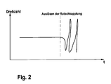
- FIG. 2 shows the speed curve before and after a triggering of such a clutch 8, when the rotational speed of the electric motor 5 is regulated by a control. Due to the high magnitude of the speed gradient after the clutch 8 has tripped, there is a strong intervention in the control which results in the control oscillating. This is from the FIG. 2 easily recognizable.
- a method of the trunk lid 3 with the aid of the drive system 4 is permitted only in the direction of the closed position in order to avoid a user-defined maximum position, ie opening position of the trunk lid 3, is not exceeded. As a result, any damage to the boot lid 3 can be avoided.
- the method described above can basically be applied to all electrically operable opening mechanisms in which a flap can be moved in front of an opening in order to open or close the opening.
Landscapes
- Engineering & Computer Science (AREA)
- Mechanical Engineering (AREA)
- Power-Operated Mechanisms For Wings (AREA)
- Superstructure Of Vehicle (AREA)
- Hydraulic Clutches, Magnetic Clutches, Fluid Clutches, And Fluid Joints (AREA)
- Vehicle Step Arrangements And Article Storage (AREA)
Description
- Die Erfindung betrifft Klappenantriebe, wie beispielsweise Kofferraumklappen und Fahrzeugtüren eines Kraftfahrzeugs, die elektrisch bedienbar sind.
- Klappensysteme zum elektrischen Öffnen und Schließen werden in Kraftfahrzeugen bei Kofferraumsystemen oder Fahrzeugtüren eingesetzt. Ausgelöst durch die Betätigung eines Bedienelements, wie z.B. einem Schalter, im Fahrgastraum des Kraftfahrzeugs oder durch ein Funkbedienelement wird ein Elektromotor aktiviert, um die Klappe zu öffnen. Der Elektromotor steht mit der jeweiligen Klappe (Fahrzeugtür, Kofferraumklappe und dergleichen) über ein Spindelgetriebe oder dergleichen in Verbindung, um eine entsprechende Geschwindigkeit und Kraft für den Öffnungsvorgang zur Verfügung zu stellen.
- Ein Schließvorgang kann ebenfalls durch ein entsprechendes Bedienelement bzw. Funkbedienelement oder auch durch ein Drücken der Klappe in Schließrichtung ausgelöst werden. Weiterhin kann vorgesehen sein, dass beim Drücken der Klappe in Schließrichtung die Bewegung der Klappe über das entsprechende eine Drehung des Elektromotors bewirkt, der dadurch einen Generatorstrom erzeugt. Es kann vorgesehen werden, dass der erzeugte Generatorstrom den Schließvorgang triggert, so dass der Elektromotor zum Schließen der Klappe angesteuert wird und diese entsprechend geschlossen wird.
- Im Allgemeinen bewirkt ein Ausüben einer Kraft auf das Schließelement eine Drehung des Elektromotors. Für den Fall, dass bei Ausüben einer Kraft auf das Schließelement, ein Schwellenwert überschritten wird, z.B. wenn ein Benutzer zum Öffnen oder Schließen der Klappe eine hohe Kraft aufwendet, oder die Klappe bei einer durch den Elektromotor angetriebenen Bewegung auf einen Widerstand stößt, ist zwischen dem Elektromotor und dem mit der der Klappe gekoppelten Getriebe eine Kupplung insbesondere eine Rutschkupplung, vorgesehen, die ab dem Wirken einer bestimmten Kraft (über einem Auslöseschwellenwert) auslöst. Das Auslösen der Kupplung bewirkt, dass die Bewegung der Klappe von der Bewegung des Elektromotors entkoppelt wird. Mit anderen Worten wird beim Auslösen der Kupplung in einem Klappenantrieb die zuvor kraftschlüssige Verbindung zwischen der Klappe und dem Elektromotor unterbrochen.
- Bei elektrisch angetriebenen Klappensystemen wird üblicherweise eine Funktion realisiert, mit der eine maximale Offenstellung der Klappe von einem Benutzer programmiert werden kann. Um zu gewährleisten, dass die Position der maximalen Offenstellung nicht überschritten wird, muss die Position der Klappe jederzeit in dem das Klappensystem ansteuernden Steuergerät bekannt sein. Durch Feststellen der absoluten Rotorlage des Elektromotors und Zuordnen zu einer Klappenstellung ist dies in der Regel möglich. Ein Auslösen der Kupplung kann jedoch dazu führen, dass bei einem Klappensystem, bei dem die Stellung der Klappe nicht unmittelbar sondern nur über die Position des Rotors des Elektromotors bestimmt wird, die Positionsinformation für die Klappe verloren geht. Daher ist es notwendig, den Zeitpunkt des Auslösens der Kupplung zu erkennen, um festzustellen, wann die Positionsinformation für die Bestimmung der Klappenstellung nicht länger verwendet werden kann.
- Aus der
US 2001/035725 A1 ist bereits eine Verstelleinheit für eine Heckklappe bekannt, bei dem ein Sensor eine Drehgeschwindigkeit eines beweglichen Teils in einer Referenzlage bestimmt. Die Ableitung der Drehgeschwindigkeit nach der Zeit wird mit einem Wert verglichen, wobei ein Hindernis erkannt wird, wenn eine Abweichung zwischen dem Schwellwert und der ermittelten Ableitung besteht. - Es ist Aufgabe der vorliegenden Erfindung, ein Verfahren und eine Vorrichtung zum Erkennen eines Auslösens einer Kupplung in einem Klappensystem zur Verfügung zu stellen.
- Diese Aufgabe wird durch das Verfahren gemäß Anspruch 1 und die Vorrichtung gemäß dem nebengeordneten Anspruch gelöst.
- Weitere vorteilhafte Ausgestaltungen sind in den abhängigen Ansprüchen angegeben.
- Gemäß einem ersten Aspekt ist ein Verfahren zum Feststellen eines Auslösens einer Kupplung in einem Klappenantrieb vorgesehen. Dabei koppelt die Kupplung einen Antriebsmotor mit einer verstellbaren Klappe, so dass die Klappe mit Hilfe des Antriebsmotors verstellbar ist, und wobei die Kopplung zwischen dem Antriebsmotor der Klappe unterbrochen wird, wenn eine Kraft oder ein Drehmoment auf die Klappe einen Maximalwert übersteigt. Das Verfahren umfasst die folgenden Schritte:
- Detektieren einer Angabe einer Verstellgeschwindigkeit, insbesondere einer Drehzahl des Antriebsmotors;
- Bestimmen eines Gradienten der Verstellgeschwindigkeit, insbesondere eines Drehzahlgradienten, mit Hilfe der Angabe der Verstellgeschwindigkeit;
- Feststellen eines Auslösens der Kupplung, indem bestimmt wird, ob der bestimmte Gradient einen vorbestimmten Gradientenschwellenwert über bzw. unterschreitet.
- Eine Idee der Erfindung besteht darin, durch bloße Überwachung der Verstellgeschwindigkeit des Antriebmotors, z.B. einer Drehzahl eines Elektromotors zu erkennen, wenn die Kupplung auslöst und dadurch die Kraftübertragung zu der Klappe unterbricht. Bei Ausüben einer Kraft auf die Klappe, beispielsweise durch manuelle Betätigung oder Anschlag der Klappe an einem Widerstand, löst nach Überwindung der Haftreibung die Kupplung aus und die Kraftübertragung über die Kupplung ist aufgehoben oder erheblich vermindert. Beim Auslösen der Kupplung ändert sich in der Regel die Verstellgeschwindigkeit des Antriebmotors, insbesondere die Drehzahl eines Elektromotors, da sich eine deutliche schnelle Änderung des Lastmoments ergibt. Dies ist in der Regel unabhängig davon, ob die Drehzahl des Elektromotors geregelt ist oder nicht. Wird ein Gradient der Verstellgeschwindigkeit festgestellt wird, der über einem Gradientenschwellenwert liegt, so kann von einem Auslösen der Kupplung ausgegangen werden. In diesem Fall kann beispielsweise eine Funktion des Klappensystems zum Anfahren einer maximalen, vom Benutzer definierten Öffnungshöhe deaktiviert werden. Weiterhin kann vorgesehen sein, dass, wenn ein Auslösen der Kupplung festgestellt wird, ein Ansteuern des Antriebsmotors nur noch in Schließrichtung der Klappe zugelassen wird.
- Es kann vorgesehen sein, dass bei Nichtvorliegen eines Auslösens der Kupplung, die Stellung der Klappe über eine Position eines Läufers des Antriebsmotors detektiert wird.
- Gemäß einer Ausführungsform kann beim Verfahren der Klappe die Stellung der Klappe auf eine maximale Offenstellung begrenzt werden.
- Insbesondere kann vorgesehen sein, dass, wenn ein Auslösen der Kupplung festgestellt wird, die Klappe in Schließrichtung bis zu einer Endstellung verfahren wird, wobei, wenn die Klappe die Endstellung erreicht hat, die Stellung der Klappe einer Läuferposition des Antriebsmotors zugeordnet wird.
- Gemäß einem weiteren Aspekt kann eine Vorrichtung zum Feststellen eines Auslösens einer Kupplung in einem Klappenantrieb, insbesondere in einem Kraftfahrzeug, vorgesehen sein. Die Vorrichtung umfasst:
- einen Antriebsmotor;
- eine Kupplung, die ausgebildet ist, um den Antriebsmotor mit einer verstellbaren Klappe zu koppeln, so dass die Klappe mit Hilfe des Antriebsmotors verstellbar ist, und wobei die Kupplung ausgebildet ist, um die Kopplung zwischen dem Antriebsmotor der Klappe zu unterbrechen, wenn eine Kraft oder ein Drehmoment auf die Klappe einen Maximalwert übersteigt,
mit einem Steuergerät, das ausgebildet ist, - um eine Angabe einer Verstellgeschwindigkeit, insbesondere einer Drehzahl des Antriebsmotors, zu detektieren;
- um einen Gradienten der Verstellgeschwindigkeit, insbesondere eines Drehzahlgradienten, mit Hilfe der Angabe der Verstellgeschwindigkeit zu bestimmen;
- um ein Auslösen der Kupplung festzustellen, indem bestimmt wird, ob der bestimmte Gradient einen vorbestimmten Gradientenschwellenwert über bzw. unterschreitet.
- Bevorzugte Ausführungsformen der Erfindung werden nachfolgend anhand der beigefügten Zeichnungen näher erläutert. Es zeigen:
- Figur 1
- eine schematische Darstellung eines Klappensystems;
- Figur 2
- eine schematische Darstellung des Drehzahlverlaufs bei einem Auslösen der Kupplung durch Einwirken einer äußeren Kraft auf die Klappe.
-
Figur 1 zeigt einen hinteren Teil eines Kraftfahrzeugs 1 mit einem Kofferraum 2, der durch eine Kofferraumklappe 3 verschließbar ist. Die Kofferraumklappe 3 kann durch ein elektrisches Antriebssystem 4 geöffnet bzw. geschlossen werden. - Das Antriebssystem 4 umfasst einen Elektromotor 5, der mit einem Getriebe 6 mechanisch gekoppelt ist. Im vorliegenden Ausführungsbeispiel wird eine rotatorische Bewegung einer Abtriebswelle 11 des Elektromotors 5 in dem Getriebe 6 in eine translatorische Bewegung eines Gestänges 7 umgesetzt, das an der Kofferraumklappe 3 angreift. Dabei verschiebt sich eine Spindel 10 in einem Zylinder 9 eines Getriebes 6, so dass sich die gesamte Länge des Gestänges 7 verändert. Durch das translatorische Verschieben des Gestänges 7 bzw. der Spindel 10 lässt sich somit die Kofferraumklappe 3, die schwenkbeweglich aufgehängt ist, öffnen und schließen.
- Zwischen dem Elektromotor 5 und dem Getriebe 6 ist weiterhin eine Kupplung 8, insbesondere eine Rutschkupplung angeordnet. Die Kupplung 8 ist wie eine herkömmliche Kupplung ausgeführt, z.B. mit zwei Kupplungsplatten 12, die mit einer Kraft gegeneinander gedrückt werden, um so eine Kopplung zum Übertragen eines Drehmoments durch eine Haftreibungskraft zu erreichen. Bei Überschreiten der Differenz der über die Antriebs- bzw. Abtriebswelle auf die Kupplungsplatten wirkenden Drehmomente löst die Kupplung aus und die Kupplungsplatten rutschen relativ zueinander, so dass sich die Drehzahlen von Antriebs- und Abtriebswelle unterscheiden. Die Kupplung 8 ist so dimensioniert, dass sie bei Wirken einer ausreichend großen Auslösekraft in Bewegungsrichtung des Gestänges 7, d.h. eine auf das Gestänge 7 wirkende Kraft, bzw. bei einem ausreichend hohen Auslösemoment, das auf Kupplungsplatten wirkt, auslöst.
- In alternativen Ausführungsformen kann die Kupplung auch zwischen dem Getriebe 6 und dem Gestänge 7 vorgesehen sein. In diesem Fall kann es sich beispielsweise um eine Plattenkupplung handeln, bei der zwei Platten aneinander gepresst werden, so dass bei Überschreiten der dadurch bewirkten Haftreibung die Platten sich gegeneinander bewegen und dadurch die Länge des Gestänges 7 verändert wird.
- Das Antriebssystem 4 wird von einem Steuergerät 15 elektrisch über entsprechende Versorgungsleitungen 16 angesteuert. Das Steuergerät 15 steht mit Bedienelementen (nicht gezeigt) in Verbindung, durch die der Benutzer anzeigen kann, ob die Kofferraumklappe 3 geöffnet oder geschlossen werden soll. Weiterhin erfasst das Steuergerät 15 über eine entsprechende Signalleitung von dem Elektromotor 5 ein Positionssignal PS, das die absolute Lage eines Rotors des Elektromotors 5 angibt. Das Positionssignal PS kann von einem an dem Elektromotor 5 angeordneten Positionssensor (nicht gezeigt) bereitgestellt werden. Das Positionssignal PS dient dazu, die aktuelle Position der Kofferraumklappe 3 festzustellen. Dies erfolgt über eine definierte Zuordnung der aktuellen Position des Rotors des Elektromotors 5 zu einer Stellung der Kofferraumklappe 3. Um dies durchführen zu können, ist eine definierte feste Kopplung zwischen dem Rotor des Elektromotors 5 und der Stellung der Kofferraumklappe 3 notwendig.
- Häufig ist eine Funktion in dem Steuergerät 15 realisiert, wonach die Kofferraumklappe 3 beim Öffnen nur eine bestimmte Maximalposition, die von einem Benutzer vorgegeben ist, anfährt. Dadurch kann vermieden werden, dass die Kofferraumklappe 3 an einen Widerstand wie z.B. eine Garagendecke, anstößt. Bei einem elektrisch angetriebenen Öffnungsvorgang wird der Elektromotor entsprechend an der Maximalposition gestoppt.
- Löst jedoch die Kupplung 8 aus und ist diese zwischen dem Rotor des Elektromotors 5, dessen absolute Position festgestellt wird, und der Kofferraumklappe 3 angeordnet, so geht die Information über die Stellung der Kofferraumklappe 3 verloren. Dadurch wäre die obige Funktion des Begrenzen eines Öffnungsvorganges auf eine Maximalposition-nicht mehr ausführbar, da sobald festgestellt worden ist, dass die Kupplung 8 ausgelöst hat, die Positionsinformation PS nicht mehr einer Stellung der Kofferraumklappe 3 zugeordnet werden kann.
- Zum erneuten Kalibrieren der Kofferraumklappe 3 muss diese in eine definierte Stellung verfahren werden bzw. vollständig geschlossen werden. Der die definierte Stellung muss detektierbar sein, d.h. z.B. der Zustand des vollständigen Schließens der Kofferraumklappe 3 muss detektierbar sein, beispielsweise durch einen Anstieg des Stroms durch den Elektromotor 5 bei Blockieren der Kofferraumklappe 3 durch einen Endanschlag. Weiterhin kann der Endanschlag auch durch einen entsprechenden Sensor dem Steuergerät 9 signalisiert werden.
- Der Kalibrierungsvorgang sollte aus Komfortgründen nicht oft durchgeführt werden. Es ist nun vorgesehen, zu detektieren, wenn die Kupplung ausgelöst hat, und vorzugsweise nur bei ausgelöster Kupplung eine Kalibrierung vorzunehmen. Dazu wird die Drehzahl des Elektromotors 5 beispielsweise durch Auswerten des Positionssignals PS überwacht und anhand einer Änderung des Drehzahlsignals auf ein Auslösen der Kupplung 8 geschlossen. Eine Angabe über die Drehzahl kann z.B. aus einer detektierten Positionsinformation abgeleitet werden, indem eine Lageänderung über einem definierten Zeitfenster bestimmt wird. Durch eine zeitliche Ableitung der Angabe der Drehzahl kann dadurch eine Drehzahländerung detektiert werden.
- Aufgrund der Trägheit des Gesamtsystems, d.h. der Masse der Kofferraumklappe 3 mit Trägheitsmoment des Elektromotors 5 und des Getriebes 6 sowie der Trägheit des Gestänges 7, finden beim elektromotorischen Betreiben der Kofferraumklappe 3 Drehzahländerungen statt, die jedoch einen bestimmten Drehzahlgradientenwert nicht übersteigen. Bei einem Anschlagen der Kofferraumklappe 3 an einen Widerstand bzw. durch Ausüben einer Kraft auf die Kofferraumklappe, die über die bei einem manuellen Betätigen der Kofferraumklappe 3 hinausgeht, allgemein durch Aufwenden einer hohen Kraft kann die Kupplung 8 ausgelöst werden, wenn eine Haftreibung überwunden wird. Um ein manuelles Verstellen der Kofferraumklappe 3 zuzulassen, ist ein Auslösegrenzwert, bei dem die Kupplung 8 auslöst, so hoch gewählt, dass eine manuelle Betätigung der Kofferraumklappe 3 nicht automatisch zu einem Auslösen der Kupplung 8 führt. Erst bei Auftreten einer noch höheren Kraft, wie beispielsweise beim Anschlag der Kofferraumklappe 3 an einen Widerstand, wird aus Sicherheitsgründen die Kupplung 8 ausgelöst.
- Ein Auslösen wirkt sich in einer schnellen Änderung der Drehzahl des Elektromotors 5 aus. Wirkt die Kraft auf die Kofferraumklappe 3 in Richtung einer Stellbewegung des Elektromotors 5, so wird zunächst der Elektromotor 5 durch das Einwirken der Kraft auf die Kofferraumklappe 3 schneller; bei Auslösen der Kupplung 8 wird die Kopplung zwischen der Bewegung der Kofferraumklappe 3 und der Drehbewegung des Elektromotors 5 jedoch stark reduziert, so dass das von dem Getriebe einwirkende Drehmoment abfällt und dadurch die Drehzahl plötzlich abnimmt. Der Betrag des Gradienten der Drehzahländerung übersteigt dann einen bestimmten Drehzahlgradientenschwellenwert und es kann auf ein Auslösen der Kupplung 8 geschlossen werden.
- Wenn in einem anderen Fall eine Kraft auf die Kofferraumklappe 3 ausgeübt wird, die der Antriebsbewegung des Elektromotors 5 entgegenwirkt, so wird der Elektromotor 5 zunächst langsamer, bis die Kupplung 8 auslöst. Nach dem Auslösen der Kupplung 8 wird die Drehzahl plötzlich schneller, wobei der dann vorliegende Drehzahlgradient den Drehzahlgradientenschwellenwert übersteigt.
-
Figur 2 zeigt den Drehzahlverlauf vor und nach einem Auslösen einer derartigen Kupplung 8, wenn die Drehzahl des Elektromotors 5 durch eine Regelung geregelt ist. Aufgrund des hohen Betrags des Drehzahlgradienten, nachdem die Kupplung 8 ausgelöst hat, findet ein starker Eingriff in die Regelung statt, der zu einem Schwingen der Regelung führt. Dies ist aus derFigur 2 leicht erkennbar. - Weiterhin kann vorgesehen sein, dass nach dem Erkennen eines Auslösens der Kupplung 8 ein Verfahren der Kofferraumklappe 3 mit Hilfe des Antriebssystems 4 nur in Richtung der geschlossenen Position zugelassen werden, um zu vermeiden, dass eine vom Benutzer festgelegte Maximalposition, d.h. Öffnungsposition der Kofferraumklappe 3, nicht überschritten wird. Dadurch kann eine etwaige Beschädigung der Kofferraumklappe 3 vermieden werden.
- Das oben beschriebene Verfahren lässt sich grundsätzlich auf alle elektrisch betreibbaren Öffnungsmechanismen anwenden, bei denen eine Klappe vor eine Öffnung verfahrbar ist, um die Öffnung zu öffnen oder zu verschließen.
Claims (6)
- Verfahren zum Feststellen eines Auslösens einer Kupplung (8) in einem Klappenantrieb,
wobei die Kupplung einen Antriebsmotor (5) mit einer verstellbaren Klappe (3) koppelt, so dass die Klappe (3) mit Hilfe des Antriebsmotors (5) verstellbar ist, und wobei die Kopplung zwischen dem Antriebsmotor (5) und der Klappe (3) unterbrochen wird, wenn eine Kraft oder ein Drehmoment auf die Klappe (3) einen Maximalwert übersteigt, mit folgenden Schritten:- Detektieren einer Angabe einer Verstellgeschwindigkeit, insbesondere einer Drehzahl des Antriebsmotors (5);- Bestimmen eines Gradienten der Verstellgeschwindigkeit, insbesondere eines Drehzahlgradienten, mit Hilfe der Angabe der Verstellgeschwindigkeit;- Feststellen eines Auslösens der Kupplung (8), indem bestimmt wird, ob der bestimmte Gradient einen vorbestimmten Gradientenschwellenwert über bzw. unterschreitet. - Verfahren nach Anspruch 1, wobei, wenn ein Auslösen der Kupplung (8) festgestellt wird, ein Ansteuern des Antriebsmotors (5) nur noch in Schließrichtung der Klappe (3) zugelassen wird.
- Verfahren nach Anspruch 1 oder 2, wobei bei Nichtvorliegen eines Auslösens der Kupplung (8), die Stellung der Klappe (3) über eine Position eines Läufers des Antriebsmotors (5) detektiert wird.
- Verfahren nach Anspruch 3, wobei beim Verfahren der Klappe (3) die Stellung der Klappe (3) auf eine maximale Offenstellung begrenzt wird.
- Verfahren nach Anspruch 4, wobei, wenn ein Auslösen der Kupplung (8) festgestellt wird, die Klappe (3) in Schließrichtung bis zu einer Endstellung verfahren wird, wobei, wenn die Klappe (3) die Endstellung erreicht hat, die Stellung der Klappe (3) einer Läuferposition eines Läufers des Antriebsmotors (5) zugeordnet wird.
- Vorrichtung zum Feststellen eines Auslösens einer Kupplung (8) in einem Klappenantrieb, insbesondere in einem Kraftfahrzeug, umfassend:- -einen Antriebsmotor (5);- eine Kupplung (8), die ausgebildet ist, um den Antriebsmotor (5) mit einer verstellbaren Klappe (3) zu koppeln, so dass die Klappe (3) mit Hilfe des Antriebsmotors (5) verstellbar ist, und wobei die Kupplung (8) ausgebildet ist, um die Kopplung zwischen dem Antriebsmotor (5) der Klappe (3) zu unterbrechen, wenn eine Kraft oder ein Drehmoment auf die Klappe (3) einen Maximalwert übersteigt,
mit einem Steuergerät (15), das ausgebildet ist,- um eine Angabe einer Verstellgeschwindigkeit, insbesondere einer Drehzahl des Antriebsmotors (5), zu detektieren;- um einen Gradienten der Verstellgeschwindigkeit, insbesondere eines Drehzahlgradienten, mit Hilfe der Angabe der Verstellgeschwindigkeit zu bestimmen;- um ein Auslösen der Kupplung (8) festzustellen, indem bestimmt wird, ob der bestimmte Gradient einen vorbestimmten Gradientenschwellenwert über bzw. unterschreitet.
Applications Claiming Priority (2)
| Application Number | Priority Date | Filing Date | Title |
|---|---|---|---|
| DE102009028249A DE102009028249A1 (de) | 2009-08-05 | 2009-08-05 | Verfahren und Vorrichtung zum Erkennen eines Auslösens einer Kupplung in einem Klappenantrieb |
| PCT/EP2010/060767 WO2011015477A1 (de) | 2009-08-05 | 2010-07-26 | Verfahren und vorrichtung zum erkennen eines auslösens einer kupplung in einem klappenantrieb |
Publications (2)
| Publication Number | Publication Date |
|---|---|
| EP2461994A1 EP2461994A1 (de) | 2012-06-13 |
| EP2461994B1 true EP2461994B1 (de) | 2013-03-27 |
Family
ID=42575742
Family Applications (1)
| Application Number | Title | Priority Date | Filing Date |
|---|---|---|---|
| EP10739545A Not-in-force EP2461994B1 (de) | 2009-08-05 | 2010-07-26 | Verfahren und vorrichtung zum erkennen eines auslösens einer kupplung in einem klappenantrieb |
Country Status (7)
| Country | Link |
|---|---|
| US (1) | US8843278B2 (de) |
| EP (1) | EP2461994B1 (de) |
| JP (1) | JP5345736B2 (de) |
| KR (1) | KR101728312B1 (de) |
| CN (1) | CN102470735B (de) |
| DE (1) | DE102009028249A1 (de) |
| WO (1) | WO2011015477A1 (de) |
Cited By (1)
| Publication number | Priority date | Publication date | Assignee | Title |
|---|---|---|---|---|
| CN112154248A (zh) * | 2018-03-14 | 2020-12-29 | 克劳迪娅·博内托 | 紧急致动装置 |
Families Citing this family (21)
| Publication number | Priority date | Publication date | Assignee | Title |
|---|---|---|---|---|
| WO2013013313A1 (en) * | 2011-07-27 | 2013-01-31 | Magna Closures Inc. | Power swing door actuator |
| SE536385C2 (sv) * | 2012-02-27 | 2013-10-01 | Scania Cv Ab | Mekaniskt klämskydd för tiltrörelsen vid eldrivna takluckor |
| DE102013201436A1 (de) * | 2013-01-29 | 2014-07-31 | Bayerische Motoren Werke Aktiengesellschaft | Blockiererkennung bei automatischer Verstellung eines beweglichen Fahrzeugteils in einem Kraftfahrzeug |
| CN103277002B (zh) * | 2013-05-28 | 2016-01-27 | 北京经纬恒润科技有限公司 | 电动尾门速度控制方法及装置 |
| CN104369167A (zh) * | 2013-08-12 | 2015-02-25 | 苏州宝时得电动工具有限公司 | 电动工具 |
| DE102013022102A1 (de) * | 2013-12-23 | 2015-06-25 | Brose Fahrzeugteile Gmbh & Co. Kommanditgesellschaft, Hallstadt | Stellverfahren und Stellvorrichtung für ein Fahrzeugteil |
| JP6219776B2 (ja) * | 2014-04-24 | 2017-10-25 | ファナック株式会社 | 電動モータによって開閉されるドアを備えるドア開閉装置 |
| DE102015103830A1 (de) * | 2015-03-16 | 2016-09-22 | Kiekert Aktiengesellschaft | Kraftfahrzeugtür |
| DE102016208438A1 (de) * | 2016-05-17 | 2017-11-23 | Brose Fahrzeugteile Gmbh & Co. Kommanditgesellschaft, Bamberg | Baugruppe zum Verstellen eines Verstellelements relativ zu einem feststehenden Abschnitt eines Fahrzeugs |
| DE102016208437A1 (de) | 2016-05-17 | 2017-11-23 | Brose Fahrzeugteile Gmbh & Co. Kommanditgesellschaft, Bamberg | Baugruppe zum Verstellen eines Verstellelements relativ zu einem feststehenden Abschnitt eines Fahrzeugs |
| DE102016210606A1 (de) * | 2016-06-15 | 2017-12-21 | Geze Gmbh | Vorrichtung zur beeinflussung der öffnungs- und/oder schliessbewegung eines tür- oder fensterflügels |
| DE102016210600B4 (de) * | 2016-06-15 | 2024-08-08 | Geze Gmbh | Vorrichtung zur beeinflussung der öffnungs- und/oder schliessbewegung eines tür- oder fensterflügels |
| US10655378B2 (en) * | 2017-02-07 | 2020-05-19 | Magna Closures Inc. | Power side door actuator with rotating drive nut |
| DE102017125433A1 (de) * | 2017-10-30 | 2019-05-02 | Brose Fahrzeugteile Gmbh & Co. Kommanditgesellschaft, Bamberg | Baugruppe zum Verstellen eines Verstellelements relativ zu einem feststehenden Abschnitt eines Fahrzeugs |
| JP6979926B2 (ja) | 2018-06-06 | 2021-12-15 | 株式会社ミツバ | 車両用ドア開閉装置 |
| US20210378410A1 (en) * | 2018-10-25 | 2021-12-09 | Linak A/S | Actuator system |
| JP2020180429A (ja) * | 2019-04-23 | 2020-11-05 | 株式会社ハイレックスコーポレーション | 開閉体駆動機構 |
| JP7066662B2 (ja) * | 2019-08-29 | 2022-05-13 | 株式会社ハイレックスコーポレーション | 開閉体駆動機構 |
| CN110984757B (zh) * | 2019-11-07 | 2022-01-07 | 东风汽车有限公司 | 电动尾门手动转电动控制方法和电动尾门关门系统 |
| FR3107294B1 (fr) * | 2020-02-13 | 2022-02-04 | Pa Cotte Sa | Bagage comprenant un ouvrant motorisé |
| DE102022129793A1 (de) * | 2021-12-01 | 2023-06-01 | Magna Closures Inc. | System und verfahren zur entkopplung einer linearen tür-aktuatoreinheit bei einer schadensbedingung |
Family Cites Families (10)
| Publication number | Priority date | Publication date | Assignee | Title |
|---|---|---|---|---|
| ES2198183B1 (es) * | 2000-03-27 | 2005-04-01 | Stabilus Gmbh | Sistema de maniobra comprendiendo un grupo de piston-cilindro combinado con un dispositivo de accionamiento. |
| JP2004027751A (ja) | 2002-06-28 | 2004-01-29 | Mitsuba Corp | 車両用自動開閉装置 |
| KR20050086679A (ko) | 2002-12-17 | 2005-08-30 | 마쯔시다덴기산교 가부시키가이샤 | 감압 센서의 지지 구조 |
| JP2005325601A (ja) * | 2004-05-14 | 2005-11-24 | Aisin Seiki Co Ltd | 車両ドア開閉装置 |
| JP4577552B2 (ja) * | 2004-07-08 | 2010-11-10 | アイシン精機株式会社 | 開閉体駆動装置 |
| JP2006207300A (ja) * | 2005-01-28 | 2006-08-10 | Aisin Seiki Co Ltd | 車両用ドア開閉装置 |
| JP2006299603A (ja) * | 2005-04-19 | 2006-11-02 | Toyota Motor Corp | 車両用開閉体の開閉駆動装置 |
| JP2007161175A (ja) * | 2005-12-16 | 2007-06-28 | Mitsuba Corp | 車両用開閉体の駆動装置 |
| JP2007177538A (ja) * | 2005-12-28 | 2007-07-12 | Mitsuba Corp | クラッチの滑り検出装置 |
| US7423400B2 (en) * | 2006-06-21 | 2008-09-09 | Flextronics Automotive Inc. | System and method for controlling velocity and detecting obstructions of a vehicle lift gate |
-
2009
- 2009-08-05 DE DE102009028249A patent/DE102009028249A1/de not_active Withdrawn
-
2010
- 2010-07-26 KR KR1020127003055A patent/KR101728312B1/ko not_active Expired - Fee Related
- 2010-07-26 JP JP2012523283A patent/JP5345736B2/ja not_active Expired - Fee Related
- 2010-07-26 CN CN201080034511.5A patent/CN102470735B/zh not_active Expired - Fee Related
- 2010-07-26 US US13/388,989 patent/US8843278B2/en active Active
- 2010-07-26 EP EP10739545A patent/EP2461994B1/de not_active Not-in-force
- 2010-07-26 WO PCT/EP2010/060767 patent/WO2011015477A1/de not_active Ceased
Cited By (2)
| Publication number | Priority date | Publication date | Assignee | Title |
|---|---|---|---|---|
| CN112154248A (zh) * | 2018-03-14 | 2020-12-29 | 克劳迪娅·博内托 | 紧急致动装置 |
| CN112154248B (zh) * | 2018-03-14 | 2023-03-31 | 克劳迪娅·博内托 | 紧急致动装置 |
Also Published As
| Publication number | Publication date |
|---|---|
| JP5345736B2 (ja) | 2013-11-20 |
| WO2011015477A1 (de) | 2011-02-10 |
| US8843278B2 (en) | 2014-09-23 |
| KR20120052959A (ko) | 2012-05-24 |
| DE102009028249A1 (de) | 2011-02-10 |
| CN102470735B (zh) | 2015-04-01 |
| KR101728312B1 (ko) | 2017-04-19 |
| CN102470735A (zh) | 2012-05-23 |
| JP2013501171A (ja) | 2013-01-10 |
| US20120245800A1 (en) | 2012-09-27 |
| EP2461994A1 (de) | 2012-06-13 |
Similar Documents
| Publication | Publication Date | Title |
|---|---|---|
| WO2011015477A1 (de) | Verfahren und vorrichtung zum erkennen eines auslösens einer kupplung in einem klappenantrieb | |
| EP3299561B1 (de) | Stellvorrichtung | |
| EP0654882B1 (de) | Verfahren zur Überwachung von beweglichen Elementen | |
| EP2111512B1 (de) | Kupplungssystem und verfahren zur steuerung eines kupplungssystems | |
| DE102007059422B4 (de) | Verfahren zum Setzen von Nietelementen durch ein von einem Elektromotor angetriebenes portables Nietgerät sowie ein Nietgerät | |
| EP3272987B1 (de) | Vorrichtung zum fremdkraftbetätigten und manuellen verstellen eines fahrzeugteils | |
| EP2342790B1 (de) | VERFAHREN UND VORRICHTUNG ZUM AKTIVIEREN EINER ÜBERWACHUNG DURCH EINE EINKLEMMSCHUTZFUNKTION BEI EINEM ELEKTRISCHEN SCHLIEßSYSTEM | |
| EP2887535B1 (de) | Antriebs- und Steuersystem für Hubtore | |
| DE202008015789U1 (de) | Kraftfahrzeugtürverschluss | |
| DE102017220326B4 (de) | Verfahren zum Betrieb einer Motorantriebsvorrichtung einer Fahrzeugschiebetür | |
| DE112010001147B4 (de) | Verfahren und Vorrichtung zum Betreiben einer Antriebseinrichtung zum Verstellen einer automatisierten Kupplung | |
| DE102004017264A1 (de) | Steuervorrichtung für kraftbetriebene Schwenktür an Kraftfahrzeugen | |
| DE102012103464A1 (de) | Stellantrieb einer Luftdurchlassvorrichtung und Verfahren zur Steuerung eines Stellantriebs | |
| DE102017216115A1 (de) | Verfahren zur Verstellung einer Seitentür eines Kraftfahrzeugs und zugehöriger Einklemmschutzsensor | |
| DE102009027597A1 (de) | Verfahren zum Betreiben einer Schließvorrichtung eines Kraftfahrzeugs sowie eine Schließvorrichtung | |
| EP1487078B1 (de) | Verfahren zum Initialisieren einer fremdkraftbetätigten Verstellvorrichtung und Vorrichtung zur Durchführung des Initialisierungsverfahrens | |
| DE102010050827A1 (de) | Torantrieb sowie Steuerverfahren hierfür | |
| EP3154836B1 (de) | Verfahren zum betreiben einer getriebeeinrichtung für ein kraftfahrzeug sowie entsprechende getriebeeinrichtung | |
| DE102011087120B4 (de) | Stellantrieb einer Luftdurchlassvorrichtung | |
| DE102021201049B4 (de) | Verfahren zur motorischen Bewegungsunterstützung oder Bremsung einer Fahrzeugtür | |
| EP3643422A1 (de) | Pressmaschine zum verpressen von werkstücken | |
| DE102007030059A1 (de) | Verfahren zur Ansteuerung eines Antriebssystems und Antriebssystem | |
| EP1612446A1 (de) | Verfahren zum Abgleichen einer Inkrementalwegmesseinrichtung in einer Betätigungsvorrichtung einer zugedrückten Kupplung sowie Betätigungsvorrichtung | |
| DE102010014284B4 (de) | Steuereinrichtung | |
| DE102006057889B4 (de) | Vorrichtung zum Öffnen und Schließeneines elektrischen Bauteils bei einem Hindernis |
Legal Events
| Date | Code | Title | Description |
|---|---|---|---|
| PUAI | Public reference made under article 153(3) epc to a published international application that has entered the european phase |
Free format text: ORIGINAL CODE: 0009012 |
|
| 17P | Request for examination filed |
Effective date: 20120305 |
|
| AK | Designated contracting states |
Kind code of ref document: A1 Designated state(s): AL AT BE BG CH CY CZ DE DK EE ES FI FR GB GR HR HU IE IS IT LI LT LU LV MC MK MT NL NO PL PT RO SE SI SK SM TR |
|
| DAX | Request for extension of the european patent (deleted) | ||
| GRAP | Despatch of communication of intention to grant a patent |
Free format text: ORIGINAL CODE: EPIDOSNIGR1 |
|
| GRAJ | Information related to disapproval of communication of intention to grant by the applicant or resumption of examination proceedings by the epo deleted |
Free format text: ORIGINAL CODE: EPIDOSDIGR1 |
|
| GRAP | Despatch of communication of intention to grant a patent |
Free format text: ORIGINAL CODE: EPIDOSNIGR1 |
|
| GRAS | Grant fee paid |
Free format text: ORIGINAL CODE: EPIDOSNIGR3 |
|
| GRAA | (expected) grant |
Free format text: ORIGINAL CODE: 0009210 |
|
| AK | Designated contracting states |
Kind code of ref document: B1 Designated state(s): AL AT BE BG CH CY CZ DE DK EE ES FI FR GB GR HR HU IE IS IT LI LT LU LV MC MK MT NL NO PL PT RO SE SI SK SM TR |
|
| REG | Reference to a national code |
Ref country code: GB Ref legal event code: FG4D Free format text: NOT ENGLISH |
|
| REG | Reference to a national code |
Ref country code: CH Ref legal event code: EP |
|
| REG | Reference to a national code |
Ref country code: AT Ref legal event code: REF Ref document number: 603147 Country of ref document: AT Kind code of ref document: T Effective date: 20130415 |
|
| REG | Reference to a national code |
Ref country code: IE Ref legal event code: FG4D Free format text: LANGUAGE OF EP DOCUMENT: GERMAN |
|
| REG | Reference to a national code |
Ref country code: DE Ref legal event code: R096 Ref document number: 502010002739 Country of ref document: DE Effective date: 20130523 |
|
| PG25 | Lapsed in a contracting state [announced via postgrant information from national office to epo] |
Ref country code: LT Free format text: LAPSE BECAUSE OF FAILURE TO SUBMIT A TRANSLATION OF THE DESCRIPTION OR TO PAY THE FEE WITHIN THE PRESCRIBED TIME-LIMIT Effective date: 20130327 Ref country code: NO Free format text: LAPSE BECAUSE OF FAILURE TO SUBMIT A TRANSLATION OF THE DESCRIPTION OR TO PAY THE FEE WITHIN THE PRESCRIBED TIME-LIMIT Effective date: 20130627 Ref country code: BG Free format text: LAPSE BECAUSE OF FAILURE TO SUBMIT A TRANSLATION OF THE DESCRIPTION OR TO PAY THE FEE WITHIN THE PRESCRIBED TIME-LIMIT Effective date: 20130627 Ref country code: SE Free format text: LAPSE BECAUSE OF FAILURE TO SUBMIT A TRANSLATION OF THE DESCRIPTION OR TO PAY THE FEE WITHIN THE PRESCRIBED TIME-LIMIT Effective date: 20130327 |
|
| REG | Reference to a national code |
Ref country code: LT Ref legal event code: MG4D |
|
| PG25 | Lapsed in a contracting state [announced via postgrant information from national office to epo] |
Ref country code: GR Free format text: LAPSE BECAUSE OF FAILURE TO SUBMIT A TRANSLATION OF THE DESCRIPTION OR TO PAY THE FEE WITHIN THE PRESCRIBED TIME-LIMIT Effective date: 20130628 Ref country code: FI Free format text: LAPSE BECAUSE OF FAILURE TO SUBMIT A TRANSLATION OF THE DESCRIPTION OR TO PAY THE FEE WITHIN THE PRESCRIBED TIME-LIMIT Effective date: 20130327 Ref country code: SI Free format text: LAPSE BECAUSE OF FAILURE TO SUBMIT A TRANSLATION OF THE DESCRIPTION OR TO PAY THE FEE WITHIN THE PRESCRIBED TIME-LIMIT Effective date: 20130327 Ref country code: LV Free format text: LAPSE BECAUSE OF FAILURE TO SUBMIT A TRANSLATION OF THE DESCRIPTION OR TO PAY THE FEE WITHIN THE PRESCRIBED TIME-LIMIT Effective date: 20130327 |
|
| REG | Reference to a national code |
Ref country code: NL Ref legal event code: VDEP Effective date: 20130327 |
|
| PG25 | Lapsed in a contracting state [announced via postgrant information from national office to epo] |
Ref country code: HR Free format text: LAPSE BECAUSE OF FAILURE TO SUBMIT A TRANSLATION OF THE DESCRIPTION OR TO PAY THE FEE WITHIN THE PRESCRIBED TIME-LIMIT Effective date: 20130327 |
|
| PG25 | Lapsed in a contracting state [announced via postgrant information from national office to epo] |
Ref country code: NL Free format text: LAPSE BECAUSE OF FAILURE TO SUBMIT A TRANSLATION OF THE DESCRIPTION OR TO PAY THE FEE WITHIN THE PRESCRIBED TIME-LIMIT Effective date: 20130327 Ref country code: IS Free format text: LAPSE BECAUSE OF FAILURE TO SUBMIT A TRANSLATION OF THE DESCRIPTION OR TO PAY THE FEE WITHIN THE PRESCRIBED TIME-LIMIT Effective date: 20130727 Ref country code: SK Free format text: LAPSE BECAUSE OF FAILURE TO SUBMIT A TRANSLATION OF THE DESCRIPTION OR TO PAY THE FEE WITHIN THE PRESCRIBED TIME-LIMIT Effective date: 20130327 Ref country code: CZ Free format text: LAPSE BECAUSE OF FAILURE TO SUBMIT A TRANSLATION OF THE DESCRIPTION OR TO PAY THE FEE WITHIN THE PRESCRIBED TIME-LIMIT Effective date: 20130327 Ref country code: RO Free format text: LAPSE BECAUSE OF FAILURE TO SUBMIT A TRANSLATION OF THE DESCRIPTION OR TO PAY THE FEE WITHIN THE PRESCRIBED TIME-LIMIT Effective date: 20130327 Ref country code: EE Free format text: LAPSE BECAUSE OF FAILURE TO SUBMIT A TRANSLATION OF THE DESCRIPTION OR TO PAY THE FEE WITHIN THE PRESCRIBED TIME-LIMIT Effective date: 20130327 Ref country code: ES Free format text: LAPSE BECAUSE OF FAILURE TO SUBMIT A TRANSLATION OF THE DESCRIPTION OR TO PAY THE FEE WITHIN THE PRESCRIBED TIME-LIMIT Effective date: 20130708 Ref country code: PT Free format text: LAPSE BECAUSE OF FAILURE TO SUBMIT A TRANSLATION OF THE DESCRIPTION OR TO PAY THE FEE WITHIN THE PRESCRIBED TIME-LIMIT Effective date: 20130729 |
|
| PG25 | Lapsed in a contracting state [announced via postgrant information from national office to epo] |
Ref country code: PL Free format text: LAPSE BECAUSE OF FAILURE TO SUBMIT A TRANSLATION OF THE DESCRIPTION OR TO PAY THE FEE WITHIN THE PRESCRIBED TIME-LIMIT Effective date: 20130327 Ref country code: CY Free format text: LAPSE BECAUSE OF FAILURE TO SUBMIT A TRANSLATION OF THE DESCRIPTION OR TO PAY THE FEE WITHIN THE PRESCRIBED TIME-LIMIT Effective date: 20130327 |
|
| BERE | Be: lapsed |
Owner name: ROBERT BOSCH G.M.B.H. Effective date: 20130731 |
|
| PG25 | Lapsed in a contracting state [announced via postgrant information from national office to epo] |
Ref country code: DK Free format text: LAPSE BECAUSE OF FAILURE TO SUBMIT A TRANSLATION OF THE DESCRIPTION OR TO PAY THE FEE WITHIN THE PRESCRIBED TIME-LIMIT Effective date: 20130327 |
|
| PLBE | No opposition filed within time limit |
Free format text: ORIGINAL CODE: 0009261 |
|
| STAA | Information on the status of an ep patent application or granted ep patent |
Free format text: STATUS: NO OPPOSITION FILED WITHIN TIME LIMIT |
|
| PG25 | Lapsed in a contracting state [announced via postgrant information from national office to epo] |
Ref country code: MC Free format text: LAPSE BECAUSE OF FAILURE TO SUBMIT A TRANSLATION OF THE DESCRIPTION OR TO PAY THE FEE WITHIN THE PRESCRIBED TIME-LIMIT Effective date: 20130327 |
|
| 26N | No opposition filed |
Effective date: 20140103 |
|
| REG | Reference to a national code |
Ref country code: DE Ref legal event code: R097 Ref document number: 502010002739 Country of ref document: DE Effective date: 20140103 |
|
| REG | Reference to a national code |
Ref country code: IE Ref legal event code: MM4A |
|
| PG25 | Lapsed in a contracting state [announced via postgrant information from national office to epo] |
Ref country code: BE Free format text: LAPSE BECAUSE OF NON-PAYMENT OF DUE FEES Effective date: 20130731 |
|
| PG25 | Lapsed in a contracting state [announced via postgrant information from national office to epo] |
Ref country code: IE Free format text: LAPSE BECAUSE OF NON-PAYMENT OF DUE FEES Effective date: 20130726 |
|
| REG | Reference to a national code |
Ref country code: CH Ref legal event code: PL |
|
| PG25 | Lapsed in a contracting state [announced via postgrant information from national office to epo] |
Ref country code: CH Free format text: LAPSE BECAUSE OF NON-PAYMENT OF DUE FEES Effective date: 20140731 Ref country code: LI Free format text: LAPSE BECAUSE OF NON-PAYMENT OF DUE FEES Effective date: 20140731 |
|
| PG25 | Lapsed in a contracting state [announced via postgrant information from national office to epo] |
Ref country code: SM Free format text: LAPSE BECAUSE OF FAILURE TO SUBMIT A TRANSLATION OF THE DESCRIPTION OR TO PAY THE FEE WITHIN THE PRESCRIBED TIME-LIMIT Effective date: 20130327 |
|
| PG25 | Lapsed in a contracting state [announced via postgrant information from national office to epo] |
Ref country code: MT Free format text: LAPSE BECAUSE OF FAILURE TO SUBMIT A TRANSLATION OF THE DESCRIPTION OR TO PAY THE FEE WITHIN THE PRESCRIBED TIME-LIMIT Effective date: 20130327 Ref country code: TR Free format text: LAPSE BECAUSE OF FAILURE TO SUBMIT A TRANSLATION OF THE DESCRIPTION OR TO PAY THE FEE WITHIN THE PRESCRIBED TIME-LIMIT Effective date: 20130327 |
|
| PG25 | Lapsed in a contracting state [announced via postgrant information from national office to epo] |
Ref country code: LU Free format text: LAPSE BECAUSE OF NON-PAYMENT OF DUE FEES Effective date: 20130726 Ref country code: HU Free format text: LAPSE BECAUSE OF FAILURE TO SUBMIT A TRANSLATION OF THE DESCRIPTION OR TO PAY THE FEE WITHIN THE PRESCRIBED TIME-LIMIT; INVALID AB INITIO Effective date: 20100726 Ref country code: MK Free format text: LAPSE BECAUSE OF FAILURE TO SUBMIT A TRANSLATION OF THE DESCRIPTION OR TO PAY THE FEE WITHIN THE PRESCRIBED TIME-LIMIT Effective date: 20130327 |
|
| REG | Reference to a national code |
Ref country code: FR Ref legal event code: PLFP Year of fee payment: 7 |
|
| REG | Reference to a national code |
Ref country code: AT Ref legal event code: MM01 Ref document number: 603147 Country of ref document: AT Kind code of ref document: T Effective date: 20150726 |
|
| PG25 | Lapsed in a contracting state [announced via postgrant information from national office to epo] |
Ref country code: AT Free format text: LAPSE BECAUSE OF NON-PAYMENT OF DUE FEES Effective date: 20150726 |
|
| REG | Reference to a national code |
Ref country code: FR Ref legal event code: PLFP Year of fee payment: 8 |
|
| REG | Reference to a national code |
Ref country code: FR Ref legal event code: PLFP Year of fee payment: 9 |
|
| PG25 | Lapsed in a contracting state [announced via postgrant information from national office to epo] |
Ref country code: AL Free format text: LAPSE BECAUSE OF FAILURE TO SUBMIT A TRANSLATION OF THE DESCRIPTION OR TO PAY THE FEE WITHIN THE PRESCRIBED TIME-LIMIT Effective date: 20130327 |
|
| PGFP | Annual fee paid to national office [announced via postgrant information from national office to epo] |
Ref country code: FR Payment date: 20200727 Year of fee payment: 11 Ref country code: GB Payment date: 20200724 Year of fee payment: 11 |
|
| PGFP | Annual fee paid to national office [announced via postgrant information from national office to epo] |
Ref country code: IT Payment date: 20200731 Year of fee payment: 11 |
|
| GBPC | Gb: european patent ceased through non-payment of renewal fee |
Effective date: 20210726 |
|
| PG25 | Lapsed in a contracting state [announced via postgrant information from national office to epo] |
Ref country code: GB Free format text: LAPSE BECAUSE OF NON-PAYMENT OF DUE FEES Effective date: 20210726 |
|
| PG25 | Lapsed in a contracting state [announced via postgrant information from national office to epo] |
Ref country code: FR Free format text: LAPSE BECAUSE OF NON-PAYMENT OF DUE FEES Effective date: 20210731 |
|
| PG25 | Lapsed in a contracting state [announced via postgrant information from national office to epo] |
Ref country code: IT Free format text: LAPSE BECAUSE OF NON-PAYMENT OF DUE FEES Effective date: 20210726 |
|
| PGFP | Annual fee paid to national office [announced via postgrant information from national office to epo] |
Ref country code: DE Payment date: 20230922 Year of fee payment: 14 |
|
| REG | Reference to a national code |
Ref country code: DE Ref legal event code: R119 Ref document number: 502010002739 Country of ref document: DE |
|
| PG25 | Lapsed in a contracting state [announced via postgrant information from national office to epo] |
Ref country code: DE Free format text: LAPSE BECAUSE OF NON-PAYMENT OF DUE FEES Effective date: 20250201 |