EP2461008A1 - Stopp-steuervorrichtung und verfahren für verbrennungsmotor - Google Patents
Stopp-steuervorrichtung und verfahren für verbrennungsmotor Download PDFInfo
- Publication number
- EP2461008A1 EP2461008A1 EP10804546A EP10804546A EP2461008A1 EP 2461008 A1 EP2461008 A1 EP 2461008A1 EP 10804546 A EP10804546 A EP 10804546A EP 10804546 A EP10804546 A EP 10804546A EP 2461008 A1 EP2461008 A1 EP 2461008A1
- Authority
- EP
- European Patent Office
- Prior art keywords
- rotational speed
- opening degree
- engine
- predetermined
- intake air
- Prior art date
- Legal status (The legal status is an assumption and is not a legal conclusion. Google has not performed a legal analysis and makes no representation as to the accuracy of the status listed.)
- Granted
Links
Images


Classifications
-
- F—MECHANICAL ENGINEERING; LIGHTING; HEATING; WEAPONS; BLASTING
- F02—COMBUSTION ENGINES; HOT-GAS OR COMBUSTION-PRODUCT ENGINE PLANTS
- F02D—CONTROLLING COMBUSTION ENGINES
- F02D41/00—Electrical control of supply of combustible mixture or its constituents
- F02D41/02—Circuit arrangements for generating control signals
- F02D41/04—Introducing corrections for particular operating conditions
- F02D41/042—Introducing corrections for particular operating conditions for stopping the engine
-
- F—MECHANICAL ENGINEERING; LIGHTING; HEATING; WEAPONS; BLASTING
- F02—COMBUSTION ENGINES; HOT-GAS OR COMBUSTION-PRODUCT ENGINE PLANTS
- F02D—CONTROLLING COMBUSTION ENGINES
- F02D41/00—Electrical control of supply of combustible mixture or its constituents
- F02D41/0002—Controlling intake air
-
- F—MECHANICAL ENGINEERING; LIGHTING; HEATING; WEAPONS; BLASTING
- F02—COMBUSTION ENGINES; HOT-GAS OR COMBUSTION-PRODUCT ENGINE PLANTS
- F02D—CONTROLLING COMBUSTION ENGINES
- F02D41/00—Electrical control of supply of combustible mixture or its constituents
- F02D41/02—Circuit arrangements for generating control signals
- F02D41/04—Introducing corrections for particular operating conditions
- F02D41/10—Introducing corrections for particular operating conditions for acceleration
-
- F—MECHANICAL ENGINEERING; LIGHTING; HEATING; WEAPONS; BLASTING
- F02—COMBUSTION ENGINES; HOT-GAS OR COMBUSTION-PRODUCT ENGINE PLANTS
- F02N—STARTING OF COMBUSTION ENGINES; STARTING AIDS FOR SUCH ENGINES, NOT OTHERWISE PROVIDED FOR
- F02N19/00—Starting aids for combustion engines, not otherwise provided for
- F02N19/005—Aiding engine start by starting from a predetermined position, e.g. pre-positioning or reverse rotation
- F02N2019/008—Aiding engine start by starting from a predetermined position, e.g. pre-positioning or reverse rotation the engine being stopped in a particular position
Definitions
- the present invention relates to a stop control system and method for an internal combustion engine, for controlling a stop position of a piston to a predetermined position by controlling an intake air amount during stoppage of the engine.
- the piston When stopping the engine, it is desirable that the piston is caused to stop at a predetermined position that causes no valve overlap in which an intake valve and an exhaust valve are both opened. This is because when the engine is stopped in a state where valve overlap occurs, exhaust gases in an exhaust passage flow back into an intake passage via the exhaust valve and the intake valve during stoppage of the engine, which can result in degraded engine startability at the following start of the engine and increased exhaust emissions.
- Patent Literature 1 As a control system for controlling the opening degree of a throttle valve during stoppage of the engine, one disclosed in Patent Literature 1 is known.
- the throttle valve is controlled to predetermined respective opening degrees of full closing, full opening, and intermediate opening, in the mentioned order, and the opening degree of the throttle valve is learned based on the opening degrees thereof detected by a throttle position sensor during the full closing and the full opening of the throttle valve.
- the throttle valve is held at a predetermined opening degree, whereby during the full closing control, negative pressure in an intake manifold is suppressed to prevent occurrence of untoward noise during the full open control after the full closing control.
- the opening degree of the throttle valve is learned to merely prevent occurrence of untoward noise, by controlling the opening degree of the throttle valve during stoppage of the engine, as described above. Therefore, it is impossible to cause the piston to stop at the predetermined position during stoppage of the engine, and hence it is inevitable that the above-described inconvenience occurs due to valve overlap.
- the present invention has been made to provide a solution to the above-described problems, and an object thereof is to provide a stop control system and method for an internal combustion engine, which are capable of accurately stopping a piston at a predetermined position during stoppage of the engine while preventing occurrence of untoward noise and vibration.
- the invention as claimed in claim 1 provides a stop control system 1 for an internal combustion engine 3, which controls a stop position of a piston 3d of the engine 3 to a predetermined position during stoppage of the engine 3 by controlling an intake air amount, comprising, an intake air amount-adjusting valve (throttle valve 13a in the embodiment (the same applies hereinafter in this section)) for adjusting the intake air amount, rotational speed-detecting means (crank angle sensor 24, ECU 2) for detecting a rotational speed of the engine 3 (engine speed NE), first intake air amount control means (ECU 2, step 30 in FIG. 5 , step 34 in FIG.
- an intake air amount-adjusting valve throttle valve 13a in the embodiment (the same applies hereinafter in this section)
- rotational speed-detecting means crank angle sensor 24, ECU 2
- first intake air amount control means ECU 2, step 30 in FIG. 5 , step 34 in FIG.
- first intake air amount control (first stage control) in which the intake air amount-adjusting valve is controlled to a first predetermined opening degree (first stage control target opening degree ICMDOFPRE) when the detected rotational speed of the engine 3 becomes equal to a first predetermined rotational speed (first stage control start rotational speed NEICOFPRE), and second intake air amount control means (ECU 2, step 33 in FIG. 5 , step 42 in FIG.
- second intake air amount control (second stage control) in which the intake air amount-adjusting valve is controlled to a second predetermined opening degree ICMDOF2 larger than the first predetermined opening degree in order to stop the piston 3d at the predetermined position, when the rotational speed of the engine becomes equal to a second predetermined rotational speed (corrected target stop control start rotational speed NEICOFREFN) lower than the first predetermined rotational speed after the first intake air amount control.
- the intake air amount-adjusting valve is once closed. This reduces the amount of intake air drawn into the engine to thereby reduce the rotational speed of the engine. Then, the first intake air amount control is executed in which when the rotational speed of the engine becomes equal to the first predetermined rotational speed, the intake air amount-adjusting valve is opened to control the intake air amount-adjusting valve to the first predetermined opening degree. This introduces intake air via the intake air amount-adjusting valve, and intake pressure acts as resistance to the piston to thereby further reduce the rotational speed of the engine.
- the second intake air amount control is executed in which the intake air amount-adjusting valve is controlled to the second predetermined opening degree larger than the first predetermined opening degree, whereby the stop position of the piston is controlled to the predetermined position.
- the intake air amount-adjusting valve when opening the intake air amount-adjusting valve from a closed state so as to stop the piston at the predetermined position, the intake air amount-adjusting valve is not opened to the second predetermined opening degree which is larger, at a time, but in advance of this, it is controlled to the first predetermined opening degree which is smaller.
- the intake air amount-adjusting valve is stepwise opened at respective times to the first predetermined opening degree and the second predetermined opening degree by separate steps, whereby it is possible to avoid a steep rise in intake pressure during opening the intake air amount-adjusting valve, thereby making it possible to prevent occurrence of untoward noise, such as flow noise, and vibration caused by the steep rise in intake pressure.
- the intake air amount-adjusting valve is not progressively opened to the first predetermined opening degree but is held at the first predetermined opening degree, so that it is possible to stabilize initial conditions at the start of the second intake air amount control, such as the intake pressure, without variation, while suppressing adverse influences of variation in the operating characteristics of the intake air amount-adjusting valve, delay, etc. This makes it possible to accurately stop the piston at the predetermined position by the second intake air amount control.
- the invention as claimed in claim 2 is the stop control system as claimed in claim 1, further comprising second predetermined rotational speed-setting means (ECU 2, step 28 in FIG. 5 ) for setting the second predetermined rotational speed according to a state of the engine 3, and first predetermined rotational speed-setting means (ECU 2, step 71 in FIG. 13 ) for setting the first predetermined rotational speed according to the set second predetermined rotational speed.
- second predetermined rotational speed-setting means ECU 2, step 28 in FIG. 5
- first predetermined rotational speed-setting means ECU 2, step 71 in FIG. 13
- the second predetermined rotational speed for starting the second intake air amount control is set according to a state of the engine, and the first predetermined rotational speed for starting the first intake air amount control is set according to the set second predetermined rotational speed. Therefore, even when timing for starting the second intake air amount control is changed, the first intake air amount control is started in timing coping with the change in the start timing, whereby it is possible to stabilize the initial conditions for the second intake air amount control, thereby making it possible to ensure the accuracy of the stop control of the piston by the second intake air amount control.
- the invention as claimed in claim 3 is the stop control system as claimed in claim 1, further comprising second predetermined opening degree-setting means (ECU 2, steps 128, 138 in FIG. 24 , FIG. 25 ) for setting the second predetermined opening degree (target second stage control opening degree ATHICOFREFX) according to a state of the engine 3, and first predetermined rotational speed-setting means (ECU 2, step 143 in FIG. 27 ) for setting the first predetermined rotational speed according to the set second predetermined opening degree.
- second predetermined opening degree-setting means ECU 2, steps 128, 138 in FIG. 24 , FIG. 25
- first predetermined rotational speed-setting means ECU 2, step 143 in FIG. 27
- the second predetermined opening degree of the intake air amount-adjusting valve is set according to a state of the engine, and the first predetermined rotational speed for starting the first intake air amount control is set according to the set second predetermined opening degree. Therefore, even when the second predetermined opening degree for use in the second intake air amount control is changed, the first intake air amount control is started in timing coping with the change in the second predetermined opening degree, whereby it is possible to stabilize the initial conditions for the second intake air amount control, thereby making it possible to ensure the accuracy of the stop control of the piston by the second intake air amount control.
- the invention as claimed in claim 4 is the stop control system as claimed in claim 2 or 3, further comprising first predetermined rotational speed-limiting means (ECU 2, steps 72, 74 in FIG. 13 ) for limiting the first predetermined rotational speed to a predetermined upper limit value NEPRELMT when the set first predetermined rotational speed is higher than the upper limit value NEPRELMT, and first predetermined opening degree-correcting means (ECU 2, step 75 in FIG. 13 ) for correcting the first predetermined opening degree such that the first predetermined opening degree is increased and at the same time is corrected to a smaller value than the second predetermined opening degree ICMDOF2, when the first predetermined rotational speed is limited.
- first predetermined rotational speed-limiting means ECU 2, steps 72, 74 in FIG. 13
- first predetermined opening degree-correcting means ECU 2, step 75 in FIG. 13
- the first predetermined rotational speed set according to the change in the second predetermined rotational speed is higher than the predetermined upper limit value
- the first predetermined rotational speed is limited to the upper limit value. This causes the first intake air amount control to be started after waiting for the rotational speed of the engine to be reduced to the upper limit value, so that it is possible to prevent the first intake air amount control from being executed in a resonance area where the rotational speed of the engine is high, thereby making it possible to positively prevent untoward noise and vibration caused by the resonance of the engine.
- the first predetermined opening degree is corrected to a larger value, so that by compensating for the insufficient amount of the intake air amount due to delay of start of the first intake air amount control, it is possible to stabilize the initial conditions for the second intake air amount control, thereby making it possible to ensure the accuracy of the stop control of the piston.
- the invention as claimed in claim 5 is the stop control system as claimed in claim 1, further comprising second predetermined rotational speed-setting means (ECU 2, step 28 in FIG. 5 ) for setting the second predetermined rotational speed according to a state of the engine 3, and first predetermined opening degree-setting means (ECU 2, steps 81, 82, 85 in FIG. 15 ) for setting the first predetermined opening degree according to the set second predetermined rotational speed.
- second predetermined rotational speed-setting means ECU 2, step 28 in FIG. 5
- first predetermined opening degree-setting means ECU 2, steps 81, 82, 85 in FIG. 15
- the second predetermined rotational speed is set according to a state of the engine, and the first predetermined opening degree for the first intake air amount control is set according to the set second predetermined rotational speed. Therefore, even when the timing for starting the second intake air amount control is changed, the first intake air amount control is executed based on an intake air amount coping with the change in the start timing, whereby it is possible to stabilize the initial conditions for the second intake air amount control, thereby making it possible to ensure the accuracy of the stop control of the piston by the second intake air amount control.
- the invention as claimed in claim 6 is the stop control system as claimed in claim 1, further comprising second predetermined opening degree-setting means (ECU 2, FIG. 24 , steps 128, 138 in FIG. 25 ) for setting the second predetermined opening degree (target second stage control opening degree ATHICOFREFX) according to a state of the engine 3, and first predetermined opening degree-setting means (ECU 2, step 113 in FIG. 24 ) for setting the first predetermined opening degree according to the set second predetermined opening degree.
- second predetermined opening degree-setting means ECU 2, FIG. 24 , steps 128, 138 in FIG. 25
- first predetermined opening degree-setting means ECU 2, step 113 in FIG. 24
- the second predetermined opening degree is set according to a state of the engine, and the first predetermined opening degree for use in the first intake air amount control is set according to the set second predetermined opening degree. Therefore, even when the second predetermined opening degree for use in the second intake air amount control is changed, the first intake air amount control is executed based on an intake air amount coping with the change in the second predetermined opening degree, whereby it is possible to stabilize the initial conditions for the second intake air amount control, thereby making it possible to ensure the accuracy of the stop control of the piston by the second intake air amount control.
- the invention as claimed in claim 7 is the stop control system as claimed in any one of claims 1 to 6, further comprising detection means (intake air temperature sensor 22, atmospheric pressure sensor 23, engine coolant temperature sensor 26) for detecting at least one of a temperature of intake air drawn into the engine 3 (intake air temperature TA), an atmospheric pressure PA, and a temperature of the engine 3 (engine coolant temperature TW), and first correction means (ECU 2, steps 83 to 85 in FIG. 15 ) for correcting at least one of the first predetermined rotational speed and the first predetermined opening degree according to at least one of the temperature of intake air, the atmospheric pressure PA, and the temperature of the engine, which are detected.
- detection means intake air temperature sensor 22, atmospheric pressure sensor 23, engine coolant temperature sensor 26
- first correction means ECU 2, steps 83 to 85 in FIG. 15
- the temperature of intake air, the atmospheric pressure, and the temperature of the engine is detected.
- These three parameters all have influence on the degree of rise in the intake pressure and the rate of reduction of the rotational speed of the engine during the intake air amount control. Specifically, as the temperature of intake air and the temperature of the engine are lower, the sliding friction of the piston becomes larger, so that the rate of reduction of the rotational speed of the engine becomes larger. Further, as the atmospheric pressure is higher, or as the temperature of intake air is lower, the density of intake air becomes higher, and hence the degree of rise in intake pressure becomes higher even when the intake air amount is the same, and in accordance therewith, the rate of reduction of the rotational speed of the engine becomes larger.
- the present invention in the first intake air amount control, at least one of the first predetermined rotational speed and the first predetermined opening degree is corrected according to at least one of these parameters which are detected. Therefore, it is possible to stabilize the initial conditions for the second intake air amount control, thereby making it possible to ensure the accuracy of the stop control of the piston while accommodating influence of differences in the degree of rise in intake pressure and the rate of reduction of the rotational speed of the engine dependent on at least one of the parameters.
- the invention as claimed in claim 8 is the stop control system as claimed in any one of claims 1 to 7, further comprising detection means (intake air temperature sensor 22, atmospheric pressure sensor 23, engine coolant temperature sensor 26) for detecting at least one of a temperature of intake air drawn into the engine 3 (intake air temperature TA), an atmospheric pressure PA, and a temperature of the engine 3 (engine coolant temperature TW), and second correction means (ECU 2, steps 26 to 28 in FIG. 5 ) for correcting at least one of the second predetermined rotational speed and the second predetermined opening degree according to at least one of the temperature of intake air, the atmospheric pressure PA, and the temperature of the engine, which are detected.
- detection means intake air temperature sensor 22, atmospheric pressure sensor 23, engine coolant temperature sensor 26
- second correction means ECU 2, steps 26 to 28 in FIG. 5
- At least one of the temperature of intake air, the atmospheric pressure, and the temperature of the engine is detected.
- these three parameters all have influence on the degree of rise in the intake pressure, the rate of reduction of the rotational speed of the engine, and further the stop characteristics of the piston during the intake air amount control. Therefore, at least one of the second predetermined rotational speed and the second predetermined opening degree is corrected during the second intake air amount control according to one of these parameters which are detected, whereby it is possible to accommodate influence of differences in the stop characteristics of the piston, thereby making it possible to enhance the accuracy of the stop control of the piston.
- the invention as claimed in claim 9 is a stop control method for an internal combustion engine, which controls a stop position of a piston 3d of the engine 3 to a predetermined position during stoppage of the engine 3 by controlling an intake air amount, comprising a step of detecting a rotational speed of the engine 3 (engine speed NE in the embodiment (the same applies hereinafter in this section)), a step of closing an intake air amount-adjusting valve (throttle valve 13a) for adjusting the intake air amount when a command for stopping the engine 3 is issued, and thereafter executing first intake air amount control (first stage control) in which the intake air amount-adjusting valve is controlled to a first predetermined opening degree (first stage control target opening degree ICMDOFPRE) when the detected rotational speed of the engine 3 becomes equal to a first predetermined rotational speed (first stage control start rotational speed NEICOFPRE), and a step of executing second intake air amount control (second stage control) in which the intake air amount-adjusting valve is controlled to a second predetermined opening degree ICMDOF2 larger than
- the invention as claimed in claim 10 is the stop control method as claimed in claim 9, further comprising a step of setting the second predetermined rotational speed according to a state of the engine 3, and a step of setting the first predetermined rotational speed according to the set second predetermined rotational speed.
- the invention as claimed in claim 11 is the stop control method as claimed in claim 9, further comprising a step of setting the second predetermined opening degree according to a state of the engine 3, and a step of setting the first predetermined rotational speed according to the set second predetermined opening degree.
- the invention as claimed in claim 12 is the stop control method as claimed in claim 10 or 11, further comprising, a step of limiting the first predetermined rotational speed to a predetermined upper limit value NEPRELMT when the set first predetermined rotational speed is higher than the upper limit value NEPRELMT, and a step of correcting the first predetermined opening degree such that the first predetermined opening degree is increased and at the same time is corrected to a smaller value than the second predetermined opening degree ICMDOF2, when the first predetermined rotational speed is limited.
- the invention as claimed in claim 13 is the stop control method as claimed in claim 9, further comprising a step of setting the second predetermined rotational speed according to a state of the engine 3, and a step of setting the first predetermined opening degree according to the set second predetermined rotational speed.
- the invention as claimed in claim 14 is the stop control method as claimed in claim 9, further comprising a step of setting the second predetermined opening degree according to a state of the engine 3, and a step of setting the first predetermined opening degree according to the set second predetermined opening degree.
- the invention as claimed in claim 15 is the stop control method as claimed in any one of claims 9 to 14, further comprising a step of detecting at least one of a temperature of intake air drawn into the engine 3 (intake air temperature TA), an atmospheric pressure PA, and a temperature of the engine 3 (engine coolant temperature TW), and a step of correcting at least one of the first predetermined rotational speed and the first predetermined opening degree according to at least one of the temperature of intake air, the atmospheric pressure PA, and the temperature of the engine, which are detected.
- the invention as claimed in claim 16 is the stop control method as claimed in any one of claims 9 to 15, further comprising a step of detecting at least one of a temperature of intake air drawn into the engine 3 (intake air temperature TA), an atmospheric pressure PA, and a temperature of the engine 3 (engine coolant temperature TW), and a step of correcting at least one of the second predetermined rotational speed and the second predetermined opening degree according to at least one of the temperature of intake air, the atmospheric pressure PA, and the temperature of the engine, which are detected.
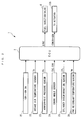
- FIG. 1 schematically shows an internal combustion engine 3 to which is applied a stop control system 1 (see FIG. 2 ) according to the present embodiment.
- This internal combustion engine (hereinafter referred to as the "engine") 3 is a six-cylinder gasoline engine, for example.
- Fuel injection valves 6 are mounted on respective cylinders 3a of the engine 3. The opening and closing of each fuel injection valve 6 is controlled by a control signal from an ECU 2 (see FIG. 2 ), whereby fuel injection timing is controlled by valve-opening timing of the fuel injection valve 6, and a fuel injection amount QINJ is controlled by a valve-opening time period thereof.
- Cylinder heads 3b of respective cylinders 3a of the engine 3 are connected to an intake pipe 4 and an exhaust pipe 5, cylinder by cylinder, and a pair of intake valves 8 and 8 (only one of which is shown) and a pair of exhaust valves 9 and 9 (only one of which is shown) are provide for each cylinder head 3b.
- the cylinder head 3b is provided therein with a rotatable intake cam shaft 41, an intake cam 42 integrally formed with the intake cam shaft 41, a rocker arm shaft 43, and two rocker arms 44 and 44 (only one of which is shown) which are pivotally supported by the rocker arm shaft 43 for being brought into abutment with respective top ends of the intake valves 8 and 8.
- the intake cam shaft 41 is connected to a crankshaft 3c (see FIG. 1 ) via an intake sprocket and a timing chain (neither of which is shown), and rotates once whenever the crankshaft 3c rotates twice.
- the rocker arms 44 and 44 are pressed by the intake cam 42 to be pivotally moved about the rocker arm shaft 43, whereby the intake valves 8 and 8 are opened and closed.
- the cylinder head 3b is provided therein with a rotatable exhaust cam shaft 61, an exhaust cam 62 integrally formed with the exhaust cam shaft 61, a rocker arm shaft 63, and two rocker arms 64 and 64 (only one of which is shown) which are pivotally supported by the rocker arm shaft 63 for being brought into abutment with respective top ends of the exhaust valves 9 and 9.
- the exhaust cam shaft 61 is connected to the crankshaft 3c via an exhaust sprocket and a timing chain (neither of which is shown), and rotates once whenever the crankshaft 3c rotates twice.
- the rocker arms 64 and 64 are pressed by the exhaust cam 62 to be pivotally moved about the rocker arm shaft 63, whereby the exhaust valves 9 and 9 are opened and closed.
- the intake cam shaft 41 is provided with a cylinder discrimination sensor 25.
- the cylinder discrimination sensor 25 delivers a CYL signal, which is a pulse signal, to the ECU 2 at a predetermined crank angle position of a specific cylinder 3a.
- the crankshaft 3c is provided with a crank angle sensor 24.
- the crank angle sensor 24 delivers a TDC signal and a CRK signal, which are both pulse signals, to the ECU 2 along with rotation of the crankshaft 3c.
- the TDC signal indicates that a piston 3d of one of the cylinders 3a is at a predetermined crank angle position in the vicinity of the top dead center (TDC) at the start of the intake stroke thereof, and in the case of the six-cylinder engine as in the present embodiment, it is delivered whenever the crankshaft 3c rotates through 120 ° .
- the CRK signal is delivered whenever the crankshaft 3c rotates through a predetermined angle (e.g.
- the ECU 2 calculates the rotational speed of the engine 3 (hereinafter referred to as "the engine speed") NE based on the CRK signal.
- This engine speed NE represents the rotational speed of the engine 3.
- the ECU 2 determines which cylinders 3a is in the compression stroke, based on the CYL signal and the TDC signal, and assigns cylinder numbers CUCYL 1 to 6 to the respective cylinders 3a, based on results of the determination.
- the ECU 2 calculates a crank angle CA based on the TDC signal and the CRK signal, and sets a stage number STG. Assuming that a reference angle position of the crank angle CA, which corresponds to a start of the intake stroke in one of the cylinders 3a, is set to 0 ° , the stage number STG is set to 0 when the crank angle CA is within a range of 0 ⁇ CA ⁇ 30, to 1 when the same is within a range of 30 ⁇ CA ⁇ 60, to 2 when the same is within a range of 60 ⁇ CA ⁇ 90, and to 3 when the same is within a range of 90 ⁇ CA ⁇ 120.
- the intake pipe 4 is provided with a throttle valve mechanism 13.
- the throttle valve mechanism 13 has a throttle valve 13a which is pivotally provided in the intake pipe 4 and a TH actuator 13b for actuating the throttle valve 13a.
- the TH actuator 13b is a combination of a motor and a gear mechanism (neither of which is shown), and is driven by a control signal based on a target opening degree ICMDTHIGOF delivered from the ECU 2. This varies the opening degree of the throttle valve 13a, whereby the amount of fresh air drawn into each cylinder 3a (hereinafter referred to as the "fresh air amount”) is controlled.
- an intake air temperature sensor 22 is disposed in the intake pipe 4 at a location downstream of the throttle valve 13a.
- the intake air temperature sensor 22 detects the temperature of intake air (hereinafter referred to as the "intake air temperature") TA, and delivers a detection signal indicative of the detected intake air temperature TA to the ECU 2.
- a detection signal indicative of atmospheric pressure PA from an atmospheric pressure sensor 23 and a detection signal indicative of the temperature of engine coolant of the engine 3 (hereinafter referred to as "the engine coolant temperature”) TW from an engine coolant temperature sensor 26.
- a signal indicative of an on/off state of an ignition switch (SW) 21 (see FIG. 2 ) is delivered from the ignition switch 21 to the ECU 2. Note that during stoppage of the engine 3, when the ignition switch 21 is turned off, supply of fuel from the fuel injection valve 6 to the cylinders 3a is stopped.
- the ECU 2 is implemented by a microcomputer comprising an I/O interface, a CPU, a RAM, and a ROM (none of which are specifically shown).
- the detection signals from the aforementioned switch and sensors 21 to 26 are input to the CPU after the I/O interface performs A/D conversion and waveform shaping thereon.
- the ECU 2 determines operating conditions of the engine 3 in accordance with control programs stored in the ROM, and executes control of the engine 3 including stop control, based on the determined operating conditions.
- the ECU 2 corresponds to rotational speed-detecting means, first intake air amount control means, second intake air amount control means, second predetermined rotational speed-setting means, first predetermined rotational speed-setting means, second predetermined opening degree-setting means, first predetermined rotational speed-limiting means, first predetermined opening degree-correcting means, first predetermined opening degree-setting means, first correction means, and second correction means.
- the stop control is for controlling the stop position of the piston 3d to a predetermined position at which no valve overlap occurs in which the intake valve 8 and the exhaust valve 9 open at the same time, by controlling the throttle valve 13a toward an open side when the engine speed NE becomes lower than a stop control start rotational speed NEIGOFTH after the ignition switch 21 has been turned off, to thereby control the engine speed NE in the final compression stroke immediately before stoppage of the piston 3d (final compression stroke rotational speed NEPRSFTGT) to a predetermined reference value.
- FIG. 4 shows a process for setting a target stop control start rotational speed NEICOFREFX.
- the present process and processes described hereinafter are executed in synchronism with generation of the CYL signal.
- the present process is for setting a target value of the stop control start rotational speed for starting control of the throttle valve 13a toward the open side in the stop control (second stage control, described hereinafter) as a target stop control start rotational speed NEICOFREFX, and for learning the target value.
- the present process is carried out once in a single stop control process.
- step 1 it is determined whether or not a target stop control start rotational speed setting completion flag F_IGOFTHREFDONE is equal to 1. If the answer to this question is affirmative (YES), i.e. if the target stop control start rotational speed NEICOFREFX has already been set, the present process is immediately terminated.
- step 2 it is determined whether or not the number of times of learning NENGSTP is equal to 0. If the answer to this question is affirmative (YES), i.e. if the number of times of learning NENGSTP has been reset e.g. by battery cancellation, the target stop control start rotational speed NEICOFREFX is set to a predetermined initial value NEICOFINI (step 3), and then the process proceeds to a step 12, referred to hereinafter.
- a learning condition satisfied flag F_NEICOFRCND is set to 1 when there are satisfied predetermined learning conditions for learning the target stop control start rotational speed NEICOFREFX, including a condition that no engine stall is caused and a condition that the engine coolant temperature TW is not in a low temperature state where it is not higher than a predetermined value. If the answer to the question of the step 4 is negative (NO), i.e. if the learning conditions are not satisfied, the target stop control start rotational speed NEICOFREFX is not learned, but the process proceeds to a step 13, referred to hereinafter.
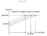
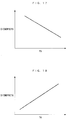
- This equation (1) is based on preconditions that a correlation as shown in FIG. 9 , i.e. a correlation expressed by a linear function having a slope of SLOPENPF0 and an intercept of INTCPNPF holds between the stop control start rotational speed NEIGOFTH and the final compression stroke rotational speed NEPRSFTGT, and the slope SLOPENPF0 is constant if the engine 3 is of the same type.
- the intercept INTCPNPF is calculated according to the above preconditions, using the stop control start rotational speed NEIGOFTH obtained during the stop control and the final compression stroke rotational speed NEPRSTGT, by the equation (1).
- a basic value NEICOFRRT of the target stop control start rotational speed is calculated based on the correlation determined as described above, by using the calculated intercept INTCPNPF and slope SLOPENPF0 and applying a predetermined reference value NENPFLMT0 of the final compression stroke rotational speed to the following equation (2) (see FIG. 9 ).
- NEICOFRRT NENPFLMT ⁇ 0 - INTCPNPF - SLOPENPF ⁇ 0
- the reference value NENPFLMT0 of the final compression stroke rotational speed corresponds to such a value that will cause the piston 3d to stop at a predetermined position free from occurrence of valve overlap, when the final compression stroke rotational speed NEPRSF is controlled to the reference value NENPFLMT0.
- the reference value NENPFLMT0 is determined empirically e.g. by experiment in advance, and is set to e.g. 260 rpm in the present embodiment. Therefore, by using the basic value NEICOFRRT of the target stop control start rotational speed calculated by the above-mentioned equation (2), it is possible to stop the piston 3d at the predetermined position.
- a map shown in FIG. 10 is searched according to the atmospheric pressure PAO detected during the stop control to determine a map value DNEICOFPA, and the map value DNEICOFPA is set as a learning PA correction term dneicofrpa.
- a map shown in FIG. 11 is searched according to an intake air temperature TAO detected during the stop control to determine a map value DNEICOFTA, and the map value DNEICOFTA is set as a learning TA correction term dneicofrta.
- a corrected basic value NEICOFREF of the target stop control start rotational speed is calculated using the basic value NEICOFRRT of the target stop control start rotational speed, the learning PA correction term dneicofrpa, and the learning TA correction term dneicofrta calculated in the steps 6 to 8, by the following equation (3) (step 9) :
- NEICOFREF NEICOFRRT - dneicofrpa - dneicofrta
- the learning PA correction term dneicofrpa is set to a larger value as the atmospheric pressure PAO is higher, the corrected basic value NEICOFREF of the target stop control start rotational speed is corrected to a smaller value as the atmospheric pressure PAO is higher. Further, since the learning TA correction term dneicofrta set to a larger value as the intake air temperature TA0 is lower, the corrected basic value NEICOFREF of the target stop control start rotational speed is corrected to a smaller value as the intake air temperature TAO is lower.
- an averaging coefficient CICOFREFX is calculated by searching a map shown in FIG. 12 according to the number of times of learning NENGSTP.
- the averaging coefficient CICOFREFX is set to a larger value as the number of times of learning NENGSTP is larger (0 ⁇ CICOFREFX ⁇ 1).
- a current value NEICOFREFX of the target stop control start rotational speed is calculated using the calculated corrected basic value NEICOFREF of the target stop control start rotational speed, an immediately preceding value NEICOFREFX of the target stop control start rotational speed, and the averaging coefficient CICOFREFX, by the following equation (4):
- NEICOFREFX NEICOFREF ⁇ 1 - CICOFREFX + NEICOFREFX ⁇ CICOFREFX
- the target stop control start rotational speed NEICOFREFX is calculated as a weighted average value of the corrected basic value NEICOFREF of the target stop control start rotational speed and the immediately preceding value NEICOFREFX of the target stop control start rotational speed, and the averaging coefficient CICOFREFX is used as a weight coefficient for weighted averaging.
- the current value NEICOFREFX of the target stop control start rotational speed is calculated such that it becomes closer to the corrected basic value NEICOFREF of the target stop control start rotational speed as the averaging coefficient CICOFREFX is smaller, whereas it becomes closer to the immediately preceding value NEICOFREFX of the target stop control start rotational speed as the averaging coefficient CICOFREFX is larger.
- the averaging coefficient CICOFREFX is set as described above according to the number of times of learning NENGSTP, and therefore as the number of times of learning NENGSTP is smaller, the degree of reflection of the corrected basic value NEICOFREF of the target stop control start rotational speed becomes larger, whereas as the number of times of learning NENGSTP is larger, the degree of reflection of the immediately preceding value NEICOFREFX of the target stop control start rotational speed becomes larger.
- step 12 following the step 3 or 11, the number of times of learning NENGSTP is incremented. Further, if the answer to the question of the step 4 is negative (NO), or after the step 12, the proceeds to the step 13, wherein in order to indicate that the setting of the target stop control start rotational speed NEICOFREFX has been completed, the target stop control start rotational speed setting completion flag F_IGOFTHREFDONE is set to 1, followed by terminating the present process.
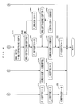
- FIGS. 5 and 6 show a process for setting a target opening degree ICMDTHIGOF that serves as a target of the opening degree of the throttle valve 13a.
- fully-closing control for controlling the target opening degree ICMDTHIGOF of the throttle valve 13a to 0
- first stage control for setting the target opening degree ICMDTHIGOF to a first predetermined opening degree
- second stage control for setting the target opening degree ICMDTHIGOF to a second predetermined opening degree larger than the first predetermined opening degree are performed in the mentioned order according to the engine speed NE.
- a second stage control execution flag F_IGOFFTH2 is set to 1 during execution of the above-described second stage control, and otherwise set to 0. If the answer to the question of the step 21 is affirmative (YES), the present process is immediately terminated.
- a fuel cut flag F_IGOFFFC is equal to 1. If the answer to this question is negative (NO), i.e. if interruption of fuel supply to the engine 3 has not been completed yet after turning off the ignition switch 21, a first stage control execution flag F_IGOFFTH1 and the second stage control execution flag F_IGOFFTH2 are set to 0 (steps 23 and 24), respectively, and the target opening degree ICMDTHIGOF is set to 0 (step 25), followed by terminating the present process.
- step 22 if the answer to the question of the step 22 is affirmative (YES), i.e. if the interruption of fuel supply to the engine 3 has been completed, the above-mentioned map shown in FIG. 10 is searched according to the atmospheric pressure PA currently detected to thereby determine the map value DNEICOFPA, and the map value DNEICOFPA is set as a setting PA correction term dneicofpax (step 26).
- a step 27 the above-mentioned map shown in FIG. 11 is searched according to the intake air temperature TA currently detected to thereby determine the map value DNEICOFTA, and the map value DNEICOFTA is set as a setting TA correction term dneicoftax.
- a corrected target stop control start rotational speed NEICOFREFN is calculated using the target stop control start rotational speed NEICOFREFX set in the step 11 in FIG. 4 , the setting PA correction term dneicofpax, and the setting TA correction term dneicoftax calculated as described above, by the following equation (5):
- NEICOFREFN NEICOFREFX + dneicofpax + dneicoftax
- the corrected target stop control start rotational speed NEICOFREFN is corrected to a larger value as the atmospheric pressure PA is higher. This is for the following reason:
- the corrected target stop control start rotational speed NEICOFREFN is corrected to a larger value as the intake air temperature TA is lower.
- the sliding friction of the piston 3d is larger and the density of intake air is higher, which increases the rate of reduction of the engine speed NE. Therefore, by correcting the corrected target stop control start rotational speed NEICOFREFN to a larger value as the intake air temperature TA is lower and starting the second stage control in earlier timing, it is possible to properly avoid the adverse influence of the operation of the throttle valve 13a and the delay of intake air.
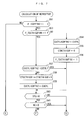
- FIG. 13 shows a subroutine of a process for calculating the first stage control target opening degree ICMDOFPRE.
- This upper limit value NEPRELMT corresponds to a value at which the engine 3 might resonate if the first stage control is started in a state where the engine speed NE is higher than the upper limit value NEPRELMT, and is set to 600 rpm, for example.
- the first stage control target opening degree ICMDOFPRE is set to a predetermined basic value ICMDPREB (step 73), followed by terminating the present process.
- the first stage control start rotational speed NEICOFPRE is set to the upper limit value NEPRELMT, for limitation (step 74). Further, the first stage control target opening degree ICMDOFPRE is set to a value obtained by adding a predetermined correction term DICMD to the basic value ICMDPREB (step 75), followed by terminating the present process.
- step 30 it is determined whether or not the engine speed NE is smaller than the calculated first stage control start rotational speed NEICOFPRE. If the answer to this question is negative (NO), i.e. if NE ⁇ NEICOFPRE holds, the above-described steps 23 to 25 are executed to thereby continue the full closing control of the throttle valve 13a, followed by terminating the present process.
- step 31 it is determined whether or not the first stage control execution flag F_IGOFFTH1 is equal to 1 (step 31). If the answer to this question is negative (NO), i.e. if the first stage control has not been executed yet, the target opening degree ICMDTHIGOF is set to the first stage control target opening degree ICMDOFPRE calculated in the step 29 (step 34), and the first stage control of the throttle valve 13a is started. Further, to indicate that the first stage control is being executed, the first stage control execution flag F_IGOFFTH1 is set to 1 (step 35), followed by terminating the present process.
- step 31 determines whether or not the stage number STG is 0 (step 32). If the answer to this question is negative (NO), i.e. if none of the cylinders 3a are in the middle stage of the compression stroke, the above-described steps 34 and 35 are executed, followed by terminating the present process.
- step 32 determines whether or not the engine speed NE is smaller than the corrected target stop control start rotational speed NEICOFREFN calculated in the step 28 (step 33). If the answer to this question is negative (NO), i.e. if NEICOFREFN ⁇ NE ⁇ NEICOFPRE holds, the above-described steps 34 and 35 are executed to thereby continue the first stage control, followed by terminating the present process.
- step 33 determines whether the answer to the question of the step 33 is affirmative (YES), i.e. if the stage number STG is 0, and at the same time if the engine speed NE is lower than the corrected target stop control start rotational speed NEICOFREFN.
- the process proceeds to a step 36, wherein the engine speed NE obtained at the time is stored as an actual stop control start rotational speed NEIGOFTH, and the atmospheric pressure PA and intake air temperature TA currently detected are stored as the atmospheric pressure PA0 and intake air temperature TA0 detected during the stop control, respectively, (steps 37 and 38).
- the stored stop control start rotational speed NEIGOFTH is used in the aforementioned equation (1), and the atmospheric pressure PAO and the intake air temperature TA0 are used in the steps 7 and 8 in FIG. 4 for calculating the learning PA correction term dneicofrpa and the learning TA correction term dneicofrta, respectively.
- a rotational speed difference flag F_DNEIGOFTH is set to 0 (step 41), and the target opening degree ICMDTHIGOF is set to the second predetermined opening degree ICMDOF2 for use in the second stage control (step 42).
- This second predetermined opening degree ICMDOF2 is larger than the first stage control target opening degree ICMDOFPRE for use in the first stage control.
- the second stage control execution flag F_IGOFFTH2 is set to 1 (step 43), followed by terminating the present process.
- the rotational speed difference flag F_DNEIGOFTH is set to 1 (step 44). Then, it is determined whether or not the difference DNEIGOFTH is not smaller than a predetermined second reference value DNEIGOFTHH which is larger than the first reference value DNEIGOFTHL (step 45). If the answer to this question is affirmative (YES), i.e.
- step 42 the target opening degree ICMDTHIGOF is set to the second predetermined opening degree ICMDOF2, and the above-mentioned step 43 is executed, followed by terminating the present process.
- the target opening degree ICMDTHIGOF is set to a third predetermined opening degree ICMDOF3 (step 46), and the step 43 is executed, followed by terminating the present process.
- This third predetermined opening degree ICMDOF3 is larger than the first stage control target opening degree ICMDOFPRE, and is smaller than the second predetermined opening degree ICMDOF2.
- FIGS. 7 and 8 show a process for calculating the final compression stroke rotational speed NEPRSFTGT.
- the present process first, in a step 51, it is determined whether or not the second stage control execution flag F_IGOFFTH2 is equal to 1. If the answer to this question is negative (NO), i.e. if the second stage control is not being executed, the final compression stroke rotational speed NEPRSFTGT is set to 0 (step 52), followed by terminating the present process.
- step 53 it is determined in a step 53 whether or not an initialization completion flag F_TDCTHIGOFINI is equal to 1. If the answer to this question is negative (NO), the cylinder number CUCYL assigned at the time is shifted to an immediately preceding value CUCYLIGOFTHZ thereof (step 54). Further, a TDC counter value CTDCTHIGOF for measuring the number of times of occurrence of TDC after the start of the second stage control is reset to 0 (step 55), and to indicate that the above-mentioned initialization has been completed, the initialization completion flag F_TDCTHIGOFINI is set to 1 (step 56). Then, the process proceeds to a step 60, described hereinafter.
- step 53 determines whether or not the immediately preceding value CUCYLIGOFTHZ of the cylinder number and the cylinder number CUCYL assigned at the time are equal to each other (step 57). If the answer to this question is affirmative (YES), the process proceeds to the step 60, described hereinafter.
- step 57 if the answer to the question of the step 57 is negative (NO), i.e. if CUCYLIGOFTHZ ⁇ CUCYL holds, it is determined that TDC has occurred, and the TDC counter value CTDCTHIGOF is incremented (step 58). Then, the cylinder number CUCYL assigned at the time is shifted to the immediately preceding value CUCYLIGOFTHZ thereof (step 59), and then the process proceeds to the step 60.
- step 60 it is determined whether or not the stage number STG is 0, and in a step 61, it is determined whether or not the engine speed NE is equal to 0. If the answer to the question of the step 60 is negative (NO), i.e. if none of the cylinders 3a are in the middle stage of the compression stroke, or if the answer to the question of the step 61 is affirmative (YES), i.e. if the engine 3 has been completely stopped, the present process is terminated.
- step 60 determines whether or not a provisional value NEPRSF of the final compression stroke rotational speed is larger than the engine speed NE obtained at the time. If the answer to this question is negative (NO), i.e. if NEPRSF ⁇ NE holds, the present process is terminated.
- step 62 if the answer to the question of the step 62 is affirmative (YES), i.e. if NEPRSF > NE holds, the engine speed NE is stored as the provisional value NEPRSF of the final compression stroke rotational speed (step 63), and then it is determined in a step 64 whether or not a final compression stroke rotational speed calculation completion flag F_SETPRSFTGT is equal to 1. If the answer to this question is affirmative (YES), i.e. if calculation of the final compression stroke rotational speed NEPRSFTGT has already been completed, the present process is terminated.
- the TDC counter value CTDCTHIGOF is equal to a predetermined value NTDCIGOFTH (STEP 65).
- This predetermined value NTDCIGOFTH is determined in advance by determining empirically e.g. by experiment how many times of occurrence of TDC after the start of the second stage control will bring about the final compression stroke, and is set to e.g. 3 in the present embodiment.
- step 65 If the answer to the question of the step 65 is negative (NO), it is judged that the final compression stroke has not been reached, and hence the process proceeds to the step 52, wherein the final compression stroke rotational speed NEPRSFTGT is set to 0, followed by terminating the present process.
- the final compression stroke rotational speed NEPRSFTGT is calculated as the final compression stroke rotational speed NEPRSFTGT (step 66). Further, the final compression stroke rotational speed calculation completion flag F_SETPRSFTGT is set to 1 (step 67), followed by terminating the present process.
- the final compression stroke rotational speed NEPRSFTGT thus calculated is applied to the aforementioned equation (1), and is used for setting the target stop control start rotational speed NEICOFREFX.
- FIG. 14 shows an example of an operation obtained by a stop control process of the engine 3 according to the above-described first embodiment.
- the ignition switch (SW) 21 when the ignition switch (SW) 21 is turned off, the supply of fuel from the fuel injection valve 6 is stopped, whereby the engine speed NE is lowered. Further, at this time, the target opening degree ICMDTHIGOF is set to 0, whereby the opening degree of the throttle valve 13a (throttle valve opening ATH) is controlled such that the throttle valve 13a is fully closed, and in accordance therewith, the intake pressure PBA is reduced.
- SW ignition switch
- the first stage control is started, and the target opening degree ICMDTHIGOF is set to the first stage control target opening degree ICMDOFPRE, whereby the throttle valve opening ATH is controlled toward the open side, and in accordance therewith, the intake pressure PBA increases.
- the first stage control is terminated, and the second stage control is started.
- the intake pressure PBA has increased up to a desired initial value PBAREF.
- the target opening degree ICMDTHIGOF is set to the second predetermined opening degree ICMDOF2, whereby the throttle valve opening ATH becomes larger.
- the intake pressure PBA increases from the initial value PBAREF to the atmospheric pressure PA.
- the final compression stroke rotational speed NEPRSFTGT becomes approximately equal to the reference value NENPFLMT0, whereby it is possible to accurately stop the piston 3d at the predetermined position to prevent valve overlap.
- the corrected target stop control start rotational speed NEICOFREFN is set to a smaller value than in the above-described case indicated by solid lines, and accordingly the first stage control start rotational speed NEICOFPRE is set to a smaller value (step 71 in FIG. 13 ).
- This causes the second stage control to be started in later timing than in the above-described case indicated by solid lines, and in accordance with, the first stage control is also started in later timing.
- the intake pressure PBA at the start of the second stage control is approximately equal to the desired initial value PBAREF. Therefore, similarly to the case indicated by solid lines, it is possible to accurately stop the piston 3d at the predetermined position.
- the corrected target stop control start rotational speed NEICOFREFN is set to a larger value than in the above-described case indicated by solid lines, and accordingly, inversely to the case indicated by broken lines, the first stage control start rotational speed NEICOFPRE is set to a larger value (step 71 in FIG. 13 ).
- This causes the second stage control to be started in earlier timing than in the case indicated by the solid lines, and in accordance therewith, the first stage control is also started in earlier timing.
- the intake pressure PBA at the start of the second stage control is approximately equal to the desired initial value PBAREF. Therefore, similarly to the case indicated by solid lines, it is possible to accurately stop the piston 3d at the predetermined position.
- the target opening degree ICMDTHIGOF of the throttle valve 13a is set to the first stage control target opening degree ICMDOFPRE by the first stage control (step 34 in FIG. 6 ), and then is set to the second predetermined opening degree ICMDOF2 or the third predetermined opening degree ICMDOF3, larger than the first stage control target opening degree ICMDOFPRE, by the second stage control (steps 42 and 46 in FIG. 6 ).
- the throttle valve 13a by opening the throttle valve 13a in two stages, it is possible to avoid a steep rise in the intake pressure PBA during opening the throttle valve 13a, thereby making it possible to prevent occurrence of untoward noise, such as flow noise, and vibration caused by the steep increase in the intake pressure PBA.
- the target opening degree ICMDTHIGOF of the throttle valve 13a is not progressively increased but is held at the first stage control target opening degree ICMDOFPRE, and hence it is possible to stabilize initial conditions, such as the intake pressure PBA, at the start of the second stage control, while suppressing adverse influences of variation in the operating characteristics of the throttle valve 13a and delay in operation. This makes it possible to accurately stop the piston 3d at the predetermined position by the second stage control.
- the first stage control start rotational speed ICMDOFPRE is set to a value obtained by adding the predetermined value DNEICOFPRE to the changed corrected target stop control start rotational speed NEICOFREFN (step 71 in FIG. 13 ). Therefore, even when timing for starting the second stage control is changed, the first stage control is started in timing coping with the change in the start timing, whereby it is possible to stabilize the initial conditions for the second stage control, thereby making it possible to ensure the accuracy of the stop control of the piston 3d by the second stage control.
- the first stage control start rotational speed ICMDOFPRE set according to the corrected target stop control start rotational speed NEICOFREFN is larger than the upper limit value NEPRELMT
- the first stage control start rotational speed ICMDOFPRE is limited to the upper limit value NEPRELMT (steps 72 and 74 in FIG. 13 ). This causes the first stage control to be started after waiting for the engine speed NE to be lowered to the upper limit value NEPRELMT, so that it is possible to avoid execution of the first stage control in a resonance area where the engine speed NE is high, thereby making it possible to positively prevent untoward noise and vibration caused by the resonance of the engine 3.
- the first stage control target opening degree ICMDOFPRE is corrected to a larger value (step 75 in FIG. 13 ), so that by compensating for the insufficient amount of the intake air amount due to delay of start of the first stage control, it is possible to stabilize the initial conditions for the second stage control, thereby making it possible to ensure the accuracy of the stop control of the piston 3d.
- target stop control start rotational speed NEICOFREFX is corrected according to the actual atmospheric pressure PA and intake air temperature TA to calculate the corrected target stop control start rotational speed NEICOFREFN (steps 26 to 28 in FIG. 5 ), it is possible to more properly set the corrected target stop control start rotational speed NEICOFREFN, thereby making it possible to further enhance the accuracy of the stop control of the piston 3d.
- the first stage control start rotational speed NEICOFPRE is calculated by adding the predetermined value DNEICOFPRE to the corrected target stop control start rotational speed NEICOFREFN, this value may be further corrected by the atmospheric pressure PA and the intake air temperature TA.
- the aforementioned map shown in FIG. 10 is searched according to the atmospheric pressure PA to determine the map value DNEICOFPA, and the map value DNEICOFPA is set as a setting PA correction term dneicofpax1. Further, the aforementioned map shown in FIG.
- NEICOFPRE NEICOFREFN + DNEICOFPRE + dneicofpax ⁇ 1 + dneicoftax ⁇ 1
- the above-mentioned setting PA correction term dneicofpax1 is set to a larger value as the atmospheric pressure PA is higher, and the setting TA correction term dneicoftax1 is set to a larger value as the intake air temperature TA is lower.
- the first stage control start rotational speed NEICOFPRE is corrected such that it becomes larger as the atmospheric pressure PA is higher and as the intake air temperature TA is lower. This makes it possible to set the first stage control start rotational speed NEICOFPRE in a more fine-grained manner according to the actual atmospheric pressure PA and intake air temperature TA, to more properly control an intake pressure PBA at the start of the second stage control, and therefore it is possible to further enhance the accuracy of the stop control of the piston 3d.
- the second predetermined opening degree ICMDOF2 is a fixed value
- the second predetermined opening degree ICMDOF2 may be corrected and set using the atmospheric pressure PA and the intake air temperature TA.
- a map shown in FIG. 22 is searched according to the atmospheric pressure PA to determine a map value DATHICOFPA, whereby the map value DATHICOFPA is set as a setting PA correction term dathicofpax
- a map shown in FIG. 23 is searched according to the intake air temperature TA to determine a map value DATHICOFTA, whereby the map value DATHICOFTA is set as a setting TA correction term dathicoftax.
- the second predetermined opening degree ICMDOF2 is calculated using a basic value ICMDOF2B of the second predetermined opening degree and the setting PA correction term dathicofpax and the setting TA correction term dathicoftax, by the following equation (7) :
- ICMDOF ⁇ 2 ICMDOF ⁇ 2 ⁇ B + dathicofpax + dathicoftax
- the map value DATHICOFPA is set to a larger value as the atmospheric pressure PA is lower, and in the map shown in FIG. 23 , the map value DATHICOFTA is set to a larger value as the intake air temperature TA is higher.
- the second predetermined opening degree ICMDOF2 is corrected such that it becomes larger as the atmospheric pressure PA is lower and as the intake air temperature TA is higher. This makes it possible to set the second predetermined opening degree ICMDOF2 in a more fine-grained manner according to the actual atmospheric pressure PA and intake air temperature TA, and therefore it is possible to further enhance the accuracy of the stop control of the piston 3d.
- the first stage control target opening degree ICMDOFPRE is changed according to a change in the corrected target stop control start rotational speed NEICOFREFN.
- the first stage control target opening degree ICMDOFPRE is changed without changing the first stage control start rotational speed NEICOFPRE.
- a step 81 the difference between the predetermined first stage control start rotational speed NEICOFPRE and the corrected target stop control start rotational speed NEICOFREFN calculated in the step 28 in FIG. 5 is calculated as a rotational speed difference DNE12.
- an NE correction term DICMDPRENE is calculated by searching a map shown in FIG. 16 according to the calculated rotational speed difference DNE12 (step 82).
- the NE correction term DICMDPRENE is set to a larger value as the rotational speed difference DNE12 is smaller.
- a PA correction term DICMDPREPA is calculated by searching a map shown in FIG. 17 according to the atmospheric pressure PA (step 83).
- the PA correction term DICMDPREPA is set to a larger value as the atmospheric pressure PA is lower.
- a TA correction term DICMDPRETA is calculated by searching a map shown in FIG. 18 according to the intake air temperature TA (step 84).
- the TA correction term DICMDPRETA is set to a larger value as the intake air temperature TA is higher.
- the first stage control target opening degree ICMDOFPRE is calculated by adding the NE correction term DICMDPRENE, the PA correction term DICMDPREPA, and the TA correction term DICMDPRETA, which are calculated in the steps 82 to 84, to a predetermined basic value ICMDPREB (step 85), by the following equation (8), followed by terminating the present process.
- ICMDOFPRE ICMDPREB + DICMDPRENE + DICMDPREPA + DICMDPRETA
- the PA correction term DICMDPREPA is set to a larger value to increase the intake air amount and the intake pressure PBA, whereby it is possible to hold the intake pressure PBA at the start of the second stage control substantially constant.
- the TA correction term DICMDPRETA is set to a larger value to increase the intake air amount and the intake pressure PBA, whereby it is possible to hold the intake pressure PBA at the start of the second stage control substantially constant.
- FIG. 19 shows an example of an operation obtained by a stop control process of the engine 3 according to the above-described second embodiment.
- the target opening degree ICMDTHIGOF is set to 0, whereby the throttle valve opening ATH is controlled such that the throttle valve 13a is fully closed, and the intake pressure PBA is reduced.
- the first stage control is started, and further when the engine speed NE becomes lower than the corrected target stop control start rotational speed NEICOFREFN, the second stage control is started.
- the intake pressure PBA has increased up to the desired initial value PBAREF.
- the corrected target stop control start rotational speed NEICOFREFN is set to a smaller value than in the above-described case indicated by solid lines, and in accordance therewith, the first stage control target opening degree ICMDOFPRE is set to a smaller value (step 82 in FIG. 15 ).
- the second control is started in later timing than in the case indicated by solid lines, and accordingly makes the time period for the first stage control longer while reducing the intake air amount.
- the intake pressure PBA at the start of the second stage control is approximately equal to the initial value PBAREF.
- the corrected target stop control start rotational speed NEICOFREFN is set to a larger value than in the above-described case indicated by solid lines, and accordingly, the first stage control target opening degree ICMDOFPRE is set to a larger value (step 82 in FIG. 15 ).
- This causes the second control to be started in earlier timing than in the case indicated by solid lines, and accordingly, makes the time period for the first stage control shorter while reducing the intake air amount.
- the intake pressure PBA at the start of the second stage control is approximately equal to the initial value PBAREF.
- the first stage control target opening degree ICMDOFPRE is set according to the rotational speed difference DNE12 between the predetermined first stage control start rotational speed NEICOFPRE and the changed corrected target stop control start rotational speed NEICOFREFN such that it is set to a larger value as the rotational speed difference DNE12 is smaller ( FIG. 15 steps 81 and 82, FIG. 16 ).
- the first stage control is executed by the intake air amount coping with the change in the timing, whereby it is possible to stabilize the initial conditions for the second stage control, thereby making it possible to ensure the accuracy of the stop control of the piston 3d by the second stage control.
- the first stage control target opening degree ICMDOFPRE is corrected according to the actual atmospheric pressure PA and intake air temperature TA (steps 83 to 85 in FIG. 15 ), it is possible to more properly set the first stage control target opening degree ICMDOFPRE, and therefore it is possible to further stabilize the initial conditions for the second stage control, thereby making it possible to further enhance the accuracy of the stop control of the piston 3d.
- the target stop control start rotational speed NEICOFREFX which is a target value of the stop control start rotational speed for starting the second stage control
- a target second stage control opening degree ATHICOFREFX in the second stage control is set and learned.
- FIG. 20 shows a process for setting this target second stage control opening degree ATHICOFREFX.
- a target second stage control opening degree-setting completion flag F_IGOFATHREFDONE is equal to 1. If the answer to this question is affirmative (YES), i.e. if the target second stage control opening degree ATHICOFREFX has already been set, the present process is immediately terminated.
- step 91 determines whether or not the number of times of learning NENGSTP is equal to 0. If the answer to this question is affirmative (YES), the target second stage control opening degree ATHICOFREFX is set to a predetermined initial value ATHICOFINI (step 93), and then the process proceeds to a step 102, described hereinafter.
- step 94 it is determined in a step 94 whether or not the aforementioned learning condition satisfied flag F_NEICOFRCND is equal to 1. If the answer to this question is negative (NO), i.e. if the learning conditions are not satisfied, the target second stage control opening degree NEICOFREFX is not learned, and then the process proceeds to a step 103, described hereinafter.
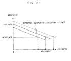
- This equation (9) is based on preconditions that a correlation as shown in FIG. 21 , i.e. a correlation expressed by a linear function having a slope of SLOPENTF0 and an intercept of INTCPNTF holds between the second stage control opening degree ATHIGOFTH and the final compression stroke rotational speed NEPRSFTGT, and the slope SLOPENTF0 is constant if the engine 3 is of the same type.
- the intercept INTCPNTF is calculated according to the above preconditions, using the second stage control opening degree ATHIGOFTH and the final compression stroke rotational speed NEPRSTGT obtained during the stop control, by the equation (9), whereby the correlation between the second stage control opening degree ATHIGOFTH and the final compression stroke rotational speed NEPRSFTGT is determined.
- the final compression stroke rotational speed NEPRSTGT takes a larger value with respect to a basic value ATHICOFRRT of the same target second stage control opening degree, so that the linear function is offset toward an upper side (as indicated by broken lines in FIG. 21 , for example), and the intercept INTCPNTF is calculated to be a larger value.
- the linear function is offset toward a lower side (as indicated by one-dot chain lines in FIG. 21 , for example) for the converse reason to the above, and the intercept INTCPNTF is calculated to be a smaller value.
- ATHICOFRRT NENPFLMT ⁇ 0 - INTCPNPF / SLOPENTF ⁇ 0
- a map shown in FIG. 22 is searched according to the atmospheric pressure PAO detected during the stop control to determine the map value DATHICOFPA, and the map value DATHICOFPA is set as the learning PA correction term dathicofrpa.
- a map shown in FIG. 23 is searched according to the intake air temperature TAO detected during the stop control to determine a map value DATHICOFTA, and the map value DATHICOFTA is set as a learning TA correction term dathicofrta.
- the above-described learning PA correction term dathicofrpa is set to a smaller value as the atmospheric pressure PAO is higher, and the learning TA correction term dathicofrta is set to a smaller value as the intake air temperature TA0 is lower.
- a corrected basic value ATHICOFREF of the target second stage control opening degree is calculated using the basic value ATHICOFRRT of the target second stage control opening degree, the learning PA correction term dathicofrpa, and the learning TA correction term dathicofrta, which are calculated in the steps 96 to 98, by the following equation (11) (step 99):
- ATHICOFREF ATHICOFRRT - dathicofrpa - dathicofrta
- the learning PA correction term dathicofrpa is set to a smaller value as the atmospheric pressure PAO is higher, the corrected basic value ATHICOFREF of the target second stage control opening degree is corrected to a larger value as the atmospheric pressure PA0 is higher. Further, since the learning TA correction term dathicofrta is set to a smaller value as the intake air temperature TAO is lower, the corrected basic value ATHICOFREF of the target stop control start rotational speed is corrected to a larger value as the intake air temperature TAO is lower.
- the averaging coefficient CICOFREFX is calculated by searching the map shown in FIG. 12 according to the number of times of learning NENGSTP.
- a current value ATHICOFREFX of the target second stage control opening degree is calculated using the calculated corrected basic value ATHICOFREF of the target stop control start rotational speed, an immediately preceding value ATHICOFREFX of the target second stage control opening degree, and the averaging coefficient CICOFREFX, by the following equation (12):
- ATHICOFREFX ATHICOFREF ⁇ 1 - CICOFREFX + ATHICOFREFX ⁇ CICOFREFX
- the target second stage control opening degree ATHICOFREFX is calculated as a weighted average value of the corrected basic value ATHICOFRRT of the target second stage control opening degree and the immediately preceding value ATHICOFREFX of the target second stage control opening degree, and the averaging coefficient CICOFREFX is used as a weight coefficient for weighted averaging.
- the averaging coefficient CICOFREFX is set as described above according to the number of times of learning NENGSTP, and therefore as the number of times of learning NENGSTP is smaller, the degree of reflection of the corrected basic value ATHICOFREF of the target second stage control opening degree becomes larger, whereas as the number of times of learning NENGSTP is larger, the degree of reflection of the immediately preceding value ATHICOFREFX of the target second stage control opening degree becomes larger.
- step 102 following the step 93 or 101, the number of times of learning NENGSTP is incremented. Further, if the answer to the question of the step 94 is negative (NO), or after the step 102, the process proceeds to the step 103, wherein the target second stage control opening degree-setting completion flag F_IGOFATHREFDONE is set to 1, followed by terminating the present process.
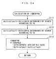
- FIG. 24 shows a process for calculating the first stage control target opening degree ICMDOFPRE.
- the above-mentioned map shown in FIG. 22 is searched according to the atmospheric pressure PA currently detected to thereby determine the map value DATHICOFPA, and the map value DATHICOFPA is set as a setting PA correction term dathicofpaxl.
- a step 112 the above-mentioned map shown in FIG. 23 is searched according to the intake air temperature TA currently detected to thereby determine the map value DATHICOFTA, and the map value DATHICOFTA is set as a setting TA correction term dathicoftax1.
- the first stage control target opening degree ICMDOFPRE is calculated using a basic value ICMDPREA, the target second stage control opening degree ATHICOFREFX, the initial value ATHICOFINI, a predetermined value KATH, and the setting PA correction term dathicofpax1 and setting TA correction term dathicoftax1 calculated as described above, by the following equation (13), followed by terminating the present process.
- ICMDOFPRE ICMDPREA - ATHICOFREFX - ATHICOFINI ⁇ KATH - dathicofpax ⁇ 1 - dathicoftax ⁇ 1
- the first stage control target opening degree ICMDOFPRE is set to a smaller value as the target second stage control opening degree ATHICOFREFX is larger.
- the fact that the target second stage control opening degree ATHICOFREFX is set to a large value by the learning of the target second stage control opening degree ATHICOFREFX described above represents a state where a time period required for the first stage control is liable to be long since the friction of the piston 3d is small to make the piston 3d difficult to be stopped. Therefore, the first stage control target opening degree ICMDOFPRE is set to a smaller value as the target second stage control opening degree ATHICOFREFX is larger (see FIG.
- the setting PA correction term dathicofpax1 is set to a larger value as the atmospheric pressure PA is lower, and the setting TA correction term dathicoftax1 is set to a larger value as the intake air temperature TA is higher.
- the first stage control target opening degree ICMDOFPRE is corrected such that it becomes smaller as the atmospheric pressure PA is lower and as the intake air temperature TA is higher. This makes it possible to set the first stage control target opening degree ICMDOFPRE in a more fine-grained manner according to the actual atmospheric pressure PA and intake air temperature TA, to more properly control the intake pressure PBA at the start of the second stage control, and therefore it is possible to further enhance the accuracy of the stop control of the piston 3d.
- FIGS. 25 and 26 show a process for setting the target opening degree ICMDTHIGOF of the throttle valve 13a.
- the present process first, in a step 121, it is determined whether or not the second stage control execution flag F_IGOFFTH2 is equal to 1. If the answer to this question is affirmative (YES), i.e. if the second stage control is being executed, the present process is immediately terminated.
- step 122 it is determined whether or not the fuel cut flag F_IGOFFFC is equal to 1. If the answer to this question is negative (NO), the first stage control execution flag F_IGOFFTH1 and the second stage control execution flag F_IGOFFTH2 are set to 0, respectively (steps 123 and 124), and the target opening degree ICMDTHIGOF is set to 0 (step 125), followed by terminating the present process.
- step 126 the above-mentioned map shown in FIG. 22 is searched according to the atmospheric pressure PA currently detected to determine the map value DATHICOFPA, whereby the map value DATHICOFPA is set as a setting PA correction term dathicofpax (step 126).
- a step 127 the above-mentioned map shown in FIG. 23 is searched according to the intake air temperature TA currently detected to thereby determine the map value DATHICOFTA, and the map value DATHICOFTA is set as a setting TA correction term dathicoftax.
- a corrected target second stage control opening degree ATHICOFREFN is calculated using the target second stage control opening degree ATHICOFREFX calculated in the step 101 in FIG. 20 , the calculated setting PA correction term dathicofpax and setting TA correction term dathicoftax, by the following equation (14):
- ATHICOFREFN ATHICOFREFX + dathicofpax + dathicoftax
- the density of intake air is lower and the resistance of intake air to the piston 3d is smaller, so that the rate of reduction of the engine speed NE becomes smaller.
- the control signal based on the target opening degree ICMDTHIGOF is delivered, there occurs a delay before the opening degree of the throttle valve 13a becomes commensurate with the control signal, and a further delay occurs before the intake air amount becomes large enough to be commensurate with the opening degree of the throttle valve 13a. Therefore, by correcting the corrected target second stage control opening degree ATHICOFREFN to a larger value as the atmospheric pressure PA is lower, to thereby increase the intake air amount, it is possible to properly avoid the adverse influence of the operation of the throttle valve 13a and the delay of intake air, described above.
- the corrected target second stage control opening degree ATHICOFREFN is corrected to a larger value as the intake air temperature TA is higher.
- the intake air temperature TA is higher, the sliding friction of the piston 3d is smaller, and the density of intake air is lower, which reduces the rate of reduction of the engine speed NE. Therefore, by correcting the corrected target second stage control opening degree ATHICOFREFN to a smaller value as the intake air temperature TA is lower to thereby reduce the intake air amount, it is possible to properly avoid the adverse influence of the operation of the throttle valve 13a and the delay of intake air.
- a step 129 it is determined whether or not the engine speed NE is smaller than a predetermined first stage control start rotational speed NEICOFPRE (e.g. 550 rpm). If the answer to this question is negative (NO), i.e. if NE ⁇ NEICOFPRE holds, the above-described steps 123 to 125 are executed, followed by terminating the present process.
- a predetermined first stage control start rotational speed NEICOFPRE e.g. 550 rpm.
- step 130 it is determined whether or not the first stage control execution flag F_IGOFFTH1 is equal to 1 (step 130). If the answer to this question is negative (NO), i.e. if the first stage control has not been executed yet, the target opening degree ICMDTHIGOF is set to the first stage control target opening degree ICMDOFPRE calculated in the step 113 in FIG. 24 (step 133), and the first stage control execution flag F_IGOFFTH1 is set to 1 (step 134), followed by terminating the present process.
- step 130 determines whether or not the stage number STG is 0 (step 131). If the answer to this question is negative (NO), the above-described steps 133 and 134 are executed, followed by terminating the present process.
- step 131 determines whether or not the engine speed NE is smaller than a predetermined stop control start rotational speed NEICOFREFN (e.g. 500 rpm) (step 132). If the answer to this question is negative (NO), i.e. if NEICOFREFN ⁇ NE ⁇ NEICOFPRE holds, the above-described steps 133 and 134 are executed to thereby continue the first stage control, followed by terminating the present process.
- a predetermined stop control start rotational speed NEICOFREFN e.g. 500 rpm
- step 132 determines whether the stage number STG is 0, and at the same time if the engine speed NE is lower than the stop control start rotational speed NEICOFREFN. If the answer to the question of the step 132 is affirmative (YES), i.e. if the stage number STG is 0, and at the same time if the engine speed NE is lower than the stop control start rotational speed NEICOFREFN, the process proceeds to a step 135, wherein the corrected target second stage control opening degree ATHICOFREFN calculated in the step 128 is stored as a second stage control opening degree ATHIGOFTH for the stop control, and the atmospheric pressure PA and the intake air temperature TA, which are currently detected, are stored as an atmospheric pressure PAO and an intake air temperature TA0 detected for the stop control (steps 136 and 137), respectively.
- the stored second stage control opening degree ATHIGOFTH is applied to the aforementioned equation (9), and the atmospheric pressure PA0 and the intake air temperature TA0 are used in the FIG. 20 steps 97 and 98, for calculating the learning PA correction term dathicofrpa and the learning TA correction term dathicofrta, respectively.
- the target opening degree ICMDTHIGOF is set to the corrected target second stage control opening degree ATHICOFREFN set in the step 128. Further, the second stage control execution flag F_IGOFFTH2 is set to 1 (step 139), followed by terminating the present process.
- the final compression stroke rotational speed NEPRSFTGT is calculated in the process shown in FIGS. 7 and 8 .
- the calculated final compression stroke rotational speed NEPRSFTGT is applied to the aforementioned equation (9), and is used for setting the target second stage control opening degree ATHICOFREFX.
- the first stage control target opening degree ICMDOFPRE is set to a smaller value as the target second stage control opening degree ATHICOFREFX is larger (see FIG. 28 ). Therefore, even when the target second stage control opening degree ATHICOFREFX is changed, the first stage control is executed by the intake air amount dependent on the change in the target second stage control opening degree ATHICOFREFX, whereby it is possible to stabilize the intake pressure PBA at the start of the second stage control, thereby making it possible to ensure the accuracy of the stop control of the piston 3d by the second stage control.
- the first stage control target opening degree ICMDOFPRE is corrected according to the actual atmospheric pressure PA and intake air temperature TA, it is possible to more properly set the first stage control target opening degree ICMDOFPRE, and therefore it is possible to further stabilize the intake pressure PBA at the start of the second stage control, thereby making it possible to further enhance the accuracy of the stop control of the piston 3d.
- the first stage control start rotational speed NEICOFPRE is a fixed value
- the first stage control start rotational speed NEICOFPRE may be corrected and set using the atmospheric pressure PA and the intake air temperature TA.
- a map shown in FIG. 10 is searched according to the atmospheric pressure PA to determine a map value DNEICOFPA, whereby the map value DNEICOFPA is set as the setting PA correction term dneicofpax
- a map shown in FIG. 11 is searched according to the intake air temperature TA to determine a map value DNEICOFTA, whereby the map value DNEICOFTA is set as the setting TA correction term dneicoftax.
- the second predetermined opening degree ICMDOF2 is calculated using a basic value NEICOFPREB of the first stage control start rotational speed and the setting PA correction term dneicofpax and the setting TA correction term dneicoftax, by the following equation (15):
- NEICOFPRE NEICOFPREB + dneicofpax + dneicoftax
- the map value DNEICOFPA is set to a larger value as the atmospheric pressure PA is higher, and in the map shown in FIG. 11 , the map value DNEICOFTA is set to a larger value as the intake air temperature TA is lower.
- the first stage control start rotational speed NEICOFPRE is corrected such that it becomes larger as the atmospheric pressure PA is higher and as the intake air temperature TA is lower. This makes it possible to set the first stage control start rotational speed NEICOFPRE in a more fine-grained manner according to the actual atmospheric pressure PA and intake air temperature TA, and therefore it is possible to further enhance the accuracy of the stop control of the piston 3d.
- the first stage control start rotational speed NEICOFPRE used in the step 129 in FIG. 25 is a fixed value.
- the first stage control start rotational speed NEICOFPRE is calculated according to the target second stage control opening degree ATHICOFREFX.
- a step 141 the above-mentioned map shown in FIG. 10 is searched according to the atmospheric pressure PA to thereby determine the map value DNEICOFPA, and the map value DNEICOFPA is set as a setting PA correction term dneicofpax1 for the first stage control start rotational speed.
- a step 142 the above-mentioned map shown in FIG. 11 is searched according to the intake air temperature TA to determine the map value DNEICOFTA, whereby the map value DNEICOFTA is set as a setting TA correction term dneicoftax1 for the first stage control start rotational speed.
- the first stage control start rotational speed NEICOFPRE is calculated using a predetermined basic value NEICPREB, the target second stage control opening degree ATHICOFREFX, the initial value ATHICOFINI, and a predetermined coefficient KATHNE, as well as the setting PA correction term dneicofpax1 and setting TA correction term dneicoftax1 calculated as described above, by the following equation (16):
- NEICOFPRE NEICPREB - ATHICOFREFX - ATHICOFINI ⁇ KATHNE + dneicofpax ⁇ 1 + dneicoftax ⁇ 1 followed by terminating the present process.
- the first stage control start rotational speed NEICOFPRE is set to a smaller value as the target second stage control opening degree ATHICOFREFX is larger.
- the fact that the target second stage control opening degree ATHICOFREFX is set to a large value by the learning of the target second stage control opening degree ATHICOFREFX described above represents a state where the time period required for the first stage control is liable to be long since the friction of the piston 3d is small to make the piston 3d difficult to be stopped. Therefore, the first stage control start rotational speed NEICOFPRE is set to a smaller value as the target second stage control opening degree ATHICOFREFX is larger (see FIG. 29 ), whereby the first stage control is started in later timing. As a consequence, it is possible to properly control the intake pressure PBA at the start of the second stage control irrespective of the target second stage control opening degree ATHICOFREFX.
- the setting PA correction term dneicofpax1 is set to a smaller value as the atmospheric pressure PA is lower and the setting TA correction term dneicoftax1 is set to a smaller value as the intake air temperature TA is higher.
- the first stage control start rotational speed NEICOFPRE is corrected such that it becomes smaller as the atmospheric pressure PA is lower and as the intake air temperature TA is higher. This makes it possible to set the first stage control start rotational speed NEICOFPRE in a more fine-grained manner according to the actual atmospheric pressure PA and intake air temperature TA, to thereby more properly control the intake pressure PBA at the start of the second stage control. Therefore, it is possible to further enhance the accuracy of the stop control of the piston 3d.
- the present invention is by no means limited to the embodiments described above, but can be practiced in various forms.
- the throttle valve 13a is used as the intake air amount-adjusting valve for adjusting the intake air amount during stoppage of the engine 3, in place of the throttle valve 13a, there may be used intake valves the lift of which can be changed by a variable intake lift mechanism.
- the correction of the target stop control start rotational speed NEICOFREFX or the first stage control target opening degree ICMDOFPRE is performed according to the atmospheric pressure PA and the intake air temperature TA
- the correction may be performed according to a parameter indicative of the temperature of the engine 3, such as the engine coolant temperature TW, in addition to or in place of the atmospheric pressure PA and the intake air temperature TA.
- the target stop control start rotational speed NEICOFREFX or the first stage control target opening degree ICMDOFPRE is corrected to a larger value.
- such correction may be carried out on the first stage control start rotational speed NEICOFPRE and/or the second predetermined opening degree ICMDOF2 for use in the second stage control.
- the stop control when the ignition switch 21 is turned off, judging that a command for stopping the engine 3 is issued, the stop control is executed, but in a case where an idle stop is executed in which the engine 3 is automatically stopped when predetermined stop conditions are satisfied, the stop control may be executed after satisfaction of the stop conditions.
- the present invention is applied to the gasoline engine installed on a vehicle, this is not limitative, but it can be applied to various engines other than the gasoline engine, e.g. a diesel engine, and further, it can be applied to engines other than the engines for a vehicle, e.g. engines for ship propulsion machines, such as an outboard motor having a vertically-disposed crankshaft. Further, it is possible to change details of the construction of the embodiment within the spirit and scope of the present invention.
- the stop control system according to the present invention is useful in accurately stopping the piston at a predetermined position while preventing occurrence of untoward noise and vibration during stoppage of the engine.
Applications Claiming Priority (2)
| Application Number | Priority Date | Filing Date | Title |
|---|---|---|---|
| JP2009177943 | 2009-07-30 | ||
| PCT/JP2010/062901 WO2011013800A1 (ja) | 2009-07-30 | 2010-07-30 | 内燃機関の停止制御装置および方法 |
Publications (3)
| Publication Number | Publication Date |
|---|---|
| EP2461008A1 true EP2461008A1 (de) | 2012-06-06 |
| EP2461008A4 EP2461008A4 (de) | 2013-03-06 |
| EP2461008B1 EP2461008B1 (de) | 2013-12-11 |
Family
ID=43529451
Family Applications (1)
| Application Number | Title | Priority Date | Filing Date |
|---|---|---|---|
| EP10804546.9A Not-in-force EP2461008B1 (de) | 2009-07-30 | 2010-07-30 | Stopp-steuervorrichtung und verfahren für verbrennungsmotor |
Country Status (5)
| Country | Link |
|---|---|
| US (1) | US8812221B2 (de) |
| EP (1) | EP2461008B1 (de) |
| JP (1) | JP5277316B2 (de) |
| CN (1) | CN102483003B (de) |
| WO (1) | WO2011013800A1 (de) |
Families Citing this family (12)
| Publication number | Priority date | Publication date | Assignee | Title |
|---|---|---|---|---|
| JP5601284B2 (ja) * | 2011-06-29 | 2014-10-08 | トヨタ自動車株式会社 | 内燃機関制御装置 |
| CN103889801A (zh) * | 2011-10-27 | 2014-06-25 | 丰田自动车株式会社 | 车辆控制装置 |
| DE102012203429A1 (de) * | 2012-03-05 | 2013-09-05 | Robert Bosch Gmbh | Verfahren und Vorrichtung zur Steuerung einer Brennkraftmaschine |
| US9322352B2 (en) * | 2012-05-14 | 2016-04-26 | GM Global Technology Operations LLC | System and method for preventing misfire during engine startup |
| US9249750B2 (en) | 2012-11-08 | 2016-02-02 | GM Global Technology Operations LLC | System and method for controlling fuel injection when an engine is automatically started to decrease an engine startup period |
| DE102014207583A1 (de) * | 2014-04-22 | 2015-10-22 | Robert Bosch Gmbh | Verfahren zum Stoppen einer Brennkraftmaschine |
| US10099675B2 (en) | 2014-10-27 | 2018-10-16 | GM Global Technology Operations LLC | System and method for improving fuel economy and reducing emissions when a vehicle is decelerating |
| JP6287889B2 (ja) * | 2015-02-19 | 2018-03-07 | トヨタ自動車株式会社 | 多気筒内燃機関の制御装置 |
| DE102017221320A1 (de) * | 2017-11-28 | 2019-05-29 | Bayerische Motoren Werke Aktiengesellschaft | Verfahren und Steuereinheit zur Durchführung eines Motorstopps eines Verbrennungsmotors |
| KR102575142B1 (ko) * | 2018-03-07 | 2023-09-06 | 현대자동차주식회사 | 엔진의 시동 오프시 진동 저감 장치 및 그 방법 |
| WO2020022062A1 (ja) * | 2018-07-27 | 2020-01-30 | アイシン精機株式会社 | 内燃機関 |
| JP2022149282A (ja) * | 2021-03-25 | 2022-10-06 | マツダ株式会社 | エンジンの始動制御装置 |
Citations (4)
| Publication number | Priority date | Publication date | Assignee | Title |
|---|---|---|---|---|
| EP1367246A1 (de) * | 2002-05-14 | 2003-12-03 | Ford Global Technologies, LLC, A subsidary of Ford Motor Company | Verfahren zur Abstellung einer Brennkraftmaschine und Vorbereitung ihres Anlassens |
| EP1582738A2 (de) * | 2004-03-29 | 2005-10-05 | Mazda Motor Corporation | Vorrichtung zum Anlassen einer Brennkraftmaschine |
| WO2006134470A1 (en) * | 2005-06-16 | 2006-12-21 | Toyota Jidosha Kabushiki Kaisha | Starting system and method of internal combustion engine |
| WO2008072063A2 (en) * | 2006-12-11 | 2008-06-19 | Toyota Jidosha Kabushiki Kaisha | Control apparatus and method for internal combustion engine |
Family Cites Families (10)
| Publication number | Priority date | Publication date | Assignee | Title |
|---|---|---|---|---|
| JPH01203626A (ja) * | 1988-02-07 | 1989-08-16 | Honda Motor Co Ltd | 内燃エンジンの始動制御装置並びに吸入空気量制御装置 |
| JPH0599016A (ja) * | 1991-10-09 | 1993-04-20 | Toyota Motor Corp | 最高速制御装置 |
| JP3356033B2 (ja) | 1997-11-28 | 2002-12-09 | 三菱自動車工業株式会社 | 内燃機関のスロットルバルブ装置 |
| JP2002161758A (ja) * | 2000-11-27 | 2002-06-07 | Denso Corp | 内燃機関のスロットル制御装置 |
| DE60236394D1 (de) * | 2001-09-20 | 2010-07-01 | Honda Motor Co Ltd | Regelungseinrichtung für Mehrzweckmotor |
| JP4412025B2 (ja) * | 2004-03-29 | 2010-02-10 | マツダ株式会社 | エンジンの始動装置 |
| JP2006118477A (ja) * | 2004-10-25 | 2006-05-11 | Kokusan Denki Co Ltd | 発電機を搭載したエンジン駆動車両の制御装置 |
| JP4550627B2 (ja) | 2005-03-02 | 2010-09-22 | 日立オートモティブシステムズ株式会社 | 内燃機関の停止制御方法および停止制御装置 |
| JP2008180096A (ja) * | 2007-01-23 | 2008-08-07 | Nissan Motor Co Ltd | エンジンの始動装置 |
| EP2461007B1 (de) * | 2009-07-30 | 2015-02-25 | Honda Motor Co., Ltd. | Stoppsteuervorrichtung und -verfahren für einen verbrennungsmotor |
-
2010
- 2010-07-30 JP JP2011524854A patent/JP5277316B2/ja not_active Expired - Fee Related
- 2010-07-30 EP EP10804546.9A patent/EP2461008B1/de not_active Not-in-force
- 2010-07-30 CN CN201080027964.5A patent/CN102483003B/zh active Active
- 2010-07-30 US US13/384,744 patent/US8812221B2/en active Active
- 2010-07-30 WO PCT/JP2010/062901 patent/WO2011013800A1/ja active Application Filing
Patent Citations (4)
| Publication number | Priority date | Publication date | Assignee | Title |
|---|---|---|---|---|
| EP1367246A1 (de) * | 2002-05-14 | 2003-12-03 | Ford Global Technologies, LLC, A subsidary of Ford Motor Company | Verfahren zur Abstellung einer Brennkraftmaschine und Vorbereitung ihres Anlassens |
| EP1582738A2 (de) * | 2004-03-29 | 2005-10-05 | Mazda Motor Corporation | Vorrichtung zum Anlassen einer Brennkraftmaschine |
| WO2006134470A1 (en) * | 2005-06-16 | 2006-12-21 | Toyota Jidosha Kabushiki Kaisha | Starting system and method of internal combustion engine |
| WO2008072063A2 (en) * | 2006-12-11 | 2008-06-19 | Toyota Jidosha Kabushiki Kaisha | Control apparatus and method for internal combustion engine |
Non-Patent Citations (1)
| Title |
|---|
| See also references of WO2011013800A1 * |
Also Published As
| Publication number | Publication date |
|---|---|
| JPWO2011013800A1 (ja) | 2013-01-10 |
| US8812221B2 (en) | 2014-08-19 |
| JP5277316B2 (ja) | 2013-08-28 |
| WO2011013800A1 (ja) | 2011-02-03 |
| CN102483003A (zh) | 2012-05-30 |
| EP2461008A4 (de) | 2013-03-06 |
| CN102483003B (zh) | 2015-11-25 |
| US20120130619A1 (en) | 2012-05-24 |
| EP2461008B1 (de) | 2013-12-11 |
Similar Documents
| Publication | Publication Date | Title |
|---|---|---|
| EP2461008B1 (de) | Stopp-steuervorrichtung und verfahren für verbrennungsmotor | |
| EP2461007B1 (de) | Stoppsteuervorrichtung und -verfahren für einen verbrennungsmotor | |
| US8141533B2 (en) | Control apparatus and method for internal combustion engine | |
| KR100980886B1 (ko) | 키 오프시 진동 저감 시스템 및 그 방법 | |
| US8554451B2 (en) | Stop control system for internal combustion engine | |
| EP2357340B1 (de) | Vorrichtung und verfahren zur steuerung des zeitpunkts eines zündungsstopps beim stopp eines verbrennungsmotors | |
| US7520255B2 (en) | Control for an engine having a variable valve-driving unit | |
| US7831377B2 (en) | Ignition timing control system and method for internal combustion engine and engine control unit | |
| EP2251538B1 (de) | Ansaugsteuerungssystem und Verfahren für einen Verbrennungsmotor | |
| US8428854B2 (en) | Internal EGR control system for internal combustion engine | |
| EP2466099B1 (de) | Stopp-Steuervorrichtung für Verbrennungsmotor | |
| EP1215386B1 (de) | Vorrichtung und Verfahren zur Diagnose eines Kraftstoffversorgungssystems | |
| JP2007056783A (ja) | ディーゼル内燃機関の制御装置 | |
| US10113490B2 (en) | Control apparatus for internal combustion engine | |
| US20120323467A1 (en) | Fuel injection amount calculation method and fuel injection controlling apparatus | |
| JP4168739B2 (ja) | 内燃機関の気筒間ばらつき検出装置 | |
| JP2010174676A (ja) | 内燃機関の停止制御装置 | |
| US8275539B2 (en) | Control system and method for internal combustion engine | |
| JP5023126B2 (ja) | 内燃機関の停止制御装置 | |
| JP5439228B2 (ja) | 内燃機関の制御装置 | |
| JP2011012616A (ja) | 内燃機関の制御装置 |
Legal Events
| Date | Code | Title | Description |
|---|---|---|---|
| PUAI | Public reference made under article 153(3) epc to a published international application that has entered the european phase |
Free format text: ORIGINAL CODE: 0009012 |
|
| 17P | Request for examination filed |
Effective date: 20120116 |
|
| AK | Designated contracting states |
Kind code of ref document: A1 Designated state(s): AL AT BE BG CH CY CZ DE DK EE ES FI FR GB GR HR HU IE IS IT LI LT LU LV MC MK MT NL NO PL PT RO SE SI SK SM TR |
|
| DAX | Request for extension of the european patent (deleted) | ||
| A4 | Supplementary search report drawn up and despatched |
Effective date: 20130131 |
|
| RIC1 | Information provided on ipc code assigned before grant |
Ipc: F02D 45/00 20060101ALI20130125BHEP Ipc: F02D 9/02 20060101ALI20130125BHEP Ipc: F02D 41/04 20060101ALI20130125BHEP Ipc: F02D 29/02 20060101AFI20130125BHEP Ipc: F02D 11/10 20060101ALI20130125BHEP Ipc: F02D 17/00 20060101ALI20130125BHEP |
|
| GRAP | Despatch of communication of intention to grant a patent |
Free format text: ORIGINAL CODE: EPIDOSNIGR1 |
|
| INTG | Intention to grant announced |
Effective date: 20130722 |
|
| GRAS | Grant fee paid |
Free format text: ORIGINAL CODE: EPIDOSNIGR3 |
|
| GRAA | (expected) grant |
Free format text: ORIGINAL CODE: 0009210 |
|
| AK | Designated contracting states |
Kind code of ref document: B1 Designated state(s): AL AT BE BG CH CY CZ DE DK EE ES FI FR GB GR HR HU IE IS IT LI LT LU LV MC MK MT NL NO PL PT RO SE SI SK SM TR |
|
| REG | Reference to a national code |
Ref country code: GB Ref legal event code: FG4D |
|
| REG | Reference to a national code |
Ref country code: CH Ref legal event code: EP |
|
| REG | Reference to a national code |
Ref country code: AT Ref legal event code: REF Ref document number: 644744 Country of ref document: AT Kind code of ref document: T Effective date: 20140115 |
|
| REG | Reference to a national code |
Ref country code: IE Ref legal event code: FG4D |
|
| REG | Reference to a national code |
Ref country code: DE Ref legal event code: R096 Ref document number: 602010012450 Country of ref document: DE Effective date: 20140206 |
|
| REG | Reference to a national code |
Ref country code: NL Ref legal event code: VDEP Effective date: 20131211 |
|
| REG | Reference to a national code |
Ref country code: AT Ref legal event code: MK05 Ref document number: 644744 Country of ref document: AT Kind code of ref document: T Effective date: 20131211 |
|
| PG25 | Lapsed in a contracting state [announced via postgrant information from national office to epo] |
Ref country code: NO Free format text: LAPSE BECAUSE OF FAILURE TO SUBMIT A TRANSLATION OF THE DESCRIPTION OR TO PAY THE FEE WITHIN THE PRESCRIBED TIME-LIMIT Effective date: 20140311 Ref country code: LT Free format text: LAPSE BECAUSE OF FAILURE TO SUBMIT A TRANSLATION OF THE DESCRIPTION OR TO PAY THE FEE WITHIN THE PRESCRIBED TIME-LIMIT Effective date: 20131211 Ref country code: FI Free format text: LAPSE BECAUSE OF FAILURE TO SUBMIT A TRANSLATION OF THE DESCRIPTION OR TO PAY THE FEE WITHIN THE PRESCRIBED TIME-LIMIT Effective date: 20131211 Ref country code: HR Free format text: LAPSE BECAUSE OF FAILURE TO SUBMIT A TRANSLATION OF THE DESCRIPTION OR TO PAY THE FEE WITHIN THE PRESCRIBED TIME-LIMIT Effective date: 20131211 Ref country code: NL Free format text: LAPSE BECAUSE OF FAILURE TO SUBMIT A TRANSLATION OF THE DESCRIPTION OR TO PAY THE FEE WITHIN THE PRESCRIBED TIME-LIMIT Effective date: 20131211 Ref country code: SE Free format text: LAPSE BECAUSE OF FAILURE TO SUBMIT A TRANSLATION OF THE DESCRIPTION OR TO PAY THE FEE WITHIN THE PRESCRIBED TIME-LIMIT Effective date: 20131211 |
|
| REG | Reference to a national code |
Ref country code: LT Ref legal event code: MG4D |
|
| PG25 | Lapsed in a contracting state [announced via postgrant information from national office to epo] |
Ref country code: CY Free format text: LAPSE BECAUSE OF FAILURE TO SUBMIT A TRANSLATION OF THE DESCRIPTION OR TO PAY THE FEE WITHIN THE PRESCRIBED TIME-LIMIT Effective date: 20131211 Ref country code: AT Free format text: LAPSE BECAUSE OF FAILURE TO SUBMIT A TRANSLATION OF THE DESCRIPTION OR TO PAY THE FEE WITHIN THE PRESCRIBED TIME-LIMIT Effective date: 20131211 Ref country code: LV Free format text: LAPSE BECAUSE OF FAILURE TO SUBMIT A TRANSLATION OF THE DESCRIPTION OR TO PAY THE FEE WITHIN THE PRESCRIBED TIME-LIMIT Effective date: 20131211 |
|
| PG25 | Lapsed in a contracting state [announced via postgrant information from national office to epo] |
Ref country code: IS Free format text: LAPSE BECAUSE OF FAILURE TO SUBMIT A TRANSLATION OF THE DESCRIPTION OR TO PAY THE FEE WITHIN THE PRESCRIBED TIME-LIMIT Effective date: 20140411 Ref country code: BE Free format text: LAPSE BECAUSE OF FAILURE TO SUBMIT A TRANSLATION OF THE DESCRIPTION OR TO PAY THE FEE WITHIN THE PRESCRIBED TIME-LIMIT Effective date: 20131211 Ref country code: EE Free format text: LAPSE BECAUSE OF FAILURE TO SUBMIT A TRANSLATION OF THE DESCRIPTION OR TO PAY THE FEE WITHIN THE PRESCRIBED TIME-LIMIT Effective date: 20131211 |
|
| PG25 | Lapsed in a contracting state [announced via postgrant information from national office to epo] |
Ref country code: SK Free format text: LAPSE BECAUSE OF FAILURE TO SUBMIT A TRANSLATION OF THE DESCRIPTION OR TO PAY THE FEE WITHIN THE PRESCRIBED TIME-LIMIT Effective date: 20131211 Ref country code: PL Free format text: LAPSE BECAUSE OF FAILURE TO SUBMIT A TRANSLATION OF THE DESCRIPTION OR TO PAY THE FEE WITHIN THE PRESCRIBED TIME-LIMIT Effective date: 20131211 Ref country code: ES Free format text: LAPSE BECAUSE OF FAILURE TO SUBMIT A TRANSLATION OF THE DESCRIPTION OR TO PAY THE FEE WITHIN THE PRESCRIBED TIME-LIMIT Effective date: 20131211 Ref country code: RO Free format text: LAPSE BECAUSE OF FAILURE TO SUBMIT A TRANSLATION OF THE DESCRIPTION OR TO PAY THE FEE WITHIN THE PRESCRIBED TIME-LIMIT Effective date: 20131211 Ref country code: PT Free format text: LAPSE BECAUSE OF FAILURE TO SUBMIT A TRANSLATION OF THE DESCRIPTION OR TO PAY THE FEE WITHIN THE PRESCRIBED TIME-LIMIT Effective date: 20140411 Ref country code: CZ Free format text: LAPSE BECAUSE OF FAILURE TO SUBMIT A TRANSLATION OF THE DESCRIPTION OR TO PAY THE FEE WITHIN THE PRESCRIBED TIME-LIMIT Effective date: 20131211 |
|
| REG | Reference to a national code |
Ref country code: DE Ref legal event code: R097 Ref document number: 602010012450 Country of ref document: DE |
|
| PLBE | No opposition filed within time limit |
Free format text: ORIGINAL CODE: 0009261 |
|
| STAA | Information on the status of an ep patent application or granted ep patent |
Free format text: STATUS: NO OPPOSITION FILED WITHIN TIME LIMIT |
|
| PG25 | Lapsed in a contracting state [announced via postgrant information from national office to epo] |
Ref country code: DK Free format text: LAPSE BECAUSE OF FAILURE TO SUBMIT A TRANSLATION OF THE DESCRIPTION OR TO PAY THE FEE WITHIN THE PRESCRIBED TIME-LIMIT Effective date: 20131211 |
|
| 26N | No opposition filed |
Effective date: 20140912 |
|
| REG | Reference to a national code |
Ref country code: DE Ref legal event code: R097 Ref document number: 602010012450 Country of ref document: DE Effective date: 20140912 |
|
| PG25 | Lapsed in a contracting state [announced via postgrant information from national office to epo] |
Ref country code: SI Free format text: LAPSE BECAUSE OF FAILURE TO SUBMIT A TRANSLATION OF THE DESCRIPTION OR TO PAY THE FEE WITHIN THE PRESCRIBED TIME-LIMIT Effective date: 20131211 Ref country code: LU Free format text: LAPSE BECAUSE OF FAILURE TO SUBMIT A TRANSLATION OF THE DESCRIPTION OR TO PAY THE FEE WITHIN THE PRESCRIBED TIME-LIMIT Effective date: 20140730 |
|
| REG | Reference to a national code |
Ref country code: CH Ref legal event code: PL |
|
| REG | Reference to a national code |
Ref country code: IE Ref legal event code: MM4A |
|
| REG | Reference to a national code |
Ref country code: FR Ref legal event code: ST Effective date: 20150331 |
|
| PG25 | Lapsed in a contracting state [announced via postgrant information from national office to epo] |
Ref country code: CH Free format text: LAPSE BECAUSE OF NON-PAYMENT OF DUE FEES Effective date: 20140731 Ref country code: LI Free format text: LAPSE BECAUSE OF NON-PAYMENT OF DUE FEES Effective date: 20140731 |
|
| PG25 | Lapsed in a contracting state [announced via postgrant information from national office to epo] |
Ref country code: FR Free format text: LAPSE BECAUSE OF NON-PAYMENT OF DUE FEES Effective date: 20140731 |
|
| PG25 | Lapsed in a contracting state [announced via postgrant information from national office to epo] |
Ref country code: IE Free format text: LAPSE BECAUSE OF NON-PAYMENT OF DUE FEES Effective date: 20140730 |
|
| PG25 | Lapsed in a contracting state [announced via postgrant information from national office to epo] |
Ref country code: MC Free format text: LAPSE BECAUSE OF FAILURE TO SUBMIT A TRANSLATION OF THE DESCRIPTION OR TO PAY THE FEE WITHIN THE PRESCRIBED TIME-LIMIT Effective date: 20131211 Ref country code: SM Free format text: LAPSE BECAUSE OF FAILURE TO SUBMIT A TRANSLATION OF THE DESCRIPTION OR TO PAY THE FEE WITHIN THE PRESCRIBED TIME-LIMIT Effective date: 20131211 |
|
| PG25 | Lapsed in a contracting state [announced via postgrant information from national office to epo] |
Ref country code: GR Free format text: LAPSE BECAUSE OF FAILURE TO SUBMIT A TRANSLATION OF THE DESCRIPTION OR TO PAY THE FEE WITHIN THE PRESCRIBED TIME-LIMIT Effective date: 20140312 Ref country code: IT Free format text: LAPSE BECAUSE OF FAILURE TO SUBMIT A TRANSLATION OF THE DESCRIPTION OR TO PAY THE FEE WITHIN THE PRESCRIBED TIME-LIMIT Effective date: 20131211 Ref country code: MT Free format text: LAPSE BECAUSE OF FAILURE TO SUBMIT A TRANSLATION OF THE DESCRIPTION OR TO PAY THE FEE WITHIN THE PRESCRIBED TIME-LIMIT Effective date: 20131211 Ref country code: BG Free format text: LAPSE BECAUSE OF FAILURE TO SUBMIT A TRANSLATION OF THE DESCRIPTION OR TO PAY THE FEE WITHIN THE PRESCRIBED TIME-LIMIT Effective date: 20131211 |
|
| PG25 | Lapsed in a contracting state [announced via postgrant information from national office to epo] |
Ref country code: TR Free format text: LAPSE BECAUSE OF FAILURE TO SUBMIT A TRANSLATION OF THE DESCRIPTION OR TO PAY THE FEE WITHIN THE PRESCRIBED TIME-LIMIT Effective date: 20131211 Ref country code: HU Free format text: LAPSE BECAUSE OF FAILURE TO SUBMIT A TRANSLATION OF THE DESCRIPTION OR TO PAY THE FEE WITHIN THE PRESCRIBED TIME-LIMIT; INVALID AB INITIO Effective date: 20100730 |
|
| REG | Reference to a national code |
Ref country code: DE Ref legal event code: R084 Ref document number: 602010012450 Country of ref document: DE |
|
| REG | Reference to a national code |
Ref country code: GB Ref legal event code: 746 Effective date: 20170815 |
|
| PG25 | Lapsed in a contracting state [announced via postgrant information from national office to epo] |
Ref country code: MK Free format text: LAPSE BECAUSE OF FAILURE TO SUBMIT A TRANSLATION OF THE DESCRIPTION OR TO PAY THE FEE WITHIN THE PRESCRIBED TIME-LIMIT Effective date: 20131211 |
|
| PG25 | Lapsed in a contracting state [announced via postgrant information from national office to epo] |
Ref country code: AL Free format text: LAPSE BECAUSE OF FAILURE TO SUBMIT A TRANSLATION OF THE DESCRIPTION OR TO PAY THE FEE WITHIN THE PRESCRIBED TIME-LIMIT Effective date: 20131211 |
|
| PGFP | Annual fee paid to national office [announced via postgrant information from national office to epo] |
Ref country code: GB Payment date: 20210701 Year of fee payment: 12 Ref country code: DE Payment date: 20210630 Year of fee payment: 12 |
|
| REG | Reference to a national code |
Ref country code: DE Ref legal event code: R119 Ref document number: 602010012450 Country of ref document: DE |
|
| GBPC | Gb: european patent ceased through non-payment of renewal fee |
Effective date: 20220730 |
|
| PG25 | Lapsed in a contracting state [announced via postgrant information from national office to epo] |
Ref country code: GB Free format text: LAPSE BECAUSE OF NON-PAYMENT OF DUE FEES Effective date: 20220730 Ref country code: DE Free format text: LAPSE BECAUSE OF NON-PAYMENT OF DUE FEES Effective date: 20230201 |