EP2460694A1 - Operation system for vehicle - Google Patents
Operation system for vehicle Download PDFInfo
- Publication number
- EP2460694A1 EP2460694A1 EP10804260A EP10804260A EP2460694A1 EP 2460694 A1 EP2460694 A1 EP 2460694A1 EP 10804260 A EP10804260 A EP 10804260A EP 10804260 A EP10804260 A EP 10804260A EP 2460694 A1 EP2460694 A1 EP 2460694A1
- Authority
- EP
- European Patent Office
- Prior art keywords
- displayed
- icon
- display
- screen
- selection screen
- Prior art date
- Legal status (The legal status is an assumption and is not a legal conclusion. Google has not performed a legal analysis and makes no representation as to the accuracy of the status listed.)
- Ceased
Links
Images






Classifications
-
- G—PHYSICS
- G06—COMPUTING OR CALCULATING; COUNTING
- G06F—ELECTRIC DIGITAL DATA PROCESSING
- G06F3/00—Input arrangements for transferring data to be processed into a form capable of being handled by the computer; Output arrangements for transferring data from processing unit to output unit, e.g. interface arrangements
- G06F3/01—Input arrangements or combined input and output arrangements for interaction between user and computer
- G06F3/048—Interaction techniques based on graphical user interfaces [GUI]
- G06F3/0487—Interaction techniques based on graphical user interfaces [GUI] using specific features provided by the input device, e.g. functions controlled by the rotation of a mouse with dual sensing arrangements, or of the nature of the input device, e.g. tap gestures based on pressure sensed by a digitiser
- G06F3/0488—Interaction techniques based on graphical user interfaces [GUI] using specific features provided by the input device, e.g. functions controlled by the rotation of a mouse with dual sensing arrangements, or of the nature of the input device, e.g. tap gestures based on pressure sensed by a digitiser using a touch-screen or digitiser, e.g. input of commands through traced gestures
- G06F3/04886—Interaction techniques based on graphical user interfaces [GUI] using specific features provided by the input device, e.g. functions controlled by the rotation of a mouse with dual sensing arrangements, or of the nature of the input device, e.g. tap gestures based on pressure sensed by a digitiser using a touch-screen or digitiser, e.g. input of commands through traced gestures by partitioning the display area of the touch-screen or the surface of the digitising tablet into independently controllable areas, e.g. virtual keyboards or menus
-
- B—PERFORMING OPERATIONS; TRANSPORTING
- B60—VEHICLES IN GENERAL
- B60K—ARRANGEMENT OR MOUNTING OF PROPULSION UNITS OR OF TRANSMISSIONS IN VEHICLES; ARRANGEMENT OR MOUNTING OF PLURAL DIVERSE PRIME-MOVERS IN VEHICLES; AUXILIARY DRIVES FOR VEHICLES; INSTRUMENTATION OR DASHBOARDS FOR VEHICLES; ARRANGEMENTS IN CONNECTION WITH COOLING, AIR INTAKE, GAS EXHAUST OR FUEL SUPPLY OF PROPULSION UNITS IN VEHICLES
- B60K35/00—Instruments specially adapted for vehicles; Arrangement of instruments in or on vehicles
- B60K35/10—Input arrangements, i.e. from user to vehicle, associated with vehicle functions or specially adapted therefor
-
- B—PERFORMING OPERATIONS; TRANSPORTING
- B60—VEHICLES IN GENERAL
- B60K—ARRANGEMENT OR MOUNTING OF PROPULSION UNITS OR OF TRANSMISSIONS IN VEHICLES; ARRANGEMENT OR MOUNTING OF PLURAL DIVERSE PRIME-MOVERS IN VEHICLES; AUXILIARY DRIVES FOR VEHICLES; INSTRUMENTATION OR DASHBOARDS FOR VEHICLES; ARRANGEMENTS IN CONNECTION WITH COOLING, AIR INTAKE, GAS EXHAUST OR FUEL SUPPLY OF PROPULSION UNITS IN VEHICLES
- B60K35/00—Instruments specially adapted for vehicles; Arrangement of instruments in or on vehicles
- B60K35/20—Output arrangements, i.e. from vehicle to user, associated with vehicle functions or specially adapted therefor
-
- B—PERFORMING OPERATIONS; TRANSPORTING
- B60—VEHICLES IN GENERAL
- B60K—ARRANGEMENT OR MOUNTING OF PROPULSION UNITS OR OF TRANSMISSIONS IN VEHICLES; ARRANGEMENT OR MOUNTING OF PLURAL DIVERSE PRIME-MOVERS IN VEHICLES; AUXILIARY DRIVES FOR VEHICLES; INSTRUMENTATION OR DASHBOARDS FOR VEHICLES; ARRANGEMENTS IN CONNECTION WITH COOLING, AIR INTAKE, GAS EXHAUST OR FUEL SUPPLY OF PROPULSION UNITS IN VEHICLES
- B60K35/00—Instruments specially adapted for vehicles; Arrangement of instruments in or on vehicles
- B60K35/20—Output arrangements, i.e. from vehicle to user, associated with vehicle functions or specially adapted therefor
- B60K35/21—Output arrangements, i.e. from vehicle to user, associated with vehicle functions or specially adapted therefor using visual output, e.g. blinking lights or matrix displays
- B60K35/22—Display screens
-
- B—PERFORMING OPERATIONS; TRANSPORTING
- B60—VEHICLES IN GENERAL
- B60K—ARRANGEMENT OR MOUNTING OF PROPULSION UNITS OR OF TRANSMISSIONS IN VEHICLES; ARRANGEMENT OR MOUNTING OF PLURAL DIVERSE PRIME-MOVERS IN VEHICLES; AUXILIARY DRIVES FOR VEHICLES; INSTRUMENTATION OR DASHBOARDS FOR VEHICLES; ARRANGEMENTS IN CONNECTION WITH COOLING, AIR INTAKE, GAS EXHAUST OR FUEL SUPPLY OF PROPULSION UNITS IN VEHICLES
- B60K35/00—Instruments specially adapted for vehicles; Arrangement of instruments in or on vehicles
- B60K35/80—Arrangements for controlling instruments
- B60K35/81—Arrangements for controlling instruments for controlling displays
-
- B—PERFORMING OPERATIONS; TRANSPORTING
- B60—VEHICLES IN GENERAL
- B60K—ARRANGEMENT OR MOUNTING OF PROPULSION UNITS OR OF TRANSMISSIONS IN VEHICLES; ARRANGEMENT OR MOUNTING OF PLURAL DIVERSE PRIME-MOVERS IN VEHICLES; AUXILIARY DRIVES FOR VEHICLES; INSTRUMENTATION OR DASHBOARDS FOR VEHICLES; ARRANGEMENTS IN CONNECTION WITH COOLING, AIR INTAKE, GAS EXHAUST OR FUEL SUPPLY OF PROPULSION UNITS IN VEHICLES
- B60K2360/00—Indexing scheme associated with groups B60K35/00 or B60K37/00 relating to details of instruments or dashboards
- B60K2360/11—Instrument graphical user interfaces or menu aspects
-
- B—PERFORMING OPERATIONS; TRANSPORTING
- B60—VEHICLES IN GENERAL
- B60K—ARRANGEMENT OR MOUNTING OF PROPULSION UNITS OR OF TRANSMISSIONS IN VEHICLES; ARRANGEMENT OR MOUNTING OF PLURAL DIVERSE PRIME-MOVERS IN VEHICLES; AUXILIARY DRIVES FOR VEHICLES; INSTRUMENTATION OR DASHBOARDS FOR VEHICLES; ARRANGEMENTS IN CONNECTION WITH COOLING, AIR INTAKE, GAS EXHAUST OR FUEL SUPPLY OF PROPULSION UNITS IN VEHICLES
- B60K2360/00—Indexing scheme associated with groups B60K35/00 or B60K37/00 relating to details of instruments or dashboards
- B60K2360/122—Instrument input devices with reconfigurable control functions, e.g. reconfigurable menus
-
- B—PERFORMING OPERATIONS; TRANSPORTING
- B60—VEHICLES IN GENERAL
- B60K—ARRANGEMENT OR MOUNTING OF PROPULSION UNITS OR OF TRANSMISSIONS IN VEHICLES; ARRANGEMENT OR MOUNTING OF PLURAL DIVERSE PRIME-MOVERS IN VEHICLES; AUXILIARY DRIVES FOR VEHICLES; INSTRUMENTATION OR DASHBOARDS FOR VEHICLES; ARRANGEMENTS IN CONNECTION WITH COOLING, AIR INTAKE, GAS EXHAUST OR FUEL SUPPLY OF PROPULSION UNITS IN VEHICLES
- B60K2360/00—Indexing scheme associated with groups B60K35/00 or B60K37/00 relating to details of instruments or dashboards
- B60K2360/141—Activation of instrument input devices by approaching fingers or pens
-
- B—PERFORMING OPERATIONS; TRANSPORTING
- B60—VEHICLES IN GENERAL
- B60K—ARRANGEMENT OR MOUNTING OF PROPULSION UNITS OR OF TRANSMISSIONS IN VEHICLES; ARRANGEMENT OR MOUNTING OF PLURAL DIVERSE PRIME-MOVERS IN VEHICLES; AUXILIARY DRIVES FOR VEHICLES; INSTRUMENTATION OR DASHBOARDS FOR VEHICLES; ARRANGEMENTS IN CONNECTION WITH COOLING, AIR INTAKE, GAS EXHAUST OR FUEL SUPPLY OF PROPULSION UNITS IN VEHICLES
- B60K2360/00—Indexing scheme associated with groups B60K35/00 or B60K37/00 relating to details of instruments or dashboards
- B60K2360/143—Touch sensitive instrument input devices
- B60K2360/1438—Touch screens
- B60K2360/1442—Emulation of input devices
-
- B—PERFORMING OPERATIONS; TRANSPORTING
- B60—VEHICLES IN GENERAL
- B60K—ARRANGEMENT OR MOUNTING OF PROPULSION UNITS OR OF TRANSMISSIONS IN VEHICLES; ARRANGEMENT OR MOUNTING OF PLURAL DIVERSE PRIME-MOVERS IN VEHICLES; AUXILIARY DRIVES FOR VEHICLES; INSTRUMENTATION OR DASHBOARDS FOR VEHICLES; ARRANGEMENTS IN CONNECTION WITH COOLING, AIR INTAKE, GAS EXHAUST OR FUEL SUPPLY OF PROPULSION UNITS IN VEHICLES
- B60K2360/00—Indexing scheme associated with groups B60K35/00 or B60K37/00 relating to details of instruments or dashboards
- B60K2360/151—Instrument output devices for configurable output
- B60K2360/1515—Reconfigurable dials
-
- B—PERFORMING OPERATIONS; TRANSPORTING
- B60—VEHICLES IN GENERAL
- B60K—ARRANGEMENT OR MOUNTING OF PROPULSION UNITS OR OF TRANSMISSIONS IN VEHICLES; ARRANGEMENT OR MOUNTING OF PLURAL DIVERSE PRIME-MOVERS IN VEHICLES; AUXILIARY DRIVES FOR VEHICLES; INSTRUMENTATION OR DASHBOARDS FOR VEHICLES; ARRANGEMENTS IN CONNECTION WITH COOLING, AIR INTAKE, GAS EXHAUST OR FUEL SUPPLY OF PROPULSION UNITS IN VEHICLES
- B60K35/00—Instruments specially adapted for vehicles; Arrangement of instruments in or on vehicles
- B60K35/60—Instruments characterised by their location or relative disposition in or on vehicles
-
- B—PERFORMING OPERATIONS; TRANSPORTING
- B60—VEHICLES IN GENERAL
- B60K—ARRANGEMENT OR MOUNTING OF PROPULSION UNITS OR OF TRANSMISSIONS IN VEHICLES; ARRANGEMENT OR MOUNTING OF PLURAL DIVERSE PRIME-MOVERS IN VEHICLES; AUXILIARY DRIVES FOR VEHICLES; INSTRUMENTATION OR DASHBOARDS FOR VEHICLES; ARRANGEMENTS IN CONNECTION WITH COOLING, AIR INTAKE, GAS EXHAUST OR FUEL SUPPLY OF PROPULSION UNITS IN VEHICLES
- B60K37/00—Dashboards
Definitions
- the present invention relates to an operation system for a vehicle.
- Priority is claimed on Japanese Patent Application No. 2009-179289, filed July 31, 2009 , the content of which is incorporated herein by reference.
- An operation system for a vehicle which operates in-vehicle devices, has been known hitherto.
- system changeover switches are always displayed on a main monitor which is a touch panel. Accordingly, it is possible to operate in-vehicle devices, which correspond to the system changeover switches, anytime.
- the invention has been made in consideration of the above-mentioned circumstances, and an object of the invention is to provide an operation system for a vehicle that is capable of reducing the burden on a user by preventing the deterioration of operability caused by operating layers.
- the invention employs the following tool in order to achieve the object by solving the above-mentioned problem.
- all icons formed of characters or figures, which represent the current set value or the current operation mode of the operation items of the in-vehicle devices, are displayed on one screen of the display unit as the icon display screen, and a user selects the icon displayed on the icon display screen by a finger or the like. Accordingly, a selection screen of an operation mode or a set value of an operation item corresponding to the icon is displayed. An operation mode or a set value can be changed by the operation selecting the operation mode or the set value on the selection screen.
- the icons are formed of characters or figures that represent the current set values or the current operation modes of the operation items corresponding to the icons, the current set values or the current operation modes of the operation items of all of a plurality of in-vehicle devices can be confirmed on the icon display screen displayed on one screen of the display unit. For this reason, it is easy to visually check the current set values or the current operation modes as compared to a case where the current set values or operation modes are individually displayed for each in-vehicle device as in the related art and there is an effect of improving marketability and reducing display space. Furthermore, when the icon formed of a character or a figure representing the current set value or operation mode is operated, the selection screen is displayed.
- the display controlling unit may make the selection screen, on which all the operable set values or the operable operation modes are displayed, be displayed on one screen of the display unit.
- the display controlling unit may reduce the contrast of the icon display screen and may make the selection screen be displayed and superimposed on the icon display screen of which contrast has been reduced, when the selection screen is displayed.
- the display controlling unit may switch the set values or the operation modes, which are represented by characters or figures, as a specific icon among the plurality of icons displayed on the icon display screen, according to the current set values or the current operation modes that are displayed in another icon associated with the specific icon.
- the selection screen may be displayed when the proximity detecting unit detects that a distance between the display unit and the part of the human body becomes equal to or smaller than a predetermined distance.
- a selection screen is displayed at the time when a distance between the display unit and the part of the human body becomes equal to or smaller than a predetermined distance is detected by the proximity detecting unit. As a result, there is an effect of quickly displaying the selection screen.
- an operation system for a vehicle that is capable of reducing the burden on a user by preventing the deterioration of operability that is caused by operating layers.
- FIG. 1 shows the schematic configuration of an operation system for vehicle 1 according to the embodiment.
- the operation system for vehicle 1 includes an operation unit 2 and a controller (display controlling unit) 3.
- the operation unit 2 is disposed in the vicinity of the steering wheel within easy reach of the driver such as below a display (not shown) for a car navigation system disposed on the dashboard of a vehicle.
- the operation unit 2 includes a display (DISP, display unit) 6 such as a liquid crystal display, and a touch panel (proximity detecting unit, position specifying unit) 7 disposed over the entire area of the display surface of the display 6.
- DISP display unit
- touch panel proximity detecting unit, position specifying unit
- the display 6 displays an icon display screen 9 (see FIG. 2 ) according to a control command of the controller 3.
- a plurality of icons which correspond to the respective operation items of the air conditioner 4 and the audio device 5, for example, the air volume or set temperature of the air conditioner 4, the volume or source of the audio device 5, and the like, respectively, are disposed on the icon display screen 9 so as to be displayed on one screen of the display 6. Only operable icons among the plurality of icons are displayed on this display 6.
- the touch panel 7 is an electrostatic capacitive touch panel or the like capable of detecting that a distance between the touch panel 7 and a part of the human body becomes equal to or smaller than a predetermined distance or a proximity position where a part of the human body approaches.
- the detection result of the touch panel 7 is output to the controller 3.
- the controller 3 includes an arithmetic unit such as a CPU, and makes the icon display screen 9 be displayed on the above-mentioned display 6 by executing a program stored in a memory 8. Furthermore, the controller 3 detects an operation of a user who selects the icon display screen 9. Specifically, the controller 3 detects on which icon a user performs an operation for selecting, on the basis of the detection result of the touch panel 7 and the display position of an icon on the icon display screen 9.
- the controller 3 makes a selection screen (to be described below), on which a set value of an operation item corresponding to an icon subjected to a selection operation or an operation mode of an operation item corresponding to an icon subjected to a selection operation is selected, be displayed and superimposed on the icon display screen 9. Furthermore, the controller 3 detects an operation for changing a set value or an operation mode, which is displayed on the selection screen, on the basis of the detection result of the touch panel 7.
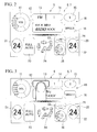
- FIG. 2 shows an example of the icon display screen 9 displayed on the display 6.
- an air conditioner 4 which has a function capable of individually setting the temperatures of a driver's seat and a passenger seat (a so-called dual mode), will be described as an example in this embodiment.
- a volume icon 11, a seek icon 12, a source icon 13, a band icon 14, a preset icon 15, and a play mode icon 16 are displayed on the audio device icon display unit 10 as a plurality of icons. These respective icons are formed of at least characters or figures that respectively represent current set values or current operation modes.
- the volume icon 11 is formed of a figure (for example, a circle graph or the like) that represents the level of current volume.
- the source icon 13 is formed of a character that represents the current source.
- the band icon 14 is formed of a character that represents the currently selected item (a set value or an operation mode).
- the seek icon 12 is formed of characters that represent the currently selected frequency and the currently selected station.
- the preset icon 15 is formed of a character that represents the current preset number.
- the play mode icon 16 is formed of a character that represents the name of the current mode.
- the band icon 14 is associated with the source icon 13. For example, when the current source of the source icon 13 is changed, the display of the character of the selected item of the band icon 14 is also changed according to this source. Meanwhile, when presetting is not yet made, the character of "preset" is displayed in the preset icon 15 (for example, see FIG. 12B ).
- Two set temperature icons 21 and 22, an auto-icon 23, a blowing mode icon 24, a fan speed icon 25, and an inside/outside air icon 26 are displayed on the air conditioner-icon display unit 20.
- These respective icons of the air conditioner-icon display unit 20 are also formed of characters or figures that represent currently selected set values or operation modes.
- the set temperature icons 21 and 22 are formed of characters that represent the current set temperatures.
- the auto-icon 23 is formed of a character that represents the current state of the air conditioner.
- the blowing mode icon 24 is formed of a figure that represents the current blowing port mode.
- the fan speed icon 25 is formed of a figure (for example, a circle graph or the like) that represents the current fan speed.
- the inside/outside air icon 26 is formed of a figure that represents the current intake mode.
- the operation system for vehicle 1 has the above-mentioned configuration.
- the operation of the operation system for vehicle 1 and the respective selection screens, which are displayed when the operations of selecting the respective icons are performed, will be described below with reference to the drawings. Meanwhile, a case where the operation of selecting the source icon 13 of the above-mentioned audio device-icon display unit 10 is performed and a case where the operation of selecting the blowing mode icon 24 of the air conditioner-icon display unit 20 is performed will be described in the description of the operation of the operation system for vehicle 1; and only the displayed selection screens will be described for the operations of other icons.
- the controller 3 detects the position of the operating finger and determines that the source icon 13 corresponding to the position of the operating finger is selected (hereinafter, simply referred to as a selection operation). Then, the controller 3 makes a selection screen 13a for the source icon 13 be displayed and superimposed on the icon display screen 9 of the display 6. As shown in FIGS.
- characters representing respective source names such as "AM”,” FM”, “SATELLITE”, “CD”, “HDD”, and “AUX”, which represent operation modes, are displayed in this order from above on the selection screen 13a; and only the currently selected source name is highlighted by white-and-black inversion or the like. If set values or the names of operation modes can be displayed in one vertical line as described above, a screen is gradually expanded downward from the display position (see FIG. 4 ) of the source icon 13 when display begins and the screen is fully displayed after about 0.3 to 0.4 seconds from the beginning of the display, for example, as the selection screen 12a shown in FIGS. 4 and 5 .
- the source of the audio device 5 is changed to AM.
- the source of the audio device 5 is changed to FM.
- the source of the audio device 5 is changed to SATELLITE RADIO.
- the character of "CD” is selected and operated, the source of the audio device 5 is changed to CD.
- the character of "HDD” is selected, the source of the audio device 5 is changed to HDD.
- the character of "AUX” is selected and operated, the source of the audio device 5 is changed to AUX.
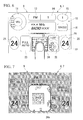
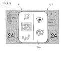
- blowing mode icon 24 of the air conditioner-icon display unit 20 when it is determined that the blowing mode icon 24 of the air conditioner-icon display unit 20 is selected and operated by an operating finger, a selection screen 24a for the blowing mode icon 24 is displayed and superimposed on the icon display screen 9 as shown in FIGS. 6 to 8 .
- blowing modes of the air conditioner 4 are displayed in two lines on the selection screen 24a.
- the blowing modes are a plurality of figures (which corresponding to, for example, a DEF mode, an F/D defroster mode, a VENT mode, a B/L mode, and a FOOT mode) representing which blowing port among a plurality of blowing ports (not shown) air-conditioning air is blown out of.
- a screen is gradually expanded from the currently selected blowing mode as a center (see FIG. 7 ) in all directions when the display begins and the screen is fully displayed after about 0.3 to 0.4 seconds like the above-mentioned selection screen 12a.
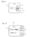
- FIG. 9 shows a selection screen 11a that is displayed when it is determined that the volume icon 11 is selected and operated.
- a character 31 of "MUTE” representing a mute mode, a character 32 of the current volume "24”, and figures of arrows 33 and 34, which are disposed above and below the character 32 and used to increase and decrease volume, are displayed on the selection screen 11a.
- the mode of the audio device 5 is changed to a mute mode by an operation for selecting the character 31 of "MUTE", and volume is increased and decreased by the selection of the arrows 33 and 34.
- FIG. 10 shows a selection screen 12a that is displayed when it is determined that the seek icon 12 is selected and operated.
- a display unit 35 that displays the currently selected received frequency and the name of a radio station and the like corresponding to this received frequency, and figures of an up arrow 36 and a down arrow 37 that are used to detect a receivable frequency from any one side of the high-frequency side or the low-frequency side of the currently received frequency, are displayed on the selection screen 12a.
- a receivable adjacent received frequency is detected by the selection and operation of the up arrow 36 or the down arrow 37 and is set as a received frequency, and the content of this setting is displayed on the display unit 35.
- a set value or an operation mode which is displayed as the band icon 14 by a character or a figure, is switched according to the current set value or operation mode displayed as the source icon 13 by a character or a figure.
- an operation mode "AM” is displayed as the source icon 13
- an operation mode or a set value of an operation item corresponding to "AM” is displayed as the band icon 14.
- the display as the band icon 14 is automatically switched to an operation mode or a set value of an operation item corresponding to "FM" (for example, a set value or an operation mode, which was set the last time, of set values or operation modes displayed on a selection screen 14b to be described below).
- the operation mode of the audio device 5 is switched so as to be the same operation mode as the operation mode displayed as the band icon 14 by the controller 3.
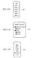
- FIGS. 11A to 11F show selection screens 14a to 14f that are displayed when it is determined that the band icon 14 is selected and operated, respectively, and operation modes are displayed by characters in one vertical line on each of the selection screens. Moreover, the selection screens 14a to 14f are switched according to sources that are selected in the source icon 13.
- the selection screen 14a is displayed. If the band icon 14 is selected and operated when "AM" (radio) is selected in the source icon 13, the selection screen 14b is displayed. If the band icon 14 is selected and operated when "SATELLITE" (satellite radio) is selected in the source icon 13, the selection screen 14c is displayed. In addition, if the band icon 14 is selected and operated when "CD” (compact disc; hereinafter referred to as CD) is selected in the source icon 13, the selection screen 14d is displayed.
- CD compact disc
- the selection screen 14e is displayed. If the band icon 14 is selected and operated when "AUX" (external input) is selected in the source icon 13, the selection screen 14f is displayed.
- HDD hard disk drive
- AM bands “1", “2”, and “TRAFFIC INFORMATION” are displayed as operation modes by characters.
- FM bands “1” and “2” are displayed as operation modes by characters.
- genres of the satellite radio that is, “POPULAR”, “CLASSIC”, “ROCK”, “JAZZ”, and the like are displayed as operation modes by characters.
- disc numbers “DISCI” to “DISC6” of CDs loaded in a CD changer are displayed as operation modes by characters.
- artist names "AAAA”, "BBBB”, and the like stored in folders of a HDD are displayed by genre as operation modes by characters.
- external input lines “LINE1”, “LINE2”, “USB”, “Bluetooth” (registered trademark), and "i-Link” are displayed as operation modes by characters.
- FIG. 12A shows a selection screen 15a displayed when it is determined that the preset icon 15 is selected and operated.
- Preset content (received frequency, station name, and the like) and preset numbers, which have been preset, are displayed on the selection screen 15a.
- the receive channel of the audio device 5 is controlled and changed so that the preset content stored so as to correspond to the preset numbers is received.
- the display shown in FIG. 12B which stimulates presetting, is displayed.
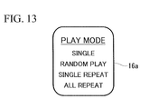
- FIG. 13 shows a selection screen 16a that is displayed when it is determined that the play mode icon 16 is selected and operated. Characters of sound reproducing methods "SINGLE”, “RANDOM PLAY”, “SINGLE REPEAT”, and “ALL REPEAT” are displayed on the selection screen 16a as operation modes. The setting of the play mode of the audio device 5 is changed by the selection and operation of these characters.
- FIGS. 14A and 14B show selection screens 21a and 21b that are displayed when it is determined that the set temperature icon 21 is selected and operated, respectively.
- the selection screen 21a is displayed at the time of a dual mode
- the selection screen 21b is displayed at the time of a single mode.
- a character 41 of "24" which is the current temperature set value (DRIVER TEMP) of the driver's seat
- arrows 42 and 43 used to increase and decrease a temperature set value are displayed above and below the character 41.
- a character 44 of "SINGLE MODE”, which is used to select a single mode, is displayed on the side of the character 41.
- the operation mode of the air conditioner 4 is changed to a single mode from a dual mode by the selection and operation of the character 44.
- the selection screen 21b, which is displayed when a single mode is selected, is a selection screen obtained by omitting the character 44 from the selection screen 21 a.
- FIG. 15A shows a selection screen 22a that is displayed when it is determined that the set temperature icon 22 is selected and operated.
- the selection screen 22a is a screen that is displayed to set the temperature of a passenger seat at the time of a dual mode.
- a character 45 of "24" which is the current temperature set value (PASSENGER TEMP) of the passenger seat, is displayed and arrows 46 and 47 used to increase and decrease a temperature set value are displayed above and below the character 45.
- a character 48 of "DUAL" shown in FIG. 15B is displayed in the set temperature icon 21 at the time of a single mode.
- the operation mode of the air conditioner is changed to a dual mode by the selection and operation of the character 48 of "DUAL". That is, the set temperature icon 21 has a function of changing the operation mode of the air conditioner 4 to a dual mode at the time of a single mode.
- FIG. 16 shows a selection screen 23a that is displayed when it is determined that the auto-icon 23 is selected and operated.
- "FULL AUTO”, "A/C ON”, and "ALL OFF”, which are the operation modes of the air conditioner 4 are displayed on the selection screen 23a by characters.
- the operation mode of the air conditioner is changed to the selected operation mode from the current operation mode by the selection and operation of a certain character among these.
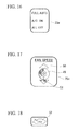
- FIG. 17 shows a selection screen 25a that is displayed when it is determined that the fan speed icon 25 is selected and operated.
- the current air volume (fan speed) which is an operation mode of the air conditioner 4
- the figures of arrows 50 and 51 used to increase and decrease air volume are displayed above and below the circle graph 49. Air volume is increased and decreased by the operation of these arrows 50 and 51.
- FIG. 18 shows a figure 52 of the inside/outside air icon 26 that is displayed when it is determined that the inside/outside air icon 26 is selected and operated in an inside air circulation mode shown in FIG. 2 .
- a figure 53 shown in FIG. 2 is displayed.
- all icons formed of characters or figures, which represent the current set value or the current operation mode of the respective operation items of the air conditioner 4 and the audio device 5, are displayed on one screen of the display 6 as the icon display screen 9.
- a selection screen of an operation mode or a set value of an operation item corresponding to the icon is displayed. Since set values or operation modes can be changed by the selection and operation of set values or operation modes on the selection screen, set values or operation modes can be changed by two times of similar selection and operation of the operation items corresponding to all the icons displayed on the icon display screen 9. As a result, operability is improved, so that it is possible to reduce the burden on a user.
- the icons of the icon display screen 9 are formed of characters or figures that represent the current set values or the current operation modes of the operation items corresponding to the icons, the current set values or the current operation modes of the operation items of all of the air conditioner 4 and the audio device 5 can be confirmed on the icon display screen 9 displayed on one screen of the display 6. For this reason, it is easy to visually check the current set values or the current operation modes as compared to a case where the current set value or the current operation mode is individually displayed for each in-vehicle device as in the related art, and it is possible to improve marketability and to reduce a display space.
- the selection screen is displayed. Accordingly, an operation for changing a set value or an operation mode is performed immediately after the confirmation of the current set value or operation mode. Since an operation for changing an operation mode or a set value of each operation item is intuitively performed in this way, it is possible to reduce the operating time.
- a proximity position where a part of the human body approaches is detected at the time when a distance between the display 6 and a part of the human body becomes equal to or smaller than a predetermined distance is detected by the touch panel 7, and a selection screen corresponding to an icon, which is disposed at the proximity position, is displayed. For this reason, a selection screen is quickly displayed.
- the layout of the selection screen of the operation system for vehicle 1 according to the above-mentioned embodiment is an example, and is not limited to the above-mentioned layout.
- the air conditioner 4 and the audio device 5 have been connected as in-vehicle devices in the operation system for vehicle 1 according to the above-mentioned embodiment, and the configuration, which operates the respective operation items of the air conditioner 4 and the audio device 5, has been described.
- the in-vehicle devices are not limited to the air conditioner 4 and the audio device 5.
- the configuration where an electric seat device changing the position of a seat or a telescopic device and a tilting device changing a steering position are connected so that the respective operation items are operable may be used instead of this configuration.
- the kinds and disposition of icons, which are displayed on the icon display screen 9, may be switched according to in-vehicle devices that are to be connected to the operation system for vehicle 1.
- an operation system for a vehicle capable of reducing the burden on a user by preventing the deterioration of operability caused by operating layers.
Landscapes
- Engineering & Computer Science (AREA)
- Chemical & Material Sciences (AREA)
- Combustion & Propulsion (AREA)
- Transportation (AREA)
- Mechanical Engineering (AREA)
- General Engineering & Computer Science (AREA)
- Theoretical Computer Science (AREA)
- Human Computer Interaction (AREA)
- Physics & Mathematics (AREA)
- General Physics & Mathematics (AREA)
- User Interface Of Digital Computer (AREA)
Abstract
Description
- The present invention relates to an operation system for a vehicle.
Priority is claimed on Japanese Patent Application No.2009-179289, filed July 31, 2009 - An operation system for a vehicle, which operates in-vehicle devices, has been known hitherto. For example, in an operation system for a vehicle disclosed in
Patent Document 1, system changeover switches are always displayed on a main monitor which is a touch panel. Accordingly, it is possible to operate in-vehicle devices, which correspond to the system changeover switches, anytime. -
- Patent Document 1: Japanese Unexamined Patent Application, First Publication No.
2006-96251 - However, in the above-mentioned operation system for a vehicle, it is possible to select devices, which are objects to be operated, by system changeover switches. However, in some cases, it is necessary to perform a touch operation three times or more until the completion of an intended operation. Thus, there is a problem in that the burden on a user is increased due to the deterioration of operability caused by the fact that these operating layers are deep.
- The invention has been made in consideration of the above-mentioned circumstances, and an object of the invention is to provide an operation system for a vehicle that is capable of reducing the burden on a user by preventing the deterioration of operability caused by operating layers.
- The invention employs the following tool in order to achieve the object by solving the above-mentioned problem.
- (1) An operation system for a vehicle according to the invention includes a display unit, a proximity detecting unit that detects that a part of a human body approaches the display unit, a position specifying unit that specifies positions on the display unit where the part of the human body approached on the basis of a detection result of the proximity detecting unit, and a display controlling unit that makes an icon display screen, which displays icons corresponding to respective operation items of a plurality of in-vehicle devices, and a selection screen, which selects set values or operation modes of the operation items corresponding to the icons which are displayed at the positions when the positions are specified by the position specifying unit, are displayed on the display unit, wherein the icons are formed of at least characters or figures representing the set values or the operation modes that are currently selected, and wherein the display controlling unit makes the icon display screen, on which all operable icons are displayed, be displayed on one screen of the display unit..
- According to the operation system for a vehicle described in above-mentioned (1), all icons formed of characters or figures, which represent the current set value or the current operation mode of the operation items of the in-vehicle devices, are displayed on one screen of the display unit as the icon display screen, and a user selects the icon displayed on the icon display screen by a finger or the like. Accordingly, a selection screen of an operation mode or a set value of an operation item corresponding to the icon is displayed. An operation mode or a set value can be changed by the operation selecting the operation mode or the set value on the selection screen.
Furthermore, since the icons are formed of characters or figures that represent the current set values or the current operation modes of the operation items corresponding to the icons, the current set values or the current operation modes of the operation items of all of a plurality of in-vehicle devices can be confirmed on the icon display screen displayed on one screen of the display unit. For this reason, it is easy to visually check the current set values or the current operation modes as compared to a case where the current set values or operation modes are individually displayed for each in-vehicle device as in the related art and there is an effect of improving marketability and reducing display space.
Furthermore, when the icon formed of a character or a figure representing the current set value or operation mode is operated, the selection screen is displayed. Accordingly, since an operation for changing a set value or an operation mode is performed immediately after the confirmation of the current set value or operation mode, an operation for changing an operation mode or a set value of each operation item is intuitively performed. As a result, there is an effect of reducing operating time. - (2) In the operation system for a vehicle described in above-mentioned (1), the display controlling unit may make the selection screen, on which all the operable set values or the operable operation modes are displayed, be displayed on one screen of the display unit.
- In the case of the operation system for a vehicle described in above-mentioned (2), when one icon is selected on the icon display screen, a selection screen where all operable set values or operation modes are displayed is displayed on one screen of the display unit as an operation item corresponding to the icon. For this reason, set values or operation modes of the operation items corresponding to all the icons displayed on the icon display screen can be changed by two times of similar selection. As a result, operability is improved, so that it is possible to reduce the burden on a user.
- (3) In the operation system for a vehicle described in above-mentioned (2), the display controlling unit may reduce the contrast of the icon display screen and may make the selection screen be displayed and superimposed on the icon display screen of which contrast has been reduced, when the selection screen is displayed.
- In the case of the operation system for a vehicle described in above-mentioned (3), by reducing the contrast (for example, switching the display to such as gray-out) of a selection display when the selection screen is displayed and superimposed on the icon display screen, it is possible to easily understand the current operating layer, and therefore it is possible to more intuitively operate an icon. As a result, there is an effect of improving marketability
- (4) In the operation system for a vehicle described in above-mentioned (1), the display controlling unit may switch the set values or the operation modes, which are represented by characters or figures, as a specific icon among the plurality of icons displayed on the icon display screen, according to the current set values or the current operation modes that are displayed in another icon associated with the specific icon.
- In the case of the operation system for a vehicle described in above-mentioned (4), when an operation mode and a set value of the operation item corresponding to another icon are switched, the current set value or operation mode, which is displayed as a specific icon by a character or a figure, is automatically switched according to the operation mode and the set value. For this reason, as compared to a case where an icon is provided for each operation mode or set value of the operation item corresponding to another icon, it is possible to prevent the display from becoming complicated by removing unnecessary icons. As a result, there is an effect of further improving operability.
- (5) In the operation system for a vehicle described in above-mentioned (1), the selection screen may be displayed when the proximity detecting unit detects that a distance between the display unit and the part of the human body becomes equal to or smaller than a predetermined distance.
- In the case of the operation system for a vehicle described in above-mentioned (5), a selection screen is displayed at the time when a distance between the display unit and the part of the human body becomes equal to or smaller than a predetermined distance is detected by the proximity detecting unit. As a result, there is an effect of quickly displaying the selection screen.
- According to the invention, it is possible to provide an operation system for a vehicle that is capable of reducing the burden on a user by preventing the deterioration of operability that is caused by operating layers.
-
-
FIG. 1 is a schematic configuration view of an operation system for a vehicle according to an embodiment of the invention. -
FIG. 2 is a view showing an icon display screen according to the embodiment. -
FIG. 3 is a view showing an operation of selecting a source icon on the icon display screen. -
FIG. 4 is a view showing a screen on which a selection screen corresponding to the source icon is being displayed. -
FIG. 5 is a view showing a screen on which the selection screen has been fully completely displayed. -
FIG. 6 is a view showing an operation for selecting a blowing mode icon according to the embodiment. -
FIG. 7 is a view showing a screen on which a selection screen corresponding to the blowing mode icon being displayed is still on progress. -
FIG. 8 is a view showing a screen on which the selection screen has been fully displayed. -
FIG. 9 is a view showing a selection screen that is displayed when an operation of selecting a volume icon according to the embodiment is performed. -
FIG. 10 is a view showing a selection screen that is displayed when an operation of selecting a seek icon according to the embodiment is performed. -
FIG. 11A is a view showing a selection screen that is displayed when an operation of selecting a band icon according to the embodiment is performed, and is a view showing the selection screen when AM is selected. -
FIG. 11B is a view showing the selection screen, and is a view showing the selection screen when FM is selected. -
FIG. 11C is a view showing the selection screen, and is a view showing the selection screen when SATELLITE RADIO is selected. -
FIG. 11D is a view showing the selection screen, and is a view showing the selection screen when CD is selected. -
FIG. 11E is a view showing the selection screen, and is a view showing the selection screen when HDD is selected. -
FIG. 11F is a view showing the selection screen, and is a view showing the selection screen when external input is selected. -
FIG. 12A is a view showing a selection screen that is displayed when an operation for selecting a preset icon according to the embodiment is performed. -
FIG. 12B is a view showing the selection screen. -
FIG. 13 is a view showing a selection screen that is displayed when an operation of selecting a play mode icon according to the embodiment is performed. -
FIG. 14A is a view showing a selection screen that is displayed when a set temperature icon of a driver's seat according to the embodiment is selected, and is a view showing the selection screen at the time of a dual mode. -
FIG. 14B is a view showing the selection screen, and is a view showing the selection screen at the time of a single mode. -
FIG. 15A is a view showing a selection screen that is displayed when an operation for selecting a set temperature icon for a passenger seat according to the embodiment is performed, and is a view showing the selection screen displayed at the time of a dual mode. -
FIG. 15B is a view showing the selection screen, and is a view showing the set temperature icon for a passenger seat at the time of a single mode. -
FIG. 16 is a view showing a selection screen that is displayed when an auto-icon according to the embodiment is selected. -
FIG. 17 is a view showing a selection screen that is displayed when a fan speed icon according to the embodiment is selected. -
FIG. 18 is a view showing a figure that represents an outside air mode and is displayed when an operation of selecting an inside/outside air icon at the time of an inside air mode according to the embodiment is performed. - An operation system for a vehicle according to an embodiment of the invention will be described below with reference to the drawings.
FIG. 1 shows the schematic configuration of an operation system forvehicle 1 according to the embodiment. The operation system forvehicle 1 includes anoperation unit 2 and a controller (display controlling unit) 3. Anair conditioner 4 and anaudio device 5, which are a plurality of in-vehicle devices, are connected to the operation system forvehicle 1. Each of operation items of theair conditioner 4 and theaudio device 5 can be operated. - The
operation unit 2 is disposed in the vicinity of the steering wheel within easy reach of the driver such as below a display (not shown) for a car navigation system disposed on the dashboard of a vehicle. Theoperation unit 2 includes a display (DISP, display unit) 6 such as a liquid crystal display, and a touch panel (proximity detecting unit, position specifying unit) 7 disposed over the entire area of the display surface of thedisplay 6. - The
display 6 displays an icon display screen 9 (seeFIG. 2 ) according to a control command of thecontroller 3. A plurality of icons (to be described below), which correspond to the respective operation items of theair conditioner 4 and theaudio device 5, for example, the air volume or set temperature of theair conditioner 4, the volume or source of theaudio device 5, and the like, respectively, are disposed on theicon display screen 9 so as to be displayed on one screen of thedisplay 6. Only operable icons among the plurality of icons are displayed on thisdisplay 6. - The
touch panel 7 is an electrostatic capacitive touch panel or the like capable of detecting that a distance between thetouch panel 7 and a part of the human body becomes equal to or smaller than a predetermined distance or a proximity position where a part of the human body approaches. The detection result of thetouch panel 7 is output to thecontroller 3. - The
controller 3 includes an arithmetic unit such as a CPU, and makes theicon display screen 9 be displayed on the above-mentioneddisplay 6 by executing a program stored in a memory 8. Furthermore, thecontroller 3 detects an operation of a user who selects theicon display screen 9. Specifically, thecontroller 3 detects on which icon a user performs an operation for selecting, on the basis of the detection result of thetouch panel 7 and the display position of an icon on theicon display screen 9. - Furthermore, the
controller 3 makes a selection screen (to be described below), on which a set value of an operation item corresponding to an icon subjected to a selection operation or an operation mode of an operation item corresponding to an icon subjected to a selection operation is selected, be displayed and superimposed on theicon display screen 9.
Furthermore, thecontroller 3 detects an operation for changing a set value or an operation mode, which is displayed on the selection screen, on the basis of the detection result of thetouch panel 7. -
FIG. 2 shows an example of theicon display screen 9 displayed on thedisplay 6. An audio device-icon display unit 10, which includes a plurality of icons for the operation of the audio device, is disposed on theicon display screen 9 above the middle position of theicon display screen 9 in a vertical direction, and an air conditioner-icon display unit 20, which includes a plurality of icons for the operation of an air conditioner, is disposed below the middle position of theicon display screen 9 in the vertical direction. Meanwhile, anair conditioner 4, which has a function capable of individually setting the temperatures of a driver's seat and a passenger seat (a so-called dual mode), will be described as an example in this embodiment. - A
volume icon 11, a seekicon 12, asource icon 13, aband icon 14, apreset icon 15, and aplay mode icon 16 are displayed on the audio deviceicon display unit 10 as a plurality of icons. These respective icons are formed of at least characters or figures that respectively represent current set values or current operation modes. Thevolume icon 11 is formed of a figure (for example, a circle graph or the like) that represents the level of current volume. Thesource icon 13 is formed of a character that represents the current source. Theband icon 14 is formed of a character that represents the currently selected item (a set value or an operation mode). The seekicon 12 is formed of characters that represent the currently selected frequency and the currently selected station. Thepreset icon 15 is formed of a character that represents the current preset number. Theplay mode icon 16 is formed of a character that represents the name of the current mode. - Here, the
band icon 14 is associated with thesource icon 13. For example, when the current source of thesource icon 13 is changed, the display of the character of the selected item of theband icon 14 is also changed according to this source. Meanwhile, when presetting is not yet made, the character of "preset" is displayed in the preset icon 15 (for example, seeFIG. 12B ). - Two set
temperature icons icon 23, a blowingmode icon 24, afan speed icon 25, and an inside/outside air icon 26 are displayed on the air conditioner-icon display unit 20. These respective icons of the air conditioner-icon display unit 20 are also formed of characters or figures that represent currently selected set values or operation modes. The settemperature icons icon 23 is formed of a character that represents the current state of the air conditioner. The blowingmode icon 24 is formed of a figure that represents the current blowing port mode. Thefan speed icon 25 is formed of a figure (for example, a circle graph or the like) that represents the current fan speed. The inside/outside air icon 26 is formed of a figure that represents the current intake mode. - The operation system for
vehicle 1 according to this embodiment has the above-mentioned configuration. The operation of the operation system forvehicle 1 and the respective selection screens, which are displayed when the operations of selecting the respective icons are performed, will be described below with reference to the drawings. Meanwhile, a case where the operation of selecting thesource icon 13 of the above-mentioned audio device-icon display unit 10 is performed and a case where the operation of selecting the blowingmode icon 24 of the air conditioner-icon display unit 20 is performed will be described in the description of the operation of the operation system forvehicle 1; and only the displayed selection screens will be described for the operations of other icons. - First, when an operating finger approaches the
source icon 13 displayed on thedisplay 6 as shown inFIG. 3 and a distance between the operating finger and thetouch panel 7 becomes equal to or smaller than a predetermined distance, thecontroller 3 detects the position of the operating finger and determines that thesource icon 13 corresponding to the position of the operating finger is selected (hereinafter, simply referred to as a selection operation). Then, thecontroller 3 makes aselection screen 13a for thesource icon 13 be displayed and superimposed on theicon display screen 9 of thedisplay 6. As shown inFIGS. 4 and 5 , characters representing respective source names, such as "AM"," FM", "SATELLITE", "CD", "HDD", and "AUX", which represent operation modes, are displayed in this order from above on theselection screen 13a; and only the currently selected source name is highlighted by white-and-black inversion or the like. If set values or the names of operation modes can be displayed in one vertical line as described above, a screen is gradually expanded downward from the display position (seeFIG. 4 ) of thesource icon 13 when display begins and the screen is fully displayed after about 0.3 to 0.4 seconds from the beginning of the display, for example, as theselection screen 12a shown inFIGS. 4 and 5 . - Here, when the character of the above-mentioned "AM" is selected and operated, the source of the
audio device 5 is changed to AM. Likewise, when the character of "FM" is selected and operated, the source of theaudio device 5 is changed to FM. Furthermore, when the character of "SATELLITE" is selected and operated, the source of theaudio device 5 is changed to SATELLITE RADIO. When the character of "CD" is selected and operated, the source of theaudio device 5 is changed to CD. When the character of "HDD" is selected, the source of theaudio device 5 is changed to HDD. When the character of "AUX" is selected and operated, the source of theaudio device 5 is changed to AUX. - Furthermore, for example, when the character of "CD" is selected and operated, a control command for switching a source to "CD" from "FM", which is the current source, is output to the
audio device 5 from thecontroller 3. After that, theselection screen 12a disappears after a predetermined time and theicon display screen 9 is displayed alone. Meanwhile, when theselection screen 12a is displayed and superimposed on theicon display screen 9, it is preferable that the contrast of theicon display screen 9 be reduced as shown inFIGS. 4 and 5 (for example, gray-out or the like). - On the other hand, when it is determined that the blowing
mode icon 24 of the air conditioner-icon display unit 20 is selected and operated by an operating finger, aselection screen 24a for the blowingmode icon 24 is displayed and superimposed on theicon display screen 9 as shown inFIGS. 6 to 8 . As shown inFIGS. 7 and8 , blowing modes of theair conditioner 4 are displayed in two lines on theselection screen 24a. The blowing modes are a plurality of figures (which corresponding to, for example, a DEF mode, an F/D defroster mode, a VENT mode, a B/L mode, and a FOOT mode) representing which blowing port among a plurality of blowing ports (not shown) air-conditioning air is blown out of. In a case when the modes are not displayed in one line, a screen is gradually expanded from the currently selected blowing mode as a center (seeFIG. 7 ) in all directions when the display begins and the screen is fully displayed after about 0.3 to 0.4 seconds like the above-mentionedselection screen 12a. - Next, the selection screens of the respective icons will be described. These respective selection screens are displayed and superimposed on the
icon display screen 9 when the respective corresponding icons are selected, like the above-mentionedselection screens -
FIG. 9 shows aselection screen 11a that is displayed when it is determined that thevolume icon 11 is selected and operated. Acharacter 31 of "MUTE" representing a mute mode, acharacter 32 of the current volume "24", and figures ofarrows character 32 and used to increase and decrease volume, are displayed on theselection screen 11a. The mode of theaudio device 5 is changed to a mute mode by an operation for selecting thecharacter 31 of "MUTE", and volume is increased and decreased by the selection of thearrows -
FIG. 10 shows aselection screen 12a that is displayed when it is determined that the seekicon 12 is selected and operated. Adisplay unit 35 that displays the currently selected received frequency and the name of a radio station and the like corresponding to this received frequency, and figures of an uparrow 36 and adown arrow 37 that are used to detect a receivable frequency from any one side of the high-frequency side or the low-frequency side of the currently received frequency, are displayed on theselection screen 12a. A receivable adjacent received frequency is detected by the selection and operation of theup arrow 36 or thedown arrow 37 and is set as a received frequency, and the content of this setting is displayed on thedisplay unit 35. - Meanwhile, a set value or an operation mode, which is displayed as the
band icon 14 by a character or a figure, is switched according to the current set value or operation mode displayed as thesource icon 13 by a character or a figure. For example, when an operation mode "AM" is displayed as thesource icon 13, an operation mode or a set value of an operation item corresponding to "AM" (for example, any one displayed on aselection screen 14a to be described below) is displayed as theband icon 14. After that, when display performed by thesource icon 13 is changed to "FM" from "AM", the display as theband icon 14 is automatically switched to an operation mode or a set value of an operation item corresponding to "FM" (for example, a set value or an operation mode, which was set the last time, of set values or operation modes displayed on aselection screen 14b to be described below). At this time, the operation mode of theaudio device 5 is switched so as to be the same operation mode as the operation mode displayed as theband icon 14 by thecontroller 3. Furthermore, even when the content, which is displayed as thesource icon 13, is changed to "SATELLITE", "CD", "HDD", and "AUX", an operation mode or a set value of an operation item displayed as theband icon 14 is automatically switched like the above-mentioned change to "FM" from "AM". -
FIGS. 11A to 11F show selection screens 14a to 14f that are displayed when it is determined that theband icon 14 is selected and operated, respectively, and operation modes are displayed by characters in one vertical line on each of the selection screens. Moreover, the selection screens 14a to 14f are switched according to sources that are selected in thesource icon 13. - More specifically, if the
band icon 14 is selected and operated when "AM" (radio) is selected in thesource icon 13, theselection screen 14a is displayed. If theband icon 14 is selected and operated when "FM" (radio) is selected in thesource icon 13, theselection screen 14b is displayed. If theband icon 14 is selected and operated when "SATELLITE" (satellite radio) is selected in thesource icon 13, theselection screen 14c is displayed. In addition, if theband icon 14 is selected and operated when "CD" (compact disc; hereinafter referred to as CD) is selected in thesource icon 13, theselection screen 14d is displayed. If theband icon 14 is selected and operated when "HDD" (hard disk drive; hereinafter referred to as HDD) is selected in thesource icon 13, theselection screen 14e is displayed. If theband icon 14 is selected and operated when "AUX" (external input) is selected in thesource icon 13, theselection screen 14f is displayed. - On the
selection screen 14a, AM bands "1", "2", and "TRAFFIC INFORMATION" are displayed as operation modes by characters. On theselection screen 14b, FM bands "1" and "2" are displayed as operation modes by characters.
On theselection screen 14c, genres of the satellite radio, that is, "POPULAR", "CLASSIC", "ROCK", "JAZZ", and the like are displayed as operation modes by characters.
On theselection screen 14d, disc numbers "DISCI" to "DISC6" of CDs loaded in a CD changer (not shown) are displayed as operation modes by characters.
On theselection screen 14e, artist names "AAAA", "BBBB", and the like stored in folders of a HDD are displayed by genre as operation modes by characters.
On theselection screen 14f, external input lines "LINE1", "LINE2", "USB", "Bluetooth" (registered trademark), and "i-Link" are displayed as operation modes by characters. -
FIG. 12A shows aselection screen 15a displayed when it is determined that thepreset icon 15 is selected and operated. Preset content (received frequency, station name, and the like) and preset numbers, which have been preset, are displayed on theselection screen 15a. When a line of the preset numbers is selected and operated on theselection screen 15a by an operating finger, the receive channel of theaudio device 5 is controlled and changed so that the preset content stored so as to correspond to the preset numbers is received. Meanwhile, when nothing is set as preset content, the display shown inFIG. 12B , which stimulates presetting, is displayed. -
FIG. 13 shows aselection screen 16a that is displayed when it is determined that theplay mode icon 16 is selected and operated. Characters of sound reproducing methods "SINGLE", "RANDOM PLAY", "SINGLE REPEAT", and "ALL REPEAT" are displayed on theselection screen 16a as operation modes. The setting of the play mode of theaudio device 5 is changed by the selection and operation of these characters. -
FIGS. 14A and 14B show selection screens 21a and 21b that are displayed when it is determined that theset temperature icon 21 is selected and operated, respectively. Theselection screen 21a is displayed at the time of a dual mode, and theselection screen 21b is displayed at the time of a single mode. On theselection screen 21a, acharacter 41 of "24", which is the current temperature set value (DRIVER TEMP) of the driver's seat, is displayed andarrows character 41. When the set value is increased or decreased by thearrow character 44 of "SINGLE MODE", which is used to select a single mode, is displayed on the side of thecharacter 41. The operation mode of theair conditioner 4 is changed to a single mode from a dual mode by the selection and operation of thecharacter 44. Theselection screen 21b, which is displayed when a single mode is selected, is a selection screen obtained by omitting thecharacter 44 from theselection screen 21 a. - Meanwhile,
FIG. 15A shows aselection screen 22a that is displayed when it is determined that theset temperature icon 22 is selected and operated. Theselection screen 22a is a screen that is displayed to set the temperature of a passenger seat at the time of a dual mode. On theselection screen 22a, acharacter 45 of "24", which is the current temperature set value (PASSENGER TEMP) of the passenger seat, is displayed andarrows character 45. Acharacter 48 of "DUAL" shown inFIG. 15B is displayed in theset temperature icon 21 at the time of a single mode. The operation mode of the air conditioner is changed to a dual mode by the selection and operation of thecharacter 48 of "DUAL". That is, theset temperature icon 21 has a function of changing the operation mode of theair conditioner 4 to a dual mode at the time of a single mode. -
FIG. 16 shows aselection screen 23a that is displayed when it is determined that the auto-icon 23 is selected and operated. "FULL AUTO", "A/C ON", and "ALL OFF", which are the operation modes of theair conditioner 4, are displayed on theselection screen 23a by characters. The operation mode of the air conditioner is changed to the selected operation mode from the current operation mode by the selection and operation of a certain character among these. -
FIG. 17 shows aselection screen 25a that is displayed when it is determined that thefan speed icon 25 is selected and operated. On theselection screen 25a, the current air volume (fan speed), which is an operation mode of theair conditioner 4, is displayed by acircle graph 49 and the figures ofarrows circle graph 49. Air volume is increased and decreased by the operation of thesearrows
FIG. 18 shows a figure 52 of the inside/outside air icon 26 that is displayed when it is determined that the inside/outside air icon 26 is selected and operated in an inside air circulation mode shown inFIG. 2 . When the figure 52 is selected and operated, a figure 53 shown inFIG. 2 is displayed. When only two operation modes are switched as described above, a figure representing the current operation mode displayed on an icon is directly changed and do not go through the selection screen. Meanwhile, a case where the inside/outside air mode is displayed by a figure has been described, but the inside/outside air mode may be displayed by a character. - Accordingly, according to the operation system for
vehicle 1 of the above-mentioned embodiment, all icons formed of characters or figures, which represent the current set value or the current operation mode of the respective operation items of theair conditioner 4 and theaudio device 5, are displayed on one screen of thedisplay 6 as theicon display screen 9. When a user selects an icon displayed on theicon display screen 9 by a finger or the like, a selection screen of an operation mode or a set value of an operation item corresponding to the icon is displayed. Since set values or operation modes can be changed by the selection and operation of set values or operation modes on the selection screen, set values or operation modes can be changed by two times of similar selection and operation of the operation items corresponding to all the icons displayed on theicon display screen 9. As a result, operability is improved, so that it is possible to reduce the burden on a user. - Furthermore, since the icons of the
icon display screen 9 are formed of characters or figures that represent the current set values or the current operation modes of the operation items corresponding to the icons, the current set values or the current operation modes of the operation items of all of theair conditioner 4 and theaudio device 5 can be confirmed on theicon display screen 9 displayed on one screen of thedisplay 6. For this reason, it is easy to visually check the current set values or the current operation modes as compared to a case where the current set value or the current operation mode is individually displayed for each in-vehicle device as in the related art, and it is possible to improve marketability and to reduce a display space. - Furthermore, when the icon formed of a character or a figure representing the current set value or operation mode is operated, the selection screen is displayed. Accordingly, an operation for changing a set value or an operation mode is performed immediately after the confirmation of the current set value or operation mode. Since an operation for changing an operation mode or a set value of each operation item is intuitively performed in this way, it is possible to reduce the operating time.
- Moreover, when a selection screen is displayed and superimposed on the
icon display screen 9, it is possible to easily understand the current operating layer by switching the display such as gray-out through the reduction of contrast. Since it is possible to more intuitively operate an icon in this way, it is possible to further improve marketability. - Furthermore, when a set value and an operation mode are switched by the
source icon 13, the selected items of theband icon 14 are automatically switched. For this reason, as compared to a case where an icon is provided for each selected item, it is possible to prevent display from becoming complicated by removing unnecessary icons and to further improve operability. - Moreover, a proximity position where a part of the human body approaches is detected at the time when a distance between the
display 6 and a part of the human body becomes equal to or smaller than a predetermined distance is detected by thetouch panel 7, and a selection screen corresponding to an icon, which is disposed at the proximity position, is displayed. For this reason, a selection screen is quickly displayed. - Meanwhile, the layout of the selection screen of the operation system for
vehicle 1 according to the above-mentioned embodiment is an example, and is not limited to the above-mentioned layout.
Furthermore, theair conditioner 4 and theaudio device 5 have been connected as in-vehicle devices in the operation system forvehicle 1 according to the above-mentioned embodiment, and the configuration, which operates the respective operation items of theair conditioner 4 and theaudio device 5, has been described. The in-vehicle devices are not limited to theair conditioner 4 and theaudio device 5. For example, the configuration where an electric seat device changing the position of a seat or a telescopic device and a tilting device changing a steering position are connected so that the respective operation items are operable may be used instead of this configuration. Furthermore, the kinds and disposition of icons, which are displayed on theicon display screen 9, may be switched according to in-vehicle devices that are to be connected to the operation system forvehicle 1. - According to the invention, it is possible to provide an operation system for a vehicle capable of reducing the burden on a user by preventing the deterioration of operability caused by operating layers.
-
- 6:
- DISPLAY (DISPLAY UNIT)
- 7:
- TOUCH PANEL (PROXIMITY DETECTING UNIT, POSITION SPECIFYING UNIT)
- 11:
- VOLUME ICON (ICON)
- 12:
- SEEK ICON (ICON)
- 13:
- SOURCE ICON (ICON)
- 14:
- BAND ICON (ICON)
- 15:
- PRESET ICON (ICON)
- 16:
- PLAY MODE ICON (ICON)
- 21, 22:
- SET TEMPERATURE ICON (ICON)
- 23:
- AUTO-ICON (ICON)
- 24:
- BLOWING MODE ICON (ICON)
- 25:
- FAN SPEED ICON (ICON)
- 26:
- INSIDE/OUTSIDE AIR ICON (ICON)
Claims (5)
- An operation system for a vehicle comprising:a display unit;a proximity detecting unit that detects that a part of a human body approaches the display unit;a position specifying unit that specifies positions on the display unit where the part of the human body approached on the basis of a detection result of the proximity detecting unit; anda display controlling unit that makes an icon display screen, which displays icons corresponding to respective operation items of a plurality of in-vehicle devices, and a selection screen, which selects set values or operation modes of the operation items corresponding to the icons which are displayed at the positions when the positions are specified by the position specifying unit, are displayed on the display unit,wherein the icons are formed of at least characters or figures representing the set values or the operation modes that are currently selected, andwherein the display controlling unit makes the icon display screen, on which all operable icons are displayed, be displayed on one screen of the display unit.
- The operation system for the vehicle according to Claim 1,
wherein the display controlling unit makes the selection screen, on which all the operable set values or the operable operation modes are displayed, be displayed on one screen of the display unit. - The operation system for the vehicle according to Claim 2,
wherein the display controlling unit reduces contrast of the icon display screen and makes the selection screen be displayed and superimposed on the icon display screen of which contrast has been reduced, when the selection screen is displayed. - The operation system for the vehicle according to Claim 1,
wherein the display controlling unit switches the set values or the operation modes, which are represented by characters or figures as a specific icon among the plurality of icons displayed on the icon display screen, according to the current set values or the current operation modes that are displayed in another icon associated with the specific icon. - The operation system for the vehicle according to Claim 1,
wherein the selection screen is displayed when the proximity detecting unit detects that a distance between the display unit and the part of the human body becomes equal to or smaller than a predetermined distance.
Applications Claiming Priority (2)
| Application Number | Priority Date | Filing Date | Title |
|---|---|---|---|
| JP2009179289 | 2009-07-31 | ||
| PCT/JP2010/061920 WO2011013514A1 (en) | 2009-07-31 | 2010-07-14 | Operation system for vehicle |
Publications (2)
| Publication Number | Publication Date |
|---|---|
| EP2460694A1 true EP2460694A1 (en) | 2012-06-06 |
| EP2460694A4 EP2460694A4 (en) | 2013-01-23 |
Family
ID=43529172
Family Applications (1)
| Application Number | Title | Priority Date | Filing Date |
|---|---|---|---|
| EP10804260A Ceased EP2460694A4 (en) | 2009-07-31 | 2010-07-14 | DRIVING SYSTEM FOR VEHICLE |
Country Status (5)
| Country | Link |
|---|---|
| US (1) | US20120092251A1 (en) |
| EP (1) | EP2460694A4 (en) |
| JP (1) | JP5232920B2 (en) |
| CN (1) | CN102470806B (en) |
| WO (1) | WO2011013514A1 (en) |
Cited By (2)
| Publication number | Priority date | Publication date | Assignee | Title |
|---|---|---|---|---|
| EP2848447A1 (en) * | 2013-09-12 | 2015-03-18 | Seat, S.A. | Method for displaying and/or handling information in a car |
| EP2960099B1 (en) * | 2014-06-13 | 2021-03-17 | Volkswagen Aktiengesellschaft | User interface and method for adjusting a setting of a means of transport by means of a display unit of a user interface |
Families Citing this family (60)
| Publication number | Priority date | Publication date | Assignee | Title |
|---|---|---|---|---|
| US20130241720A1 (en) * | 2012-03-14 | 2013-09-19 | Christopher P. Ricci | Configurable vehicle console |
| US20130145401A1 (en) | 2011-11-16 | 2013-06-06 | Flextronics Ap, Llc | Music streaming |
| JP2012190183A (en) | 2011-03-09 | 2012-10-04 | Sony Corp | Image processing device, method, and program |
| KR20130097266A (en) * | 2012-02-24 | 2013-09-03 | 삼성전자주식회사 | Method and apparatus for editing contents view in mobile terminal |
| US9098367B2 (en) | 2012-03-14 | 2015-08-04 | Flextronics Ap, Llc | Self-configuring vehicle console application store |
| JP5565450B2 (en) * | 2012-05-22 | 2014-08-06 | パナソニック株式会社 | Input/Output Devices |
| US20140075356A1 (en) * | 2012-09-07 | 2014-03-13 | Service Solutions U.S. Llc | Diagnostic Hub |
| JP5925954B2 (en) * | 2013-02-20 | 2016-05-25 | パナソニック インテレクチュアル プロパティ コーポレーション オブ アメリカPanasonic Intellectual Property Corporation of America | Information terminal control method and program |
| WO2014128785A1 (en) * | 2013-02-20 | 2014-08-28 | パナソニック インテレクチュアル プロパティ コーポレーション オブ アメリカ | Program and method for controlling portable information terminal |
| WO2014128781A1 (en) * | 2013-02-20 | 2014-08-28 | パナソニック インテレクチュアル プロパティ コーポレーション オブ アメリカ | Program and method for controlling portable information terminal |
| CN104350335B (en) * | 2013-02-20 | 2017-10-20 | 松下电器(美国)知识产权公司 | The control method and recording medium of portable information terminal, portable information terminal |
| CN104169658B (en) * | 2013-02-20 | 2017-09-19 | 松下电器(美国)知识产权公司 | The control method and program of portable information terminal |
| KR20140105689A (en) * | 2013-02-23 | 2014-09-02 | 삼성전자주식회사 | Method for providing a feedback in response to user input and terminal implementing the same |
| JP5858059B2 (en) * | 2013-04-02 | 2016-02-10 | 株式会社デンソー | Input device |
| CN205992967U (en) * | 2014-03-19 | 2017-03-01 | 三菱电机株式会社 | remote control |
| JP6265839B2 (en) * | 2014-06-09 | 2018-01-24 | アルパイン株式会社 | INPUT DISPLAY DEVICE, ELECTRONIC DEVICE, ICON DISPLAY METHOD, AND DISPLAY PROGRAM |
| US10788948B2 (en) | 2018-03-07 | 2020-09-29 | Quantum Interface, Llc | Systems, apparatuses, interfaces and implementing methods for displaying and manipulating temporal or sequential objects |
| JP6386920B2 (en) * | 2015-01-15 | 2018-09-05 | 日立ジョンソンコントロールズ空調株式会社 | Air conditioning control terminal and air conditioning system |
| WO2016143613A1 (en) * | 2015-03-09 | 2016-09-15 | シャープ株式会社 | Mirror, in-vehicle operation device, and vehicle |
| JP6429699B2 (en) * | 2015-03-27 | 2018-11-28 | 株式会社ホンダアクセス | Vehicle input system |
| JP2017049788A (en) * | 2015-09-01 | 2017-03-09 | 三菱自動車工業株式会社 | In-vehicle information processing equipment |
| US10692126B2 (en) | 2015-11-17 | 2020-06-23 | Nio Usa, Inc. | Network-based system for selling and servicing cars |
| JP6895222B2 (en) * | 2016-02-25 | 2021-06-30 | 富士通株式会社 | Selection support programs, equipment, and methods |
| CN107303793B (en) * | 2016-04-20 | 2020-01-31 | 斑马网络技术有限公司 | Air conditioner control method and device, control equipment and operating system |
| US20180012197A1 (en) | 2016-07-07 | 2018-01-11 | NextEv USA, Inc. | Battery exchange licensing program based on state of charge of battery pack |
| US9928734B2 (en) | 2016-08-02 | 2018-03-27 | Nio Usa, Inc. | Vehicle-to-pedestrian communication systems |
| US11435888B1 (en) | 2016-09-21 | 2022-09-06 | Apple Inc. | System with position-sensitive electronic device interface |
| US10031523B2 (en) | 2016-11-07 | 2018-07-24 | Nio Usa, Inc. | Method and system for behavioral sharing in autonomous vehicles |
| US10708547B2 (en) | 2016-11-11 | 2020-07-07 | Nio Usa, Inc. | Using vehicle sensor data to monitor environmental and geologic conditions |
| US10410064B2 (en) | 2016-11-11 | 2019-09-10 | Nio Usa, Inc. | System for tracking and identifying vehicles and pedestrians |
| US10694357B2 (en) | 2016-11-11 | 2020-06-23 | Nio Usa, Inc. | Using vehicle sensor data to monitor pedestrian health |
| US10699305B2 (en) | 2016-11-21 | 2020-06-30 | Nio Usa, Inc. | Smart refill assistant for electric vehicles |
| US10249104B2 (en) | 2016-12-06 | 2019-04-02 | Nio Usa, Inc. | Lease observation and event recording |
| US10074223B2 (en) | 2017-01-13 | 2018-09-11 | Nio Usa, Inc. | Secured vehicle for user use only |
| US10471829B2 (en) | 2017-01-16 | 2019-11-12 | Nio Usa, Inc. | Self-destruct zone and autonomous vehicle navigation |
| US10031521B1 (en) | 2017-01-16 | 2018-07-24 | Nio Usa, Inc. | Method and system for using weather information in operation of autonomous vehicles |
| US9984572B1 (en) | 2017-01-16 | 2018-05-29 | Nio Usa, Inc. | Method and system for sharing parking space availability among autonomous vehicles |
| US10464530B2 (en) | 2017-01-17 | 2019-11-05 | Nio Usa, Inc. | Voice biometric pre-purchase enrollment for autonomous vehicles |
| US10286915B2 (en) | 2017-01-17 | 2019-05-14 | Nio Usa, Inc. | Machine learning for personalized driving |
| US10897469B2 (en) | 2017-02-02 | 2021-01-19 | Nio Usa, Inc. | System and method for firewalls between vehicle networks |
| US10234302B2 (en) | 2017-06-27 | 2019-03-19 | Nio Usa, Inc. | Adaptive route and motion planning based on learned external and internal vehicle environment |
| US10710633B2 (en) | 2017-07-14 | 2020-07-14 | Nio Usa, Inc. | Control of complex parking maneuvers and autonomous fuel replenishment of driverless vehicles |
| US10369974B2 (en) | 2017-07-14 | 2019-08-06 | Nio Usa, Inc. | Control and coordination of driverless fuel replenishment for autonomous vehicles |
| US10837790B2 (en) | 2017-08-01 | 2020-11-17 | Nio Usa, Inc. | Productive and accident-free driving modes for a vehicle |
| DE102017214190B4 (en) * | 2017-08-15 | 2025-08-21 | Ford Global Technologies, Llc | Bearing arrangement for a motor vehicle |
| JP6988336B2 (en) * | 2017-09-29 | 2022-01-05 | トヨタ自動車株式会社 | Display controls, methods, and programs |
| KR102354135B1 (en) * | 2017-10-12 | 2022-01-24 | 현대자동차주식회사 | Proximity sensor |
| US10635109B2 (en) | 2017-10-17 | 2020-04-28 | Nio Usa, Inc. | Vehicle path-planner monitor and controller |
| US10935978B2 (en) | 2017-10-30 | 2021-03-02 | Nio Usa, Inc. | Vehicle self-localization using particle filters and visual odometry |
| US10606274B2 (en) | 2017-10-30 | 2020-03-31 | Nio Usa, Inc. | Visual place recognition based self-localization for autonomous vehicles |
| KR20190050485A (en) * | 2017-11-03 | 2019-05-13 | 현대자동차주식회사 | The UI(user interface) management server and UI management server control method |
| US10717412B2 (en) | 2017-11-13 | 2020-07-21 | Nio Usa, Inc. | System and method for controlling a vehicle using secondary access methods |
| US10369966B1 (en) | 2018-05-23 | 2019-08-06 | Nio Usa, Inc. | Controlling access to a vehicle using wireless access devices |
| CN109177682A (en) * | 2018-07-26 | 2019-01-11 | 奇瑞新能源汽车技术有限公司 | A kind of automobile DVD button multiplexing system and method |
| JP7259508B2 (en) * | 2019-04-19 | 2023-04-18 | マツダ株式会社 | VEHICLE OPERATION INPUT DEVICE AND VEHICLE OPERATION INPUT METHOD |
| JP7263899B2 (en) * | 2019-04-19 | 2023-04-25 | マツダ株式会社 | VEHICLE OPERATION INPUT DEVICE AND VEHICLE OPERATION INPUT METHOD |
| US12508904B2 (en) | 2021-06-03 | 2025-12-30 | Nissan Motor Co., Ltd. | Display control apparatus and display control method |
| JP7848531B2 (en) * | 2022-03-17 | 2026-04-21 | 富士フイルムビジネスイノベーション株式会社 | Information processing device and program |
| US20240094867A1 (en) * | 2022-09-19 | 2024-03-21 | Garmin International, Inc. | Cluster icon validation |
| CN121062408A (en) * | 2024-08-16 | 2025-12-05 | 深圳引望智能技术有限公司 | Blowing control method and device and vehicle |
Family Cites Families (16)
| Publication number | Priority date | Publication date | Assignee | Title |
|---|---|---|---|---|
| JP2762450B2 (en) * | 1988-03-23 | 1998-06-04 | 富士ゼロックス株式会社 | Display device for user interface, display method using the device, and recording device |
| US6009355A (en) * | 1997-01-28 | 1999-12-28 | American Calcar Inc. | Multimedia information and control system for automobiles |
| US6809724B1 (en) * | 2000-01-18 | 2004-10-26 | Seiko Epson Corporation | Display apparatus and portable information processing apparatus |
| JP4182769B2 (en) * | 2002-06-21 | 2008-11-19 | アイシン・エィ・ダブリュ株式会社 | Image display device and navigation device |
| JP2005011107A (en) * | 2003-06-19 | 2005-01-13 | Yushin Precision Equipment Co Ltd | Display device |
| JP4385300B2 (en) | 2004-09-30 | 2009-12-16 | マツダ株式会社 | Vehicle information display device |
| JP4630644B2 (en) * | 2004-11-18 | 2011-02-09 | 理想科学工業株式会社 | Image processing apparatus with touch panel |
| JP5194374B2 (en) * | 2006-03-29 | 2013-05-08 | ヤマハ株式会社 | Parameter editing apparatus and signal processing apparatus |
| JP4841359B2 (en) * | 2006-08-21 | 2011-12-21 | アルパイン株式会社 | Display control device |
| US8284165B2 (en) * | 2006-10-13 | 2012-10-09 | Sony Corporation | Information display apparatus with proximity detection performance and information display method using the same |
| JP4849412B2 (en) * | 2007-05-15 | 2012-01-11 | 三菱電機株式会社 | Information input display device |
| JP4900824B2 (en) * | 2007-09-18 | 2012-03-21 | トヨタ自動車株式会社 | Input display device |
| JP2009157563A (en) * | 2007-12-26 | 2009-07-16 | Toshiba Tec Corp | Self-checkout terminal |
| JP4486996B2 (en) | 2008-02-01 | 2010-06-23 | 本田技研工業株式会社 | Body structure |
| US8239087B2 (en) * | 2008-02-14 | 2012-08-07 | Steering Solutions Ip Holding Corporation | Method of operating a vehicle accessory |
| KR101513023B1 (en) * | 2008-03-25 | 2015-04-22 | 엘지전자 주식회사 | A terminal and its information display method |
-
2010
- 2010-07-14 JP JP2011524733A patent/JP5232920B2/en active Active
- 2010-07-14 US US13/378,220 patent/US20120092251A1/en not_active Abandoned
- 2010-07-14 CN CN201080026198.0A patent/CN102470806B/en not_active Expired - Fee Related
- 2010-07-14 EP EP10804260A patent/EP2460694A4/en not_active Ceased
- 2010-07-14 WO PCT/JP2010/061920 patent/WO2011013514A1/en not_active Ceased
Cited By (2)
| Publication number | Priority date | Publication date | Assignee | Title |
|---|---|---|---|---|
| EP2848447A1 (en) * | 2013-09-12 | 2015-03-18 | Seat, S.A. | Method for displaying and/or handling information in a car |
| EP2960099B1 (en) * | 2014-06-13 | 2021-03-17 | Volkswagen Aktiengesellschaft | User interface and method for adjusting a setting of a means of transport by means of a display unit of a user interface |
Also Published As
| Publication number | Publication date |
|---|---|
| JP5232920B2 (en) | 2013-07-10 |
| CN102470806A (en) | 2012-05-23 |
| US20120092251A1 (en) | 2012-04-19 |
| WO2011013514A1 (en) | 2011-02-03 |
| JPWO2011013514A1 (en) | 2013-01-07 |
| EP2460694A4 (en) | 2013-01-23 |
| CN102470806B (en) | 2015-02-18 |
Similar Documents
| Publication | Publication Date | Title |
|---|---|---|
| EP2460694A1 (en) | Operation system for vehicle | |
| KR101166895B1 (en) | Integrated control device for vehicle | |
| US7995038B2 (en) | Software flow control of rotary quad human machine interface | |
| US9361000B2 (en) | Information display device for vehicle | |
| US8818624B2 (en) | Adaptive soft buttons for a vehicle user interface | |
| JP2011081798A (en) | User configurable vehicle user interface | |
| JP2003019927A (en) | In-vehicle display device | |
| JP6653489B2 (en) | Input device and input method | |
| JP2011113345A (en) | In-vehicle display system | |
| US20060092130A1 (en) | Human machine interface for a vehicle including touch sensor | |
| JP2016097928A (en) | Vehicular display control unit | |
| JP4735934B2 (en) | Vehicle information display device | |
| WO2014132564A1 (en) | Search controller and search operation system | |
| KR102385060B1 (en) | Input apparatus and control method of the same | |
| CN100592253C (en) | Vehicular multifunction control system | |
| JP5954156B2 (en) | In-vehicle information processing equipment | |
| JP4501067B2 (en) | Vehicle information display device | |
| US11630564B2 (en) | Information processing device and program | |
| US20200307377A1 (en) | System and method for application interaction on an elongated display screen | |
| JP4899488B2 (en) | Vehicle information display device | |
| JP6050168B2 (en) | Information processing device | |
| JP4512999B2 (en) | Vehicle information display device | |
| CN113733910A (en) | Intelligent interactive control system for motor vehicle | |
| KR20160063451A (en) | Apparatus for monitoring display for vehicle and control method thereof | |
| JP6299565B2 (en) | Operation control device |
Legal Events
| Date | Code | Title | Description |
|---|---|---|---|
| PUAI | Public reference made under article 153(3) epc to a published international application that has entered the european phase |
Free format text: ORIGINAL CODE: 0009012 |
|
| 17P | Request for examination filed |
Effective date: 20111220 |
|
| AK | Designated contracting states |
Kind code of ref document: A1 Designated state(s): AL AT BE BG CH CY CZ DE DK EE ES FI FR GB GR HR HU IE IS IT LI LT LU LV MC MK MT NL NO PL PT RO SE SI SK SM TR |
|
| DAX | Request for extension of the european patent (deleted) | ||
| A4 | Supplementary search report drawn up and despatched |
Effective date: 20121220 |
|
| RIC1 | Information provided on ipc code assigned before grant |
Ipc: G06F 3/023 20060101ALI20121214BHEP Ipc: G06F 3/048 20130101ALI20121214BHEP Ipc: H03M 11/04 20060101ALI20121214BHEP Ipc: B60R 16/02 20060101AFI20121214BHEP Ipc: G06F 3/041 20060101ALI20121214BHEP Ipc: B60R 11/02 20060101ALI20121214BHEP |
|
| 17Q | First examination report despatched |
Effective date: 20130925 |
|
| R17C | First examination report despatched (corrected) |
Effective date: 20130925 |
|
| REG | Reference to a national code |
Ref country code: DE Ref legal event code: R003 |
|
| STAA | Information on the status of an ep patent application or granted ep patent |
Free format text: STATUS: THE APPLICATION HAS BEEN REFUSED |
|
| 18R | Application refused |
Effective date: 20160418 |