EP2459100B1 - Manipulateur ergonomique et semi-automatique et applications aux instruments pour chirurgie mini-invasive - Google Patents
Manipulateur ergonomique et semi-automatique et applications aux instruments pour chirurgie mini-invasive Download PDFInfo
- Publication number
- EP2459100B1 EP2459100B1 EP10745428.2A EP10745428A EP2459100B1 EP 2459100 B1 EP2459100 B1 EP 2459100B1 EP 10745428 A EP10745428 A EP 10745428A EP 2459100 B1 EP2459100 B1 EP 2459100B1
- Authority
- EP
- European Patent Office
- Prior art keywords
- manipulator
- handle
- rotation
- inclination
- tool support
- Prior art date
- Legal status (The legal status is an assumption and is not a legal conclusion. Google has not performed a legal analysis and makes no representation as to the accuracy of the status listed.)
- Not-in-force
Links
Images











Classifications
-
- A—HUMAN NECESSITIES
- A61—MEDICAL OR VETERINARY SCIENCE; HYGIENE
- A61B—DIAGNOSIS; SURGERY; IDENTIFICATION
- A61B34/00—Computer-aided surgery; Manipulators or robots specially adapted for use in surgery
- A61B34/70—Manipulators specially adapted for use in surgery
-
- A—HUMAN NECESSITIES
- A61—MEDICAL OR VETERINARY SCIENCE; HYGIENE
- A61B—DIAGNOSIS; SURGERY; IDENTIFICATION
- A61B17/00—Surgical instruments, devices or methods
- A61B17/28—Surgical forceps
- A61B17/29—Forceps for use in minimally invasive surgery
- A61B17/2909—Handles
-
- A—HUMAN NECESSITIES
- A61—MEDICAL OR VETERINARY SCIENCE; HYGIENE
- A61B—DIAGNOSIS; SURGERY; IDENTIFICATION
- A61B34/00—Computer-aided surgery; Manipulators or robots specially adapted for use in surgery
- A61B34/70—Manipulators specially adapted for use in surgery
- A61B34/74—Manipulators with manual electric input means
-
- A—HUMAN NECESSITIES
- A61—MEDICAL OR VETERINARY SCIENCE; HYGIENE
- A61B—DIAGNOSIS; SURGERY; IDENTIFICATION
- A61B17/00—Surgical instruments, devices or methods
- A61B17/04—Surgical instruments, devices or methods for suturing wounds; Holders or packages for needles or suture materials
- A61B17/06—Needles ; Sutures; Needle-suture combinations; Holders or packages for needles or suture materials
- A61B17/062—Needle manipulators
-
- A—HUMAN NECESSITIES
- A61—MEDICAL OR VETERINARY SCIENCE; HYGIENE
- A61B—DIAGNOSIS; SURGERY; IDENTIFICATION
- A61B17/00—Surgical instruments, devices or methods
- A61B17/34—Trocars; Puncturing needles
- A61B17/3417—Details of tips or shafts, e.g. grooves, expandable, bendable; Multiple coaxial sliding cannulas, e.g. for dilating
- A61B17/3421—Cannulas
-
- A—HUMAN NECESSITIES
- A61—MEDICAL OR VETERINARY SCIENCE; HYGIENE
- A61B—DIAGNOSIS; SURGERY; IDENTIFICATION
- A61B17/00—Surgical instruments, devices or methods
- A61B17/34—Trocars; Puncturing needles
- A61B17/3417—Details of tips or shafts, e.g. grooves, expandable, bendable; Multiple coaxial sliding cannulas, e.g. for dilating
- A61B17/3421—Cannulas
- A61B17/3423—Access ports, e.g. toroid shape introducers for instruments or hands
-
- A—HUMAN NECESSITIES
- A61—MEDICAL OR VETERINARY SCIENCE; HYGIENE
- A61B—DIAGNOSIS; SURGERY; IDENTIFICATION
- A61B17/00—Surgical instruments, devices or methods
- A61B2017/0042—Surgical instruments, devices or methods with special provisions for gripping
- A61B2017/00424—Surgical instruments, devices or methods with special provisions for gripping ergonomic, e.g. fitting in fist
-
- A—HUMAN NECESSITIES
- A61—MEDICAL OR VETERINARY SCIENCE; HYGIENE
- A61B—DIAGNOSIS; SURGERY; IDENTIFICATION
- A61B17/00—Surgical instruments, devices or methods
- A61B17/28—Surgical forceps
- A61B17/29—Forceps for use in minimally invasive surgery
- A61B17/2909—Handles
- A61B2017/291—Handles the position of the handle being adjustable with respect to the shaft
-
- A—HUMAN NECESSITIES
- A61—MEDICAL OR VETERINARY SCIENCE; HYGIENE
- A61B—DIAGNOSIS; SURGERY; IDENTIFICATION
- A61B17/00—Surgical instruments, devices or methods
- A61B17/28—Surgical forceps
- A61B17/29—Forceps for use in minimally invasive surgery
- A61B2017/2926—Details of heads or jaws
- A61B2017/2927—Details of heads or jaws the angular position of the head being adjustable with respect to the shaft
-
- A—HUMAN NECESSITIES
- A61—MEDICAL OR VETERINARY SCIENCE; HYGIENE
- A61B—DIAGNOSIS; SURGERY; IDENTIFICATION
- A61B17/00—Surgical instruments, devices or methods
- A61B17/28—Surgical forceps
- A61B17/29—Forceps for use in minimally invasive surgery
- A61B2017/2926—Details of heads or jaws
- A61B2017/2927—Details of heads or jaws the angular position of the head being adjustable with respect to the shaft
- A61B2017/2929—Details of heads or jaws the angular position of the head being adjustable with respect to the shaft with a head rotatable about the longitudinal axis of the shaft
-
- Y—GENERAL TAGGING OF NEW TECHNOLOGICAL DEVELOPMENTS; GENERAL TAGGING OF CROSS-SECTIONAL TECHNOLOGIES SPANNING OVER SEVERAL SECTIONS OF THE IPC; TECHNICAL SUBJECTS COVERED BY FORMER USPC CROSS-REFERENCE ART COLLECTIONS [XRACs] AND DIGESTS
- Y10—TECHNICAL SUBJECTS COVERED BY FORMER USPC
- Y10T—TECHNICAL SUBJECTS COVERED BY FORMER US CLASSIFICATION
- Y10T74/00—Machine element or mechanism
- Y10T74/20—Control lever and linkage systems
- Y10T74/20207—Multiple controlling elements for single controlled element
- Y10T74/20305—Robotic arm
- Y10T74/20329—Joint between elements
Definitions
- the present invention relates to guiding and handling devices for controlling, from outside an intervention zone, the movements of a handling instrument located inside the intervention zone.
- these guiding and handling devices make it possible to control a surgical instrument in minimally invasive surgery applications performed under endoscopy.
- a master arm operable by an operator, is mechanically completely separated and remote from a slave arm which carries the surgical instrument.
- the slave arm is carried by a support in the vicinity of the operating table.
- the master arm is located at a remote control station, provided with display means, the two stations being connected by display and control signal transmission lines.
- Such a device is particularly complex, expensive and cumbersome, comprising a remote manipulation station for remotely controlling a slave station carrying the surgical instrument.
- the invention relates to portable guidance and manipulation devices in which the surgical instrument is placed at the end of a portable manipulator essentially having a connecting arm with a proximal end and a distal end.
- Portable manipulators are known in which the proximal end of the link arm carries a control unit having a hand-held handle. Control members, mounted on the handle, are adapted to be actuated by at least one finger of the hand holding the handle.
- a work unit is mounted on the distal end of the link arm, and includes a tool support adapted to support a surgical tool.
- the tool carrier is tiltable in the work unit, relative to the link arm, by rotation about a transverse axis of inclination.
- the control members thus make it possible to control the orientation of the tool support in a direction of inclination by rotation about the transverse axis of inclination.
- the control members also make it possible to control the orientation of the inclination direction around the longitudinal axis of the link arm, in order to communicate to the tool a direction that can be selected in a cone about the longitudinal axis of the connecting arm.
- the control members further enable the own rotation of the tool carrier to be controlled around the inclination direction.
- the hand holding the handle can carry the manipulator and hold it in a well-defined position and easily controllable by the operator, who naturally controls the position of the surgical tool.
- the own rotation movements and inclination of the tool support at the end of the manipulator are controlled by the actuation of the control members mounted on the handle, and these control members can be solicited by movements of force and pressure. small amplitude of the fingers of the hand holding the handle, ensuring a good dissociation between the maintenance of the manipulator to fix the position of the surgical tool and the control of the movements of the tool support around its position defined by the position of the manipulator .
- the present invention provides that the movements of own rotation and opening-closing clamp if any are transmitted to the tool support by gears and tubes or shafts housed in the work unit, while the movements of inclination around the transverse axis are transmitted by cables.
- the own rotational movement of the tool support is provided by an inlet tube, driven itself. in rotation by a clean rotation actuator, and carrying a conical end gear which itself rotates a rotary conical bevel gear about a transverse axis and which drives an axial conical pinion integral with the tool carrier.
- This arrangement ensures a large clamping force, useful especially when the clamp is a needle holder.
- the clamp comprises a fixed jaw and a movable jaw: the fixed jaw facilitates the positioning of a needle before closing the movable jaw.
- the tool support comprises a hoop pivotally mounted about a transverse axis on the distal end of the connecting arm and secured to a pulley requested. in rotation by a cable itself solicited by a tilt actuator.
- the second of the control members comprises a first input member whose actuation causes the own rotation of the tool support in a first direction of rotation, and a second input member whose actuation causes the own rotation of the tool support in the second direction of rotation.
- the first of the control members may comprise a third input member whose bias causes a positive increase of the angle of inclination, and a fourth input member whose solicitation causes a negative increase. the angle of inclination.
- the input members of the first and second control members may be of the "all or nothing" type, and may each control the movement of the tool support in a respective direction at a substantially constant speed of rotation.
- the input members are progressive type, each controlling the movement of the tool carrier at a variable speed of rotation between a fast speed and a slow speed. A good compromise is thus achieved between the actuation speed and the accuracy.
- the input members are of the "all or nothing" type step mode going into continuous mode at a faster speed by maintaining stress.
- the first of the control members further comprises a possibility of resetting bias, which brings the tool support in the axis of the support arm. In this way, the operator is given great ease of locating the position, from the neutral position at the end of the link arm.
- the manipulator may advantageously furthermore comprise, on the handle, a gripper control member whose piloting actuates at least one gripper actuator which selectively produces the opening and closing of the gripper. the clamp.
- a gripper control member whose piloting actuates at least one gripper actuator which selectively produces the opening and closing of the gripper. the clamp.
- the gripper control member may comprise in particular a first open gripper position, at least a second clamped closed clamp position, and at least a third clamped closed gripper position.
- an arm rotation actuator can also be provided which realizes the own rotation of the link arm about its longitudinal axis with respect to the handle, said arm rotation actuator being controlled by the third arm member. handle control.
- the manipulator may comprise, between the handle and the link arm, a positioning arm by which the operator can modify and fix the angular and / or spatial position relative to the handle relative to the link arm.
- Such a manipulator 100 generally comprises a control unit 1, a link arm 2, and a work unit 3.
- the control unit 1 is mounted on the proximal end 2a of the link arm 2, while the work unit 3 is mounted on the distal end 2b of the link arm 2.
- the control unit 1 comprises a handle 4 adapted to be held by a hand of an operator, and a control body 10 containing various drive means for producing the appropriate movements in the work unit 3.
- the working unit 3 comprises a tool support 5 adapted to support a tool 6.
- a tool 6 in the form of clamp with two branches 6a and 6b.
- the handle 4 comprises control members, for example a first control member 4a, a second control member 4b, a third control member 4c, and a gripper control member 4d.
- the connecting arm 2 passes through a trocar 7 ensuring the connection and the passage through an opening 8 made in the body wall 9.
- the control unit 1 remains outside the body of the patient, while that the working unit 3 penetrates inside the patient's body to reach the intervention zone where the tool 6 must execute controlled movements from the control unit 1.
- the tool 6 and the tool support 5 are in alignment with the longitudinal axis II of the connecting arm 2.
- the operator can position the work unit accurately in the operative zone by sliding CO of the connecting arm 2 in the trocar 7, and by inclination IN of the connecting arm 2 and the trocar 7 in the opening 8 of the body wall 9.
- FIG. figure 5 a first movement of the tool support 5, namely a tilting movement 12 about a transverse axis of inclination 11, has been illustrated. This movement is obtained by the bias 13 of the first control member 4a of the handle 4 , which controls an inclination actuator housed in the control body 10.
- FIG. figure 17 illustrating the tilt actuator 40a connected to the work unit 3 by a tilt transmission cable 41a shown in FIG. figure 15 .
- FIG 6 which illustrates a second movement of the tool support 5, namely an own rotational movement 14 around the inclination direction II.
- This own rotation movement 14 of the tool support 5 around the inclination direction II is obtained by a biasing of the second control member 4b, which controls one or more inclination actuators housed in the control body 10.
- the generation of own rotation movements 14 may advantageously be achieved, according to the invention, by the biasing of the second control member 4b of the handle 4, which controls a specific rotation actuator 40b housed in the control body 10 ( figure 17 ).
- FIG 7 illustrates another movement of the tool support 5, namely a movement by which the direction of inclination II is oriented around the longitudinal axis II of the connecting arm 2. This orientation movement is illustrated by the arrow 16.
- this orienting movement 16 can be produced either by causing the relative rotation of the connecting arm 2 about its longitudinal axis II with respect to the handle 4, or by manipulation of the handle 4 for a rotation. of the entire manipulator around the longitudinal axis II of the link arm 2.
- the rotation of the connecting arm 2 is obtained by the biasing of the third control member 4c of the handle 4, which controls an arm rotation actuator 40c housed in the control body 10 (FIG. figure 17 ).
- the rotation of the connecting arm 2 can be obtained, as illustrated on the Figures 22 to 24 , providing a relative axial rotation articulation of the handle 4 on the rest of the manipulator, with indexing means of the relative position of the handle 4.
- the handle 4 is mounted on a support of 4f handle itself articulated in relative axial rotation on the control body 10.
- the control body comprises a gripping portion 10a that the operator can urge to produce the relative rotation of the handle 4 and the control body 10 .
- the handle 4 is itself articulated about a handle articulation axis 4e, as shown in FIG. figure 11 .
- the handle 4 comprises a first control member 4a whose bias causes the motorized inclination movement 12 of the tool support 5, a second control member 4b whose bias causes the own rotational movement 14 of the tool support 5 around its tilt direction II, and a third control member 4c to produce the own rotational movement 16 of the link arm 2 about its longitudinal axis II.
- the handle 4 comprises a first control member 4a whose bias causes the motorized inclination movement 12 of the tool support 5, a second control member 4b whose bias causes the own rotational movement 14 of the tool support 5 around its tilt direction II, and a third control member 4c to produce the own rotational movement 16 of the link arm 2 about its longitudinal axis II.
- the handle 4 comprises a clamp control member 4d, providing control of the clamping clamp movement illustrated by the arrow 60.
- the clamping 60 of the clamp can be achieved by the biasing the clamp control member 4d which controls the rotation of a clamp actuator 40d housed in the control unit 10 ( figure 17 ).
- the connecting arm 2 is integral with the control body 10, while the handle 4 is articulated about a hinge axis 4e.
- the own rotational movement 16 is obtained by rotation R ( figure 20 ) of the control unit unit 1 - connecting arm 2, the rotation R being produced by the hand of the operator who holds the handle 4.
- Such a rotation R is illustrated by the following views of the figure 20 .
- the articulation of the handle 4 allows the hand to maintain a correct grip of the handle 4 without excessive movement of the wrist joint, during a sufficient rotation of the manipulator about the longitudinal axis II.
- the other movements of the tool support 5 are obtained in a motorized manner, as in the embodiment of the figure 7 .
- the movement of orientation of the inclination direction II about the longitudinal axis II of the link arm 2 is obtained by biasing the third control member 4c of the handle 4, which drives a second inclination actuator located in the control body 10, which actuator rotates the tool support 5 along a transverse axis concurrent and perpendicular to the transverse axis of inclination 11 and the longitudinal axis II.
- This second transverse axis of articulation is identified by the numeral 20 on the figure 8 , and the rotation is illustrated by the arrow 21.
- the tool 6 can be oriented in all the orientations in a cone covering the distal end 2b of the connecting arm 2.
- the other movements of the tool support 5 are identical to those of the figures 7 and 11 , and are motorized in the same way.
- the figure 12 illustrates a variant in which an elastic compression system 70 is interposed between the trocar 7 and the control body 10, to relieve the operator of a portion of the weight of the manipulator.
- control members 4a-4d can be of the push-button type, the touch-sensitive button, or any other type of device that can be actuated by a finger in a short stroke and a low actuating force. . In this way, the risk of interference between the actuation of the control members and the holding in position of the entire manipulator by the hand carrying the handle 4 is further reduced.
- the second control member 4b comprises a first input member H whose actuation causes the own rotation of the tool support 5 in a first clockwise direction of rotation, and a second input member AH whose actuation causes the own rotation of the tool support 5 in a second anti-clockwise rotation direction.
- the input members H and AH can be two pushbuttons.
- These pushbuttons H and AH can each control the rotation of the tool support 5 at a substantially constant speed of rotation.
- it may be progressive type pushbuttons, each controlling the rotation of the tool support 5 at a variable speed of rotation between a fast speed and a slow speed.
- the first control member 4a it can advantageously be realized in the form of a third input member D whose bias causes a positive increase in the angle of inclination, and a fourth input member G whose solicitation causes a negative increase in the angle of inclination.
- a third input member D whose bias causes a positive increase in the angle of inclination
- a fourth input member G whose solicitation causes a negative increase in the angle of inclination.
- it can be two pushbuttons G and D which control a motor each in a respective direction of rotation, and the engine stops when release buttons G and D.
- the gripper control member 4d it can be produced for example in the form of a ratchet push button, which controls the clamping clamp after a first load bias, and which controls opening gripper following a second biasing support, by driving for that the clamp actuator 40d in one and the other direction of rotation.
- the gripper actuator can be driven with a gripper control member 4d having a first open gripper position, a second gripped closed gripper position, and a third gripped closed gripper position.
- a gripper control member 4d having a first open gripper position, a second gripped closed gripper position, and a third gripped closed gripper position.
- FIGS. 13 and 15 illustrate an embodiment of the work unit 3, in the case of a tool 6 in the form of a clamp having a fixed jaw 6a and a movable jaw 6b about a transverse axis of rotation 6c.
- an axial input shaft 31, coupled to the gripper actuator, is provided, oriented along the longitudinal axis II of the linkage arm 2, carrying a conical pinion gear.
- end 32 which drives a lateral conical pinion gear 33 rotatable about a transverse axis 11 and driving the bevel gear 34 itself mounted at the end of an axially threaded output shaft 36.
- a nut 37 is mounted on the threaded portion of the output shaft 36, and moves axially upon rotation of the output shaft 36 to pivotably engage the movable jaw 6b of the tool 6 about the axis. transverse rotation 6c.
- the clean rotation of the tool 6 around the inclination axis II is ensured by an inlet tube 38 oriented along the longitudinal axis 1-1, itself driven in rotation by the rotation actuator. clean, and integral with a conical end gear 39 which itself drives in rotation a lateral conical pinion 40 rotatable about a transverse axis 11 and which drives a tubular axial conical pinion 41 integral with the tool support 5 ( secured to the fixed jaw 6a in this case).
- the tool 6 is mounted with its fixed jaw 6a in a fixed position on the pinion 41, which itself is rotatably mounted axially in the hoop 50.
- a bearing 42 guides the inlet tube 38 in its rotation around of the axis II in the link arm 2.
- the hoop 50 is pivotally mounted about the transverse axis 11 on the distal end 2b of the connecting arm 2. In its rotation, the hoop 50 is secured to a pulley 43 urged in rotation by a cable 41a, better visible on the figure 15 .
- the tilting actuator 40a of the motor type, produces by its rotation the driving of the cable 41a and the pulley 43, for the inclination of the hoop 50 and the tool support 5 around the axis transverse 11 to a direction of inclination II.
- the own rotation actuator 40b ensures the clean rotation of the tool support 5 around the inclination direction II by driving the inlet tube 38.
- the clamp actuator 40d ensures the clamping of the clamp 6, by rotation of the input shaft 31.
- the tool support 5 is rotatably mounted according to a spherical articulation 55 on the distal end 2b of the connecting arm 2.
- the orientation drive of the tool support 5 is provided by peripheral cables 57, for pivoting in all possible directions of the sphere.
- the transmission of the clamping movement of the clamp 6 is effected by a central cable 56, while the own rotational movement is effected by cardan transmission 58. It may be considered for this purpose the description of the pending French patent application. No. 2,927,011 , which is inserted here for reference.
- the figure 20 illustrates the own rotation movement of the manipulator itself, in the case of an embodiment where the own rotation of the connecting arm 2 is not motorized. Thanks to the articulation of the handle 4, the hand can follow the movements without the fingers are detached from the handle 4, ensuring a sufficient rotation of the manipulator around its longitudinal axis.
- control body 10 and the linking arm 2, integral with each other, are motorized in rotation with respect to the handle 4.
- the handle 4 is driven manually in axial rotation about the axis II by means of an axial articulation and a gripping portion 10a on the control body 10.
- the handle 4 is articulated according to the transverse articulation 4e on a handle support 4f itself mounted to free axial rotation by an axial articulation 4g on the control body 10.
- the axial articulation 4g and the gripping portion 10a form a manual drive member in rotation of the handle 4 relative to the rest of the manipulator about the longitudinal axis II of the connecting arm 2.
- the biasing of the gripping portion 10a is useful for performing the large amplitude rotations for the orientation of the inclination direction II about the axis II.
- the rotations of low amplitude, during the surgical procedure, are performed ergonomically by manual loading of the handle 4 in rotation.
- the handle 4 is secured and fixed on the handle support 4f.
- the hinge 4g is a bearing whose outer ring is integral with the handle support 4 and whose inner ring is integral with the connecting arm 2 and the gripping portion 10a shaped wheel set on the connecting arm 2.
- the gripping portion 10a is directly integral with the control body 10.
- the handle 4 is connected to the control body 10 by a positioning arm 30, which can be used independently of the other features described herein.
- the handle 4 can be oriented differently, or even remote away from the longitudinal axis II of the manipulator, for a more ergonomic grip under certain operating conditions.
- the positioning arm 30 is a semi-rigid rod 5 to 30 cm long, deformable by bending under greater bending or torsional forces than the only forces produced by the weight of the manipulator and the resistance of the treated fabrics by the manipulator.
- the handle 4 can be fixed on the end of the semi-rigid rod 30. Alternatively, it can be articulated along a transverse hinge axis 4e.
- the positioning arm 30 is a rigid rod, carrying at its proximal end the handle 4 with a possible transverse joint 4e, and articulated at its distal end on the control body 10 by a lockable articulation 35.
- the handle 4 may advantageously be rotatably mounted about an articulation axis 4e.
- the hinge axis 4e may be an axis transverse to the longitudinal axis I-I of the connecting arm 2.
- hinge axis 4e for example a longitudinal orientation, or an oblique orientation, each possibility having respective advantages.
- each of the actuators may be for example of the electric motor type, hydraulic cylinder or pneumatic jack. It may be preferred actuators of the electric motor type, especially for the ease of power and control flexibility.
Landscapes
- Health & Medical Sciences (AREA)
- Life Sciences & Earth Sciences (AREA)
- Surgery (AREA)
- Engineering & Computer Science (AREA)
- Medical Informatics (AREA)
- Nuclear Medicine, Radiotherapy & Molecular Imaging (AREA)
- Biomedical Technology (AREA)
- Heart & Thoracic Surgery (AREA)
- Molecular Biology (AREA)
- Animal Behavior & Ethology (AREA)
- General Health & Medical Sciences (AREA)
- Public Health (AREA)
- Veterinary Medicine (AREA)
- Robotics (AREA)
- Ophthalmology & Optometry (AREA)
- Manipulator (AREA)
- Surgical Instruments (AREA)
Description
- La présente invention concerne les dispositifs de guidage et de manipulation permettant de commander, depuis l'extérieur d'une zone d'intervention, les mouvements d'un instrument de manipulation situé à l'intérieur de la zone d'intervention.
- En particulier, ces dispositifs de guidage et de manipulation permettent de commander un instrument chirurgical dans les applications de chirurgie mini-invasive pratiquées sous endoscopie.
- Dans ces applications, il est nécessaire de pouvoir déplacer et commander un instrument chirurgical pour effectuer diverses opérations telles qu'une suture, le serrage d'un noeud, une fine dissection de tissus. Il s'agit alors d'opérations délicates, précises, dans lesquelles les mouvements à réaliser sont complexes.
- On a déjà proposé des dispositifs de guidage et de manipulation par robot télécommandé, par exemple le dispositif décrit dans le document
US 5,797,900 . Dans ce cas, un bras maître, actionnable par un opérateur, est mécaniquement complètement séparé et distant d'un bras esclave qui porte l'instrument chirurgical. Le bras esclave est porté par un support au voisinage de la table d'opération. Le bras maître est situé à un poste de commande distant, muni de moyens de visualisation, les deux postes étant reliés par des lignes de transmission de signaux de visualisation et de commande. Un tel dispositif est particulièrement complexe, onéreux et encombrant, comportant un poste de manipulation distant pour télécommander un poste esclave portant l'instrument chirurgical. - L'invention concerne plus spécialement les dispositifs portatifs de guidage et de manipulation, dans lesquels l'instrument chirurgical est placé en bout d'un manipulateur portable ayant essentiellement un bras de liaison à extrémité proximale et extrémité distale. On connaît des manipulateurs portatifs dans lesquels l'extrémité proximale du bras de liaison porte une unité de commande ayant une poignée apte à être tenue par une main. Des organes de commande, montés sur la poignée, sont aptes à être actionnés par au moins un doigt de la main tenant la poignée. Une unité de travail est montée sur l'extrémité distale du bras de liaison, et comporte un support d'outils apte à supporter un outil chirurgical. Le support d'outils est monté inclinable dans l'unité de travail, par rapport au bras de liaison, par rotation autour d'un axe transversal d'inclinaison. Les organes de commande permettent ainsi de commander l'orientation du support d'outils selon une direction d'inclinaison par rotation autour de l'axe transversal d'inclinaison. Les organes de commande permettent aussi de commander l'orientation de la direction d'inclinaison autour de l'axe longitudinal du bras de liaison, afin de communiquer à l'outil une orientation pouvant être choisie dans un cône autour de l'axe longitudinal du bras de liaison. Les organes de commande permettent en outre de commander la rotation propre du support d'outils autour de la direction d'inclinaison.
- Un tel dispositif portatif est par exemple décrit dans le document
US 2005/0222587 A1 , et comprend : - une unité de commande, ayant une poignée apte à être tenue par une main,
- des organes de commande, montés sur la poignée, et aptes à être actionnés par au moins un doigt de la main tenant la poignée,
- un bras de liaison, s'étendant le long d'un axe longitudinal, ayant une extrémité proximale dans laquelle est montée l'unité de commande, et ayant une extrémité distale,
- une unité de travail, montée sur l'extrémité distale du bras de liaison, et comportant un support d'outils apte à supporter un outil,
- le support d'outils étant monté inclinable dans l'unité de travail, par rapport au bras de liaison, par rotation autour d'un axe transversal d'inclinaison,
- les organes de commande permettant de commander l'inclinaison transversale du support d'outils selon une direction d'inclinaison par rotation autour de l'axe transversal d'inclinaison,
- les organes de commande permettant de commander la rotation propre du support d'outils autour de la direction d'inclinaison ;
- dans sa rotation d'inclinaison transversale, le support d'outils est entraîné par au moins un premier actionneur d'inclinaison piloté par un premier des organes de commande de la poignée,
- dans le mouvement de rotation propre du support d'outils autour de la direction d'inclinaison, le manipulateur est piloté par un second des organes de commande de la poignée, qui commande un ou plusieurs actionneurs,
- dans le mouvement d'orientation de la direction d'inclinaison autour de l'axe longitudinal du bras de liaison, le manipulateur est piloté pour réaliser une rotation autour de l'axe longitudinal par la sollicitation d'un organe d'entraînement motorisé en rotation de la poignée par rapport au reste du manipulateur autour de l'axe longitudinal du bras de liaison.
- Grâce à l'utilisation d'actionneurs pilotés par des organes de commande disposés sur la poignée, la main tenant la poignée peut porter le manipulateur et le tenir en une position bien définie et aisément contrôlable par l'opérateur, qui contrôle naturellement ainsi la position de l'outil chirurgical. Simultanément, les mouvements de rotation propre et d'inclinaison du support d'outils en bout du manipulateur sont commandés par l'actionnement des organes de commande montés sur la poignée, et ces organes de commande peuvent être sollicités par des mouvements de force et d'amplitude faibles des doigts de la main tenant la poignée, assurant une bonne dissociation entre le maintien du manipulateur pour fixer la position de l'outil chirurgical et la commande des mouvements du support d'outils autour de sa position définie par la position du manipulateur.
- Simultanément, les différents mouvements possibles d'orientation de la direction d'inclinaison autour de l'axe longitudinal du bras de liaison permettent de donner à l'outil toutes positions nécessaires dans un cône prolongeant le bras de liaison.
- Il s'avère toutefois qu'avec un tel dispositif, la transmission des différents mouvements du porte-outil est encombrante, notamment par la disposition en cascade de plusieurs articulations le long de l'axe longitudinal, et par le fait qu'aucun moyen n'est indiqué pour réaliser l'ensemble des transmissions de mouvement dans un faible diamètre de partie distale de manipulateur. Un besoin existe donc de concevoir d'autres moyens de transmission assurant simultanément un encombrement réduit et une rigidité suffisante des transmissions qui le nécessitent.
- Pour cela, la présente invention prévoit que les mouvements de rotation propre et d'ouverture-fermeture éventuelle de pince sont transmis au support d'outils par des engrenages et tubes ou arbres logés dans l'unité de travail, tandis que les mouvements d'inclinaison autour de l'axe transversal sont transmis par des câbles.
- Un intérêt des engrenages et tubes ou arbres est d'assurer une transmission d'efforts rigide, pour les mouvements qui nécessitent cette propriété, tandis que la transmission par câbles pour le mouvement d'inclinaison permet de réduire simultanément l'encombrement du dispositif.
- En pratique, on peut avantageusement prévoir que le mouvement de rotation propre du support d'outils est assuré par un tube d'entrée, entraîné lui-même en rotation par un actionneur de rotation propre, et portant un pignon conique d'extrémité qui lui-même entraîne en rotation un pignon conique latéral rotatif autour d'un axe transversal et qui entraîne un pignon conique axial solidaire du support d'outils.
- De même, on peut en outre prévoir que l'outil est une pince, et que :
- un actionneur de pince est couplé à un arbre d'entrée axial orienté le long de l'axe longitudinal du bras de liaison,
- l'arbre d'entrée axial porte un pignon conique d'extrémité qui entraîne un pignon conique latéral rotatif autour d'un axe transversal et entraînant un pignon conique monté en bout d'un arbre de sortie fileté et calé axialement sur lequel est monté un écrou solidaire d'un mors mobile de l'outil.
- Cette disposition permet d'assurer une grande force de serrage, utile en particulier lorsque la pince est un porte-aiguille.
- Dans le cas d'une pince, il est en outre avantageux de prévoir que la pince comporte un mors fixe et un mors mobile : le mors fixe facilite le positionnement d'une aiguille avant de fermer le mors mobile.
- Dans le cas d'un outil en forme de pince, on peut en outre prévoir que le support d'outils comprend un arceau monté pivotant autour d'un axe transversal sur l'extrémité distale du bras de liaison et solidaire d'une poulie sollicitée en rotation par un câble lui-même sollicité par un actionneur d'inclinaison.
- Pour améliorer encore la dissociation entre la commande du mouvement de rotation propre du support d'outils et tous les autres mouvements du support d'outils, et notamment le maintien du manipulateur en position, on peut avantageusement prévoir que le second des organes de commande comprend un premier organe d'entrée dont l'actionnement provoque la rotation propre du support d'outils dans un premier sens de rotation, et un second organe d'entrée dont l'actionnement provoque la rotation propre du support d'outils dans le second sens de rotation. On donne ainsi à l'opérateur une grande facilité d'inclinaison du support d'outils en bout du bras de liaison, par des mouvements naturels des doigts de la main.
- Selon un mode de réalisation avantageux, le premier des organes de commande peut comprendre un troisième organe d'entrée dont la sollicitation provoque une augmentation positive de l'angle d'inclinaison, et un quatrième organe d'entrée dont la sollicitation provoque une augmentation négative de l'angle d'inclinaison.
- Selon une première réalisation, les organes d'entrée des premier et second organes de commande peuvent être de type « tout ou rien », et peuvent piloter chacun le mouvement du support d'outils dans un sens respectif selon une vitesse de rotation sensiblement constante.
- En alternative, on peut prévoir que les organes d'entrée sont de type progressif, pilotant chacun le mouvement du support d'outils selon une vitesse de rotation variable entre une vitesse rapide et une vitesse lente. On réalise ainsi un bon compromis entre la vitesse d'actionnement et la précision.
- De préférence, on pourra prévoir que les organes d'entrée sont de type « tout ou rien » à mode pas à pas se mettant en mode continu à vitesse plus rapide par maintien de sollicitation.
- Plus avantageusement, on peut prévoir que le premier des organes de commande comprend en outre une possibilité de sollicitation de remise à zéro, qui ramène le support d'outils dans l'axe du bras support. De la sorte, on donne à l'opérateur une grande facilité de repérage de la position, à partir de la position neutre en bout du bras de liaison.
- Dans le cas d'un outil de type pince, le manipulateur peut avantageusement comprendre en outre, sur la poignée, un organe de commande de pince dont l'actionnement pilote au moins un actionneur de pince qui produit sélectivement l'ouverture et la fermeture de la pince. Ainsi, l'actionnement de la pince est également réalisé par un mouvement aisé d'un doigt de la main, sans interférence avec le maintien du manipulateur et avec les autres mouvements du support d'outils.
- Dans ce cas, l'organe de commande de pince peut comprendre notamment une première position de pince ouverte, au moins une seconde position de pince fermée à faible serrage, et au moins une troisième position de pince fermée à fort serrage.
- En complément ou en alternative, on peut prévoir en outre un actionneur de rotation de bras réalisant la rotation propre du bras de liaison autour de son axe longitudinal par rapport à la poignée, ledit actionneur de rotation propre de bras étant piloté par le troisième organe de commande de la poignée.
- Selon une autre réalisation avantageuse, le manipulateur peut comprendre, entre la poignée et le bras de liaison, un bras de positionnement par lequel l'opérateur peut modifier et fixer la position angulaire et/ou spatiale relative à la poignée par rapport au bras de liaison.
- D'autres objets, caractéristiques et avantages de la présente invention ressortiront de la description suivante de modes de réalisation particuliers, faite en relation avec les figures jointes, parmi lesquelles :
- la
figure 1 est un schéma de principe illustrant la structure générale d'un manipulateur selon un mode de réalisation de la présente invention, en position d'utilisation ; - la
figure 2 illustre le manipulateur de lafigure 1 , avec la poignée légèrement pivotée ; - la
figure 3 illustre le manipulateur de lafigure 1 , en position pivotée autour du trocart ; - la
figure 4 est une vue schématique du manipulateur de lafigure 3 , avec la poignée pivotée ; - la
figure 5 est une vue générale du manipulateur des figures précédentes, illustrant le mouvement d'inclinaison du support d'outils ; - la
figure 6 illustre le mouvement de rotation propre du support d'outils ; - la
figure 7 illustre un mode de réalisation du manipulateur des figures précédentes, et montre les différents mouvements de l'outil ; - la
figure 8 illustre un autre mode de réalisation pour obtenir les mouvements de l'outil ; - la
figure 9 illustre un autre mode de réalisation pour obtenir les mouvements de l'outil ; - la
figure 10 illustre un autre mode de réalisation pour obtenir les mouvements de l'outil ; - la
figure 11 illustre un mode de réalisation avantageux pour obtenir les mouvements de l'outil ; - la
figure 12 illustre un autre mode de réalisation du manipulateur, avec un moyen élastique de rappel axial entre le trocart et le corps de manipulateur ; - la
figure 13 est une vue de côté en coupe illustrant une unité de travail selon un mode de réalisation de la présente invention ; - la
figure 14 est une vue en perspective illustrant partiellement l'unité de travail selon lafigure 13 ; - la
figure 15 illustre un mode de réalisation des moyens d'entraînement en inclinaison du support d'outils ; - la
figure 16 est une vue en perspective générale d'un manipulateur selon un mode de réalisation de l'invention ; - la
figure 17 est une vue en perspective du manipulateur de lafigure 16 , capot d'unité de commande enlevé ; - la
figure 18 illustre, en vue de côté en coupe, les moyens de transmission des mouvements selon un autre mode de réalisation d'une unité de travail de l'invention ; - la
figure 19 est une vue schématique générale en perspective d'un manipulateur selon le mode de réalisation de l'invention ; - la
figure 20 illustre les étapes d'un mouvement de rotation manuelle du corps de manipulateur à l'aide d'une poignée articulée ; - la
figure 21 illustre, en perspective, les différentes étapes d'un mouvement de rotation propre axial motorisé d'un corps de manipulateur par rapport à la poignée ; - la
figure 22 illustre deux positions angulaires du manipulateur par rapport à la poignée dans un mode de réalisation particulier à moyens manuels d'orientation de la direction d'inclinaison ; - la
figure 23 est une vue partielle de côté en coupe des moyens d'orientation manuels de lafigure 22 ; - la
figure 24 est une vue en perspective des moyens d'orientation manuels selon une variante de l'invention ; - la
figure 25 illustre schématiquement un manipulateur selon un autre mode de réalisation de l'invention, à liaison déformable entre la poignée et le corps de manipulateur ; - la
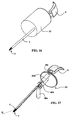
figure 26 illustre un autre mode de réalisation du manipulateur selon l'invention, à liaison articulée entre la poignée et le corps de manipulateur ; et - la
figure 27 illustre un exemple de positionnement d'organes d'entrée sur une poignée. - On considère tout d'abord la structure générale d'un manipulateur selon l'invention, tel qu'illustré sur les
figures 1 à 12 . - Un tel manipulateur 100 comprend de façon générale une unité de commande 1, un bras de liaison 2, et une unité de travail 3.
- L'unité de commande 1 est montée sur l'extrémité proximale 2a du bras de liaison 2, tandis que l'unité de travail 3 est montée sur l'extrémité distale 2b du bras de liaison 2.
- L'unité de commande 1 comprend une poignée 4 apte à être tenue par une main d'un opérateur, et un corps de commande 10 contenant divers moyens d'entraînement pour produire les mouvements appropriés dans l'unité de travail 3.
- L'unité de travail 3 comporte un support d'outils 5 apte à supporter un outil 6. Sur les figures, on a illustré un outil 6 en forme de pince à deux branches 6a et 6b.
- La poignée 4 comporte des organes de commande, par exemple un premier organe de commande 4a, un second organe de commande 4b, un troisième organe de commande 4c, et un organe de commande de pince 4d.
- Comme dans les dispositifs connus, le bras de liaison 2 passe dans un trocart 7 assurant la liaison et le passage dans une ouverture 8 pratiquée dans la paroi corporelle 9. L'unité de commande 1 reste à l'extérieur du corps du patient, tandis que l'unité de travail 3 pénètre à l'intérieur du corps du patient pour atteindre la zone d'intervention où l'outil 6 doit exécuter des mouvements pilotés depuis l'unité de commande 1.
- Sur les
figures 1 à 4 , l'outil 6 et le support d'outils 5 sont en alignement avec l'axe longitudinal I-I du bras de liaison 2. Comme on le voit sur ces figures, l'opérateur peut positionner l'unité de travail de façon précise dans la zone opératoire par coulissement CO du bras de liaison 2 dans le trocart 7, et par inclinaison IN du bras de liaison 2 et du trocart 7 dans l'ouverture 8 de la paroi corporelle 9. - Sur la
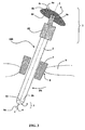
figure 5 , on a illustré un premier mouvement du support d'outils 5 à savoir un mouvement d'inclinaison 12 autour d'un axe transversal d'inclinaison 11. Ce mouvement est obtenu par la sollicitation 13 du premier organe de commande 4a de la poignée 4, qui commande un actionneur d'inclinaison logé dans le corps de commande 10. A titre d'illustration, on pourra se reporter à lafigure 17 , illustrant l'actionneur d'inclinaison 40a, relié à l'unité de travail 3 par un câble de transmission d'inclinaison 41a illustré sur lafigure 15 . - Sur la
figure 5 , par actionnement 13 du premier organe de commande 4a, on a incliné le support d'outils 5 pour l'orienter selon une direction d'inclinaison II. - On considère maintenant la
figure 6 , qui illustre un second mouvement du support d'outils 5, à savoir un mouvement de rotation propre 14 autour de la direction d'inclinaison II. Ce mouvement de rotation propre 14 du support d'outils 5 autour de la direction d'inclinaison II est obtenu par une sollicitation 15 du second organe de commande 4b, qui commande un ou plusieurs actionneurs d'inclinaison logés dans le corps de commande 10. - La génération de mouvements de rotation propre 14 peut avantageusement être réalisée, selon l'invention, par la sollicitation 15 du second organe de commande 4b de la poignée 4, qui commande un actionneur de rotation propre 40b logé dans le corps de commande 10 (
figure 17 ). - On considère maintenant la
figure 7 , qui illustre un autre mouvement du support d'outils 5, à savoir un mouvement par lequel on oriente la direction d'inclinaison II autour de l'axe longitudinal I-I du bras de liaison 2. Ce mouvement d'orientation est illustré par la flèche 16. - Selon l'invention, on peut produire ce mouvement d'orientation 16 soit en provoquant la rotation relative propre du bras de liaison 2 autour de son axe longitudinal I-I par rapport à la poignée 4, soit par une manipulation de la poignée 4 pour une rotation de l'ensemble du manipulateur autour de l'axe longitudinal I-I du bras de liaison 2.
- Dans le premier cas, la rotation du bras de liaison 2 est obtenue par la sollicitation du troisième organe de commande 4c de la poignée 4, qui commande un actionneur de rotation de bras 40c logé dans le corps de commande 10 (
figure 17 ). - En variante de ce premier cas, la rotation du bras de liaison 2 peut être obtenue, comme illustré sur les
figures 22 à 24 , en prévoyant une articulation de rotation axiale relative de la poignée 4 sur le reste du manipulateur, avec des moyens d'indexation de la position relative de la poignée 4. En pratique, on peut prévoir que la poignée 4 est montée sur un support de poignée 4f lui-même articulé en rotation axiale relative sur le corps de commande 10. De préférence le corps de commande comprend une partie de préhension 10a que l'opérateur peut solliciter pour produire la rotation relative de la poignée 4 et du corps de commande 10. - Dans le second cas, pour permettre une rotation axiale aisée de l'ensemble du manipulateur 100 par manipulation de la seule poignée 4, la poignée 4 est elle-même articulée autour d'un axe d'articulation de poignée 4e, comme illustré sur la
figure 11 . - Ainsi, sur la
figure 7 , on a illustré un premier mode de réalisation du manipulateur 100 selon lequel la poignée 4 comporte un premier organe de commande 4a dont la sollicitation provoque le mouvement d'inclinaison motorisé 12 du support d'outils 5, un second organe de commande 4b dont la sollicitation provoque le mouvement de rotation propre 14 du support d'outils 5 autour de sa direction d'inclinaison II, et un troisième organe de commande 4c pour produire le mouvement de rotation propre 16 du bras de liaison 2 autour de son axe longitudinal I-I. De la sorte, on peut orienter l'outil 6 dans toutes les directions d'un cône coiffant l'extrémité distale 2b du bras de liaison 2. - En outre, dans le mode de réalisation de la
figure 7 , l'outil 6 étant une pince, la poignée 4 comporte un organe de commande de pince 4d, assurant la commande du mouvement de serrage de pince illustré par la flèche 60. En pratique, le serrage 60 de la pince peut être réalisé par la sollicitation de l'organe de commande de pince 4d qui commande la rotation d'un actionneur de pince 40d logé dans l'unité de commande 10 (figure 17 ). - Selon la variante illustrée sur la
figure 11 , le bras de liaison 2 est solidaire du corps de commande 10, tandis que la poignée 4 est articulée autour d'un axe d'articulation 4e. Dans ce cas, le mouvement de rotation propre 16 est obtenu par rotation R (figure 20 ) de l'ensemble unité de commande 1 - bras de liaison 2, la rotation R étant produite par la main de l'opérateur qui tient la poignée 4. Une telle rotation R est illustrée par la suite des vues de lafigure 20 . L'articulation de la poignée 4 permet à la main de conserver une prise correcte de la poignée 4 sans mouvement exagéré de l'articulation du poignet, pendant une rotation suffisante du manipulateur autour de l'axe longitudinal I-I. Les autres mouvements du support d'outils 5 sont obtenus de façon motorisée, comme dans le mode de réalisation de lafigure 7 . - Dans le mode de réalisation de la
figure 8 , le mouvement d'orientation de la direction d'inclinaison II autour de l'axe longitudinal I-I du bras de liaison 2 est obtenu par sollicitation du troisième organe de commande 4c de la poignée 4, qui pilote un second actionneur d'inclinaison situé dans le corps de commande 10, lequel actionneur entraîne en rotation le support d'outils 5 selon un axe transversal concourant et perpendiculaire à l'axe transversal d'inclinaison 11 et à l'axe longitudinal I-I. Ce second axe transversal d'articulation est repéré par la référence numérique 20 sur lafigure 8 , et la rotation est illustrée par la flèche 21. - Ainsi, par combinaison des deux rotations d'inclinaison autour des axes 11 et 20, on peut orienter l'outil 6 dans toutes les orientations dans un cône coiffant l'extrémité distale 2b du bras de liaison 2.
- Les autres mouvements du support d'outils 5 sont identiques à ceux des
figures 7 et11 , et sont motorisés de la même façon. - Dans le mode de réalisation illustré sur la
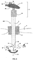
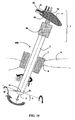
figure 9 , on retrouve le premier mouvement d'inclinaison 12 autour de l'axe transversal d'inclinaison 11, le mouvement de serrage de pince 60 pour l'outil 6, le second mouvement d'inclinaison par rotation 21 autour d'un second axe transversal 20 concourant, et le mouvement de rotation propre 16 du bras de liaison 2 autour de son axe longitudinal I-I. Dans ce cas, il n'est pas indispensable de prévoir d'autres moyens pour assurer la rotation propre de l'outil 6 autour de sa direction d'inclinaison II, car ce mouvement peut être réalisé par combinaison synchrone des rotations autour des axes 11, 20 et I-I. - Toutefois, un mouvement de rotation propre de l'outil 6 autour de son axe d'inclinaison II peut avantageusement être ajouté, comme illustré sur la
figure 10 . - La
figure 12 illustre une variante dans laquelle un système élastique 70 de compression est interposé entre le trocart 7 et le corps de commande 10, pour soulager l'opérateur d'une partie du poids du manipulateur. - Dans tous les modes de réalisation décrits ci-dessus, les organes de commandes 4a-4d peuvent être de type bouton-poussoir, bouton tactile, ou tout autre type de dispositif actionnable par un doigt selon une faible course et une faible force d'actionnement. De la sorte, on réduit encore le risque d'interférence entre l'actionnement des organes de commandes et le maintien en position de l'ensemble du manipulateur par la main qui porte la poignée 4.
- Selon un mode de réalisation avantageux, illustré par la
figure 27 , le second organe de commande 4b comprend un premier organe d'entrée H dont l'actionnement provoque la rotation propre du support d'outils 5 dans un premier sens horaire de rotation, et un second organe d'entrée AH dont l'actionnement provoque la rotation propre du support d'outils 5 dans un second sens anti-horaire de rotation. Par exemple, les organes d'entrée H et AH peuvent être deux boutons-poussoirs. - Ces boutons-poussoirs H et AH peuvent piloter chacun la rotation du support d'outils 5 selon une vitesse de rotation sensiblement constante.
- En alternative, il peut s'agir de boutons-poussoirs de type progressifs, pilotant chacun la rotation du support d'outils 5 selon une vitesse de rotation variable entre une vitesse rapide et une vitesse lente.
- Selon une autre possibilité plus avantageuse, permettant notamment de raccourcir les étapes préparatoires de conformation du manipulateur avant un geste opératoire, il peut s'agir de boutons-poussoirs de type « tout ou rien » à mode pas à pas se mettant en mode continu à vitesse plus rapide en cas de maintien de sollicitation.
- En ce qui concerne le premier organe de commande 4a, on peut avantageusement le réaliser sous forme d'un troisième organe d'entrée D dont la sollicitation provoque une augmentation positive de l'angle d'inclinaison, et un quatrième organe d'entrée G dont la sollicitation provoque une augmentation négative de l'angle d'inclinaison. Par exemple, il peut s'agir de deux boutons-poussoirs G et D qui pilotent un moteur chacun dans un sens de rotation respectif, et le moteur s'arrête lorsqu'on relâche les boutons G et D.
- Avantageusement, on peut en outre prévoir une possibilité de sollicitation de remise à zéro rapide, qui ramène le support d'outils 5 dans l'axe du bras de liaison 2, par exemple si l'on appuie sur les deux boutons-poussoirs G et D simultanément.
- Quant à l'organe de commande de pince 4d, on peut le réaliser par exemple sous forme d'un bouton-poussoir à cliquet, qui commande le serrage de pince à la suite d'une première sollicitation d'appui, et qui commande l'ouverture de pince à la suite d'une seconde sollicitation d'appui, en pilotant pour cela l'actionneur de pince 40d dans l'un et l'autre des sens de rotation.
- Avantageusement, on peut piloter l'actionneur de pince avec un organe de commande de pince 4d ayant une première position de pince ouverte, une seconde position de pince fermée à faible serrage, et une troisième position de pince fermée à fort serrage. Cela permet à l'opérateur, par exemple, de disposer une aiguille dans la pince, de piloter le faible serrage, de parfaire le positionnement de l'aiguille par glissement dans la pince, puis de bloquer l'aiguille en pilotant le fort serrage.
- On considère maintenant les
figures 13 et15 , qui illustrent un mode de réalisation de l'unité de travail 3, dans le cas d'un outil 6 en forme de pince ayant un mors fixe 6a et un mors mobile 6b autour d'un axe de rotation transversal 6c. - Pour le mouvement de serrage ou desserrage de la pince 6, on prévoit un arbre d'entrée 31 axial, couplé à l'actionneur de pince, orienté le long de l'axe longitudinal I-I du bras de liaison 2, portant un pignon conique d'extrémité 32 qui entraîne un pignon conique latéral 33 rotatif autour d'un axe transversal 11 et entraînant le pignon conique 34 lui-même monté en bout d'un arbre de sortie 36 fileté et calé axialement. Un écrou 37 est monté sur la partie fileté de l'arbre de sortie 36, et se déplace axialement lors de la rotation de l'arbre de sortie 36 pour entraîner en pivotement le mors mobile 6b de l'outil 6 autour de l'axe de rotation transversal 6c.
- La rotation propre de l'outil 6 autour de l'axe d'inclinaison II est assurée par un tube d'entrée 38 orienté le long de l'axe longitudinal 1-1, entraîné lui-même en rotation par l'actionneur de rotation propre, et solidaire d'un pignon conique d'extrémité 39 qui lui-même entraîne en rotation un pignon conique latéral 40 rotatif autour d'un axe transversal 11 et qui entraîne un pignon conique axial 41 tubulaire solidaire du support d'outils 5 (solidaire du mors fixe 6a dans le cas présent). Autrement dit, l'outil 6 est monté avec son mors fixe 6a en position fixe sur le pignon 41, qui lui-même est monté rotatif axialement dans l'arceau 50. Un coussinet 42 guide le tube d'entrée 38 dans sa rotation autour de l'axe I-I dans le bras de liaison 2.
- L'arceau 50 est monté pivotant autour de l'axe transversal 11 sur l'extrémité distale 2b du bras de liaison 2. Dans sa rotation, l'arceau 50 est solidaire d'une poulie 43 sollicitée en rotation par un câble 41 a, mieux visible sur la
figure 15 . - Comme on le distingue sur les
figures 15 et17 , l'actionneur d'inclinaison 40a, de type moteur, produit par sa rotation l'entraînement du câble 41a et de la poulie 43, pour l'inclinaison de l'arceau 50 et du support d'outils 5 autour de l'axe transversal 11 jusqu'à une direction d'inclinaison II. - L'actionneur de rotation propre 40b assure la rotation propre du support d'outils 5 autour de la direction d'inclinaison II par entraînement du tube d'entrée 38. L'actionneur de pince 40d assure le serrage de la pince 6, par rotation de l'arbre d'entrée 31.
- Sur la
figure 17 , on a en outre représenté un actionneur de rotation de bras 40c apte à provoquer la rotation de l'ensemble du manipulateur autour de la poignée 4. - Dans la réalisation illustrée sur la
figure 18 , le support d'outils 5 est monté rotatif selon une articulation sphérique 55 sur l'extrémité distale 2b du bras de liaison 2. L'entraînement en orientation du support d'outils 5 est assuré par des câbles périphériques 57, pour un pivotement dans toutes les orientations possibles de la sphère. - La transmission du mouvement de serrage de la pince 6 s'effectue par un câble central 56, tandis que le mouvement de rotation propre s'effectue par une transmission par cardan 58. On pourra pour cela considérer la description de la demande de brevet français pendante N°
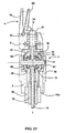
2 927 011 - Sur la
figure 19 , on distingue l'ensemble du manipulateur selon ce mode de réalisation, avec des câbles pour la transmission des mouvements. - La
figure 20 illustre le mouvement de rotation propre du manipulateur lui-même, dans le cas d'un mode de réalisation où la rotation propre du bras de liaison 2 n'est pas motorisée. Grâce à l'articulation de la poignée 4, la main peut suivre les mouvements sans que les doigts se détachent de la poignée 4, en assurant une rotation suffisante du manipulateur autour de son axe longitudinal. - Sur les
figures 21 et17 , on a illustré le mode de réalisation où le corps de commande 10 et le bras de liaison 2, solidaires l'un de l'autre, sont motorisés en rotation par rapport à la poignée 4. - Sur la
figure 22 , la poignée 4 est entraînée manuellement en rotation axiale autour de l'axe I-I grâce à une articulation axiale et une partie de préhension 10a sur le corps de commande 10. En pratique, la poignée 4 est articulée selon l'articulation transversale 4e sur un support de poignée 4f lui-même monté à rotation axiale libre par une articulation axiale 4g sur le corps de commande 10. - L'articulation axiale 4g et la partie de préhension 10a forment un organe d'entraînement manuel en rotation de la poignée 4 par rapport au reste du manipulateur autour de l'axe longitudinal I-I du bras de liaison 2. La sollicitation de la partie de préhension 10a, par un doigt de la main tenant la poignée 4, ou par une autre main, est utile pour réaliser les rotations de grande amplitude pour l'orientation de la direction d'inclinaison II autour de l'axe I-I. Les rotations de faible amplitude, au cours du geste opératoire, sont réalisées de façon ergonomique par sollicitation manuelle de la poignée 4 en rotation.
- Dans la variante illustrée sur la
figure 23 , la poignée 4 est solidaire et fixe sur le support de poignée 4f. L'articulation 4g est un roulement dont la bague extérieure est solidaire du support de poignée 4 et dont la bague intérieure est solidaire du bras de liaison 2 et de la partie de préhension 10a en forme de molette calée sur le bras de liaison 2. - En alternative, dans la variante illustrée sur la
figure 24 , la partie de préhension 10a est directement solidaire du corps de commande 10. - Sur les
figures 25 et 26 , la poignée 4 est reliée au corps de commande 10 par un bras de positionnement 30, qui peut être utilisé indépendamment des autres caractéristiques décrites ici. Par ce bras de positionnement 30, la poignée 4 peut être orientée différemment, ou même déportée à l'écart de l'axe longitudinal I-I du manipulateur, pour une préhension plus ergonomique dans certaines conditions opératoires. - Sur la
figure 25 , le bras de positionnement 30 est une tige semi-rigide de 5 à 30 cm de long, déformable par flexion sous des forces de flexion ou de torsion plus importantes que les seules forces produites par le poids du manipulateur et la résistance des tissus traités par le manipulateur. La poignée 4 peut être fixe sur l'extrémité de la tige semi-rigide 30. En alternative, elle peut être articulée selon un axe d'articulation transversal 4e. - Sur la
figure 26 , le bras de positionnement 30 est une tige rigide, portant à son extrémité proximale la poignée 4 avec une éventuelle articulation transversale 4e, et articulé à son extrémité distale sur le corps de commande 10 par une articulation blocable 35. - Comme on l'a décrit dans certains modes de réalisation précédents, la poignée 4 peut avantageusement être montée libre en rotation autour d'un axe d'articulation 4e.
- Par exemple, l'axe d'articulation 4e peut être un axe transversal par rapport à l'axe longitudinal I-I du bras de liaison 2.
- On peut toutefois prévoir d'autres orientations de l'axe d'articulation 4e, par exemple une orientation longitudinale, ou une orientation oblique, chaque possibilité présentant des avantages respectifs.
- Dans tous les modes de réalisation, chacun des actionneurs peut être par exemple de type moteur électrique, vérin hydraulique ou vérin pneumatique. On pourra préférer des actionneurs de type moteur électrique, notamment pour la facilité d'alimentation et la souplesse de commande.
- La présente invention n'est pas limitée aux modes de réalisation qui ont été explicitement décrits, mais elle en inclut les diverses variantes et généralisations contenues dans le domaine des revendications ci-après.
Claims (17)
- Manipulateur comprenant,- une unité de commande (1), ayant une poignée (4) apte à être tenue par une main,- des organes de commande (4a-4d), montés sur la poignée (4), et aptes à être actionnés par au moins un doigt de la main tenant la poignée (4),- un bras de liaison (2), s'étendant le long d'un axe longitudinal (I-I), ayant une extrémité proximale (2a) dans laquelle est montée l'unité de commande (1), et ayant une extrémité distale (2b),- une unité de travail (3), montée sur l'extrémité distale (2b) du bras de liaison (2), et comportant un support d'outils (5) apte à supporter un outil (6),- le support d'outils (5) étant monté inclinable dans l'unité de travail (3), par rapport au bras de liaison (2), par rotation autour d'un axe transversal d'inclinaison (11),- les organes de commande (4a-4d) permettant de commander l'inclinaison (12) transversale du support d'outils (5) selon une direction d'inclinaison (II) par rotation autour de l'axe transversal d'inclinaison (11),- les organes de commande (4a-4d) permettant de commander la rotation propre (14) du support d'outils (5) autour de la direction d'inclinaison (II),et dans lequel :- dans sa rotation d'inclinaison (12) transversale, le support d'outils (5) est entraîné par au moins un premier actionneur d'inclinaison (40a) piloté par un premier (4a) des organes de commande de la poignée (4),- dans le mouvement de rotation propre (14) du support d'outils (5) autour de la direction d'inclinaison (II), le manipulateur est piloté par un second (4b) des organes de commande de la poignée (4), qui commande un ou plusieurs actionneurs (40b),caractérisé en ce que les mouvements de rotation propre (14) et d'ouverture-fermeture (60) éventuelle d'outil (6) sont transmis au support d'outils (5) par des engrenages (39, 40, 41 ; 32, 33, 34) et tubes (38, 41) ou arbres (31, 36) logés dans l'unité de travail (3), tandis que les mouvements d'inclinaison autour de l'axe transversal d'inclinaison (11) sont transmis par des câbles (41 a).
- Manipulateur selon la revendication 1, caractérisé en ce que le mouvement de rotation propre (14) du support d'outils (5) est assuré par un tube d'entrée (38) orienté le long de l'axe longitudinal (I-I), entraîné lui-même en rotation par un actionneur (40b) de rotation propre, et portant un pignon conique d'extrémité (39) qui lui-même entraîne en rotation un pignon conique latéral (40) rotatif autour d'un axe transversal (11) et qui entraîne un pignon conique axial (41) solidaire du support d'outils (5).
- Manipulateur selon l'une des revendications 1 ou 2, dans lequel l'outil (6) est une pince, caractérisé en ce que :- un actionneur de pince est couplé à un arbre d'entrée axial (31) orienté le long de l'axe longitudinal (I-I) du bras de liaison (2),- l'arbre d'entrée axial (31) porte un pignon conique d'extrémité (32) qui entraîne un pignon conique latéral (33) rotatif autour d'un axe transversal (11) et entraînant un pignon conique (34) monté en bout d'un arbre de sortie (36) fileté et calé axialement sur lequel est monté un écrou (37) solidaire d'un mors mobile (6b) de l'outil (6).
- Manipulateur selon la revendication 3, caractérisé en ce que la pince comprend un mors fixe (6a) et un mors mobile (6b).
- Manipulateur selon l'une quelconque des revendications 1 à 4, caractérisé en ce que le support d'outils (5) comprend un arceau (50) monté pivotant autour d'un axe transversal (11) sur l'extrémité distale (2b) du bras de liaison (2) et solidaire d'une poulie (43) sollicitée en rotation par un câble (41a) lui-même sollicité par un actionneur d'inclinaison (40a).
- Manipulateur selon l'une quelconque des revendications 1 à 5, caractérisé en ce que le second (4b) des organes de commande comprend un premier organe d'entrée (H) dont l'actionnement provoque la rotation propre du support d'outils (5) dans un premier sens de rotation, et un second organe d'entrée (AH) dont l'actionnement provoque la rotation propre du support d'outils (5) dans le second sens de rotation.
- Manipulateur selon l'une quelconque des revendications 1 à 6, caractérisé en ce que le premier (4a) des organes de commande comprend un troisième organe d'entrée (D) dont la sollicitation provoque une augmentation positive de l'angle d'inclinaison, et un quatrième organe d'entrée (G) dont la sollicitation provoque une augmentation négative de l'angle d'inclinaison.
- Manipulateur selon l'une des revendications 6 ou 7, caractérisé en ce que les organes d'entrée sont de type « tout ou rien », et pilotent chacun le mouvement du support d'outils (5) dans un sens respectif selon une vitesse de rotation sensiblement constante.
- Manipulateur selon l'une des revendications 6 ou 7, caractérisé en ce que les organes d'entrée sont de type progressif, pilotant chacun le mouvement du support d'outils (5) selon une vitesse de rotation variable entre une vitesse rapide et une vitesse lente.
- Manipulateur selon l'une des revendications 6 ou 7, caractérisé en ce que les organes d'entrée sont de type « tout ou rien » à mode pas à pas se mettant en mode continu à vitesse plus rapide par maintien de sollicitation.
- Manipulateur selon la revendication 7, caractérisé en ce que le premier (4a) des organes de commande comprend en outre une possibilité de sollicitation de remise à zéro, qui ramène le support d'outils (5) dans l'axe du bras support.
- Manipulateur selon l'une quelconque des revendications 1 à 11, caractérisé en ce que, dans le cas d'un outil (6) de type pince, le manipulateur comprend en outre, sur la poignée (4), un organe de commande de pince (4d) dont l'actionnement pilote au moins un actionneur de pince (40d).
- Manipulateur selon la revendication 12, caractérisé en ce que l'organe de commande de pince (4d) comprend une première position de pince ouverte, au moins une seconde position de pince fermée à faible serrage, et au moins une troisième position de pince fermée à fort serrage.
- Manipulateur selon l'une quelconque des revendications 1 à 13, caractérisé en ce qu'il comprend un actionneur de rotation de bras (40c) réalisant la rotation propre du bras de liaison (2) autour de son axe longitudinal (I-I) par rapport à la poignée (4), et réalisant ainsi un mouvement d'orientation (16) de la direction d'inclinaison (II) autour de l'axe longitudinal (I-I) du bras de liaison (2), ledit actionneur de rotation de bras étant piloté par le troisième organe de commande (4c) de la poignée (4).
- Manipulateur selon l'une quelconque des revendications 1 à 13, caractérisé en ce qu'il comprend une articulation axiale (4g) entre le bras de liaison (2) et la poignée (4), et une partie de préhension (10a) telle qu'une molette solidaire du bras de liaison (2) ou du corps de commande (10), constituant un organe d'entraînement de la poignée (4) par rapport au reste du manipulateur pour réaliser un mouvement d'orientation (16) de la direction d'inclinaison (II) autour de l'axe longitudinal (I-I) du bras de liaison (2).
- Manipulateur selon l'une quelconque des revendications 1 à 13 et 15, caractérisé en ce que la poignée (4) est articulée autour d'un axe d'articulation de poignée (4e).
- Manipulateur selon l'une quelconque des revendications 1 à 14, caractérisé en ce qu'il comprend, entre la poignée (4) et le bras de liaison (2), un bras de positionnement (30) par lequel l'opérateur peut modifier et fixer la position angulaire et/ou spatiale relative à la poignée (4) par rapport au bras de liaison (2).
Applications Claiming Priority (2)
| Application Number | Priority Date | Filing Date | Title |
|---|---|---|---|
| FR0955382A FR2948594B1 (fr) | 2009-07-31 | 2009-07-31 | Manipulateur ergonomique et semi-automatique et applications aux instruments pour chirurgie mini-invasive |
| PCT/IB2010/053477 WO2011013103A1 (fr) | 2009-07-31 | 2010-07-30 | Manipulateur ergonomique et semi-automatique et applications aux instruments pour chirurgie mini-invasive |
Publications (2)
| Publication Number | Publication Date |
|---|---|
| EP2459100A1 EP2459100A1 (fr) | 2012-06-06 |
| EP2459100B1 true EP2459100B1 (fr) | 2014-03-12 |
Family
ID=42102400
Family Applications (1)
| Application Number | Title | Priority Date | Filing Date |
|---|---|---|---|
| EP10745428.2A Not-in-force EP2459100B1 (fr) | 2009-07-31 | 2010-07-30 | Manipulateur ergonomique et semi-automatique et applications aux instruments pour chirurgie mini-invasive |
Country Status (4)
| Country | Link |
|---|---|
| US (1) | US8920433B2 (fr) |
| EP (1) | EP2459100B1 (fr) |
| FR (1) | FR2948594B1 (fr) |
| WO (1) | WO2011013103A1 (fr) |
Families Citing this family (631)
| Publication number | Priority date | Publication date | Assignee | Title |
|---|---|---|---|---|
| US20070084897A1 (en) | 2003-05-20 | 2007-04-19 | Shelton Frederick E Iv | Articulating surgical stapling instrument incorporating a two-piece e-beam firing mechanism |
| US9060770B2 (en) | 2003-05-20 | 2015-06-23 | Ethicon Endo-Surgery, Inc. | Robotically-driven surgical instrument with E-beam driver |
| US8215531B2 (en) | 2004-07-28 | 2012-07-10 | Ethicon Endo-Surgery, Inc. | Surgical stapling instrument having a medical substance dispenser |
| US9072535B2 (en) | 2011-05-27 | 2015-07-07 | Ethicon Endo-Surgery, Inc. | Surgical stapling instruments with rotatable staple deployment arrangements |
| US11890012B2 (en) | 2004-07-28 | 2024-02-06 | Cilag Gmbh International | Staple cartridge comprising cartridge body and attached support |
| US11998198B2 (en) | 2004-07-28 | 2024-06-04 | Cilag Gmbh International | Surgical stapling instrument incorporating a two-piece E-beam firing mechanism |
| US8365976B2 (en) | 2006-09-29 | 2013-02-05 | Ethicon Endo-Surgery, Inc. | Surgical staples having dissolvable, bioabsorbable or biofragmentable portions and stapling instruments for deploying the same |
| US10159482B2 (en) | 2005-08-31 | 2018-12-25 | Ethicon Llc | Fastener cartridge assembly comprising a fixed anvil and different staple heights |
| US11484312B2 (en) | 2005-08-31 | 2022-11-01 | Cilag Gmbh International | Staple cartridge comprising a staple driver arrangement |
| US11246590B2 (en) | 2005-08-31 | 2022-02-15 | Cilag Gmbh International | Staple cartridge including staple drivers having different unfired heights |
| US20070194079A1 (en) | 2005-08-31 | 2007-08-23 | Hueil Joseph C | Surgical stapling device with staple drivers of different height |
| US7669746B2 (en) | 2005-08-31 | 2010-03-02 | Ethicon Endo-Surgery, Inc. | Staple cartridges for forming staples having differing formed staple heights |
| US7934630B2 (en) | 2005-08-31 | 2011-05-03 | Ethicon Endo-Surgery, Inc. | Staple cartridges for forming staples having differing formed staple heights |
| US9237891B2 (en) | 2005-08-31 | 2016-01-19 | Ethicon Endo-Surgery, Inc. | Robotically-controlled surgical stapling devices that produce formed staples having different lengths |
| US20070106317A1 (en) | 2005-11-09 | 2007-05-10 | Shelton Frederick E Iv | Hydraulically and electrically actuated articulation joints for surgical instruments |
| US20110295295A1 (en) | 2006-01-31 | 2011-12-01 | Ethicon Endo-Surgery, Inc. | Robotically-controlled surgical instrument having recording capabilities |
| US8186555B2 (en) | 2006-01-31 | 2012-05-29 | Ethicon Endo-Surgery, Inc. | Motor-driven surgical cutting and fastening instrument with mechanical closure system |
| US9861359B2 (en) | 2006-01-31 | 2018-01-09 | Ethicon Llc | Powered surgical instruments with firing system lockout arrangements |
| US8708213B2 (en) | 2006-01-31 | 2014-04-29 | Ethicon Endo-Surgery, Inc. | Surgical instrument having a feedback system |
| US7753904B2 (en) | 2006-01-31 | 2010-07-13 | Ethicon Endo-Surgery, Inc. | Endoscopic surgical instrument with a handle that can articulate with respect to the shaft |
| US20110006101A1 (en) | 2009-02-06 | 2011-01-13 | EthiconEndo-Surgery, Inc. | Motor driven surgical fastener device with cutting member lockout arrangements |
| US8820603B2 (en) | 2006-01-31 | 2014-09-02 | Ethicon Endo-Surgery, Inc. | Accessing data stored in a memory of a surgical instrument |
| US11224427B2 (en) | 2006-01-31 | 2022-01-18 | Cilag Gmbh International | Surgical stapling system including a console and retraction assembly |
| US20110024477A1 (en) | 2009-02-06 | 2011-02-03 | Hall Steven G | Driven Surgical Stapler Improvements |
| US11793518B2 (en) | 2006-01-31 | 2023-10-24 | Cilag Gmbh International | Powered surgical instruments with firing system lockout arrangements |
| US11278279B2 (en) | 2006-01-31 | 2022-03-22 | Cilag Gmbh International | Surgical instrument assembly |
| US20120292367A1 (en) | 2006-01-31 | 2012-11-22 | Ethicon Endo-Surgery, Inc. | Robotically-controlled end effector |
| US7845537B2 (en) | 2006-01-31 | 2010-12-07 | Ethicon Endo-Surgery, Inc. | Surgical instrument having recording capabilities |
| US8992422B2 (en) | 2006-03-23 | 2015-03-31 | Ethicon Endo-Surgery, Inc. | Robotically-controlled endoscopic accessory channel |
| US20070225562A1 (en) | 2006-03-23 | 2007-09-27 | Ethicon Endo-Surgery, Inc. | Articulating endoscopic accessory channel |
| US8322455B2 (en) | 2006-06-27 | 2012-12-04 | Ethicon Endo-Surgery, Inc. | Manually driven surgical cutting and fastening instrument |
| US10130359B2 (en) | 2006-09-29 | 2018-11-20 | Ethicon Llc | Method for forming a staple |
| US10568652B2 (en) | 2006-09-29 | 2020-02-25 | Ethicon Llc | Surgical staples having attached drivers of different heights and stapling instruments for deploying the same |
| US11980366B2 (en) | 2006-10-03 | 2024-05-14 | Cilag Gmbh International | Surgical instrument |
| US8684253B2 (en) | 2007-01-10 | 2014-04-01 | Ethicon Endo-Surgery, Inc. | Surgical instrument with wireless communication between a control unit of a robotic system and remote sensor |
| US8652120B2 (en) | 2007-01-10 | 2014-02-18 | Ethicon Endo-Surgery, Inc. | Surgical instrument with wireless communication between control unit and sensor transponders |
| US8840603B2 (en) | 2007-01-10 | 2014-09-23 | Ethicon Endo-Surgery, Inc. | Surgical instrument with wireless communication between control unit and sensor transponders |
| US11291441B2 (en) | 2007-01-10 | 2022-04-05 | Cilag Gmbh International | Surgical instrument with wireless communication between control unit and remote sensor |
| US8827133B2 (en) | 2007-01-11 | 2014-09-09 | Ethicon Endo-Surgery, Inc. | Surgical stapling device having supports for a flexible drive mechanism |
| US11039836B2 (en) | 2007-01-11 | 2021-06-22 | Cilag Gmbh International | Staple cartridge for use with a surgical stapling instrument |
| US7673782B2 (en) | 2007-03-15 | 2010-03-09 | Ethicon Endo-Surgery, Inc. | Surgical stapling instrument having a releasable buttress material |
| US8893946B2 (en) | 2007-03-28 | 2014-11-25 | Ethicon Endo-Surgery, Inc. | Laparoscopic tissue thickness and clamp load measuring devices |
| US11564682B2 (en) | 2007-06-04 | 2023-01-31 | Cilag Gmbh International | Surgical stapler device |
| US8931682B2 (en) | 2007-06-04 | 2015-01-13 | Ethicon Endo-Surgery, Inc. | Robotically-controlled shaft based rotary drive systems for surgical instruments |
| US7753245B2 (en) | 2007-06-22 | 2010-07-13 | Ethicon Endo-Surgery, Inc. | Surgical stapling instruments |
| US8408439B2 (en) | 2007-06-22 | 2013-04-02 | Ethicon Endo-Surgery, Inc. | Surgical stapling instrument with an articulatable end effector |
| US11849941B2 (en) | 2007-06-29 | 2023-12-26 | Cilag Gmbh International | Staple cartridge having staple cavities extending at a transverse angle relative to a longitudinal cartridge axis |
| US8561870B2 (en) | 2008-02-13 | 2013-10-22 | Ethicon Endo-Surgery, Inc. | Surgical stapling instrument |
| US7866527B2 (en) | 2008-02-14 | 2011-01-11 | Ethicon Endo-Surgery, Inc. | Surgical stapling apparatus with interlockable firing system |
| US8636736B2 (en) | 2008-02-14 | 2014-01-28 | Ethicon Endo-Surgery, Inc. | Motorized surgical cutting and fastening instrument |
| US11986183B2 (en) | 2008-02-14 | 2024-05-21 | Cilag Gmbh International | Surgical cutting and fastening instrument comprising a plurality of sensors to measure an electrical parameter |
| US7819298B2 (en) | 2008-02-14 | 2010-10-26 | Ethicon Endo-Surgery, Inc. | Surgical stapling apparatus with control features operable with one hand |
| BRPI0901282A2 (pt) | 2008-02-14 | 2009-11-17 | Ethicon Endo Surgery Inc | instrumento cirúrgico de corte e fixação dotado de eletrodos de rf |
| US8573465B2 (en) | 2008-02-14 | 2013-11-05 | Ethicon Endo-Surgery, Inc. | Robotically-controlled surgical end effector system with rotary actuated closure systems |
| US9179912B2 (en) | 2008-02-14 | 2015-11-10 | Ethicon Endo-Surgery, Inc. | Robotically-controlled motorized surgical cutting and fastening instrument |
| US8758391B2 (en) | 2008-02-14 | 2014-06-24 | Ethicon Endo-Surgery, Inc. | Interchangeable tools for surgical instruments |
| US8657174B2 (en) | 2008-02-14 | 2014-02-25 | Ethicon Endo-Surgery, Inc. | Motorized surgical cutting and fastening instrument having handle based power source |
| US20130153641A1 (en) | 2008-02-15 | 2013-06-20 | Ethicon Endo-Surgery, Inc. | Releasable layer of material and surgical end effector having the same |
| US11272927B2 (en) | 2008-02-15 | 2022-03-15 | Cilag Gmbh International | Layer arrangements for surgical staple cartridges |
| US20090206131A1 (en) | 2008-02-15 | 2009-08-20 | Ethicon Endo-Surgery, Inc. | End effector coupling arrangements for a surgical cutting and stapling instrument |
| PL3476312T3 (pl) | 2008-09-19 | 2024-03-11 | Ethicon Llc | Stapler chirurgiczny z urządzeniem do dopasowania wysokości zszywek |
| US7954686B2 (en) | 2008-09-19 | 2011-06-07 | Ethicon Endo-Surgery, Inc. | Surgical stapler with apparatus for adjusting staple height |
| US9386983B2 (en) | 2008-09-23 | 2016-07-12 | Ethicon Endo-Surgery, Llc | Robotically-controlled motorized surgical instrument |
| US11648005B2 (en) | 2008-09-23 | 2023-05-16 | Cilag Gmbh International | Robotically-controlled motorized surgical instrument with an end effector |
| US9005230B2 (en) | 2008-09-23 | 2015-04-14 | Ethicon Endo-Surgery, Inc. | Motorized surgical instrument |
| US8210411B2 (en) | 2008-09-23 | 2012-07-03 | Ethicon Endo-Surgery, Inc. | Motor-driven surgical cutting instrument |
| US8608045B2 (en) | 2008-10-10 | 2013-12-17 | Ethicon Endo-Sugery, Inc. | Powered surgical cutting and stapling apparatus with manually retractable firing system |
| US8517239B2 (en) | 2009-02-05 | 2013-08-27 | Ethicon Endo-Surgery, Inc. | Surgical stapling instrument comprising a magnetic element driver |
| BRPI1008667A2 (pt) | 2009-02-06 | 2016-03-08 | Ethicom Endo Surgery Inc | aperfeiçoamento do grampeador cirúrgico acionado |
| US8444036B2 (en) | 2009-02-06 | 2013-05-21 | Ethicon Endo-Surgery, Inc. | Motor driven surgical fastener device with mechanisms for adjusting a tissue gap within the end effector |
| US8220688B2 (en) | 2009-12-24 | 2012-07-17 | Ethicon Endo-Surgery, Inc. | Motor-driven surgical cutting instrument with electric actuator directional control assembly |
| US8851354B2 (en) | 2009-12-24 | 2014-10-07 | Ethicon Endo-Surgery, Inc. | Surgical cutting instrument that analyzes tissue thickness |
| US8608046B2 (en) | 2010-01-07 | 2013-12-17 | Ethicon Endo-Surgery, Inc. | Test device for a surgical tool |
| US8783543B2 (en) | 2010-07-30 | 2014-07-22 | Ethicon Endo-Surgery, Inc. | Tissue acquisition arrangements and methods for surgical stapling devices |
| US8360296B2 (en) | 2010-09-09 | 2013-01-29 | Ethicon Endo-Surgery, Inc. | Surgical stapling head assembly with firing lockout for a surgical stapler |
| US8632525B2 (en) | 2010-09-17 | 2014-01-21 | Ethicon Endo-Surgery, Inc. | Power control arrangements for surgical instruments and batteries |
| US9289212B2 (en) | 2010-09-17 | 2016-03-22 | Ethicon Endo-Surgery, Inc. | Surgical instruments and batteries for surgical instruments |
| US9629814B2 (en) | 2010-09-30 | 2017-04-25 | Ethicon Endo-Surgery, Llc | Tissue thickness compensator configured to redistribute compressive forces |
| US9364233B2 (en) | 2010-09-30 | 2016-06-14 | Ethicon Endo-Surgery, Llc | Tissue thickness compensators for circular surgical staplers |
| US11925354B2 (en) | 2010-09-30 | 2024-03-12 | Cilag Gmbh International | Staple cartridge comprising staples positioned within a compressible portion thereof |
| US9301753B2 (en) | 2010-09-30 | 2016-04-05 | Ethicon Endo-Surgery, Llc | Expandable tissue thickness compensator |
| US9055941B2 (en) | 2011-09-23 | 2015-06-16 | Ethicon Endo-Surgery, Inc. | Staple cartridge including collapsible deck |
| US9386988B2 (en) | 2010-09-30 | 2016-07-12 | Ethicon End-Surgery, LLC | Retainer assembly including a tissue thickness compensator |
| US11298125B2 (en) | 2010-09-30 | 2022-04-12 | Cilag Gmbh International | Tissue stapler having a thickness compensator |
| AU2011308701B2 (en) | 2010-09-30 | 2013-11-14 | Ethicon Endo-Surgery, Inc. | Fastener system comprising a retention matrix and an alignment matrix |
| US12213666B2 (en) | 2010-09-30 | 2025-02-04 | Cilag Gmbh International | Tissue thickness compensator comprising layers |
| US11812965B2 (en) | 2010-09-30 | 2023-11-14 | Cilag Gmbh International | Layer of material for a surgical end effector |
| US9220501B2 (en) | 2010-09-30 | 2015-12-29 | Ethicon Endo-Surgery, Inc. | Tissue thickness compensators |
| US9480476B2 (en) | 2010-09-30 | 2016-11-01 | Ethicon Endo-Surgery, Llc | Tissue thickness compensator comprising resilient members |
| US10405854B2 (en) | 2010-09-30 | 2019-09-10 | Ethicon Llc | Surgical stapling cartridge with layer retention features |
| US9839420B2 (en) | 2010-09-30 | 2017-12-12 | Ethicon Llc | Tissue thickness compensator comprising at least one medicament |
| US9232941B2 (en) | 2010-09-30 | 2016-01-12 | Ethicon Endo-Surgery, Inc. | Tissue thickness compensator comprising a reservoir |
| US8746535B2 (en) | 2010-09-30 | 2014-06-10 | Ethicon Endo-Surgery, Inc. | Tissue thickness compensator comprising detachable portions |
| US10945731B2 (en) | 2010-09-30 | 2021-03-16 | Ethicon Llc | Tissue thickness compensator comprising controlled release and expansion |
| US8695866B2 (en) | 2010-10-01 | 2014-04-15 | Ethicon Endo-Surgery, Inc. | Surgical instrument having a power control circuit |
| US8827903B2 (en) | 2011-03-14 | 2014-09-09 | Ethicon Endo-Surgery, Inc. | Modular tool heads for use with circular surgical instruments |
| BR112013027794B1 (pt) | 2011-04-29 | 2020-12-15 | Ethicon Endo-Surgery, Inc | Conjunto de cartucho de grampos |
| US11207064B2 (en) | 2011-05-27 | 2021-12-28 | Cilag Gmbh International | Automated end effector component reloading system for use with a robotic system |
| US9050084B2 (en) | 2011-09-23 | 2015-06-09 | Ethicon Endo-Surgery, Inc. | Staple cartridge including collapsible deck arrangement |
| WO2013063674A1 (fr) | 2011-11-04 | 2013-05-10 | Titan Medical Inc. | Appareil et procédé de commande d'un ensemble effecteur terminal |
| US9044230B2 (en) | 2012-02-13 | 2015-06-02 | Ethicon Endo-Surgery, Inc. | Surgical cutting and fastening instrument with apparatus for determining cartridge and firing motion status |
| MX353040B (es) | 2012-03-28 | 2017-12-18 | Ethicon Endo Surgery Inc | Unidad retenedora que incluye un compensador de grosor de tejido. |
| RU2014143258A (ru) | 2012-03-28 | 2016-05-20 | Этикон Эндо-Серджери, Инк. | Компенсатор толщины ткани, содержащий множество слоев |
| JP6105041B2 (ja) | 2012-03-28 | 2017-03-29 | エシコン・エンド−サージェリィ・インコーポレイテッドEthicon Endo−Surgery,Inc. | 低圧環境を画定するカプセルを含む組織厚コンペンセーター |
| US11871901B2 (en) | 2012-05-20 | 2024-01-16 | Cilag Gmbh International | Method for situational awareness for surgical network or surgical network connected device capable of adjusting function based on a sensed situation or usage |
| US9101358B2 (en) | 2012-06-15 | 2015-08-11 | Ethicon Endo-Surgery, Inc. | Articulatable surgical instrument comprising a firing drive |
| US9289256B2 (en) | 2012-06-28 | 2016-03-22 | Ethicon Endo-Surgery, Llc | Surgical end effectors having angled tissue-contacting surfaces |
| US20140005678A1 (en) | 2012-06-28 | 2014-01-02 | Ethicon Endo-Surgery, Inc. | Rotary drive arrangements for surgical instruments |
| US20140005718A1 (en) | 2012-06-28 | 2014-01-02 | Ethicon Endo-Surgery, Inc. | Multi-functional powered surgical device with external dissection features |
| US11278284B2 (en) | 2012-06-28 | 2022-03-22 | Cilag Gmbh International | Rotary drive arrangements for surgical instruments |
| US9649111B2 (en) | 2012-06-28 | 2017-05-16 | Ethicon Endo-Surgery, Llc | Replaceable clip cartridge for a clip applier |
| US20140001231A1 (en) | 2012-06-28 | 2014-01-02 | Ethicon Endo-Surgery, Inc. | Firing system lockout arrangements for surgical instruments |
| US12383267B2 (en) | 2012-06-28 | 2025-08-12 | Cilag Gmbh International | Robotically powered surgical device with manually-actuatable reversing system |
| CN104487005B (zh) | 2012-06-28 | 2017-09-08 | 伊西康内外科公司 | 空夹仓闭锁件 |
| BR112014032776B1 (pt) | 2012-06-28 | 2021-09-08 | Ethicon Endo-Surgery, Inc | Sistema de instrumento cirúrgico e kit cirúrgico para uso com um sistema de instrumento cirúrgico |
| US9700310B2 (en) | 2013-08-23 | 2017-07-11 | Ethicon Llc | Firing member retraction devices for powered surgical instruments |
| FR2996113B1 (fr) | 2012-10-02 | 2015-07-17 | Dexterite Surgical | Manipulateur pour operation de chirurgie mini-invasive |
| MX368026B (es) | 2013-03-01 | 2019-09-12 | Ethicon Endo Surgery Inc | Instrumento quirúrgico articulable con vías conductoras para la comunicación de la señal. |
| US20140249557A1 (en) * | 2013-03-01 | 2014-09-04 | Ethicon Endo-Surgery, Inc. | Thumbwheel switch arrangements for surgical instruments |
| MX364729B (es) | 2013-03-01 | 2019-05-06 | Ethicon Endo Surgery Inc | Instrumento quirúrgico con una parada suave. |
| US20140263552A1 (en) | 2013-03-13 | 2014-09-18 | Ethicon Endo-Surgery, Inc. | Staple cartridge tissue thickness sensor system |
| US9888919B2 (en) | 2013-03-14 | 2018-02-13 | Ethicon Llc | Method and system for operating a surgical instrument |
| US9629629B2 (en) | 2013-03-14 | 2017-04-25 | Ethicon Endo-Surgey, LLC | Control systems for surgical instruments |
| US9795384B2 (en) | 2013-03-27 | 2017-10-24 | Ethicon Llc | Fastener cartridge comprising a tissue thickness compensator and a gap setting element |
| US9572577B2 (en) | 2013-03-27 | 2017-02-21 | Ethicon Endo-Surgery, Llc | Fastener cartridge comprising a tissue thickness compensator including openings therein |
| US9649110B2 (en) | 2013-04-16 | 2017-05-16 | Ethicon Llc | Surgical instrument comprising a closing drive and a firing drive operated from the same rotatable output |
| BR112015026109B1 (pt) | 2013-04-16 | 2022-02-22 | Ethicon Endo-Surgery, Inc | Instrumento cirúrgico |
| US9574644B2 (en) | 2013-05-30 | 2017-02-21 | Ethicon Endo-Surgery, Llc | Power module for use with a surgical instrument |
| JP6416260B2 (ja) | 2013-08-23 | 2018-10-31 | エシコン エルエルシー | 動力付き外科用器具のための発射部材後退装置 |
| PT3038542T (pt) * | 2013-09-01 | 2019-04-12 | Human Extensions Ltd | Unidade de controlo para um dispositivo médico |
| US9687232B2 (en) | 2013-12-23 | 2017-06-27 | Ethicon Llc | Surgical staples |
| US9642620B2 (en) | 2013-12-23 | 2017-05-09 | Ethicon Endo-Surgery, Llc | Surgical cutting and stapling instruments with articulatable end effectors |
| US9724092B2 (en) | 2013-12-23 | 2017-08-08 | Ethicon Llc | Modular surgical instruments |
| US20150173756A1 (en) | 2013-12-23 | 2015-06-25 | Ethicon Endo-Surgery, Inc. | Surgical cutting and stapling methods |
| US9681870B2 (en) | 2013-12-23 | 2017-06-20 | Ethicon Llc | Articulatable surgical instruments with separate and distinct closing and firing systems |
| US9839428B2 (en) | 2013-12-23 | 2017-12-12 | Ethicon Llc | Surgical cutting and stapling instruments with independent jaw control features |
| US9962161B2 (en) | 2014-02-12 | 2018-05-08 | Ethicon Llc | Deliverable surgical instrument |
| JP6462004B2 (ja) | 2014-02-24 | 2019-01-30 | エシコン エルエルシー | 発射部材ロックアウトを備える締結システム |
| US20140166724A1 (en) | 2014-02-24 | 2014-06-19 | Ethicon Endo-Surgery, Inc. | Staple cartridge including a barbed staple |
| US9690362B2 (en) | 2014-03-26 | 2017-06-27 | Ethicon Llc | Surgical instrument control circuit having a safety processor |
| BR112016021943B1 (pt) | 2014-03-26 | 2022-06-14 | Ethicon Endo-Surgery, Llc | Instrumento cirúrgico para uso por um operador em um procedimento cirúrgico |
| US9913642B2 (en) | 2014-03-26 | 2018-03-13 | Ethicon Llc | Surgical instrument comprising a sensor system |
| US9743929B2 (en) | 2014-03-26 | 2017-08-29 | Ethicon Llc | Modular powered surgical instrument with detachable shaft assemblies |
| US10004497B2 (en) | 2014-03-26 | 2018-06-26 | Ethicon Llc | Interface systems for use with surgical instruments |
| US12232723B2 (en) | 2014-03-26 | 2025-02-25 | Cilag Gmbh International | Systems and methods for controlling a segmented circuit |
| US20150297225A1 (en) | 2014-04-16 | 2015-10-22 | Ethicon Endo-Surgery, Inc. | Fastener cartridges including extensions having different configurations |
| BR112016023825B1 (pt) | 2014-04-16 | 2022-08-02 | Ethicon Endo-Surgery, Llc | Cartucho de grampos para uso com um grampeador cirúrgico e cartucho de grampos para uso com um instrumento cirúrgico |
| JP6636452B2 (ja) | 2014-04-16 | 2020-01-29 | エシコン エルエルシーEthicon LLC | 異なる構成を有する延在部を含む締結具カートリッジ |
| BR112016023807B1 (pt) | 2014-04-16 | 2022-07-12 | Ethicon Endo-Surgery, Llc | Conjunto de cartucho de prendedores para uso com um instrumento cirúrgico |
| US10426476B2 (en) | 2014-09-26 | 2019-10-01 | Ethicon Llc | Circular fastener cartridges for applying radially expandable fastener lines |
| US10561422B2 (en) | 2014-04-16 | 2020-02-18 | Ethicon Llc | Fastener cartridge comprising deployable tissue engaging members |
| US10045781B2 (en) | 2014-06-13 | 2018-08-14 | Ethicon Llc | Closure lockout systems for surgical instruments |
| BR112017004361B1 (pt) | 2014-09-05 | 2023-04-11 | Ethicon Llc | Sistema eletrônico para um instrumento cirúrgico |
| US10111679B2 (en) | 2014-09-05 | 2018-10-30 | Ethicon Llc | Circuitry and sensors for powered medical device |
| US11311294B2 (en) | 2014-09-05 | 2022-04-26 | Cilag Gmbh International | Powered medical device including measurement of closure state of jaws |
| US10105142B2 (en) | 2014-09-18 | 2018-10-23 | Ethicon Llc | Surgical stapler with plurality of cutting elements |
| MX380639B (es) | 2014-09-26 | 2025-03-12 | Ethicon Llc | Refuerzos de grapas quirúrgicas y materiales auxiliares. |
| US11523821B2 (en) | 2014-09-26 | 2022-12-13 | Cilag Gmbh International | Method for creating a flexible staple line |
| US10076325B2 (en) | 2014-10-13 | 2018-09-18 | Ethicon Llc | Surgical stapling apparatus comprising a tissue stop |
| US9924944B2 (en) | 2014-10-16 | 2018-03-27 | Ethicon Llc | Staple cartridge comprising an adjunct material |
| US11141153B2 (en) | 2014-10-29 | 2021-10-12 | Cilag Gmbh International | Staple cartridges comprising driver arrangements |
| US10517594B2 (en) | 2014-10-29 | 2019-12-31 | Ethicon Llc | Cartridge assemblies for surgical staplers |
| US11504192B2 (en) | 2014-10-30 | 2022-11-22 | Cilag Gmbh International | Method of hub communication with surgical instrument systems |
| US9844376B2 (en) | 2014-11-06 | 2017-12-19 | Ethicon Llc | Staple cartridge comprising a releasable adjunct material |
| US10736636B2 (en) | 2014-12-10 | 2020-08-11 | Ethicon Llc | Articulatable surgical instrument system |
| US9987000B2 (en) | 2014-12-18 | 2018-06-05 | Ethicon Llc | Surgical instrument assembly comprising a flexible articulation system |
| US9844374B2 (en) | 2014-12-18 | 2017-12-19 | Ethicon Llc | Surgical instrument systems comprising an articulatable end effector and means for adjusting the firing stroke of a firing member |
| US10188385B2 (en) | 2014-12-18 | 2019-01-29 | Ethicon Llc | Surgical instrument system comprising lockable systems |
| US9844375B2 (en) | 2014-12-18 | 2017-12-19 | Ethicon Llc | Drive arrangements for articulatable surgical instruments |
| US10117649B2 (en) | 2014-12-18 | 2018-11-06 | Ethicon Llc | Surgical instrument assembly comprising a lockable articulation system |
| BR112017012996B1 (pt) | 2014-12-18 | 2022-11-08 | Ethicon Llc | Instrumento cirúrgico com uma bigorna que é seletivamente móvel sobre um eixo geométrico imóvel distinto em relação a um cartucho de grampos |
| US9968355B2 (en) | 2014-12-18 | 2018-05-15 | Ethicon Llc | Surgical instruments with articulatable end effectors and improved firing beam support arrangements |
| US10085748B2 (en) | 2014-12-18 | 2018-10-02 | Ethicon Llc | Locking arrangements for detachable shaft assemblies with articulatable surgical end effectors |
| EP3254640A4 (fr) | 2015-02-05 | 2018-08-08 | Olympus Corporation | Manipulateur |
| US9993258B2 (en) | 2015-02-27 | 2018-06-12 | Ethicon Llc | Adaptable surgical instrument handle |
| US11154301B2 (en) | 2015-02-27 | 2021-10-26 | Cilag Gmbh International | Modular stapling assembly |
| US10180463B2 (en) | 2015-02-27 | 2019-01-15 | Ethicon Llc | Surgical apparatus configured to assess whether a performance parameter of the surgical apparatus is within an acceptable performance band |
| US10159483B2 (en) | 2015-02-27 | 2018-12-25 | Ethicon Llc | Surgical apparatus configured to track an end-of-life parameter |
| US9993248B2 (en) | 2015-03-06 | 2018-06-12 | Ethicon Endo-Surgery, Llc | Smart sensors with local signal processing |
| US10045776B2 (en) | 2015-03-06 | 2018-08-14 | Ethicon Llc | Control techniques and sub-processor contained within modular shaft with select control processing from handle |
| US9901342B2 (en) | 2015-03-06 | 2018-02-27 | Ethicon Endo-Surgery, Llc | Signal and power communication system positioned on a rotatable shaft |
| US10687806B2 (en) | 2015-03-06 | 2020-06-23 | Ethicon Llc | Adaptive tissue compression techniques to adjust closure rates for multiple tissue types |
| US9895148B2 (en) | 2015-03-06 | 2018-02-20 | Ethicon Endo-Surgery, Llc | Monitoring speed control and precision incrementing of motor for powered surgical instruments |
| US10245033B2 (en) | 2015-03-06 | 2019-04-02 | Ethicon Llc | Surgical instrument comprising a lockable battery housing |
| JP2020121162A (ja) | 2015-03-06 | 2020-08-13 | エシコン エルエルシーEthicon LLC | 測定の安定性要素、クリープ要素、及び粘弾性要素を決定するためのセンサデータの時間依存性評価 |
| US10617412B2 (en) | 2015-03-06 | 2020-04-14 | Ethicon Llc | System for detecting the mis-insertion of a staple cartridge into a surgical stapler |
| US9924961B2 (en) | 2015-03-06 | 2018-03-27 | Ethicon Endo-Surgery, Llc | Interactive feedback system for powered surgical instruments |
| US9808246B2 (en) | 2015-03-06 | 2017-11-07 | Ethicon Endo-Surgery, Llc | Method of operating a powered surgical instrument |
| US10441279B2 (en) | 2015-03-06 | 2019-10-15 | Ethicon Llc | Multiple level thresholds to modify operation of powered surgical instruments |
| US10052044B2 (en) | 2015-03-06 | 2018-08-21 | Ethicon Llc | Time dependent evaluation of sensor data to determine stability, creep, and viscoelastic elements of measures |
| US10390825B2 (en) | 2015-03-31 | 2019-08-27 | Ethicon Llc | Surgical instrument with progressive rotary drive systems |
| US10405863B2 (en) | 2015-06-18 | 2019-09-10 | Ethicon Llc | Movable firing beam support arrangements for articulatable surgical instruments |
| DK3334323T3 (da) * | 2015-08-11 | 2020-09-28 | Human Xtensions Ltd | Styreenhed til fastgørelse på et endoskop, omfattende et skaft, som kan bøjes via to drejelige knapper for at tillade én-hånds-betjening af knapperne |
| US10835249B2 (en) | 2015-08-17 | 2020-11-17 | Ethicon Llc | Implantable layers for a surgical instrument |
| BR112018003707B8 (pt) | 2015-08-26 | 2023-05-16 | Ethicon Llc | Conjunto de cartucho de grampos |
| MX2022009705A (es) | 2015-08-26 | 2022-11-07 | Ethicon Llc | Metodo para formar una grapa contra un yunque de un instrumento de engrapado quirurgico. |
| US10357251B2 (en) | 2015-08-26 | 2019-07-23 | Ethicon Llc | Surgical staples comprising hardness variations for improved fastening of tissue |
| CN108348233B (zh) | 2015-08-26 | 2021-05-07 | 伊西康有限责任公司 | 用于允许改变钉特性并实现轻松仓加载的外科钉条 |
| MX2022006192A (es) | 2015-09-02 | 2022-06-16 | Ethicon Llc | Configuraciones de grapas quirurgicas con superficies de leva situadas entre porciones que soportan grapas quirurgicas. |
| US10172619B2 (en) | 2015-09-02 | 2019-01-08 | Ethicon Llc | Surgical staple driver arrays |
| US10238386B2 (en) | 2015-09-23 | 2019-03-26 | Ethicon Llc | Surgical stapler having motor control based on an electrical parameter related to a motor current |
| US10105139B2 (en) | 2015-09-23 | 2018-10-23 | Ethicon Llc | Surgical stapler having downstream current-based motor control |
| US10363036B2 (en) | 2015-09-23 | 2019-07-30 | Ethicon Llc | Surgical stapler having force-based motor control |
| US10327769B2 (en) | 2015-09-23 | 2019-06-25 | Ethicon Llc | Surgical stapler having motor control based on a drive system component |
| US10085751B2 (en) | 2015-09-23 | 2018-10-02 | Ethicon Llc | Surgical stapler having temperature-based motor control |
| US10076326B2 (en) | 2015-09-23 | 2018-09-18 | Ethicon Llc | Surgical stapler having current mirror-based motor control |
| US10299878B2 (en) | 2015-09-25 | 2019-05-28 | Ethicon Llc | Implantable adjunct systems for determining adjunct skew |
| US11890015B2 (en) | 2015-09-30 | 2024-02-06 | Cilag Gmbh International | Compressible adjunct with crossing spacer fibers |
| US11690623B2 (en) | 2015-09-30 | 2023-07-04 | Cilag Gmbh International | Method for applying an implantable layer to a fastener cartridge |
| US10736633B2 (en) | 2015-09-30 | 2020-08-11 | Ethicon Llc | Compressible adjunct with looping members |
| US10980539B2 (en) | 2015-09-30 | 2021-04-20 | Ethicon Llc | Implantable adjunct comprising bonded layers |
| US10368865B2 (en) | 2015-12-30 | 2019-08-06 | Ethicon Llc | Mechanisms for compensating for drivetrain failure in powered surgical instruments |
| US10292704B2 (en) | 2015-12-30 | 2019-05-21 | Ethicon Llc | Mechanisms for compensating for battery pack failure in powered surgical instruments |
| US10265068B2 (en) | 2015-12-30 | 2019-04-23 | Ethicon Llc | Surgical instruments with separable motors and motor control circuits |
| BR112018016098B1 (pt) | 2016-02-09 | 2023-02-23 | Ethicon Llc | Instrumento cirúrgico |
| US11213293B2 (en) | 2016-02-09 | 2022-01-04 | Cilag Gmbh International | Articulatable surgical instruments with single articulation link arrangements |
| US10413291B2 (en) | 2016-02-09 | 2019-09-17 | Ethicon Llc | Surgical instrument articulation mechanism with slotted secondary constraint |
| US10258331B2 (en) | 2016-02-12 | 2019-04-16 | Ethicon Llc | Mechanisms for compensating for drivetrain failure in powered surgical instruments |
| US10448948B2 (en) | 2016-02-12 | 2019-10-22 | Ethicon Llc | Mechanisms for compensating for drivetrain failure in powered surgical instruments |
| US11224426B2 (en) | 2016-02-12 | 2022-01-18 | Cilag Gmbh International | Mechanisms for compensating for drivetrain failure in powered surgical instruments |
| MX2018010821A (es) | 2016-03-10 | 2019-02-07 | Human Extensions Ltd | Unidad de control para dispositivo medico. |
| US11284890B2 (en) | 2016-04-01 | 2022-03-29 | Cilag Gmbh International | Circular stapling system comprising an incisable tissue support |
| US10531874B2 (en) | 2016-04-01 | 2020-01-14 | Ethicon Llc | Surgical cutting and stapling end effector with anvil concentric drive member |
| US10478190B2 (en) | 2016-04-01 | 2019-11-19 | Ethicon Llc | Surgical stapling system comprising a spent cartridge lockout |
| US10617413B2 (en) | 2016-04-01 | 2020-04-14 | Ethicon Llc | Closure system arrangements for surgical cutting and stapling devices with separate and distinct firing shafts |
| US10285705B2 (en) | 2016-04-01 | 2019-05-14 | Ethicon Llc | Surgical stapling system comprising a grooved forming pocket |
| JP7010838B2 (ja) | 2016-04-01 | 2022-01-26 | エシコン エルエルシー | 外科用ステープル留め器具 |
| US10357247B2 (en) | 2016-04-15 | 2019-07-23 | Ethicon Llc | Surgical instrument with multiple program responses during a firing motion |
| US10426467B2 (en) | 2016-04-15 | 2019-10-01 | Ethicon Llc | Surgical instrument with detection sensors |
| US10456137B2 (en) | 2016-04-15 | 2019-10-29 | Ethicon Llc | Staple formation detection mechanisms |
| US10335145B2 (en) | 2016-04-15 | 2019-07-02 | Ethicon Llc | Modular surgical instrument with configurable operating mode |
| US10492783B2 (en) | 2016-04-15 | 2019-12-03 | Ethicon, Llc | Surgical instrument with improved stop/start control during a firing motion |
| US11607239B2 (en) | 2016-04-15 | 2023-03-21 | Cilag Gmbh International | Systems and methods for controlling a surgical stapling and cutting instrument |
| US11179150B2 (en) | 2016-04-15 | 2021-11-23 | Cilag Gmbh International | Systems and methods for controlling a surgical stapling and cutting instrument |
| US10828028B2 (en) | 2016-04-15 | 2020-11-10 | Ethicon Llc | Surgical instrument with multiple program responses during a firing motion |
| US10405859B2 (en) | 2016-04-15 | 2019-09-10 | Ethicon Llc | Surgical instrument with adjustable stop/start control during a firing motion |
| US10433840B2 (en) | 2016-04-18 | 2019-10-08 | Ethicon Llc | Surgical instrument comprising a replaceable cartridge jaw |
| US20170296173A1 (en) | 2016-04-18 | 2017-10-19 | Ethicon Endo-Surgery, Llc | Method for operating a surgical instrument |
| US11317917B2 (en) | 2016-04-18 | 2022-05-03 | Cilag Gmbh International | Surgical stapling system comprising a lockable firing assembly |
| CN109310431B (zh) | 2016-06-24 | 2022-03-04 | 伊西康有限责任公司 | 包括线材钉和冲压钉的钉仓 |
| USD826405S1 (en) | 2016-06-24 | 2018-08-21 | Ethicon Llc | Surgical fastener |
| US10675024B2 (en) | 2016-06-24 | 2020-06-09 | Ethicon Llc | Staple cartridge comprising overdriven staples |
| JP6980705B2 (ja) | 2016-06-24 | 2021-12-15 | エシコン エルエルシーEthicon LLC | ワイヤステープル及び打ち抜かれたステープルで使用するためのステープリングシステム |
| USD850617S1 (en) | 2016-06-24 | 2019-06-04 | Ethicon Llc | Surgical fastener cartridge |
| USD847989S1 (en) | 2016-06-24 | 2019-05-07 | Ethicon Llc | Surgical fastener cartridge |
| US10500000B2 (en) | 2016-08-16 | 2019-12-10 | Ethicon Llc | Surgical tool with manual control of end effector jaws |
| US10603036B2 (en) | 2016-12-21 | 2020-03-31 | Ethicon Llc | Articulatable surgical instrument with independent pivotable linkage distal of an articulation lock |
| US10758229B2 (en) | 2016-12-21 | 2020-09-01 | Ethicon Llc | Surgical instrument comprising improved jaw control |
| US10639035B2 (en) | 2016-12-21 | 2020-05-05 | Ethicon Llc | Surgical stapling instruments and replaceable tool assemblies thereof |
| US11684367B2 (en) | 2016-12-21 | 2023-06-27 | Cilag Gmbh International | Stepped assembly having and end-of-life indicator |
| MX2019007311A (es) | 2016-12-21 | 2019-11-18 | Ethicon Llc | Sistemas de engrapado quirurgico. |
| US10682138B2 (en) | 2016-12-21 | 2020-06-16 | Ethicon Llc | Bilaterally asymmetric staple forming pocket pairs |
| CN110114003A (zh) | 2016-12-21 | 2019-08-09 | 爱惜康有限责任公司 | 外科缝合系统 |
| US20180168625A1 (en) | 2016-12-21 | 2018-06-21 | Ethicon Endo-Surgery, Llc | Surgical stapling instruments with smart staple cartridges |
| US10687810B2 (en) | 2016-12-21 | 2020-06-23 | Ethicon Llc | Stepped staple cartridge with tissue retention and gap setting features |
| US20180168615A1 (en) | 2016-12-21 | 2018-06-21 | Ethicon Endo-Surgery, Llc | Method of deforming staples from two different types of staple cartridges with the same surgical stapling instrument |
| US11419606B2 (en) | 2016-12-21 | 2022-08-23 | Cilag Gmbh International | Shaft assembly comprising a clutch configured to adapt the output of a rotary firing member to two different systems |
| US10918385B2 (en) | 2016-12-21 | 2021-02-16 | Ethicon Llc | Surgical system comprising a firing member rotatable into an articulation state to articulate an end effector of the surgical system |
| US10426471B2 (en) | 2016-12-21 | 2019-10-01 | Ethicon Llc | Surgical instrument with multiple failure response modes |
| US20180168608A1 (en) | 2016-12-21 | 2018-06-21 | Ethicon Endo-Surgery, Llc | Surgical instrument system comprising an end effector lockout and a firing assembly lockout |
| JP6983893B2 (ja) | 2016-12-21 | 2021-12-17 | エシコン エルエルシーEthicon LLC | 外科用エンドエフェクタ及び交換式ツールアセンブリのためのロックアウト構成 |
| US10856868B2 (en) | 2016-12-21 | 2020-12-08 | Ethicon Llc | Firing member pin configurations |
| US10993715B2 (en) | 2016-12-21 | 2021-05-04 | Ethicon Llc | Staple cartridge comprising staples with different clamping breadths |
| US10568625B2 (en) | 2016-12-21 | 2020-02-25 | Ethicon Llc | Staple cartridges and arrangements of staples and staple cavities therein |
| JP7010956B2 (ja) | 2016-12-21 | 2022-01-26 | エシコン エルエルシー | 組織をステープル留めする方法 |
| US11134942B2 (en) | 2016-12-21 | 2021-10-05 | Cilag Gmbh International | Surgical stapling instruments and staple-forming anvils |
| US10537324B2 (en) | 2016-12-21 | 2020-01-21 | Ethicon Llc | Stepped staple cartridge with asymmetrical staples |
| CN110114014B (zh) | 2016-12-21 | 2022-08-09 | 爱惜康有限责任公司 | 包括端部执行器闭锁件和击发组件闭锁件的外科器械系统 |
| US10675026B2 (en) | 2016-12-21 | 2020-06-09 | Ethicon Llc | Methods of stapling tissue |
| JP7010957B2 (ja) | 2016-12-21 | 2022-01-26 | エシコン エルエルシー | ロックアウトを備えるシャフトアセンブリ |
| US10945727B2 (en) | 2016-12-21 | 2021-03-16 | Ethicon Llc | Staple cartridge with deformable driver retention features |
| US10588630B2 (en) | 2016-12-21 | 2020-03-17 | Ethicon Llc | Surgical tool assemblies with closure stroke reduction features |
| US10568624B2 (en) | 2016-12-21 | 2020-02-25 | Ethicon Llc | Surgical instruments with jaws that are pivotable about a fixed axis and include separate and distinct closure and firing systems |
| US10881399B2 (en) | 2017-06-20 | 2021-01-05 | Ethicon Llc | Techniques for adaptive control of motor velocity of a surgical stapling and cutting instrument |
| USD879809S1 (en) | 2017-06-20 | 2020-03-31 | Ethicon Llc | Display panel with changeable graphical user interface |
| US10881396B2 (en) | 2017-06-20 | 2021-01-05 | Ethicon Llc | Surgical instrument with variable duration trigger arrangement |
| US10888321B2 (en) | 2017-06-20 | 2021-01-12 | Ethicon Llc | Systems and methods for controlling velocity of a displacement member of a surgical stapling and cutting instrument |
| USD879808S1 (en) | 2017-06-20 | 2020-03-31 | Ethicon Llc | Display panel with graphical user interface |
| US10368864B2 (en) | 2017-06-20 | 2019-08-06 | Ethicon Llc | Systems and methods for controlling displaying motor velocity for a surgical instrument |
| US10624633B2 (en) | 2017-06-20 | 2020-04-21 | Ethicon Llc | Systems and methods for controlling motor velocity of a surgical stapling and cutting instrument |
| US10390841B2 (en) | 2017-06-20 | 2019-08-27 | Ethicon Llc | Control of motor velocity of a surgical stapling and cutting instrument based on angle of articulation |
| US10327767B2 (en) | 2017-06-20 | 2019-06-25 | Ethicon Llc | Control of motor velocity of a surgical stapling and cutting instrument based on angle of articulation |
| US11382638B2 (en) | 2017-06-20 | 2022-07-12 | Cilag Gmbh International | Closed loop feedback control of motor velocity of a surgical stapling and cutting instrument based on measured time over a specified displacement distance |
| US10779820B2 (en) | 2017-06-20 | 2020-09-22 | Ethicon Llc | Systems and methods for controlling motor speed according to user input for a surgical instrument |
| US10980537B2 (en) | 2017-06-20 | 2021-04-20 | Ethicon Llc | Closed loop feedback control of motor velocity of a surgical stapling and cutting instrument based on measured time over a specified number of shaft rotations |
| US11653914B2 (en) | 2017-06-20 | 2023-05-23 | Cilag Gmbh International | Systems and methods for controlling motor velocity of a surgical stapling and cutting instrument according to articulation angle of end effector |
| USD890784S1 (en) | 2017-06-20 | 2020-07-21 | Ethicon Llc | Display panel with changeable graphical user interface |
| US10646220B2 (en) | 2017-06-20 | 2020-05-12 | Ethicon Llc | Systems and methods for controlling displacement member velocity for a surgical instrument |
| US11517325B2 (en) | 2017-06-20 | 2022-12-06 | Cilag Gmbh International | Closed loop feedback control of motor velocity of a surgical stapling and cutting instrument based on measured displacement distance traveled over a specified time interval |
| US11071554B2 (en) | 2017-06-20 | 2021-07-27 | Cilag Gmbh International | Closed loop feedback control of motor velocity of a surgical stapling and cutting instrument based on magnitude of velocity error measurements |
| US10813639B2 (en) | 2017-06-20 | 2020-10-27 | Ethicon Llc | Closed loop feedback control of motor velocity of a surgical stapling and cutting instrument based on system conditions |
| US11090046B2 (en) | 2017-06-20 | 2021-08-17 | Cilag Gmbh International | Systems and methods for controlling displacement member motion of a surgical stapling and cutting instrument |
| US10307170B2 (en) | 2017-06-20 | 2019-06-04 | Ethicon Llc | Method for closed loop control of motor velocity of a surgical stapling and cutting instrument |
| US12490980B2 (en) | 2017-06-20 | 2025-12-09 | Cilag Gmbh International | Surgical instrument having controllable articulation velocity |
| US11266405B2 (en) | 2017-06-27 | 2022-03-08 | Cilag Gmbh International | Surgical anvil manufacturing methods |
| US11324503B2 (en) | 2017-06-27 | 2022-05-10 | Cilag Gmbh International | Surgical firing member arrangements |
| US10856869B2 (en) | 2017-06-27 | 2020-12-08 | Ethicon Llc | Surgical anvil arrangements |
| US11090049B2 (en) | 2017-06-27 | 2021-08-17 | Cilag Gmbh International | Staple forming pocket arrangements |
| US10993716B2 (en) | 2017-06-27 | 2021-05-04 | Ethicon Llc | Surgical anvil arrangements |
| US10772629B2 (en) | 2017-06-27 | 2020-09-15 | Ethicon Llc | Surgical anvil arrangements |
| US10211586B2 (en) | 2017-06-28 | 2019-02-19 | Ethicon Llc | Surgical shaft assemblies with watertight housings |
| US10903685B2 (en) | 2017-06-28 | 2021-01-26 | Ethicon Llc | Surgical shaft assemblies with slip ring assemblies forming capacitive channels |
| USD851762S1 (en) | 2017-06-28 | 2019-06-18 | Ethicon Llc | Anvil |
| US11484310B2 (en) | 2017-06-28 | 2022-11-01 | Cilag Gmbh International | Surgical instrument comprising a shaft including a closure tube profile |
| USD869655S1 (en) | 2017-06-28 | 2019-12-10 | Ethicon Llc | Surgical fastener cartridge |
| US11246592B2 (en) | 2017-06-28 | 2022-02-15 | Cilag Gmbh International | Surgical instrument comprising an articulation system lockable to a frame |
| USD906355S1 (en) | 2017-06-28 | 2020-12-29 | Ethicon Llc | Display screen or portion thereof with a graphical user interface for a surgical instrument |
| US10716614B2 (en) | 2017-06-28 | 2020-07-21 | Ethicon Llc | Surgical shaft assemblies with slip ring assemblies with increased contact pressure |
| US11259805B2 (en) | 2017-06-28 | 2022-03-01 | Cilag Gmbh International | Surgical instrument comprising firing member supports |
| BR112019027065B1 (pt) | 2017-06-28 | 2023-12-26 | Ethicon Llc | Instrumento cirúrgico e sistema cirúrgico |
| US11564686B2 (en) | 2017-06-28 | 2023-01-31 | Cilag Gmbh International | Surgical shaft assemblies with flexible interfaces |
| EP3420947B1 (fr) | 2017-06-28 | 2022-05-25 | Cilag GmbH International | Instrument chirurgical comprenant des coupleurs rotatifs actionnables de façon sélective |
| USD854151S1 (en) | 2017-06-28 | 2019-07-16 | Ethicon Llc | Surgical instrument shaft |
| US20190000459A1 (en) | 2017-06-28 | 2019-01-03 | Ethicon Llc | Surgical instruments with jaws constrained to pivot about an axis upon contact with a closure member that is parked in close proximity to the pivot axis |
| US10765427B2 (en) | 2017-06-28 | 2020-09-08 | Ethicon Llc | Method for articulating a surgical instrument |
| US11007022B2 (en) | 2017-06-29 | 2021-05-18 | Ethicon Llc | Closed loop velocity control techniques based on sensed tissue parameters for robotic surgical instrument |
| US10898183B2 (en) | 2017-06-29 | 2021-01-26 | Ethicon Llc | Robotic surgical instrument with closed loop feedback techniques for advancement of closure member during firing |
| US10932772B2 (en) | 2017-06-29 | 2021-03-02 | Ethicon Llc | Methods for closed loop velocity control for robotic surgical instrument |
| US10398434B2 (en) | 2017-06-29 | 2019-09-03 | Ethicon Llc | Closed loop velocity control of closure member for robotic surgical instrument |
| US10258418B2 (en) | 2017-06-29 | 2019-04-16 | Ethicon Llc | System for controlling articulation forces |
| US11974742B2 (en) | 2017-08-03 | 2024-05-07 | Cilag Gmbh International | Surgical system comprising an articulation bailout |
| US11944300B2 (en) | 2017-08-03 | 2024-04-02 | Cilag Gmbh International | Method for operating a surgical system bailout |
| US11471155B2 (en) | 2017-08-03 | 2022-10-18 | Cilag Gmbh International | Surgical system bailout |
| US11304695B2 (en) | 2017-08-03 | 2022-04-19 | Cilag Gmbh International | Surgical system shaft interconnection |
| US10796471B2 (en) | 2017-09-29 | 2020-10-06 | Ethicon Llc | Systems and methods of displaying a knife position for a surgical instrument |
| USD907648S1 (en) | 2017-09-29 | 2021-01-12 | Ethicon Llc | Display screen or portion thereof with animated graphical user interface |
| USD917500S1 (en) | 2017-09-29 | 2021-04-27 | Ethicon Llc | Display screen or portion thereof with graphical user interface |
| US10743872B2 (en) | 2017-09-29 | 2020-08-18 | Ethicon Llc | System and methods for controlling a display of a surgical instrument |
| US10765429B2 (en) | 2017-09-29 | 2020-09-08 | Ethicon Llc | Systems and methods for providing alerts according to the operational state of a surgical instrument |
| USD907647S1 (en) | 2017-09-29 | 2021-01-12 | Ethicon Llc | Display screen or portion thereof with animated graphical user interface |
| US11399829B2 (en) | 2017-09-29 | 2022-08-02 | Cilag Gmbh International | Systems and methods of initiating a power shutdown mode for a surgical instrument |
| US10729501B2 (en) | 2017-09-29 | 2020-08-04 | Ethicon Llc | Systems and methods for language selection of a surgical instrument |
| US11317919B2 (en) | 2017-10-30 | 2022-05-03 | Cilag Gmbh International | Clip applier comprising a clip crimping system |
| US11291510B2 (en) | 2017-10-30 | 2022-04-05 | Cilag Gmbh International | Method of hub communication with surgical instrument systems |
| CN111315303B (zh) * | 2017-10-30 | 2024-03-08 | 爱惜康有限责任公司 | 用于外科系统的反应算法 |
| US11311342B2 (en) | 2017-10-30 | 2022-04-26 | Cilag Gmbh International | Method for communicating with surgical instrument systems |
| US10932804B2 (en) | 2017-10-30 | 2021-03-02 | Ethicon Llc | Surgical instrument with sensor and/or control systems |
| EP3476327B1 (fr) * | 2017-10-30 | 2024-08-07 | Ethicon LLC | Instruments chirurgicaux comprenant un mécanisme de décalage |
| US11819231B2 (en) | 2017-10-30 | 2023-11-21 | Cilag Gmbh International | Adaptive control programs for a surgical system comprising more than one type of cartridge |
| US11564756B2 (en) | 2017-10-30 | 2023-01-31 | Cilag Gmbh International | Method of hub communication with surgical instrument systems |
| US11090075B2 (en) | 2017-10-30 | 2021-08-17 | Cilag Gmbh International | Articulation features for surgical end effector |
| US11123070B2 (en) | 2017-10-30 | 2021-09-21 | Cilag Gmbh International | Clip applier comprising a rotatable clip magazine |
| US11911045B2 (en) | 2017-10-30 | 2024-02-27 | Cllag GmbH International | Method for operating a powered articulating multi-clip applier |
| US11510741B2 (en) | 2017-10-30 | 2022-11-29 | Cilag Gmbh International | Method for producing a surgical instrument comprising a smart electrical system |
| US11229436B2 (en) | 2017-10-30 | 2022-01-25 | Cilag Gmbh International | Surgical system comprising a surgical tool and a surgical hub |
| US10736616B2 (en) | 2017-10-30 | 2020-08-11 | Ethicon Llc | Surgical instrument with remote release |
| US11801098B2 (en) | 2017-10-30 | 2023-10-31 | Cilag Gmbh International | Method of hub communication with surgical instrument systems |
| US11129634B2 (en) | 2017-10-30 | 2021-09-28 | Cilag Gmbh International | Surgical instrument with rotary drive selectively actuating multiple end effector functions |
| US11134944B2 (en) | 2017-10-30 | 2021-10-05 | Cilag Gmbh International | Surgical stapler knife motion controls |
| US10842490B2 (en) | 2017-10-31 | 2020-11-24 | Ethicon Llc | Cartridge body design with force reduction based on firing completion |
| US10779903B2 (en) | 2017-10-31 | 2020-09-22 | Ethicon Llc | Positive shaft rotation lock activated by jaw closure |
| US10779826B2 (en) | 2017-12-15 | 2020-09-22 | Ethicon Llc | Methods of operating surgical end effectors |
| US10828033B2 (en) | 2017-12-15 | 2020-11-10 | Ethicon Llc | Handheld electromechanical surgical instruments with improved motor control arrangements for positioning components of an adapter coupled thereto |
| US11197670B2 (en) | 2017-12-15 | 2021-12-14 | Cilag Gmbh International | Surgical end effectors with pivotal jaws configured to touch at their respective distal ends when fully closed |
| US10743875B2 (en) | 2017-12-15 | 2020-08-18 | Ethicon Llc | Surgical end effectors with jaw stiffener arrangements configured to permit monitoring of firing member |
| US11006955B2 (en) | 2017-12-15 | 2021-05-18 | Ethicon Llc | End effectors with positive jaw opening features for use with adapters for electromechanical surgical instruments |
| US11071543B2 (en) | 2017-12-15 | 2021-07-27 | Cilag Gmbh International | Surgical end effectors with clamping assemblies configured to increase jaw aperture ranges |
| US10869666B2 (en) | 2017-12-15 | 2020-12-22 | Ethicon Llc | Adapters with control systems for controlling multiple motors of an electromechanical surgical instrument |
| US10687813B2 (en) | 2017-12-15 | 2020-06-23 | Ethicon Llc | Adapters with firing stroke sensing arrangements for use in connection with electromechanical surgical instruments |
| US11033267B2 (en) | 2017-12-15 | 2021-06-15 | Ethicon Llc | Systems and methods of controlling a clamping member firing rate of a surgical instrument |
| US10966718B2 (en) | 2017-12-15 | 2021-04-06 | Ethicon Llc | Dynamic clamping assemblies with improved wear characteristics for use in connection with electromechanical surgical instruments |
| US10743874B2 (en) | 2017-12-15 | 2020-08-18 | Ethicon Llc | Sealed adapters for use with electromechanical surgical instruments |
| US10779825B2 (en) | 2017-12-15 | 2020-09-22 | Ethicon Llc | Adapters with end effector position sensing and control arrangements for use in connection with electromechanical surgical instruments |
| US11045270B2 (en) | 2017-12-19 | 2021-06-29 | Cilag Gmbh International | Robotic attachment comprising exterior drive actuator |
| US11020112B2 (en) | 2017-12-19 | 2021-06-01 | Ethicon Llc | Surgical tools configured for interchangeable use with different controller interfaces |
| US10729509B2 (en) | 2017-12-19 | 2020-08-04 | Ethicon Llc | Surgical instrument comprising closure and firing locking mechanism |
| US10835330B2 (en) | 2017-12-19 | 2020-11-17 | Ethicon Llc | Method for determining the position of a rotatable jaw of a surgical instrument attachment assembly |
| USD910847S1 (en) | 2017-12-19 | 2021-02-16 | Ethicon Llc | Surgical instrument assembly |
| US10716565B2 (en) | 2017-12-19 | 2020-07-21 | Ethicon Llc | Surgical instruments with dual articulation drivers |
| US11129680B2 (en) | 2017-12-21 | 2021-09-28 | Cilag Gmbh International | Surgical instrument comprising a projector |
| US12336705B2 (en) | 2017-12-21 | 2025-06-24 | Cilag Gmbh International | Continuous use self-propelled stapling instrument |
| US11364027B2 (en) | 2017-12-21 | 2022-06-21 | Cilag Gmbh International | Surgical instrument comprising speed control |
| US11311290B2 (en) | 2017-12-21 | 2022-04-26 | Cilag Gmbh International | Surgical instrument comprising an end effector dampener |
| US11076853B2 (en) | 2017-12-21 | 2021-08-03 | Cilag Gmbh International | Systems and methods of displaying a knife position during transection for a surgical instrument |
| US11771487B2 (en) | 2017-12-28 | 2023-10-03 | Cilag Gmbh International | Mechanisms for controlling different electromechanical systems of an electrosurgical instrument |
| US11100631B2 (en) | 2017-12-28 | 2021-08-24 | Cilag Gmbh International | Use of laser light and red-green-blue coloration to determine properties of back scattered light |
| US11076921B2 (en) | 2017-12-28 | 2021-08-03 | Cilag Gmbh International | Adaptive control program updates for surgical hubs |
| US11678881B2 (en) | 2017-12-28 | 2023-06-20 | Cilag Gmbh International | Spatial awareness of surgical hubs in operating rooms |
| US11311306B2 (en) | 2017-12-28 | 2022-04-26 | Cilag Gmbh International | Surgical systems for detecting end effector tissue distribution irregularities |
| US11051876B2 (en) | 2017-12-28 | 2021-07-06 | Cilag Gmbh International | Surgical evacuation flow paths |
| US11308075B2 (en) | 2017-12-28 | 2022-04-19 | Cilag Gmbh International | Surgical network, instrument, and cloud responses based on validation of received dataset and authentication of its source and integrity |
| US11376002B2 (en) | 2017-12-28 | 2022-07-05 | Cilag Gmbh International | Surgical instrument cartridge sensor assemblies |
| US20190201087A1 (en) | 2017-12-28 | 2019-07-04 | Ethicon Llc | Smoke evacuation system including a segmented control circuit for interactive surgical platform |
| US11324557B2 (en) | 2017-12-28 | 2022-05-10 | Cilag Gmbh International | Surgical instrument with a sensing array |
| US11832899B2 (en) | 2017-12-28 | 2023-12-05 | Cilag Gmbh International | Surgical systems with autonomously adjustable control programs |
| US11666331B2 (en) | 2017-12-28 | 2023-06-06 | Cilag Gmbh International | Systems for detecting proximity of surgical end effector to cancerous tissue |
| US10932872B2 (en) | 2017-12-28 | 2021-03-02 | Ethicon Llc | Cloud-based medical analytics for linking of local usage trends with the resource acquisition behaviors of larger data set |
| US11857152B2 (en) | 2017-12-28 | 2024-01-02 | Cilag Gmbh International | Surgical hub spatial awareness to determine devices in operating theater |
| US11410259B2 (en) | 2017-12-28 | 2022-08-09 | Cilag Gmbh International | Adaptive control program updates for surgical devices |
| US10892995B2 (en) | 2017-12-28 | 2021-01-12 | Ethicon Llc | Surgical network determination of prioritization of communication, interaction, or processing based on system or device needs |
| WO2019133143A1 (fr) | 2017-12-28 | 2019-07-04 | Ethicon Llc | Concentrateur chirurgical et ajustement de réponse de dispositif modulaire sur la base d'une perception situationnelle |
| US11786251B2 (en) | 2017-12-28 | 2023-10-17 | Cilag Gmbh International | Method for adaptive control schemes for surgical network control and interaction |
| US10898622B2 (en) | 2017-12-28 | 2021-01-26 | Ethicon Llc | Surgical evacuation system with a communication circuit for communication between a filter and a smoke evacuation device |
| US11818052B2 (en) | 2017-12-28 | 2023-11-14 | Cilag Gmbh International | Surgical network determination of prioritization of communication, interaction, or processing based on system or device needs |
| US10918310B2 (en) | 2018-01-03 | 2021-02-16 | Biosense Webster (Israel) Ltd. | Fast anatomical mapping (FAM) using volume filling |
| US10944728B2 (en) | 2017-12-28 | 2021-03-09 | Ethicon Llc | Interactive surgical systems with encrypted communication capabilities |
| US12096916B2 (en) | 2017-12-28 | 2024-09-24 | Cilag Gmbh International | Method of sensing particulate from smoke evacuated from a patient, adjusting the pump speed based on the sensed information, and communicating the functional parameters of the system to the hub |
| US11266468B2 (en) | 2017-12-28 | 2022-03-08 | Cilag Gmbh International | Cooperative utilization of data derived from secondary sources by intelligent surgical hubs |
| US11424027B2 (en) | 2017-12-28 | 2022-08-23 | Cilag Gmbh International | Method for operating surgical instrument systems |
| US11589888B2 (en) | 2017-12-28 | 2023-02-28 | Cilag Gmbh International | Method for controlling smart energy devices |
| US10987178B2 (en) | 2017-12-28 | 2021-04-27 | Ethicon Llc | Surgical hub control arrangements |
| US11257589B2 (en) | 2017-12-28 | 2022-02-22 | Cilag Gmbh International | Real-time analysis of comprehensive cost of all instrumentation used in surgery utilizing data fluidity to track instruments through stocking and in-house processes |
| US20190206569A1 (en) | 2017-12-28 | 2019-07-04 | Ethicon Llc | Method of cloud based data analytics for use with the hub |
| US11844579B2 (en) | 2017-12-28 | 2023-12-19 | Cilag Gmbh International | Adjustments based on airborne particle properties |
| US11432885B2 (en) | 2017-12-28 | 2022-09-06 | Cilag Gmbh International | Sensing arrangements for robot-assisted surgical platforms |
| US11659023B2 (en) | 2017-12-28 | 2023-05-23 | Cilag Gmbh International | Method of hub communication |
| US11213359B2 (en) | 2017-12-28 | 2022-01-04 | Cilag Gmbh International | Controllers for robot-assisted surgical platforms |
| US11278281B2 (en) | 2017-12-28 | 2022-03-22 | Cilag Gmbh International | Interactive surgical system |
| US11832840B2 (en) | 2017-12-28 | 2023-12-05 | Cilag Gmbh International | Surgical instrument having a flexible circuit |
| US11179208B2 (en) | 2017-12-28 | 2021-11-23 | Cilag Gmbh International | Cloud-based medical analytics for security and authentication trends and reactive measures |
| US12458351B2 (en) | 2017-12-28 | 2025-11-04 | Cilag Gmbh International | Variable output cartridge sensor assembly |
| US11253315B2 (en) | 2017-12-28 | 2022-02-22 | Cilag Gmbh International | Increasing radio frequency to create pad-less monopolar loop |
| US12376855B2 (en) | 2017-12-28 | 2025-08-05 | Cilag Gmbh International | Safety systems for smart powered surgical stapling |
| US11160605B2 (en) | 2017-12-28 | 2021-11-02 | Cilag Gmbh International | Surgical evacuation sensing and motor control |
| US11284936B2 (en) | 2017-12-28 | 2022-03-29 | Cilag Gmbh International | Surgical instrument having a flexible electrode |
| US20190201139A1 (en) | 2017-12-28 | 2019-07-04 | Ethicon Llc | Communication arrangements for robot-assisted surgical platforms |
| US10849697B2 (en) | 2017-12-28 | 2020-12-01 | Ethicon Llc | Cloud interface for coupled surgical devices |
| US11903601B2 (en) | 2017-12-28 | 2024-02-20 | Cilag Gmbh International | Surgical instrument comprising a plurality of drive systems |
| US11602393B2 (en) | 2017-12-28 | 2023-03-14 | Cilag Gmbh International | Surgical evacuation sensing and generator control |
| US11896443B2 (en) | 2017-12-28 | 2024-02-13 | Cilag Gmbh International | Control of a surgical system through a surgical barrier |
| US11304763B2 (en) | 2017-12-28 | 2022-04-19 | Cilag Gmbh International | Image capturing of the areas outside the abdomen to improve placement and control of a surgical device in use |
| US11786245B2 (en) | 2017-12-28 | 2023-10-17 | Cilag Gmbh International | Surgical systems with prioritized data transmission capabilities |
| US11571234B2 (en) | 2017-12-28 | 2023-02-07 | Cilag Gmbh International | Temperature control of ultrasonic end effector and control system therefor |
| US11304720B2 (en) | 2017-12-28 | 2022-04-19 | Cilag Gmbh International | Activation of energy devices |
| US11026751B2 (en) | 2017-12-28 | 2021-06-08 | Cilag Gmbh International | Display of alignment of staple cartridge to prior linear staple line |
| US10695081B2 (en) | 2017-12-28 | 2020-06-30 | Ethicon Llc | Controlling a surgical instrument according to sensed closure parameters |
| US11419667B2 (en) | 2017-12-28 | 2022-08-23 | Cilag Gmbh International | Ultrasonic energy device which varies pressure applied by clamp arm to provide threshold control pressure at a cut progression location |
| CN111757710A (zh) | 2017-12-28 | 2020-10-09 | 爱惜康有限责任公司 | 基于情境态势感知的外科装置功能调节 |
| US11446052B2 (en) | 2017-12-28 | 2022-09-20 | Cilag Gmbh International | Variation of radio frequency and ultrasonic power level in cooperation with varying clamp arm pressure to achieve predefined heat flux or power applied to tissue |
| US11612408B2 (en) | 2017-12-28 | 2023-03-28 | Cilag Gmbh International | Determining tissue composition via an ultrasonic system |
| US10966791B2 (en) | 2017-12-28 | 2021-04-06 | Ethicon Llc | Cloud-based medical analytics for medical facility segmented individualization of instrument function |
| US11969216B2 (en) | 2017-12-28 | 2024-04-30 | Cilag Gmbh International | Surgical network recommendations from real time analysis of procedure variables against a baseline highlighting differences from the optimal solution |
| US11273001B2 (en) | 2017-12-28 | 2022-03-15 | Cilag Gmbh International | Surgical hub and modular device response adjustment based on situational awareness |
| US11069012B2 (en) | 2017-12-28 | 2021-07-20 | Cilag Gmbh International | Interactive surgical systems with condition handling of devices and data capabilities |
| US11896322B2 (en) | 2017-12-28 | 2024-02-13 | Cilag Gmbh International | Sensing the patient position and contact utilizing the mono-polar return pad electrode to provide situational awareness to the hub |
| US10943454B2 (en) | 2017-12-28 | 2021-03-09 | Ethicon Llc | Detection and escalation of security responses of surgical instruments to increasing severity threats |
| US11464559B2 (en) | 2017-12-28 | 2022-10-11 | Cilag Gmbh International | Estimating state of ultrasonic end effector and control system therefor |
| US11540855B2 (en) | 2017-12-28 | 2023-01-03 | Cilag Gmbh International | Controlling activation of an ultrasonic surgical instrument according to the presence of tissue |
| US11304699B2 (en) | 2017-12-28 | 2022-04-19 | Cilag Gmbh International | Method for adaptive control schemes for surgical network control and interaction |
| US11559307B2 (en) | 2017-12-28 | 2023-01-24 | Cilag Gmbh International | Method of robotic hub communication, detection, and control |
| US11864728B2 (en) | 2017-12-28 | 2024-01-09 | Cilag Gmbh International | Characterization of tissue irregularities through the use of mono-chromatic light refractivity |
| US11096693B2 (en) | 2017-12-28 | 2021-08-24 | Cilag Gmbh International | Adjustment of staple height of at least one row of staples based on the sensed tissue thickness or force in closing |
| US11419630B2 (en) | 2017-12-28 | 2022-08-23 | Cilag Gmbh International | Surgical system distributed processing |
| US11147607B2 (en) | 2017-12-28 | 2021-10-19 | Cilag Gmbh International | Bipolar combination device that automatically adjusts pressure based on energy modality |
| US11576677B2 (en) | 2017-12-28 | 2023-02-14 | Cilag Gmbh International | Method of hub communication, processing, display, and cloud analytics |
| US11937769B2 (en) | 2017-12-28 | 2024-03-26 | Cilag Gmbh International | Method of hub communication, processing, storage and display |
| US12396806B2 (en) | 2017-12-28 | 2025-08-26 | Cilag Gmbh International | Adjustment of a surgical device function based on situational awareness |
| US11317937B2 (en) | 2018-03-08 | 2022-05-03 | Cilag Gmbh International | Determining the state of an ultrasonic end effector |
| US11166772B2 (en) | 2017-12-28 | 2021-11-09 | Cilag Gmbh International | Surgical hub coordination of control and communication of operating room devices |
| US11969142B2 (en) | 2017-12-28 | 2024-04-30 | Cilag Gmbh International | Method of compressing tissue within a stapling device and simultaneously displaying the location of the tissue within the jaws |
| US11364075B2 (en) | 2017-12-28 | 2022-06-21 | Cilag Gmbh International | Radio frequency energy device for delivering combined electrical signals |
| US11056244B2 (en) | 2017-12-28 | 2021-07-06 | Cilag Gmbh International | Automated data scaling, alignment, and organizing based on predefined parameters within surgical networks |
| US11696760B2 (en) | 2017-12-28 | 2023-07-11 | Cilag Gmbh International | Safety systems for smart powered surgical stapling |
| US11998193B2 (en) | 2017-12-28 | 2024-06-04 | Cilag Gmbh International | Method for usage of the shroud as an aspect of sensing or controlling a powered surgical device, and a control algorithm to adjust its default operation |
| US11132462B2 (en) | 2017-12-28 | 2021-09-28 | Cilag Gmbh International | Data stripping method to interrogate patient records and create anonymized record |
| US11202570B2 (en) | 2017-12-28 | 2021-12-21 | Cilag Gmbh International | Communication hub and storage device for storing parameters and status of a surgical device to be shared with cloud based analytics systems |
| US11291495B2 (en) | 2017-12-28 | 2022-04-05 | Cilag Gmbh International | Interruption of energy due to inadvertent capacitive coupling |
| US11389164B2 (en) | 2017-12-28 | 2022-07-19 | Cilag Gmbh International | Method of using reinforced flexible circuits with multiple sensors to optimize performance of radio frequency devices |
| US11633237B2 (en) | 2017-12-28 | 2023-04-25 | Cilag Gmbh International | Usage and technique analysis of surgeon / staff performance against a baseline to optimize device utilization and performance for both current and future procedures |
| US11559308B2 (en) | 2017-12-28 | 2023-01-24 | Cilag Gmbh International | Method for smart energy device infrastructure |
| US20190201112A1 (en) | 2017-12-28 | 2019-07-04 | Ethicon Llc | Computer implemented interactive surgical systems |
| US12062442B2 (en) | 2017-12-28 | 2024-08-13 | Cilag Gmbh International | Method for operating surgical instrument systems |
| US20190201090A1 (en) | 2017-12-28 | 2019-07-04 | Ethicon Llc | Capacitive coupled return path pad with separable array elements |
| US11529187B2 (en) | 2017-12-28 | 2022-12-20 | Cilag Gmbh International | Surgical evacuation sensor arrangements |
| US11464535B2 (en) | 2017-12-28 | 2022-10-11 | Cilag Gmbh International | Detection of end effector emersion in liquid |
| US11109866B2 (en) | 2017-12-28 | 2021-09-07 | Cilag Gmbh International | Method for circular stapler control algorithm adjustment based on situational awareness |
| US10892899B2 (en) | 2017-12-28 | 2021-01-12 | Ethicon Llc | Self describing data packets generated at an issuing instrument |
| US11744604B2 (en) | 2017-12-28 | 2023-09-05 | Cilag Gmbh International | Surgical instrument with a hardware-only control circuit |
| US12127729B2 (en) | 2017-12-28 | 2024-10-29 | Cilag Gmbh International | Method for smoke evacuation for surgical hub |
| US11234756B2 (en) | 2017-12-28 | 2022-02-01 | Cilag Gmbh International | Powered surgical tool with predefined adjustable control algorithm for controlling end effector parameter |
| US11304745B2 (en) | 2017-12-28 | 2022-04-19 | Cilag Gmbh International | Surgical evacuation sensing and display |
| US10758310B2 (en) | 2017-12-28 | 2020-09-01 | Ethicon Llc | Wireless pairing of a surgical device with another device within a sterile surgical field based on the usage and situational awareness of devices |
| US11423007B2 (en) | 2017-12-28 | 2022-08-23 | Cilag Gmbh International | Adjustment of device control programs based on stratified contextual data in addition to the data |
| US11986233B2 (en) | 2018-03-08 | 2024-05-21 | Cilag Gmbh International | Adjustment of complex impedance to compensate for lost power in an articulating ultrasonic device |
| US11259830B2 (en) | 2018-03-08 | 2022-03-01 | Cilag Gmbh International | Methods for controlling temperature in ultrasonic device |
| US12303159B2 (en) | 2018-03-08 | 2025-05-20 | Cilag Gmbh International | Methods for estimating and controlling state of ultrasonic end effector |
| US11844545B2 (en) | 2018-03-08 | 2023-12-19 | Cilag Gmbh International | Calcified vessel identification |
| US11471156B2 (en) | 2018-03-28 | 2022-10-18 | Cilag Gmbh International | Surgical stapling devices with improved rotary driven closure systems |
| US11219453B2 (en) | 2018-03-28 | 2022-01-11 | Cilag Gmbh International | Surgical stapling devices with cartridge compatible closure and firing lockout arrangements |
| US11589865B2 (en) | 2018-03-28 | 2023-02-28 | Cilag Gmbh International | Methods for controlling a powered surgical stapler that has separate rotary closure and firing systems |
| US10973520B2 (en) | 2018-03-28 | 2021-04-13 | Ethicon Llc | Surgical staple cartridge with firing member driven camming assembly that has an onboard tissue cutting feature |
| US11166716B2 (en) | 2018-03-28 | 2021-11-09 | Cilag Gmbh International | Stapling instrument comprising a deactivatable lockout |
| US11096688B2 (en) | 2018-03-28 | 2021-08-24 | Cilag Gmbh International | Rotary driven firing members with different anvil and channel engagement features |
| US11207067B2 (en) | 2018-03-28 | 2021-12-28 | Cilag Gmbh International | Surgical stapling device with separate rotary driven closure and firing systems and firing member that engages both jaws while firing |
| US11090047B2 (en) | 2018-03-28 | 2021-08-17 | Cilag Gmbh International | Surgical instrument comprising an adaptive control system |
| US11278280B2 (en) | 2018-03-28 | 2022-03-22 | Cilag Gmbh International | Surgical instrument comprising a jaw closure lockout |
| US20200054321A1 (en) | 2018-08-20 | 2020-02-20 | Ethicon Llc | Surgical instruments with progressive jaw closure arrangements |
| US11039834B2 (en) | 2018-08-20 | 2021-06-22 | Cilag Gmbh International | Surgical stapler anvils with staple directing protrusions and tissue stability features |
| US10856870B2 (en) | 2018-08-20 | 2020-12-08 | Ethicon Llc | Switching arrangements for motor powered articulatable surgical instruments |
| USD914878S1 (en) | 2018-08-20 | 2021-03-30 | Ethicon Llc | Surgical instrument anvil |
| US11045192B2 (en) | 2018-08-20 | 2021-06-29 | Cilag Gmbh International | Fabricating techniques for surgical stapler anvils |
| US11291440B2 (en) | 2018-08-20 | 2022-04-05 | Cilag Gmbh International | Method for operating a powered articulatable surgical instrument |
| US11207065B2 (en) | 2018-08-20 | 2021-12-28 | Cilag Gmbh International | Method for fabricating surgical stapler anvils |
| US10779821B2 (en) | 2018-08-20 | 2020-09-22 | Ethicon Llc | Surgical stapler anvils with tissue stop features configured to avoid tissue pinch |
| US11083458B2 (en) | 2018-08-20 | 2021-08-10 | Cilag Gmbh International | Powered surgical instruments with clutching arrangements to convert linear drive motions to rotary drive motions |
| US10912559B2 (en) | 2018-08-20 | 2021-02-09 | Ethicon Llc | Reinforced deformable anvil tip for surgical stapler anvil |
| US11324501B2 (en) | 2018-08-20 | 2022-05-10 | Cilag Gmbh International | Surgical stapling devices with improved closure members |
| US11253256B2 (en) | 2018-08-20 | 2022-02-22 | Cilag Gmbh International | Articulatable motor powered surgical instruments with dedicated articulation motor arrangements |
| US10842492B2 (en) | 2018-08-20 | 2020-11-24 | Ethicon Llc | Powered articulatable surgical instruments with clutching and locking arrangements for linking an articulation drive system to a firing drive system |
| US11369377B2 (en) | 2019-02-19 | 2022-06-28 | Cilag Gmbh International | Surgical stapling assembly with cartridge based retainer configured to unlock a firing lockout |
| US11517309B2 (en) | 2019-02-19 | 2022-12-06 | Cilag Gmbh International | Staple cartridge retainer with retractable authentication key |
| US11317915B2 (en) | 2019-02-19 | 2022-05-03 | Cilag Gmbh International | Universal cartridge based key feature that unlocks multiple lockout arrangements in different surgical staplers |
| US11357503B2 (en) | 2019-02-19 | 2022-06-14 | Cilag Gmbh International | Staple cartridge retainers with frangible retention features and methods of using same |
| US11464511B2 (en) | 2019-02-19 | 2022-10-11 | Cilag Gmbh International | Surgical staple cartridges with movable authentication key arrangements |
| US11172929B2 (en) | 2019-03-25 | 2021-11-16 | Cilag Gmbh International | Articulation drive arrangements for surgical systems |
| US11147551B2 (en) | 2019-03-25 | 2021-10-19 | Cilag Gmbh International | Firing drive arrangements for surgical systems |
| US11696761B2 (en) | 2019-03-25 | 2023-07-11 | Cilag Gmbh International | Firing drive arrangements for surgical systems |
| US11147553B2 (en) | 2019-03-25 | 2021-10-19 | Cilag Gmbh International | Firing drive arrangements for surgical systems |
| US11452528B2 (en) | 2019-04-30 | 2022-09-27 | Cilag Gmbh International | Articulation actuators for a surgical instrument |
| US11432816B2 (en) | 2019-04-30 | 2022-09-06 | Cilag Gmbh International | Articulation pin for a surgical instrument |
| US11471157B2 (en) | 2019-04-30 | 2022-10-18 | Cilag Gmbh International | Articulation control mapping for a surgical instrument |
| US11253254B2 (en) | 2019-04-30 | 2022-02-22 | Cilag Gmbh International | Shaft rotation actuator on a surgical instrument |
| US11903581B2 (en) | 2019-04-30 | 2024-02-20 | Cilag Gmbh International | Methods for stapling tissue using a surgical instrument |
| US11426251B2 (en) | 2019-04-30 | 2022-08-30 | Cilag Gmbh International | Articulation directional lights on a surgical instrument |
| US11648009B2 (en) | 2019-04-30 | 2023-05-16 | Cilag Gmbh International | Rotatable jaw tip for a surgical instrument |
| USD964564S1 (en) | 2019-06-25 | 2022-09-20 | Cilag Gmbh International | Surgical staple cartridge retainer with a closure system authentication key |
| USD950728S1 (en) | 2019-06-25 | 2022-05-03 | Cilag Gmbh International | Surgical staple cartridge |
| USD952144S1 (en) | 2019-06-25 | 2022-05-17 | Cilag Gmbh International | Surgical staple cartridge retainer with firing system authentication key |
| US11298132B2 (en) | 2019-06-28 | 2022-04-12 | Cilag GmbH Inlernational | Staple cartridge including a honeycomb extension |
| US11350938B2 (en) | 2019-06-28 | 2022-06-07 | Cilag Gmbh International | Surgical instrument comprising an aligned rfid sensor |
| US11497492B2 (en) | 2019-06-28 | 2022-11-15 | Cilag Gmbh International | Surgical instrument including an articulation lock |
| US11246678B2 (en) | 2019-06-28 | 2022-02-15 | Cilag Gmbh International | Surgical stapling system having a frangible RFID tag |
| US11291451B2 (en) | 2019-06-28 | 2022-04-05 | Cilag Gmbh International | Surgical instrument with battery compatibility verification functionality |
| US11464601B2 (en) | 2019-06-28 | 2022-10-11 | Cilag Gmbh International | Surgical instrument comprising an RFID system for tracking a movable component |
| US11298127B2 (en) | 2019-06-28 | 2022-04-12 | Cilag GmbH Interational | Surgical stapling system having a lockout mechanism for an incompatible cartridge |
| US11771419B2 (en) | 2019-06-28 | 2023-10-03 | Cilag Gmbh International | Packaging for a replaceable component of a surgical stapling system |
| US11051807B2 (en) | 2019-06-28 | 2021-07-06 | Cilag Gmbh International | Packaging assembly including a particulate trap |
| US11259803B2 (en) | 2019-06-28 | 2022-03-01 | Cilag Gmbh International | Surgical stapling system having an information encryption protocol |
| US11660163B2 (en) | 2019-06-28 | 2023-05-30 | Cilag Gmbh International | Surgical system with RFID tags for updating motor assembly parameters |
| US11426167B2 (en) | 2019-06-28 | 2022-08-30 | Cilag Gmbh International | Mechanisms for proper anvil attachment surgical stapling head assembly |
| US11627959B2 (en) | 2019-06-28 | 2023-04-18 | Cilag Gmbh International | Surgical instruments including manual and powered system lockouts |
| US11219455B2 (en) | 2019-06-28 | 2022-01-11 | Cilag Gmbh International | Surgical instrument including a lockout key |
| US11399837B2 (en) | 2019-06-28 | 2022-08-02 | Cilag Gmbh International | Mechanisms for motor control adjustments of a motorized surgical instrument |
| US11376098B2 (en) | 2019-06-28 | 2022-07-05 | Cilag Gmbh International | Surgical instrument system comprising an RFID system |
| US11478241B2 (en) | 2019-06-28 | 2022-10-25 | Cilag Gmbh International | Staple cartridge including projections |
| US11224497B2 (en) | 2019-06-28 | 2022-01-18 | Cilag Gmbh International | Surgical systems with multiple RFID tags |
| US12004740B2 (en) | 2019-06-28 | 2024-06-11 | Cilag Gmbh International | Surgical stapling system having an information decryption protocol |
| US11523822B2 (en) | 2019-06-28 | 2022-12-13 | Cilag Gmbh International | Battery pack including a circuit interrupter |
| US11553971B2 (en) | 2019-06-28 | 2023-01-17 | Cilag Gmbh International | Surgical RFID assemblies for display and communication |
| US11684434B2 (en) | 2019-06-28 | 2023-06-27 | Cilag Gmbh International | Surgical RFID assemblies for instrument operational setting control |
| US11638587B2 (en) | 2019-06-28 | 2023-05-02 | Cilag Gmbh International | RFID identification systems for surgical instruments |
| US11291447B2 (en) | 2019-12-19 | 2022-04-05 | Cilag Gmbh International | Stapling instrument comprising independent jaw closing and staple firing systems |
| US11701111B2 (en) | 2019-12-19 | 2023-07-18 | Cilag Gmbh International | Method for operating a surgical stapling instrument |
| US11529137B2 (en) | 2019-12-19 | 2022-12-20 | Cilag Gmbh International | Staple cartridge comprising driver retention members |
| US11607219B2 (en) | 2019-12-19 | 2023-03-21 | Cilag Gmbh International | Staple cartridge comprising a detachable tissue cutting knife |
| US11931033B2 (en) | 2019-12-19 | 2024-03-19 | Cilag Gmbh International | Staple cartridge comprising a latch lockout |
| US11304696B2 (en) | 2019-12-19 | 2022-04-19 | Cilag Gmbh International | Surgical instrument comprising a powered articulation system |
| US11529139B2 (en) | 2019-12-19 | 2022-12-20 | Cilag Gmbh International | Motor driven surgical instrument |
| US11911032B2 (en) | 2019-12-19 | 2024-02-27 | Cilag Gmbh International | Staple cartridge comprising a seating cam |
| US11504122B2 (en) | 2019-12-19 | 2022-11-22 | Cilag Gmbh International | Surgical instrument comprising a nested firing member |
| US11844520B2 (en) | 2019-12-19 | 2023-12-19 | Cilag Gmbh International | Staple cartridge comprising driver retention members |
| US12035913B2 (en) | 2019-12-19 | 2024-07-16 | Cilag Gmbh International | Staple cartridge comprising a deployable knife |
| US11464512B2 (en) | 2019-12-19 | 2022-10-11 | Cilag Gmbh International | Staple cartridge comprising a curved deck surface |
| US11559304B2 (en) | 2019-12-19 | 2023-01-24 | Cilag Gmbh International | Surgical instrument comprising a rapid closure mechanism |
| US11234698B2 (en) | 2019-12-19 | 2022-02-01 | Cilag Gmbh International | Stapling system comprising a clamp lockout and a firing lockout |
| US11446029B2 (en) | 2019-12-19 | 2022-09-20 | Cilag Gmbh International | Staple cartridge comprising projections extending from a curved deck surface |
| US11576672B2 (en) | 2019-12-19 | 2023-02-14 | Cilag Gmbh International | Surgical instrument comprising a closure system including a closure member and an opening member driven by a drive screw |
| USD975278S1 (en) | 2020-06-02 | 2023-01-10 | Cilag Gmbh International | Staple cartridge |
| USD966512S1 (en) | 2020-06-02 | 2022-10-11 | Cilag Gmbh International | Staple cartridge |
| USD975850S1 (en) | 2020-06-02 | 2023-01-17 | Cilag Gmbh International | Staple cartridge |
| USD974560S1 (en) | 2020-06-02 | 2023-01-03 | Cilag Gmbh International | Staple cartridge |
| USD976401S1 (en) | 2020-06-02 | 2023-01-24 | Cilag Gmbh International | Staple cartridge |
| USD967421S1 (en) | 2020-06-02 | 2022-10-18 | Cilag Gmbh International | Staple cartridge |
| USD975851S1 (en) | 2020-06-02 | 2023-01-17 | Cilag Gmbh International | Staple cartridge |
| US12220126B2 (en) | 2020-07-28 | 2025-02-11 | Cilag Gmbh International | Surgical instruments with double pivot articulation joint arrangements |
| USD1013170S1 (en) | 2020-10-29 | 2024-01-30 | Cilag Gmbh International | Surgical instrument assembly |
| US11517390B2 (en) | 2020-10-29 | 2022-12-06 | Cilag Gmbh International | Surgical instrument comprising a limited travel switch |
| US12053175B2 (en) | 2020-10-29 | 2024-08-06 | Cilag Gmbh International | Surgical instrument comprising a stowed closure actuator stop |
| US11844518B2 (en) | 2020-10-29 | 2023-12-19 | Cilag Gmbh International | Method for operating a surgical instrument |
| US11534259B2 (en) | 2020-10-29 | 2022-12-27 | Cilag Gmbh International | Surgical instrument comprising an articulation indicator |
| US11452526B2 (en) | 2020-10-29 | 2022-09-27 | Cilag Gmbh International | Surgical instrument comprising a staged voltage regulation start-up system |
| US11779330B2 (en) | 2020-10-29 | 2023-10-10 | Cilag Gmbh International | Surgical instrument comprising a jaw alignment system |
| US11717289B2 (en) | 2020-10-29 | 2023-08-08 | Cilag Gmbh International | Surgical instrument comprising an indicator which indicates that an articulation drive is actuatable |
| USD980425S1 (en) | 2020-10-29 | 2023-03-07 | Cilag Gmbh International | Surgical instrument assembly |
| US11896217B2 (en) | 2020-10-29 | 2024-02-13 | Cilag Gmbh International | Surgical instrument comprising an articulation lock |
| US11617577B2 (en) | 2020-10-29 | 2023-04-04 | Cilag Gmbh International | Surgical instrument comprising a sensor configured to sense whether an articulation drive of the surgical instrument is actuatable |
| US11931025B2 (en) | 2020-10-29 | 2024-03-19 | Cilag Gmbh International | Surgical instrument comprising a releasable closure drive lock |
| US11678882B2 (en) | 2020-12-02 | 2023-06-20 | Cilag Gmbh International | Surgical instruments with interactive features to remedy incidental sled movements |
| US11627960B2 (en) | 2020-12-02 | 2023-04-18 | Cilag Gmbh International | Powered surgical instruments with smart reload with separately attachable exteriorly mounted wiring connections |
| US11737751B2 (en) | 2020-12-02 | 2023-08-29 | Cilag Gmbh International | Devices and methods of managing energy dissipated within sterile barriers of surgical instrument housings |
| US11653915B2 (en) | 2020-12-02 | 2023-05-23 | Cilag Gmbh International | Surgical instruments with sled location detection and adjustment features |
| US11653920B2 (en) | 2020-12-02 | 2023-05-23 | Cilag Gmbh International | Powered surgical instruments with communication interfaces through sterile barrier |
| US12471982B2 (en) | 2020-12-02 | 2025-11-18 | Cilag Gmbh International | Method for tissue treatment by surgical instrument |
| US11849943B2 (en) | 2020-12-02 | 2023-12-26 | Cilag Gmbh International | Surgical instrument with cartridge release mechanisms |
| US11944296B2 (en) | 2020-12-02 | 2024-04-02 | Cilag Gmbh International | Powered surgical instruments with external connectors |
| US11744581B2 (en) | 2020-12-02 | 2023-09-05 | Cilag Gmbh International | Powered surgical instruments with multi-phase tissue treatment |
| US11890010B2 (en) | 2020-12-02 | 2024-02-06 | Cllag GmbH International | Dual-sided reinforced reload for surgical instruments |
| US11696757B2 (en) | 2021-02-26 | 2023-07-11 | Cilag Gmbh International | Monitoring of internal systems to detect and track cartridge motion status |
| US11950779B2 (en) | 2021-02-26 | 2024-04-09 | Cilag Gmbh International | Method of powering and communicating with a staple cartridge |
| US11812964B2 (en) | 2021-02-26 | 2023-11-14 | Cilag Gmbh International | Staple cartridge comprising a power management circuit |
| US11925349B2 (en) | 2021-02-26 | 2024-03-12 | Cilag Gmbh International | Adjustment to transfer parameters to improve available power |
| US11751869B2 (en) | 2021-02-26 | 2023-09-12 | Cilag Gmbh International | Monitoring of multiple sensors over time to detect moving characteristics of tissue |
| US12324580B2 (en) | 2021-02-26 | 2025-06-10 | Cilag Gmbh International | Method of powering and communicating with a staple cartridge |
| US11749877B2 (en) | 2021-02-26 | 2023-09-05 | Cilag Gmbh International | Stapling instrument comprising a signal antenna |
| US11950777B2 (en) | 2021-02-26 | 2024-04-09 | Cilag Gmbh International | Staple cartridge comprising an information access control system |
| US11744583B2 (en) | 2021-02-26 | 2023-09-05 | Cilag Gmbh International | Distal communication array to tune frequency of RF systems |
| US11980362B2 (en) | 2021-02-26 | 2024-05-14 | Cilag Gmbh International | Surgical instrument system comprising a power transfer coil |
| US11793514B2 (en) | 2021-02-26 | 2023-10-24 | Cilag Gmbh International | Staple cartridge comprising sensor array which may be embedded in cartridge body |
| US12108951B2 (en) | 2021-02-26 | 2024-10-08 | Cilag Gmbh International | Staple cartridge comprising a sensing array and a temperature control system |
| US11723657B2 (en) | 2021-02-26 | 2023-08-15 | Cilag Gmbh International | Adjustable communication based on available bandwidth and power capacity |
| US11701113B2 (en) | 2021-02-26 | 2023-07-18 | Cilag Gmbh International | Stapling instrument comprising a separate power antenna and a data transfer antenna |
| US11730473B2 (en) | 2021-02-26 | 2023-08-22 | Cilag Gmbh International | Monitoring of manufacturing life-cycle |
| US11717291B2 (en) | 2021-03-22 | 2023-08-08 | Cilag Gmbh International | Staple cartridge comprising staples configured to apply different tissue compression |
| US11826012B2 (en) | 2021-03-22 | 2023-11-28 | Cilag Gmbh International | Stapling instrument comprising a pulsed motor-driven firing rack |
| US11806011B2 (en) | 2021-03-22 | 2023-11-07 | Cilag Gmbh International | Stapling instrument comprising tissue compression systems |
| US11759202B2 (en) | 2021-03-22 | 2023-09-19 | Cilag Gmbh International | Staple cartridge comprising an implantable layer |
| US11826042B2 (en) | 2021-03-22 | 2023-11-28 | Cilag Gmbh International | Surgical instrument comprising a firing drive including a selectable leverage mechanism |
| US11723658B2 (en) | 2021-03-22 | 2023-08-15 | Cilag Gmbh International | Staple cartridge comprising a firing lockout |
| US11737749B2 (en) | 2021-03-22 | 2023-08-29 | Cilag Gmbh International | Surgical stapling instrument comprising a retraction system |
| US11896218B2 (en) | 2021-03-24 | 2024-02-13 | Cilag Gmbh International | Method of using a powered stapling device |
| US12102323B2 (en) | 2021-03-24 | 2024-10-01 | Cilag Gmbh International | Rotary-driven surgical stapling assembly comprising a floatable component |
| US11903582B2 (en) | 2021-03-24 | 2024-02-20 | Cilag Gmbh International | Leveraging surfaces for cartridge installation |
| US11896219B2 (en) | 2021-03-24 | 2024-02-13 | Cilag Gmbh International | Mating features between drivers and underside of a cartridge deck |
| US11944336B2 (en) | 2021-03-24 | 2024-04-02 | Cilag Gmbh International | Joint arrangements for multi-planar alignment and support of operational drive shafts in articulatable surgical instruments |
| US11832816B2 (en) | 2021-03-24 | 2023-12-05 | Cilag Gmbh International | Surgical stapling assembly comprising nonplanar staples and planar staples |
| US11786243B2 (en) | 2021-03-24 | 2023-10-17 | Cilag Gmbh International | Firing members having flexible portions for adapting to a load during a surgical firing stroke |
| US11744603B2 (en) | 2021-03-24 | 2023-09-05 | Cilag Gmbh International | Multi-axis pivot joints for surgical instruments and methods for manufacturing same |
| US11849945B2 (en) | 2021-03-24 | 2023-12-26 | Cilag Gmbh International | Rotary-driven surgical stapling assembly comprising eccentrically driven firing member |
| US11857183B2 (en) | 2021-03-24 | 2024-01-02 | Cilag Gmbh International | Stapling assembly components having metal substrates and plastic bodies |
| US11849944B2 (en) | 2021-03-24 | 2023-12-26 | Cilag Gmbh International | Drivers for fastener cartridge assemblies having rotary drive screws |
| US11786239B2 (en) | 2021-03-24 | 2023-10-17 | Cilag Gmbh International | Surgical instrument articulation joint arrangements comprising multiple moving linkage features |
| US11793516B2 (en) | 2021-03-24 | 2023-10-24 | Cilag Gmbh International | Surgical staple cartridge comprising longitudinal support beam |
| US20220378425A1 (en) | 2021-05-28 | 2022-12-01 | Cilag Gmbh International | Stapling instrument comprising a control system that controls a firing stroke length |
| US11877745B2 (en) | 2021-10-18 | 2024-01-23 | Cilag Gmbh International | Surgical stapling assembly having longitudinally-repeating staple leg clusters |
| US12239317B2 (en) | 2021-10-18 | 2025-03-04 | Cilag Gmbh International | Anvil comprising an arrangement of forming pockets proximal to tissue stop |
| US11980363B2 (en) | 2021-10-18 | 2024-05-14 | Cilag Gmbh International | Row-to-row staple array variations |
| US11957337B2 (en) | 2021-10-18 | 2024-04-16 | Cilag Gmbh International | Surgical stapling assembly with offset ramped drive surfaces |
| US11937816B2 (en) | 2021-10-28 | 2024-03-26 | Cilag Gmbh International | Electrical lead arrangements for surgical instruments |
| US12432790B2 (en) | 2021-10-28 | 2025-09-30 | Cilag Gmbh International | Method and device for transmitting UART communications over a security short range wireless communication |
| US12089841B2 (en) | 2021-10-28 | 2024-09-17 | Cilag CmbH International | Staple cartridge identification systems |
| US12440291B2 (en) | 2022-12-27 | 2025-10-14 | Conavi Medical Inc. | Systems and methods for unpowered release and retraction of robotic tools in a robotic surgical system |
Family Cites Families (12)
| Publication number | Priority date | Publication date | Assignee | Title |
|---|---|---|---|---|
| DE4216971C2 (de) * | 1992-05-22 | 1995-06-08 | Wolf Gmbh Richard | Zange zum Fassen und Halten von Gewebe oder dergleichen |
| US5797900A (en) * | 1996-05-20 | 1998-08-25 | Intuitive Surgical, Inc. | Wrist mechanism for surgical instrument for performing minimally invasive surgery with enhanced dexterity and sensitivity |
| JP2001276091A (ja) * | 2000-03-29 | 2001-10-09 | Toshiba Corp | 医療用マニピュレータ |
| JP4014792B2 (ja) * | 2000-09-29 | 2007-11-28 | 株式会社東芝 | マニピュレータ |
| WO2003037574A2 (fr) * | 2001-10-31 | 2003-05-08 | Thermo Crs Ltd. | Dispositif robotique pour le chargement d'instruments de laboratoire |
| WO2004091377A2 (fr) * | 2003-03-28 | 2004-10-28 | Downey Earl C | Instrument chirurgical a commande par detente |
| DE10330604A1 (de) | 2003-04-01 | 2004-10-28 | Tuebingen Scientific Surgical Products Gmbh | Chirurgisches Instrument |
| EP1584300A3 (fr) * | 2004-03-30 | 2006-07-05 | Kabushiki Kaisha Toshiba | Manipulateur |
| JP4654165B2 (ja) * | 2006-08-08 | 2011-03-16 | テルモ株式会社 | 作業機構及びマニピュレータ |
| JP4755047B2 (ja) * | 2006-08-08 | 2011-08-24 | テルモ株式会社 | 作業機構及びマニピュレータ |
| FR2927011B1 (fr) | 2008-01-31 | 2010-11-19 | Pascal Barrier | Manipulateur a decouplage des mouvements, et application aux instruments pour la chirurgie mini invasive |
| FR2948596B1 (fr) * | 2009-07-31 | 2012-07-20 | Dexterite Surgical | Manipulateur a tenue manuelle et prehension symetrique |
-
2009
- 2009-07-31 FR FR0955382A patent/FR2948594B1/fr active Active
-
2010
- 2010-07-30 US US13/387,773 patent/US8920433B2/en active Active
- 2010-07-30 EP EP10745428.2A patent/EP2459100B1/fr not_active Not-in-force
- 2010-07-30 WO PCT/IB2010/053477 patent/WO2011013103A1/fr not_active Ceased
Also Published As
| Publication number | Publication date |
|---|---|
| FR2948594B1 (fr) | 2012-07-20 |
| EP2459100A1 (fr) | 2012-06-06 |
| US20120130401A1 (en) | 2012-05-24 |
| WO2011013103A1 (fr) | 2011-02-03 |
| US8920433B2 (en) | 2014-12-30 |
| FR2948594A1 (fr) | 2011-02-04 |
Similar Documents
| Publication | Publication Date | Title |
|---|---|---|
| WO2011013103A1 (fr) | Manipulateur ergonomique et semi-automatique et applications aux instruments pour chirurgie mini-invasive | |
| EP2237733B1 (fr) | Manipulateur a decouplage des mouvements, et application aux instruments pour chirurgie mini invasive | |
| EP2459099B1 (fr) | Manipulateur a tenue manuelle et articulation de confort | |
| EP2177325B1 (fr) | Structure articulée de robot multi-axes et robot comprenant une telle structure | |
| EP2855103B1 (fr) | Bras d'exosquelette a un actionneur | |
| FR2943906A1 (fr) | Instrument chirurgical. | |
| FR2943907A1 (fr) | Instrument chirurgical. | |
| FR2613929A1 (fr) | Instrument de microchirurgie et d'endochirurgie a mouvement alternatif a orientation facilitee | |
| EP3140085B1 (fr) | Actionnement d'une main destinée à équiper un robot à caractère humanoïde | |
| EP1886633A3 (fr) | Dispositif mécanique de travail et manipulateur | |
| FR2961682A1 (fr) | Instrument chirurgical notamment pour chirurgie peritoneale | |
| FR2987734A1 (fr) | Dispositif d'instrumentation motorise et modulable et systeme d'endoscope comprenant un tel dispositif | |
| FR2713129A1 (fr) | Manipulateur et son utilisation comme instrument chirurgical. | |
| FR2795301A1 (fr) | Instrument de chirurgie endoscopique | |
| EP2483040A1 (fr) | Structure de robot ou d'interface haptique a bras en parallele | |
| WO1999025267A1 (fr) | Dispositif de manipulation d'instruments chirurgicaux | |
| EP3523099B1 (fr) | Poignet robotique parallèle à quatre degrés de liberté | |
| EP2459098A1 (fr) | Manipulateur a tenue manuelle et prehension symetrique | |
| FR3078482A1 (fr) | Système de télémanipulateur et procédé de fonctionnement d’un système de télémanipulateur | |
| EP2320837B1 (fr) | Mecanisme d'epaule pour orthese | |
| FR2701832A1 (fr) | Poignée de commande, en particulier pour instrument chirurgical. | |
| WO2014053546A2 (fr) | Manipulateur pour operation de chirurgie mini-invasive | |
| EP0070781A1 (fr) | Pince de préhension rotative pour bras rotatif | |
| FR2950830A1 (fr) | Structure de robot ou d'interface haptique a bras en paralleles | |
| FR2610562A1 (fr) | Pince d'intervention articulee a cinq degres de liberte |
Legal Events
| Date | Code | Title | Description |
|---|---|---|---|
| PUAI | Public reference made under article 153(3) epc to a published international application that has entered the european phase |
Free format text: ORIGINAL CODE: 0009012 |
|
| 17P | Request for examination filed |
Effective date: 20120130 |
|
| AK | Designated contracting states |
Kind code of ref document: A1 Designated state(s): AL AT BE BG CH CY CZ DE DK EE ES FI FR GB GR HR HU IE IS IT LI LT LU LV MC MK MT NL NO PL PT RO SE SI SK SM TR |
|
| DAX | Request for extension of the european patent (deleted) | ||
| REG | Reference to a national code |
Ref country code: DE Ref legal event code: R079 Ref document number: 602010014246 Country of ref document: DE Free format text: PREVIOUS MAIN CLASS: A61B0019000000 Ipc: A61B0017290000 |
|
| GRAP | Despatch of communication of intention to grant a patent |
Free format text: ORIGINAL CODE: EPIDOSNIGR1 |
|
| RIC1 | Information provided on ipc code assigned before grant |
Ipc: A61B 19/00 20060101ALI20130423BHEP Ipc: A61B 17/29 20060101AFI20130423BHEP |
|
| INTG | Intention to grant announced |
Effective date: 20130517 |
|
| GRAP | Despatch of communication of intention to grant a patent |
Free format text: ORIGINAL CODE: EPIDOSNIGR1 |
|
| INTG | Intention to grant announced |
Effective date: 20130920 |
|
| GRAS | Grant fee paid |
Free format text: ORIGINAL CODE: EPIDOSNIGR3 |
|
| GRAA | (expected) grant |
Free format text: ORIGINAL CODE: 0009210 |
|
| AK | Designated contracting states |
Kind code of ref document: B1 Designated state(s): AL AT BE BG CH CY CZ DE DK EE ES FI FR GB GR HR HU IE IS IT LI LT LU LV MC MK MT NL NO PL PT RO SE SI SK SM TR |
|
| REG | Reference to a national code |
Ref country code: GB Ref legal event code: FG4D Free format text: NOT ENGLISH |
|
| REG | Reference to a national code |
Ref country code: CH Ref legal event code: EP |
|
| REG | Reference to a national code |
Ref country code: AT Ref legal event code: REF Ref document number: 655706 Country of ref document: AT Kind code of ref document: T Effective date: 20140315 |
|
| REG | Reference to a national code |
Ref country code: IE Ref legal event code: FG4D Free format text: LANGUAGE OF EP DOCUMENT: FRENCH |
|
| REG | Reference to a national code |
Ref country code: DE Ref legal event code: R096 Ref document number: 602010014246 Country of ref document: DE Effective date: 20140424 |
|
| REG | Reference to a national code |
Ref country code: CH Ref legal event code: NV Representative=s name: WAGNER PATENT AG, CH |
|
| REG | Reference to a national code |
Ref country code: NL Ref legal event code: VDEP Effective date: 20140312 |
|
| PG25 | Lapsed in a contracting state [announced via postgrant information from national office to epo] |
Ref country code: NO Free format text: LAPSE BECAUSE OF FAILURE TO SUBMIT A TRANSLATION OF THE DESCRIPTION OR TO PAY THE FEE WITHIN THE PRESCRIBED TIME-LIMIT Effective date: 20140612 Ref country code: LT Free format text: LAPSE BECAUSE OF FAILURE TO SUBMIT A TRANSLATION OF THE DESCRIPTION OR TO PAY THE FEE WITHIN THE PRESCRIBED TIME-LIMIT Effective date: 20140312 |
|
| REG | Reference to a national code |
Ref country code: AT Ref legal event code: MK05 Ref document number: 655706 Country of ref document: AT Kind code of ref document: T Effective date: 20140312 |
|
| REG | Reference to a national code |
Ref country code: LT Ref legal event code: MG4D |
|
| PG25 | Lapsed in a contracting state [announced via postgrant information from national office to epo] |
Ref country code: FI Free format text: LAPSE BECAUSE OF FAILURE TO SUBMIT A TRANSLATION OF THE DESCRIPTION OR TO PAY THE FEE WITHIN THE PRESCRIBED TIME-LIMIT Effective date: 20140312 Ref country code: SE Free format text: LAPSE BECAUSE OF FAILURE TO SUBMIT A TRANSLATION OF THE DESCRIPTION OR TO PAY THE FEE WITHIN THE PRESCRIBED TIME-LIMIT Effective date: 20140312 Ref country code: CY Free format text: LAPSE BECAUSE OF FAILURE TO SUBMIT A TRANSLATION OF THE DESCRIPTION OR TO PAY THE FEE WITHIN THE PRESCRIBED TIME-LIMIT Effective date: 20140312 |
|
| PG25 | Lapsed in a contracting state [announced via postgrant information from national office to epo] |
Ref country code: LV Free format text: LAPSE BECAUSE OF FAILURE TO SUBMIT A TRANSLATION OF THE DESCRIPTION OR TO PAY THE FEE WITHIN THE PRESCRIBED TIME-LIMIT Effective date: 20140312 Ref country code: HR Free format text: LAPSE BECAUSE OF FAILURE TO SUBMIT A TRANSLATION OF THE DESCRIPTION OR TO PAY THE FEE WITHIN THE PRESCRIBED TIME-LIMIT Effective date: 20140312 |
|
| PG25 | Lapsed in a contracting state [announced via postgrant information from national office to epo] |
Ref country code: BG Free format text: LAPSE BECAUSE OF FAILURE TO SUBMIT A TRANSLATION OF THE DESCRIPTION OR TO PAY THE FEE WITHIN THE PRESCRIBED TIME-LIMIT Effective date: 20140612 Ref country code: EE Free format text: LAPSE BECAUSE OF FAILURE TO SUBMIT A TRANSLATION OF THE DESCRIPTION OR TO PAY THE FEE WITHIN THE PRESCRIBED TIME-LIMIT Effective date: 20140312 Ref country code: NL Free format text: LAPSE BECAUSE OF FAILURE TO SUBMIT A TRANSLATION OF THE DESCRIPTION OR TO PAY THE FEE WITHIN THE PRESCRIBED TIME-LIMIT Effective date: 20140312 Ref country code: RO Free format text: LAPSE BECAUSE OF FAILURE TO SUBMIT A TRANSLATION OF THE DESCRIPTION OR TO PAY THE FEE WITHIN THE PRESCRIBED TIME-LIMIT Effective date: 20140312 Ref country code: IS Free format text: LAPSE BECAUSE OF FAILURE TO SUBMIT A TRANSLATION OF THE DESCRIPTION OR TO PAY THE FEE WITHIN THE PRESCRIBED TIME-LIMIT Effective date: 20140712 Ref country code: CZ Free format text: LAPSE BECAUSE OF FAILURE TO SUBMIT A TRANSLATION OF THE DESCRIPTION OR TO PAY THE FEE WITHIN THE PRESCRIBED TIME-LIMIT Effective date: 20140312 |
|
| PG25 | Lapsed in a contracting state [announced via postgrant information from national office to epo] |
Ref country code: AT Free format text: LAPSE BECAUSE OF FAILURE TO SUBMIT A TRANSLATION OF THE DESCRIPTION OR TO PAY THE FEE WITHIN THE PRESCRIBED TIME-LIMIT Effective date: 20140312 Ref country code: PL Free format text: LAPSE BECAUSE OF FAILURE TO SUBMIT A TRANSLATION OF THE DESCRIPTION OR TO PAY THE FEE WITHIN THE PRESCRIBED TIME-LIMIT Effective date: 20140312 Ref country code: ES Free format text: LAPSE BECAUSE OF FAILURE TO SUBMIT A TRANSLATION OF THE DESCRIPTION OR TO PAY THE FEE WITHIN THE PRESCRIBED TIME-LIMIT Effective date: 20140312 Ref country code: SK Free format text: LAPSE BECAUSE OF FAILURE TO SUBMIT A TRANSLATION OF THE DESCRIPTION OR TO PAY THE FEE WITHIN THE PRESCRIBED TIME-LIMIT Effective date: 20140312 |
|
| REG | Reference to a national code |
Ref country code: DE Ref legal event code: R097 Ref document number: 602010014246 Country of ref document: DE |
|
| PG25 | Lapsed in a contracting state [announced via postgrant information from national office to epo] |
Ref country code: PT Free format text: LAPSE BECAUSE OF FAILURE TO SUBMIT A TRANSLATION OF THE DESCRIPTION OR TO PAY THE FEE WITHIN THE PRESCRIBED TIME-LIMIT Effective date: 20140714 |
|
| PLBE | No opposition filed within time limit |
Free format text: ORIGINAL CODE: 0009261 |
|
| STAA | Information on the status of an ep patent application or granted ep patent |
Free format text: STATUS: NO OPPOSITION FILED WITHIN TIME LIMIT |
|
| PG25 | Lapsed in a contracting state [announced via postgrant information from national office to epo] |
Ref country code: DK Free format text: LAPSE BECAUSE OF FAILURE TO SUBMIT A TRANSLATION OF THE DESCRIPTION OR TO PAY THE FEE WITHIN THE PRESCRIBED TIME-LIMIT Effective date: 20140312 |
|
| 26N | No opposition filed |
Effective date: 20141215 |
|
| PG25 | Lapsed in a contracting state [announced via postgrant information from national office to epo] |
Ref country code: LU Free format text: LAPSE BECAUSE OF FAILURE TO SUBMIT A TRANSLATION OF THE DESCRIPTION OR TO PAY THE FEE WITHIN THE PRESCRIBED TIME-LIMIT Effective date: 20140730 |
|
| REG | Reference to a national code |
Ref country code: DE Ref legal event code: R097 Ref document number: 602010014246 Country of ref document: DE Effective date: 20141215 |
|
| REG | Reference to a national code |
Ref country code: IE Ref legal event code: MM4A |
|
| PG25 | Lapsed in a contracting state [announced via postgrant information from national office to epo] |
Ref country code: SI Free format text: LAPSE BECAUSE OF FAILURE TO SUBMIT A TRANSLATION OF THE DESCRIPTION OR TO PAY THE FEE WITHIN THE PRESCRIBED TIME-LIMIT Effective date: 20140312 |
|
| PG25 | Lapsed in a contracting state [announced via postgrant information from national office to epo] |
Ref country code: IE Free format text: LAPSE BECAUSE OF NON-PAYMENT OF DUE FEES Effective date: 20140730 |
|
| PGFP | Annual fee paid to national office [announced via postgrant information from national office to epo] |
Ref country code: CH Payment date: 20150729 Year of fee payment: 6 |
|
| PGFP | Annual fee paid to national office [announced via postgrant information from national office to epo] |
Ref country code: BE Payment date: 20150703 Year of fee payment: 6 |
|
| PG25 | Lapsed in a contracting state [announced via postgrant information from national office to epo] |
Ref country code: MC Free format text: LAPSE BECAUSE OF FAILURE TO SUBMIT A TRANSLATION OF THE DESCRIPTION OR TO PAY THE FEE WITHIN THE PRESCRIBED TIME-LIMIT Effective date: 20140312 Ref country code: SM Free format text: LAPSE BECAUSE OF FAILURE TO SUBMIT A TRANSLATION OF THE DESCRIPTION OR TO PAY THE FEE WITHIN THE PRESCRIBED TIME-LIMIT Effective date: 20140312 |
|
| PG25 | Lapsed in a contracting state [announced via postgrant information from national office to epo] |
Ref country code: MT Free format text: LAPSE BECAUSE OF FAILURE TO SUBMIT A TRANSLATION OF THE DESCRIPTION OR TO PAY THE FEE WITHIN THE PRESCRIBED TIME-LIMIT Effective date: 20140312 Ref country code: GR Free format text: LAPSE BECAUSE OF FAILURE TO SUBMIT A TRANSLATION OF THE DESCRIPTION OR TO PAY THE FEE WITHIN THE PRESCRIBED TIME-LIMIT Effective date: 20140613 |
|
| REG | Reference to a national code |
Ref country code: FR Ref legal event code: PLFP Year of fee payment: 7 |
|
| PG25 | Lapsed in a contracting state [announced via postgrant information from national office to epo] |
Ref country code: TR Free format text: LAPSE BECAUSE OF FAILURE TO SUBMIT A TRANSLATION OF THE DESCRIPTION OR TO PAY THE FEE WITHIN THE PRESCRIBED TIME-LIMIT Effective date: 20140312 Ref country code: HU Free format text: LAPSE BECAUSE OF FAILURE TO SUBMIT A TRANSLATION OF THE DESCRIPTION OR TO PAY THE FEE WITHIN THE PRESCRIBED TIME-LIMIT; INVALID AB INITIO Effective date: 20100730 |
|
| PG25 | Lapsed in a contracting state [announced via postgrant information from national office to epo] |
Ref country code: BE Free format text: LAPSE BECAUSE OF NON-PAYMENT OF DUE FEES Effective date: 20160731 |
|
| REG | Reference to a national code |
Ref country code: CH Ref legal event code: PL |
|
| PG25 | Lapsed in a contracting state [announced via postgrant information from national office to epo] |
Ref country code: LI Free format text: LAPSE BECAUSE OF NON-PAYMENT OF DUE FEES Effective date: 20160731 Ref country code: CH Free format text: LAPSE BECAUSE OF NON-PAYMENT OF DUE FEES Effective date: 20160731 |
|
| REG | Reference to a national code |
Ref country code: FR Ref legal event code: PLFP Year of fee payment: 8 |
|
| PG25 | Lapsed in a contracting state [announced via postgrant information from national office to epo] |
Ref country code: MK Free format text: LAPSE BECAUSE OF FAILURE TO SUBMIT A TRANSLATION OF THE DESCRIPTION OR TO PAY THE FEE WITHIN THE PRESCRIBED TIME-LIMIT Effective date: 20140312 |
|
| REG | Reference to a national code |
Ref country code: FR Ref legal event code: PLFP Year of fee payment: 9 |
|
| PG25 | Lapsed in a contracting state [announced via postgrant information from national office to epo] |
Ref country code: AL Free format text: LAPSE BECAUSE OF FAILURE TO SUBMIT A TRANSLATION OF THE DESCRIPTION OR TO PAY THE FEE WITHIN THE PRESCRIBED TIME-LIMIT Effective date: 20140312 |
|
| PGFP | Annual fee paid to national office [announced via postgrant information from national office to epo] |
Ref country code: GB Payment date: 20220718 Year of fee payment: 13 |
|
| P01 | Opt-out of the competence of the unified patent court (upc) registered |
Effective date: 20230530 |
|
| PGFP | Annual fee paid to national office [announced via postgrant information from national office to epo] |
Ref country code: IT Payment date: 20230714 Year of fee payment: 14 |
|
| GBPC | Gb: european patent ceased through non-payment of renewal fee |
Effective date: 20230730 |
|
| PG25 | Lapsed in a contracting state [announced via postgrant information from national office to epo] |
Ref country code: GB Free format text: LAPSE BECAUSE OF NON-PAYMENT OF DUE FEES Effective date: 20230730 |
|
| PGFP | Annual fee paid to national office [announced via postgrant information from national office to epo] |
Ref country code: FR Payment date: 20240610 Year of fee payment: 15 |
|
| PGFP | Annual fee paid to national office [announced via postgrant information from national office to epo] |
Ref country code: DE Payment date: 20240712 Year of fee payment: 15 |
|
| PG25 | Lapsed in a contracting state [announced via postgrant information from national office to epo] |
Ref country code: IT Free format text: LAPSE BECAUSE OF NON-PAYMENT OF DUE FEES Effective date: 20240730 |
|
| REG | Reference to a national code |
Ref country code: DE Ref legal event code: R119 Ref document number: 602010014246 Country of ref document: DE |
|
| PG25 | Lapsed in a contracting state [announced via postgrant information from national office to epo] |
Ref country code: DE Free format text: LAPSE BECAUSE OF NON-PAYMENT OF DUE FEES Effective date: 20260203 |
|
| PG25 | Lapsed in a contracting state [announced via postgrant information from national office to epo] |
Ref country code: FR Free format text: LAPSE BECAUSE OF NON-PAYMENT OF DUE FEES Effective date: 20250731 |