EP2458464B1 - Verfahren zum Visualisieren und Bedienen eines zu steuernden technischen Prozesses - Google Patents
Verfahren zum Visualisieren und Bedienen eines zu steuernden technischen Prozesses Download PDFInfo
- Publication number
- EP2458464B1 EP2458464B1 EP20100193208 EP10193208A EP2458464B1 EP 2458464 B1 EP2458464 B1 EP 2458464B1 EP 20100193208 EP20100193208 EP 20100193208 EP 10193208 A EP10193208 A EP 10193208A EP 2458464 B1 EP2458464 B1 EP 2458464B1
- Authority
- EP
- European Patent Office
- Prior art keywords
- operating
- visualized
- parameter
- process parameters
- dependent
- Prior art date
- Legal status (The legal status is an assumption and is not a legal conclusion. Google has not performed a legal analysis and makes no representation as to the accuracy of the status listed.)
- Not-in-force
Links
Images

Classifications
-
- G—PHYSICS
- G05—CONTROLLING; REGULATING
- G05B—CONTROL OR REGULATING SYSTEMS IN GENERAL; FUNCTIONAL ELEMENTS OF SUCH SYSTEMS; MONITORING OR TESTING ARRANGEMENTS FOR SUCH SYSTEMS OR ELEMENTS
- G05B19/00—Program-control systems
- G05B19/02—Program-control systems electric
- G05B19/18—Numerical control [NC], i.e. automatically operating machines, in particular machine tools, e.g. in a manufacturing environment, so as to execute positioning, movement or co-ordinated operations by means of program data in numerical form
- G05B19/409—Numerical control [NC], i.e. automatically operating machines, in particular machine tools, e.g. in a manufacturing environment, so as to execute positioning, movement or co-ordinated operations by means of program data in numerical form characterised by using manual data input [MDI] or by using control panel, e.g. controlling functions with the panel; characterised by control panel details or by setting parameters
-
- G—PHYSICS
- G05—CONTROLLING; REGULATING
- G05B—CONTROL OR REGULATING SYSTEMS IN GENERAL; FUNCTIONAL ELEMENTS OF SUCH SYSTEMS; MONITORING OR TESTING ARRANGEMENTS FOR SUCH SYSTEMS OR ELEMENTS
- G05B2219/00—Program-control systems
- G05B2219/20—Pc systems
- G05B2219/23—Pc programming
- G05B2219/23157—Display process, synoptic, legend, pictogram, mimic
-
- G—PHYSICS
- G05—CONTROLLING; REGULATING
- G05B—CONTROL OR REGULATING SYSTEMS IN GENERAL; FUNCTIONAL ELEMENTS OF SUCH SYSTEMS; MONITORING OR TESTING ARRANGEMENTS FOR SUCH SYSTEMS OR ELEMENTS
- G05B2219/00—Program-control systems
- G05B2219/20—Pc systems
- G05B2219/23—Pc programming
- G05B2219/23165—Display of parameter plus permissable, allowable range
-
- G—PHYSICS
- G05—CONTROLLING; REGULATING
- G05B—CONTROL OR REGULATING SYSTEMS IN GENERAL; FUNCTIONAL ELEMENTS OF SUCH SYSTEMS; MONITORING OR TESTING ARRANGEMENTS FOR SUCH SYSTEMS OR ELEMENTS
- G05B2219/00—Program-control systems
- G05B2219/20—Pc systems
- G05B2219/25—Pc structure of the system
- G05B2219/25067—Graphic configuration control system
Definitions
- the invention relates to a method for visualizing and operating a technical process to be controlled by means of an operating and monitoring device according to the preamble of claim 1. Furthermore, the invention relates to an operating and monitoring device which is suitable for carrying out the method.
- a method for visualizing and operating a technical process to be controlled by means of an operating and monitoring device is known from Siemens catalog "ST 80 / ST PC", edition 2010, chapter 2 and 4 known.
- the operating and monitoring device is connected via suitable bus connections with automation components, eg. B. components in the form of programmable logic controllers, distributed peripheral devices and / or sensors and / or actuators connected, these automation components are provided together with suitable software for controlling a technical process.
- automation components eg. B. components in the form of programmable logic controllers, distributed peripheral devices and / or sensors and / or actuators connected, these automation components are provided together with suitable software for controlling a technical process.
- the term "technical process” means both process engineering processes as well as production processes as well as machines and / or plants.
- the operating and monitoring device is provided for operating and monitoring such a process.
- the value of a process parameter can be changed in the form of a temperature by a user or operator selects a graphical operating object in the form of a temperature slider with a control element in the form of a mouse displayed on a display unit of the operating and monitoring device and selects this slider from a current position representing a current setpoint temperature, shifts to another position representing or embodying a new desired setpoint temperature. Due to this newly set temperature, the automation components change z. B. the Energy supply of a boiler until the new desired setpoint temperature is reached in the boiler.
- a method according to the preamble of claim 1 and an operating and monitoring device according to the preamble of claim 2 is known from EP 0 511 941 A1 known.
- the invention has for its object to provide a method of the type mentioned, which facilitates parameter settings.
- an operating and monitoring device is provided which is suitable for carrying out the method.
- Such a restriction is stored in the HMI device and implemented, for example, in the form of a table with permissible value combinations of the dependent process parameters, a formula or any other suitable rule for the formulation or description of the parameter dependencies.
- the invention is based on the idea of providing a "multidimensional" operation instead of a "one-dimensional" one, which means that not only the value of one parameter but also the values of a group of parameters can be set or changed at the same time.
- a graphical operating object is z. B. provided with coordinates cuboid provided with a ball therein, which can be moved or moved with a control element in the form of a mouse and a keyboard in this cuboid.
- a mouse and a keyboard can be omitted if the display unit of the operating and monitoring device is designed as a so-called touch screen.
- Each of the three space coordinates represents a process parameter, e.g.
- Example a parameter in the form of a temperature, a pressure or a flow rate, wherein the position of the ball indicates the values of these process parameters.
- the ball is z. B. by means of a combination of a mouse and a keyboard operation by the ball is first selected and finally the mouse is moved simultaneously, the mouse scroll wheel is rotated and certain keys of the keyboard are pressed.
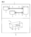
- FIG. 1 1 denotes an illustrated process picture having a plurality of picture objects 2 to 11, which represents a production system to be controlled and is shown together with another picture object in the form of an operating object 12 on a display unit 13 of an operating and monitoring device.
- the operating and monitoring device is part of a process control system, which includes other components such as at least one engineering system, different automation devices, actuators and sensors and other required for controlling the production plant automation components, the parts are connected to each other via a bus.
- the multiple image objects 2 to 11 comprehensive process image 1 and the visualized operating object 12 creates a user as part of a design phase using the engineering system.
- the image objects 2 and 3 each represent a container filled with a first and a second source material and the image object 4 a reactor which mixes and heats the first and second starting materials supplied to it for the production of a final product.
- the other picture objects 5, 6, 7 represent pipelines which connect the containers to the reactor, in the form of image objects 8, 9, 10, 11 indicated valves are provided for opening and closing the pipes.
- the reactor - represented by the image object 4 - must be supplied. It is also believed that, depending on the level of the reactor, it must be heated differently to achieve a particular property of the final product.
- the coordinator X of the operating object 12 assigns the flow rate of the first starting material, the coordinate Y the flow rate of the second starting material, and the coordinate Z the temperature of the reactor as a parameter.
- a configuration software generates a driver block from the configuration data and stores this in the operating and monitoring device, whereby the dependencies of the parameters are stored in this driver block.
- the driver is designed to detect inputs of an operator or operator during process control, to evaluate and to transmit suitable signals to the corresponding automation components according to the evaluation results. Due to these signals, the valves - represented by the image objects 8 to 11 - are controlled in such a way that they are closed or opened according to the operator input and / or that the reactor - represented by the image object 4 - is supplied with energy for heating.
- the operator shifts a ball 14 of the operating object 12 in the XY plane within the cuboid spanned by the X, Y, Z coordinates by means of a mouse, this causes a simultaneous change in the values of the flow rates of the first and second starting material.
- the ball 14 is also displaced in the Z direction, it will be next to it the flow rates of the starting materials simultaneously changed the temperature value, whereby a suitable power supply for the reactor is initiated.
- these are displayed as x, y, z coordinate values 15 in addition to the sphere 14.
- FIG. 2 referenced, in which the in FIG. 1 shown operating object 12 is additionally shown with a locus 16.
- the operator can only change the parameter values with respect to the flow rates of the first and second raw materials and the reactor temperature along this prescribed curve, which represents a restriction to permissible coordinate combinations that correspond to the permissible operating parameters of the system.
- a further image object 17 is designed as a multidimensional slider (FIG. FIG. 3 ).
- a movement of the slide controller along a first axis 18 of a two-axis coordinate system precisely one value of a process parameter can be adjusted or changed.
- the width of a control knob 19 of the slider 17 can be changed along a second axis 20 and also rotated by means of a rotary movement 21 of the control knob 19.
- two further process parameters can be changed or set simultaneously.
Landscapes
- Engineering & Computer Science (AREA)
- Human Computer Interaction (AREA)
- Manufacturing & Machinery (AREA)
- Physics & Mathematics (AREA)
- General Physics & Mathematics (AREA)
- Automation & Control Theory (AREA)
- Feedback Control In General (AREA)
- Testing And Monitoring For Control Systems (AREA)
Description
- Die Erfindung betrifft ein Verfahren zum Visualisieren und Bedienen eines zu steuernden technischen Prozesses mittels eines Bedien- und Beobachtungsgerätes gemäß dem Oberbegriff des Anspruchs 1. Darüber hinaus betrifft die Erfindung ein Bedien- und Beobachtungsgerät, welches zur Durchführung des Verfahrens geeignet ist.
- Ein Verfahren zum Visualisieren und Bedienen eines zu steuernden technischen Prozesses mittels eines Bedien- und Beobachtungsgerätes ist aus dem Siemens-Katalog "ST 80 / ST PC", Ausgabe 2010, Kapitel 2 und 4 bekannt. Das Bedien- und Beobachtungsgerät ist über geeignete Busverbindungen mit Automatisierungskomponenten, z. B. Komponenten in Form von speicherprogrammierbaren Steuerungen, dezentralen Peripheriegeräten und/oder Sensoren und/oder Aktoren, verbunden, wobei diese Automatisierungskomponenten zusammen mit geeigneter Software zur Steuerung eines technischen Prozesses vorgesehen sind. Dabei werden unter dem Begriff "technischer Prozess" sowohl verfahrenstechnische Prozesse als auch Fertigungsabläufe sowie Maschinen und/oder Anlagen verstanden. Das Bedien- und Beobachtungsgerät ist zum Bedienen und Beobachten eines derartigen Prozesses vorgesehen. Beispielsweise kann der Wert eines Prozessparameters in Form einer Temperatur geändert werden, indem ein Anwender bzw. Operator ein auf einer Anzeigeeinheit des Bedien- und Beobachtungsgerätes dargestelltes grafisches Bedienobjekt in Form eines Temperaturschiebers mit einem Bedienelement in Form einer Maus anwählt und diesen Schieber von einer aktuellen Position, welche eine aktuelle Soll-Temperatur repräsentiert, in eine andere Position verschiebt, die eine neue gewünschte Soll-Temperatur darstellt bzw. verkörpert. Aufgrund dieser neu eingestellten Temperatur ändern die Automatisierungskomponenten z. B. die Energiezufuhr eines Heizkessels so lange, bis sich die neue gewünschte Soll-Temperatur im Heizkessel einstellt.
- In komplexen technischen Anlagen, insbesondere in Anlagen der chemischen Industrie, sind gewöhnlich viele Parametereinstellungen erforderlich, wobei häufig die Parameter voneinander abhängig sind. Beispielsweise sind die Eigenschaft und die Konsistenz einer zu erzeugenden chemischen Substanz sowohl von der Reihenfolge der Beimischung der unterschiedlichen Rohstoffe, der Zeitdauer eines Rührvorgangs, der Geschwindigkeit des Rührwerks, der Temperatur und nicht zuletzt von dem Druck im Reaktionsgefäß abhängig. Für jede Parametereinstellung ist daher ein geeignetes visualisiertes Bedienobjekt erforderlich, wobei sich gewöhnlich die Änderung eines Parameterwertes auf einen anderen bereits eingestellten Parameterwert auswirkt, wodurch dieser nochmals eingestellt werden muss, um die gewünschte Eigenschaft und Konsistenz der chemischen Substanz zu erzielen.
- Ein Verfahren gemäß dem Oberbegriff des Anspruchs 1 sowie ein Bedien- und Beobachtungsgerät gemäß dem Oberbegriff des Anspruchs 2 ist aus der
EP 0 511 941 A1 bekannt. - Der Erfindung liegt die Aufgabe zugrunde, ein Verfahren der eingangs genannten Art anzugeben, welches Parametereinstellungen erleichtert. Darüber hinaus ist ein Bedien- und Beobachtungsgerät zu schaffen, welches zur Durchführung des Verfahrens geeignet ist.
- Diese Aufgabe wird im Hinblick auf das Verfahren durch die im kennzeichnenden Teil des Anspruchs 1, bezüglich des Bedien- und Beobachtungsgerätes durch die im kennzeichnenden Teil des Anspruchs 2 angegebenen Maßnahmen gelöst.
- Vorteilhaft ist, dass lediglich ein visualisiertes Bedienobjekt für mehrere Parametereinstellungen erforderlich ist, wobei vorgesehen ist, mittels des Bedienobjekts die Einstellung der abhängigen Prozessparameter auf zulässige Wertekombinationen zu beschränken; auf eine Vielzahl von Bedienobjekten, welche getrennt voneinander für jeweils eine Parametereinstellung vorgesehen sind, kann verzichtet werden.
- Dadurch werden insbesondere Fehleinstellungen vermieden, die zu Prozessstörungen führen könnten. Eine derartige Restriktion ist in dem Bedien- und Beobachtungsgerät hinterlegt und beispielsweise in Form einer Tabelle mit zulässigen Wertekombinationen der abhängigen Prozessparameter, einer Formel oder einer sonstigen geeigneten Regel zur Formulierung bzw. Beschreibung der Parameterabhängigkeiten verwirklicht.
- Die Erfindung geht von der Idee aus, anstatt einer "eindimensionalen" eine "mehrdimensionale" Bedienung vorzusehen, was bedeutet, dass zu einem Zeitpunkt nicht nur der Wert eines Parameters sondern die Werte einer Schar von Parametern gleichzeitig eingestellt bzw. geändert werden können. Als grafisches Bedienobjekt ist z. B. ein mit Koordinaten versehener Quader mit einer darin angeordneten Kugel vorgesehen, welche mit einem Bedienelement in Form einer Maus und einer Tastatur in diesem Quader verschoben bzw. bewegt werden kann. Auf eine Maus und eine Tastatur kann selbstverständlich verzichtet werden, falls die Anzeigeeinheit des Bedien- und Beobachtungsgerätes als so genannter Touch-Screen ausgebildet ist. Jede der drei Raumkoordinaten repräsentiert einen Prozessparameter, z. B. einen Parameter in Form einer Temperatur, eines Drucks oder einer Durchflussmenge, wobei die Position der Kugel die Werte dieser Prozessparameter anzeigt. Die Kugel wird z. B. mittels einer Kombination einer Maus- und einer Tastaturbedienung bewegt, indem die Kugel zunächst angewählt und schließlich gleichzeitig die Maus bewegt wird, das Maus-Scrollrad gedreht und bestimmte Tasten der Tastatur gedrückt werden.
- Für den Fall, dass mehr als drei Prozessparameter gleichzeitig eingestellt werden sollen, können weitere Modifikationen an dem grafischen Bedienobjekt berücksichtigt werden. Beispielsweise können der horizontalen und vertikalen Drehung der Kugel, der Farbe und/oder der Transparenz und/oder dem Schattenwinkel der Kugel sowie der Verformung der Kugel zu einer abflachenden Ellipse hin oder der Geschwindigkeit der Kugelbewegung jeweils ein Parameter zugeordnet werden, wodurch sieben weitere Parameter abgebildet werden können. Die "Kugel-Modifikationen" werden z. B. dadurch bewirkt, indem ein Anwender oder ein Operator die Kugel zunächst anwählt und dann zur selben Zeit das Mausrad dreht und Tasten, z. B. die Tasten "Shift", "Ctrl", "Alt", ..., betätigt.
- Anhand der Zeichnung, in der ein Ausführungsbeispiel der Erfindung veranschaulicht ist, werden im Folgenden die Erfindung, deren Ausgestaltungen sowie Vorteile näher erläutert.
- Es zeigen:
- Figur 1
- auf einem Bedien- und Beobachtungsgerät dargestellte Bildobjekte und
- Figur 2 und 3
- mehrdimensionale Bedienobjekte eines Bedien- und Beobachtungsgerätes.
- In
Figur 1 ist mit 1 ein dargestelltes, mehrere Bildobjekte 2 bis 11 aufweisendes Prozessbild bezeichnet, welches eine zu steuernde Produktionsanlage repräsentiert und zusammen mit einem weiteren Bildobjekt in Form eines Bedienobjekts 12 auf einer Anzeigeeinheit 13 eines Bedien- und Beobachtungsgerätes dargestellt ist. Das Bedien- und Beobachtungsgerät ist Bestandteil eines Prozessleitsystems, welches weitere Bestandteile wie mindestens ein Engineering-System, unterschiedliche Automatisierungsgeräte, ferner Aktoren und Sensoren sowie weitere zur Steuerung der Produktionsanlage erforderliche Automatisierungskomponenten umfasst, wobei die Teile über einen Bus miteinander verbunden sind. - Das mehrere Bildobjekte 2 bis 11 umfassende Prozessbild 1 sowie das visualisierte Bedienobjekt 12 erstellt ein Anwender im Rahmen einer Projektierungsphase mittels des Engineering-Systems. Im vorliegenden Beispiel repräsentieren die Bildobjekte 2 und 3 jeweils einen Behälter, die mit einem ersten und einem zweiten Ausgangsstoff befüllt sind, und das Bild objekt 4 einen Reaktor, welcher zur Herstellung eines Endproduktes die ihm zugeführten ersten und zweiten Ausgangsstoffe mischt und erhitzt. Die weiteren Bildobjekte 5, 6, 7 repräsentieren Rohrleitungen, welche die Behälter mit dem Reaktor verbinden, wobei in Form von Bildobjekten 8, 9, 10, 11 angezeigte Ventile zum Öffnen bzw. Schließen der Rohrleitungen vorgesehen sind.
- Es wird im Folgenden angenommen, dass der erste und zweite Ausgangsstoff in einem Mischungsverhältnis von 2:1 dem Reaktor - repräsentiert durch das Bildobjekt 4 - zugeführt werden muss. Ferner wird angenommen, dass je nach Füllstand des Reaktors dieser unterschiedlich erhitzt werden muss, um eine bestimmte Eigenschaft des Endprodukts zu erzielen.
- In diesem Fall weist ein Projektierer im Rahmen einer Projektierungsphase beispielsweise der Koordinate X des Bedienobjekts 12 die Durchflussmenge des ersten Ausgangsstoffes, der Koordinate Y die Durchflussmenge des zweiten Ausgangsstoffes und der Koordinate Z die Temperatur des Reaktors als Parameter zu. Eine Projektierungs-Software erzeugt aus den Projektierungsdaten einen Treiberbaustein und hinterlegt diesen in dem Bedien- und Beobachtungsgerät, wobei in diesem Treiberbaustein die Abhängigkeiten der Parameter abgespeichert sind. Darüber hinaus ist der Treiber dazu ausgebildet, Eingaben eines Bedieners bzw. Operators während der Prozesssteuerung zu erfassen, auszuwerten und gemäß den Auswerteergebnissen den entsprechenden Automatisierungskomponenten geeignete Signale zu übermitteln. Aufgrund dieser Signale werden die Ventile - repräsentiert durch die Bildobjekte 8 bis 11 - derart angesteuert, dass gemäß der Bedieneingabe diese geschlossen oder geöffnet werden und/oder dass dem Reaktor - repräsentiert durch das Bildobjekt 4 - Energie zum Aufheizen zugeführt wird.
- Für den Fall, dass im vorliegenden Beispiel der Bediener mittels einer Maus eine Kugel 14 des Bedienobjekts 12 in der X-Y-Ebene innerhalb des von den X-, Y-, Z-Koordinaten aufgespannten Quaders verschiebt, bewirkt dies eine gleichzeitige Änderung der Werte der Durchflussmengen des ersten und zweiten Ausgangsstoffes. Das bedeutet, dass die Ventile entsprechend angesteuert werden, um die entsprechende Menge der Ausgangsstoffe zum Reaktor fließen zu lassen. Wird dagegen die Kugel 14 auch in Z-Richtung verschoben, wird neben den Durchflussmengen der Ausgangsstoffe gleichzeitig der Temperaturwert geändert, wodurch eine geeignete Energiezufuhr für den Reaktor eingeleitet wird. Um dem Bediener einen besseren Überblick über die aktuell eingestellten Parameterwerte zu ermöglichen, werden diese als x-, y-, z-Koordinatenwerte 15 zusätzlich zur Kugel 14 angezeigt.
- Um zu gewährleisten, dass der Bediener mittels eines visualisierten Bedienobjekts und eines Bedienelementes nur zulässige Parameterwerte-Kombinationen einstellen kann, ist vorgesehen, den Freiheitsgrad der Bewegung bzw. Verschiebung der Kugel zu beschränken. In diesem Zusammenhang wird auf
Figur 2 verwiesen, in welcher das inFigur 1 gezeigte Bedienobjekt 12 zusätzlich mit einer Ortskurve 16 dargestellt ist. Der Bediener kann die Parameterwerte im Hinblick auf die Durchflussmengen des ersten und zweiten Ausgangsstoffes und der Reaktortemperatur nur entlang dieses vorgeschriebenen Kurvenverlaufs ändern, was eine Beschränkung auf zulässige Koordinatenkombinationen darstellt, welche den zulässigen Betriebsparametern der Anlage entsprechen. - Im Unterschied zu dem in Form eines Quaders mit einer Kugel 14 ausgebildeten Bedienobjekt 12 ist ein weiteres Bildobjekt 17 als multidimensionaler Schieberegler ausgebildet (
Figur 3 ). Mittels einer Bewegung des Schiebereglers entlang einer ersten Achse 18 eines zweiachsigen Koordinatensystems lässt sich genau ein Wert eines Prozessparameters verstellen bzw. verändern. Ferner kann die Breite eines Bedienknopfes 19 des Schiebereglers 17 entlang einer zweiten Achse 20 verändert und darüber hinaus mittels einer Drehbewegung 21 des Bedienknopfes 19 verdreht werden. Dadurch können zwei weitere Prozessparameter gleichzeitig verändert bzw. eingestellt werden. - Weitere Parametereinstellungen mittels des Schiebereglers 17 werden dadurch ermöglicht, dass der Farbe der Vorderseite und der Farbe der Oberseite des Schiebereglers 17 sowie der Neigung des Bedienknopfes zur Seite jeweils ein Parameter zugewiesen wird. Hierdurch ergibt sich eine Dimension von sechs Parametern, die mit einer einzigen Bedienung in zueinander konformer Weise gleichzeitig verstellt bzw. geändert werden.
Claims (2)
- Verfahren zum Visualisieren und Bedienen eines zu steuernden technischen Prozesses mittels eines Bedien- und Beobachtungsgerätes, welcher durch ein visualisiertes Prozessbild (1) repräsentiert wird, wobei mittels eines visualisierten Bedienobjekts (12, 17) und eines Bedienelementes zwei voneinander abhängige Prozessparameter eingestellt werden, dadurch gekennzeichnet, dass mittels des visualisierten Bedienobjektes (12, 17) und des Bedienelementes gleichzeitig die zwei und ein von den zwei Prozessparametern abhängiger weiterer Prozessparameter eingestellt werden, und dass mittels des Bedienobjekts (12, 17) die Einstellung der abhängigen Prozessparameter auf zulässige Wertekombinationen beschränkt wird, wobei Parameterwerte nur entlang einer Ortskurve (16) des visualisierten Bedienobjektes (12, 17) eingestellt werden können.
- Bedien- und Beobachtungsgerät zum Visualisieren und Bedienen eines zu steuernden technischen Prozesses, wobei mindestens ein visualisiertes Prozessbild (1) den Prozess repräsentiert und ein visualisiertes Bedienobjekt (12, 17) und ein Bedienelement zum Einstellen von zwei voneinander abhängigen Prozessparametern vorgesehen sind, dadurch gekennzeichnet, dass das visualisierte Bedienobjekt (12, 17) und das Bedienelement ausgebildet sind, gleichzeitig die zwei Prozessparameter und einen von den zwei Prozessparametern abhängigen weiteren Prozessparameter einzustellen, und die Einstellung der abhängigen Prozessparameter auf zulässige Wertekombinationen zu beschränken, wobei Parameterwerte nur entlang einer Ortskurve (16) des visualisierten Bedienobjektes (12, 17) eingestellt werden können.
Priority Applications (1)
| Application Number | Priority Date | Filing Date | Title |
|---|---|---|---|
| EP20100193208 EP2458464B1 (de) | 2010-11-30 | 2010-11-30 | Verfahren zum Visualisieren und Bedienen eines zu steuernden technischen Prozesses |
Applications Claiming Priority (1)
| Application Number | Priority Date | Filing Date | Title |
|---|---|---|---|
| EP20100193208 EP2458464B1 (de) | 2010-11-30 | 2010-11-30 | Verfahren zum Visualisieren und Bedienen eines zu steuernden technischen Prozesses |
Publications (2)
| Publication Number | Publication Date |
|---|---|
| EP2458464A1 EP2458464A1 (de) | 2012-05-30 |
| EP2458464B1 true EP2458464B1 (de) | 2014-10-29 |
Family
ID=43923673
Family Applications (1)
| Application Number | Title | Priority Date | Filing Date |
|---|---|---|---|
| EP20100193208 Not-in-force EP2458464B1 (de) | 2010-11-30 | 2010-11-30 | Verfahren zum Visualisieren und Bedienen eines zu steuernden technischen Prozesses |
Country Status (1)
| Country | Link |
|---|---|
| EP (1) | EP2458464B1 (de) |
Families Citing this family (1)
| Publication number | Priority date | Publication date | Assignee | Title |
|---|---|---|---|---|
| EP3805882B1 (de) * | 2019-10-10 | 2022-06-08 | Siemens Aktiengesellschaft | Leitsystem für eine technische anlage mit trendkurvendiagramm |
Family Cites Families (3)
| Publication number | Priority date | Publication date | Assignee | Title |
|---|---|---|---|---|
| EP0511941A1 (de) * | 1991-04-30 | 1992-11-04 | Maschinenfabrik Rieter Ag | Vorrichtung zur Steuerung einer Spinnereianlage oder eine Spinnereimaschine |
| JP3082169B2 (ja) * | 1991-11-20 | 2000-08-28 | インターナショナル・ビジネス・マシーンズ・コーポレ−ション | データ処理システム及びその実行方法 |
| US7720552B1 (en) * | 2006-06-05 | 2010-05-18 | Rockwell Automation Technologies, Inc. | Virtual knob lever arm as analog control element |
-
2010
- 2010-11-30 EP EP20100193208 patent/EP2458464B1/de not_active Not-in-force
Also Published As
| Publication number | Publication date |
|---|---|
| EP2458464A1 (de) | 2012-05-30 |
Similar Documents
| Publication | Publication Date | Title |
|---|---|---|
| EP1184757B1 (de) | Flow chart Programmierung für industrielle Steuerungen, insbesondere Bewegungssteuerungen | |
| EP2367083B1 (de) | Vorrichtung zur Erstellung eines Programms für eine speicherprogrammierbare Steuerung, Programmiereinrichtung und Verfahren zur Programmierung einer speicherprogrammierbaren Steuerung | |
| EP2016470B1 (de) | Bediengerät zum informationsaustausch mit einem feldgerät in einem automatisierungssystem | |
| DE102007004341A1 (de) | Fortschrittliches Tool zur Verwaltung eines Prozesssteuerungsnetzwerks | |
| DE102018124414A1 (de) | Systeme und verfahren zur einfachen entwicklung der grafischen anzeigekonfiguration in einer prozesskontrollanlage | |
| DE19938490B4 (de) | Verfahren zur Überprüfung einer Anlage | |
| DE102013100465A1 (de) | Mikroprozessor-gesteuerte Steuerungseinrichtung für eine Spritzgiessanlage | |
| EP2453326A1 (de) | Verfahren und System zur Bedienung einer Maschine aus der Automatisierungstechnik | |
| EP3067768B1 (de) | Automatisierungseinrichtung und Operator-System | |
| DE102008013400B4 (de) | Verfahren zur Ermittlung von Verriegelungsbereichen wenigstens eines im Raum bewegbaren ersten Objekts | |
| AT522653B1 (de) | Verfahren zur Darstellung und Bedienung von Produktionsmitteln, insbesondere für die kunststoffverarbeitende Industrie | |
| DE102016103700A1 (de) | Steuerkonsole | |
| EP3805882B1 (de) | Leitsystem für eine technische anlage mit trendkurvendiagramm | |
| DE102007062453A1 (de) | Verfahren zum Programmieren und/oder Diagnostizieren einer speicherprogrammierbaren Steuerung | |
| EP0564538B1 (de) | Verfahren zur computergestützten steuerung einer maschine bzw. eines prozesses | |
| EP2458464A1 (de) | Verfahren zum Visualisieren und Bedienen eines zu steuernden technischen Prozesses | |
| EP2455827A1 (de) | Feldgerät mit einem Energiesparmodus, der über jede der zwei Schnittstellen des Feldgerätes aktiviert und deaktiviert werden kann | |
| DE102018119321A1 (de) | Kontrollierter Rollout von Modulklassen | |
| DE102014007386A1 (de) | Verfahren und Einrichtung zur Verwaltung und Konfiguration von Feldgeräten einer Automatisierungsanlage | |
| EP1640826B2 (de) | Darstellung von Prozesswerten in der Automatisierungstechnik | |
| DE102017214695B4 (de) | Elektronische Einrichtung und numerische Steuereinrichtung | |
| DE102011084809A1 (de) | Benutzerschnittstelle und Verfahren zur rechnergestützten Ansteuerung einer Benutzerschnittstelle | |
| EP2012227A1 (de) | Programmieroberfläche zum Programmieren von Computern | |
| EP2328050A1 (de) | Verfahren zum Betreiben eines Engineering-Systems und Engineering-System | |
| EP4509935B1 (de) | Verfahren zum konfigurieren eines sps-geräts und ein sps-verwaltungssystem zum ausführen des verfahrens |
Legal Events
| Date | Code | Title | Description |
|---|---|---|---|
| PUAI | Public reference made under article 153(3) epc to a published international application that has entered the european phase |
Free format text: ORIGINAL CODE: 0009012 |
|
| AK | Designated contracting states |
Kind code of ref document: A1 Designated state(s): AL AT BE BG CH CY CZ DE DK EE ES FI FR GB GR HR HU IE IS IT LI LT LU LV MC MK MT NL NO PL PT RO RS SE SI SK SM TR |
|
| AX | Request for extension of the european patent |
Extension state: BA ME |
|
| 17P | Request for examination filed |
Effective date: 20121105 |
|
| RAP1 | Party data changed (applicant data changed or rights of an application transferred) |
Owner name: SIEMENS AKTIENGESELLSCHAFT |
|
| RIC1 | Information provided on ipc code assigned before grant |
Ipc: G05B 19/409 20060101AFI20140128BHEP |
|
| GRAJ | Information related to disapproval of communication of intention to grant by the applicant or resumption of examination proceedings by the epo deleted |
Free format text: ORIGINAL CODE: EPIDOSDIGR1 |
|
| GRAP | Despatch of communication of intention to grant a patent |
Free format text: ORIGINAL CODE: EPIDOSNIGR1 |
|
| GRAP | Despatch of communication of intention to grant a patent |
Free format text: ORIGINAL CODE: EPIDOSNIGR1 |
|
| INTG | Intention to grant announced |
Effective date: 20140402 |
|
| INTC | Intention to grant announced (deleted) | ||
| INTG | Intention to grant announced |
Effective date: 20140417 |
|
| GRAJ | Information related to disapproval of communication of intention to grant by the applicant or resumption of examination proceedings by the epo deleted |
Free format text: ORIGINAL CODE: EPIDOSDIGR1 |
|
| GRAP | Despatch of communication of intention to grant a patent |
Free format text: ORIGINAL CODE: EPIDOSNIGR1 |
|
| INTG | Intention to grant announced |
Effective date: 20140602 |
|
| GRAS | Grant fee paid |
Free format text: ORIGINAL CODE: EPIDOSNIGR3 |
|
| GRAA | (expected) grant |
Free format text: ORIGINAL CODE: 0009210 |
|
| AK | Designated contracting states |
Kind code of ref document: B1 Designated state(s): AL AT BE BG CH CY CZ DE DK EE ES FI FR GB GR HR HU IE IS IT LI LT LU LV MC MK MT NL NO PL PT RO RS SE SI SK SM TR |
|
| REG | Reference to a national code |
Ref country code: GB Ref legal event code: FG4D Free format text: NOT ENGLISH |
|
| REG | Reference to a national code |
Ref country code: CH Ref legal event code: EP |
|
| REG | Reference to a national code |
Ref country code: AT Ref legal event code: REF Ref document number: 693874 Country of ref document: AT Kind code of ref document: T Effective date: 20141115 |
|
| REG | Reference to a national code |
Ref country code: IE Ref legal event code: FG4D Free format text: LANGUAGE OF EP DOCUMENT: GERMAN |
|
| REG | Reference to a national code |
Ref country code: DE Ref legal event code: R096 Ref document number: 502010008135 Country of ref document: DE Effective date: 20141211 |
|
| REG | Reference to a national code |
Ref country code: NL Ref legal event code: VDEP Effective date: 20141029 |
|
| REG | Reference to a national code |
Ref country code: LT Ref legal event code: MG4D |
|
| PG25 | Lapsed in a contracting state [announced via postgrant information from national office to epo] |
Ref country code: PT Free format text: LAPSE BECAUSE OF FAILURE TO SUBMIT A TRANSLATION OF THE DESCRIPTION OR TO PAY THE FEE WITHIN THE PRESCRIBED TIME-LIMIT Effective date: 20150302 Ref country code: NL Free format text: LAPSE BECAUSE OF FAILURE TO SUBMIT A TRANSLATION OF THE DESCRIPTION OR TO PAY THE FEE WITHIN THE PRESCRIBED TIME-LIMIT Effective date: 20141029 Ref country code: ES Free format text: LAPSE BECAUSE OF FAILURE TO SUBMIT A TRANSLATION OF THE DESCRIPTION OR TO PAY THE FEE WITHIN THE PRESCRIBED TIME-LIMIT Effective date: 20141029 Ref country code: FI Free format text: LAPSE BECAUSE OF FAILURE TO SUBMIT A TRANSLATION OF THE DESCRIPTION OR TO PAY THE FEE WITHIN THE PRESCRIBED TIME-LIMIT Effective date: 20141029 Ref country code: IS Free format text: LAPSE BECAUSE OF FAILURE TO SUBMIT A TRANSLATION OF THE DESCRIPTION OR TO PAY THE FEE WITHIN THE PRESCRIBED TIME-LIMIT Effective date: 20150228 Ref country code: LT Free format text: LAPSE BECAUSE OF FAILURE TO SUBMIT A TRANSLATION OF THE DESCRIPTION OR TO PAY THE FEE WITHIN THE PRESCRIBED TIME-LIMIT Effective date: 20141029 Ref country code: NO Free format text: LAPSE BECAUSE OF FAILURE TO SUBMIT A TRANSLATION OF THE DESCRIPTION OR TO PAY THE FEE WITHIN THE PRESCRIBED TIME-LIMIT Effective date: 20150129 |
|
| PG25 | Lapsed in a contracting state [announced via postgrant information from national office to epo] |
Ref country code: LV Free format text: LAPSE BECAUSE OF FAILURE TO SUBMIT A TRANSLATION OF THE DESCRIPTION OR TO PAY THE FEE WITHIN THE PRESCRIBED TIME-LIMIT Effective date: 20141029 Ref country code: PL Free format text: LAPSE BECAUSE OF FAILURE TO SUBMIT A TRANSLATION OF THE DESCRIPTION OR TO PAY THE FEE WITHIN THE PRESCRIBED TIME-LIMIT Effective date: 20141029 Ref country code: SE Free format text: LAPSE BECAUSE OF FAILURE TO SUBMIT A TRANSLATION OF THE DESCRIPTION OR TO PAY THE FEE WITHIN THE PRESCRIBED TIME-LIMIT Effective date: 20141029 Ref country code: HR Free format text: LAPSE BECAUSE OF FAILURE TO SUBMIT A TRANSLATION OF THE DESCRIPTION OR TO PAY THE FEE WITHIN THE PRESCRIBED TIME-LIMIT Effective date: 20141029 Ref country code: GR Free format text: LAPSE BECAUSE OF FAILURE TO SUBMIT A TRANSLATION OF THE DESCRIPTION OR TO PAY THE FEE WITHIN THE PRESCRIBED TIME-LIMIT Effective date: 20150130 Ref country code: CY Free format text: LAPSE BECAUSE OF FAILURE TO SUBMIT A TRANSLATION OF THE DESCRIPTION OR TO PAY THE FEE WITHIN THE PRESCRIBED TIME-LIMIT Effective date: 20141029 Ref country code: RS Free format text: LAPSE BECAUSE OF FAILURE TO SUBMIT A TRANSLATION OF THE DESCRIPTION OR TO PAY THE FEE WITHIN THE PRESCRIBED TIME-LIMIT Effective date: 20141029 |
|
| PG25 | Lapsed in a contracting state [announced via postgrant information from national office to epo] |
Ref country code: BE Free format text: LAPSE BECAUSE OF NON-PAYMENT OF DUE FEES Effective date: 20141130 |
|
| REG | Reference to a national code |
Ref country code: CH Ref legal event code: PL |
|
| REG | Reference to a national code |
Ref country code: DE Ref legal event code: R097 Ref document number: 502010008135 Country of ref document: DE |
|
| PG25 | Lapsed in a contracting state [announced via postgrant information from national office to epo] |
Ref country code: LI Free format text: LAPSE BECAUSE OF NON-PAYMENT OF DUE FEES Effective date: 20141130 Ref country code: MC Free format text: LAPSE BECAUSE OF FAILURE TO SUBMIT A TRANSLATION OF THE DESCRIPTION OR TO PAY THE FEE WITHIN THE PRESCRIBED TIME-LIMIT Effective date: 20141029 Ref country code: DK Free format text: LAPSE BECAUSE OF FAILURE TO SUBMIT A TRANSLATION OF THE DESCRIPTION OR TO PAY THE FEE WITHIN THE PRESCRIBED TIME-LIMIT Effective date: 20141029 Ref country code: SK Free format text: LAPSE BECAUSE OF FAILURE TO SUBMIT A TRANSLATION OF THE DESCRIPTION OR TO PAY THE FEE WITHIN THE PRESCRIBED TIME-LIMIT Effective date: 20141029 Ref country code: EE Free format text: LAPSE BECAUSE OF FAILURE TO SUBMIT A TRANSLATION OF THE DESCRIPTION OR TO PAY THE FEE WITHIN THE PRESCRIBED TIME-LIMIT Effective date: 20141029 Ref country code: RO Free format text: LAPSE BECAUSE OF FAILURE TO SUBMIT A TRANSLATION OF THE DESCRIPTION OR TO PAY THE FEE WITHIN THE PRESCRIBED TIME-LIMIT Effective date: 20141029 Ref country code: CH Free format text: LAPSE BECAUSE OF NON-PAYMENT OF DUE FEES Effective date: 20141130 Ref country code: CZ Free format text: LAPSE BECAUSE OF FAILURE TO SUBMIT A TRANSLATION OF THE DESCRIPTION OR TO PAY THE FEE WITHIN THE PRESCRIBED TIME-LIMIT Effective date: 20141029 |
|
| REG | Reference to a national code |
Ref country code: IE Ref legal event code: MM4A |
|
| PLBE | No opposition filed within time limit |
Free format text: ORIGINAL CODE: 0009261 |
|
| STAA | Information on the status of an ep patent application or granted ep patent |
Free format text: STATUS: NO OPPOSITION FILED WITHIN TIME LIMIT |
|
| 26N | No opposition filed |
Effective date: 20150730 |
|
| PG25 | Lapsed in a contracting state [announced via postgrant information from national office to epo] |
Ref country code: IE Free format text: LAPSE BECAUSE OF NON-PAYMENT OF DUE FEES Effective date: 20141130 |
|
| REG | Reference to a national code |
Ref country code: FR Ref legal event code: PLFP Year of fee payment: 6 |
|
| PG25 | Lapsed in a contracting state [announced via postgrant information from national office to epo] |
Ref country code: SI Free format text: LAPSE BECAUSE OF FAILURE TO SUBMIT A TRANSLATION OF THE DESCRIPTION OR TO PAY THE FEE WITHIN THE PRESCRIBED TIME-LIMIT Effective date: 20141029 |
|
| PG25 | Lapsed in a contracting state [announced via postgrant information from national office to epo] |
Ref country code: SM Free format text: LAPSE BECAUSE OF FAILURE TO SUBMIT A TRANSLATION OF THE DESCRIPTION OR TO PAY THE FEE WITHIN THE PRESCRIBED TIME-LIMIT Effective date: 20141029 |
|
| PG25 | Lapsed in a contracting state [announced via postgrant information from national office to epo] |
Ref country code: BG Free format text: LAPSE BECAUSE OF FAILURE TO SUBMIT A TRANSLATION OF THE DESCRIPTION OR TO PAY THE FEE WITHIN THE PRESCRIBED TIME-LIMIT Effective date: 20141029 |
|
| PG25 | Lapsed in a contracting state [announced via postgrant information from national office to epo] |
Ref country code: HU Free format text: LAPSE BECAUSE OF FAILURE TO SUBMIT A TRANSLATION OF THE DESCRIPTION OR TO PAY THE FEE WITHIN THE PRESCRIBED TIME-LIMIT; INVALID AB INITIO Effective date: 20101130 Ref country code: TR Free format text: LAPSE BECAUSE OF FAILURE TO SUBMIT A TRANSLATION OF THE DESCRIPTION OR TO PAY THE FEE WITHIN THE PRESCRIBED TIME-LIMIT Effective date: 20141029 Ref country code: LU Free format text: LAPSE BECAUSE OF NON-PAYMENT OF DUE FEES Effective date: 20141130 Ref country code: MT Free format text: LAPSE BECAUSE OF FAILURE TO SUBMIT A TRANSLATION OF THE DESCRIPTION OR TO PAY THE FEE WITHIN THE PRESCRIBED TIME-LIMIT Effective date: 20141029 |
|
| REG | Reference to a national code |
Ref country code: FR Ref legal event code: PLFP Year of fee payment: 7 |
|
| REG | Reference to a national code |
Ref country code: AT Ref legal event code: MM01 Ref document number: 693874 Country of ref document: AT Kind code of ref document: T Effective date: 20151130 |
|
| PG25 | Lapsed in a contracting state [announced via postgrant information from national office to epo] |
Ref country code: AT Free format text: LAPSE BECAUSE OF NON-PAYMENT OF DUE FEES Effective date: 20151130 |
|
| REG | Reference to a national code |
Ref country code: FR Ref legal event code: PLFP Year of fee payment: 8 |
|
| PG25 | Lapsed in a contracting state [announced via postgrant information from national office to epo] |
Ref country code: MK Free format text: LAPSE BECAUSE OF FAILURE TO SUBMIT A TRANSLATION OF THE DESCRIPTION OR TO PAY THE FEE WITHIN THE PRESCRIBED TIME-LIMIT Effective date: 20141029 |
|
| PG25 | Lapsed in a contracting state [announced via postgrant information from national office to epo] |
Ref country code: AL Free format text: LAPSE BECAUSE OF FAILURE TO SUBMIT A TRANSLATION OF THE DESCRIPTION OR TO PAY THE FEE WITHIN THE PRESCRIBED TIME-LIMIT Effective date: 20141029 |
|
| PGFP | Annual fee paid to national office [announced via postgrant information from national office to epo] |
Ref country code: FR Payment date: 20201112 Year of fee payment: 11 Ref country code: GB Payment date: 20201202 Year of fee payment: 11 Ref country code: IT Payment date: 20201123 Year of fee payment: 11 |
|
| PGFP | Annual fee paid to national office [announced via postgrant information from national office to epo] |
Ref country code: DE Payment date: 20210119 Year of fee payment: 11 |
|
| REG | Reference to a national code |
Ref country code: DE Ref legal event code: R119 Ref document number: 502010008135 Country of ref document: DE |
|
| GBPC | Gb: european patent ceased through non-payment of renewal fee |
Effective date: 20211130 |
|
| PG25 | Lapsed in a contracting state [announced via postgrant information from national office to epo] |
Ref country code: GB Free format text: LAPSE BECAUSE OF NON-PAYMENT OF DUE FEES Effective date: 20211130 Ref country code: DE Free format text: LAPSE BECAUSE OF NON-PAYMENT OF DUE FEES Effective date: 20220601 |
|
| PG25 | Lapsed in a contracting state [announced via postgrant information from national office to epo] |
Ref country code: FR Free format text: LAPSE BECAUSE OF NON-PAYMENT OF DUE FEES Effective date: 20211130 |
|
| PG25 | Lapsed in a contracting state [announced via postgrant information from national office to epo] |
Ref country code: IT Free format text: LAPSE BECAUSE OF NON-PAYMENT OF DUE FEES Effective date: 20211130 |