EP2458314A2 - Wärmetauscher mit innerer Flüssigkeit zur Betätigung der externen Flüssigkeitspumpe - Google Patents
Wärmetauscher mit innerer Flüssigkeit zur Betätigung der externen Flüssigkeitspumpe Download PDFInfo
- Publication number
- EP2458314A2 EP2458314A2 EP11190385A EP11190385A EP2458314A2 EP 2458314 A2 EP2458314 A2 EP 2458314A2 EP 11190385 A EP11190385 A EP 11190385A EP 11190385 A EP11190385 A EP 11190385A EP 2458314 A2 EP2458314 A2 EP 2458314A2
- Authority
- EP
- European Patent Office
- Prior art keywords
- fluid
- heat exchanger
- thermal
- energy
- actuation device
- Prior art date
- Legal status (The legal status is an assumption and is not a legal conclusion. Google has not performed a legal analysis and makes no representation as to the accuracy of the status listed.)
- Withdrawn
Links
Images


Classifications
-
- F—MECHANICAL ENGINEERING; LIGHTING; HEATING; WEAPONS; BLASTING
- F02—COMBUSTION ENGINES; HOT-GAS OR COMBUSTION-PRODUCT ENGINE PLANTS
- F02C—GAS-TURBINE PLANTS; AIR INTAKES FOR JET-PROPULSION PLANTS; CONTROLLING FUEL SUPPLY IN AIR-BREATHING JET-PROPULSION PLANTS
- F02C1/00—Gas-turbine plants characterised by the use of hot gases or unheated pressurised gases, as the working fluid
-
- F—MECHANICAL ENGINEERING; LIGHTING; HEATING; WEAPONS; BLASTING
- F28—HEAT EXCHANGE IN GENERAL
- F28D—HEAT-EXCHANGE APPARATUS, NOT PROVIDED FOR IN ANOTHER SUBCLASS, IN WHICH THE HEAT-EXCHANGE MEDIA DO NOT COME INTO DIRECT CONTACT
- F28D15/00—Heat-exchange apparatus with the intermediate heat-transfer medium in closed tubes passing into or through the conduit walls ; Heat-exchange apparatus employing intermediate heat-transfer medium or bodies
- F28D15/02—Heat-exchange apparatus with the intermediate heat-transfer medium in closed tubes passing into or through the conduit walls ; Heat-exchange apparatus employing intermediate heat-transfer medium or bodies in which the medium condenses and evaporates, e.g. heat pipes
- F28D15/0266—Heat-exchange apparatus with the intermediate heat-transfer medium in closed tubes passing into or through the conduit walls ; Heat-exchange apparatus employing intermediate heat-transfer medium or bodies in which the medium condenses and evaporates, e.g. heat pipes with separate evaporating and condensing chambers connected by at least one conduit; Loop-type heat pipes; with multiple or common evaporating or condensing chambers
-
- H—ELECTRICITY
- H01—ELECTRIC ELEMENTS
- H01L—SEMICONDUCTOR DEVICES NOT COVERED BY CLASS H10
- H01L23/00—Details of semiconductor or other solid state devices
- H01L23/34—Arrangements for cooling, heating, ventilating or temperature compensation ; Temperature sensing arrangements
- H01L23/42—Fillings or auxiliary members in containers or encapsulations selected or arranged to facilitate heating or cooling
- H01L23/427—Cooling by change of state, e.g. use of heat pipes
-
- F—MECHANICAL ENGINEERING; LIGHTING; HEATING; WEAPONS; BLASTING
- F28—HEAT EXCHANGE IN GENERAL
- F28D—HEAT-EXCHANGE APPARATUS, NOT PROVIDED FOR IN ANOTHER SUBCLASS, IN WHICH THE HEAT-EXCHANGE MEDIA DO NOT COME INTO DIRECT CONTACT
- F28D15/00—Heat-exchange apparatus with the intermediate heat-transfer medium in closed tubes passing into or through the conduit walls ; Heat-exchange apparatus employing intermediate heat-transfer medium or bodies
- F28D15/02—Heat-exchange apparatus with the intermediate heat-transfer medium in closed tubes passing into or through the conduit walls ; Heat-exchange apparatus employing intermediate heat-transfer medium or bodies in which the medium condenses and evaporates, e.g. heat pipes
- F28D2015/0291—Heat-exchange apparatus with the intermediate heat-transfer medium in closed tubes passing into or through the conduit walls ; Heat-exchange apparatus employing intermediate heat-transfer medium or bodies in which the medium condenses and evaporates, e.g. heat pipes comprising internal rotor means, e.g. turbine driven by the working fluid
-
- F—MECHANICAL ENGINEERING; LIGHTING; HEATING; WEAPONS; BLASTING
- F28—HEAT EXCHANGE IN GENERAL
- F28F—DETAILS OF HEAT-EXCHANGE AND HEAT-TRANSFER APPARATUS, OF GENERAL APPLICATION
- F28F2250/00—Arrangements for modifying the flow of the heat exchange media, e.g. flow guiding means; Particular flow patterns
- F28F2250/08—Fluid driving means, e.g. pumps, fans
-
- H—ELECTRICITY
- H01—ELECTRIC ELEMENTS
- H01L—SEMICONDUCTOR DEVICES NOT COVERED BY CLASS H10
- H01L23/00—Details of semiconductor or other solid state devices
- H01L23/34—Arrangements for cooling, heating, ventilating or temperature compensation ; Temperature sensing arrangements
- H01L23/46—Arrangements for cooling, heating, ventilating or temperature compensation ; Temperature sensing arrangements involving the transfer of heat by flowing fluids
- H01L23/467—Arrangements for cooling, heating, ventilating or temperature compensation ; Temperature sensing arrangements involving the transfer of heat by flowing fluids by flowing gases, e.g. air
-
- H—ELECTRICITY
- H01—ELECTRIC ELEMENTS
- H01L—SEMICONDUCTOR DEVICES NOT COVERED BY CLASS H10
- H01L2924/00—Indexing scheme for arrangements or methods for connecting or disconnecting semiconductor or solid-state bodies as covered by H01L24/00
- H01L2924/0001—Technical content checked by a classifier
- H01L2924/0002—Not covered by any one of groups H01L24/00, H01L24/00 and H01L2224/00
-
- Y—GENERAL TAGGING OF NEW TECHNOLOGICAL DEVELOPMENTS; GENERAL TAGGING OF CROSS-SECTIONAL TECHNOLOGIES SPANNING OVER SEVERAL SECTIONS OF THE IPC; TECHNICAL SUBJECTS COVERED BY FORMER USPC CROSS-REFERENCE ART COLLECTIONS [XRACs] AND DIGESTS
- Y02—TECHNOLOGIES OR APPLICATIONS FOR MITIGATION OR ADAPTATION AGAINST CLIMATE CHANGE
- Y02E—REDUCTION OF GREENHOUSE GAS [GHG] EMISSIONS, RELATED TO ENERGY GENERATION, TRANSMISSION OR DISTRIBUTION
- Y02E10/00—Energy generation through renewable energy sources
- Y02E10/20—Hydro energy
Definitions
- the present invention provides a heat exchanger with inner fluid to actuate the external fluid pump capable of driving one or more than one of fluid actuation devices through fluids passing through the heat exchanger having thermal-energy fluid pipe, without utilizing external mechanical rotational kinetic energy or power of electric motors; respectively driving external fluid pumping blade devices installed at lateral sides of the heat exchanger having thermal-energy fluid pipe with a direct or non-contact transmission means, so as to drive the external fluid to pass through the heat exchanger for increasing the heat exchange efficiency of the heat exchanger.
- a conventional heat exchanger having thermal-energy fluid pipe often rotates external fluid pumping blade devices through external mechanical rotational kinetic energy or power of electric motor, so as to drive the external fluid to pass through the heat exchanger having thermal-energy fluid pipe for increasing the heat exchange efficiency of the heat exchanger.
- disadvantages of the conventional art are raising the installation cost and consuming unnecessary energy.
- the heat exchanger with inner fluid to actuate the external fluid pump drives one or more than one of fluid actuation devices for generating rotational kinetic energy through thermal-energy fluid passing through a heat exchanger composed by fluid pipe; and external fluid pumping blade devices installed at lateral sides of the heat exchanger having thermal-energy fluid pipe are respectively driven with a direct or non-contact transmission means, so as to drive the external fluid to pass through the heat exchanger having thermal-energy fluid pipe for increasing the heat exchange efficiency of the heat exchanger having thermal-energy fluid pipe.
- a heat exchanger comprises a heat exchanger device (100) arranged to permit passage of a fluid from an input to an output through the heat exchanger device (100); at least one output/input pipeline (102, 103) of a fluid actuation device assembly (20) connected in parallel and disposed between the input and the output of the heat exchanger device (100), or are connected in series with the input and/or the output of the heat exchanger (100), then two ends of the fluid actuation device assembly (20) and the heat exchanger device (100) being connected in series are used for outputting/inputting fluid; and a fluid actuation device assembly (20) comprised of the output/input pipeline (102, 103), and the flow of fluid in the output/input pipeline (102, 103) of the fluid actuation device assembly (20) arranged to drive the fluid powering blade device (221), then the output shaft of the fluid powering blade device (221) arranged to drive the external fluid pumping blade device (202) directly, or the fluid powering blade device (2
- a conventional heat exchanger having thermal-energy fluid pipe often rotates external fluid pumping blade devices through external mechanical rotational kinetic energy or power of electric motor, so as to drive the external fluid to pass through the heat exchanger having thermal-energy fluid pipe for increasing the heat exchange efficiency of the heat exchanger having thermal-energy fluid pipe.
- disadvantages of the conventional art are raising the installation cost and consuming unnecessary energy;
- the present invention provides a heat exchanger with inner fluid to actuate the external fluid pump capable of driving one or more than one of fluid actuation devices through fluids passing through heat exchanger having thermal-energy fluid pipe, without utilizing external mechanical rotational kinetic energy or power of electric motors; respectively driving external fluid pumping blade devices installed at lateral sides of the heat exchanger having thermal-energy fluid pipe with a direct or non-contact transmission means, so as to drive the external fluid to pass through the heat exchanger having thermal-energy fluid pipe for increasing the heat exchange efficiency of the heat exchanger having thermal-energy fluid pipe;
- Embodiments of the heat exchanger with inner fluid to actuate the external fluid pump according to the present invention are as followings:
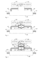
- FIG 2 is a schematic structural view showing the embodiment of present invention that a direct-driving type fluid actuation device (200) drives an external fluid pumping blade device (202) in the heat exchanger having thermal-energy fluid pipe; As shown in FIG 2 , it mainly consists of:
- FIG 3 is a schematic structural view showing the embodiment of the present invention that a non-contact transmission type fluid actuation device (2000) drives an external fluid pumping blade device (202) in the heat exchanger having thermal-energy fluid pipe; As shown in FIG 3 , it mainly consists of:
- the fluid powering blade device (221) installed inside the active side of non-contact transmission type fluid actuation device (220) and the passive rotating part of magnetic coupling member (211) installed inside the output side of non-contact transmission type fluid actuation device (210) can perform synchronous or non-synchronous rotational transmission coupling through the active rotating part of magnetic coupling member (212) combined with the fluid powering blade device (221), for driving the passive rotating part of magnetic coupling member (211) and the rotating shaft (201), thereby further driving the external fluid pumping blade device (202) installed at the side of the heat exchanger having thermal-energy fluid pipe (100);
- the relative locations of the direct-driving type fluid actuation device (200) or the non-contact transmission type fluid actuation device (2000) and the heat exchanger having thermal-energy fluid pipe (100) are structured as followings:
- FIG 5 is a schematic structural view showing the embodiment of the present invention that the external fluid pumping blade device (202) is installed between the non-contact transmission type fluid actuation device (2000) and the heat exchanger having thermal-energy fluid pipe (100); As shown in FIG 5 , it mainly consists of:
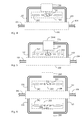
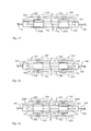
- FIG 6 is a schematic structural view showing that the direct-driving type fluid actuation devices (200) is installed at any two of the top, the bottom, the right, the left, the front and the rear sides of the heat exchanger having thermal-energy fluid pipe (100), and the two external fluid pumping blade devices (202) thereof being respectively installed between the heat exchanger having thermal-energy fluid pipe (100) and the direct-driving type fluid actuation devices (200) installed at two sides of the heat exchanger having thermal-energy fluid pipe (100); As shown in FIG 6 , it mainly consists of:
- FIG 7 is a schematic structural view showing that the non-contact transmission type fluid actuation devices (2000) is installed at any two of the top, the bottom, the right, the left, the front and the rear sides of the heat exchanger having thermal-energy fluid pipe (100), and the two external fluid pumping blade devices (202) thereof are respectively installed between the heat exchanger having thermal-energy fluid pipe (100) and the non-contact transmission type fluid actuation devices (2000) installed at two sides of the heat exchanger having thermal-energy fluid pipe (100); As shown in FIG 7 , it mainly consists of:
- FIG 8 is a schematic structural view showing that the direct-driving type fluid actuation devices (200) is installed at any two of the top, the bottom, the right, the left, the front and the rear sides of the heat exchanger having thermal-energy fluid pipe (100), and the two external fluid pumping blade devices (202) thereof are respectively installed at the outer sides of the direct-driving type fluid actuation devices (200) installed at two sides of the heat exchanger having thermal-energy fluid pipe (100); As shown in FIG 8 , it mainly consists of:
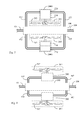
- FIG 9 is a schematic structural view showing that the non-contact transmission type fluid actuation devices (2000) is installed at any two of the top, the bottom, the right, the left, the front and the rear sides of the heat exchanger having thermal-energy fluid pipe (100), and the two external fluid pumping blade devices (202) thereof are respectively installed at the outer sides of the non-contact transmission type fluid actuation devices (2000) installed at two sides of the heat exchanger having thermal-energy fluid pipe (100); As shown in FIG 9 , it mainly consists of:
- FIG 10 is a schematic structural view showing that the direct-driving type fluid actuation devices (200) are installed at any two of the top, the bottom, the right, the left, the front and the rear sides of the heat exchanger having thermal-energy fluid pipe (100), and one of the two external fluid pumping blade devices (202) thereof is installed between the heat exchanger having thermal-energy fluid pipe (100) and the combined direct-driving type fluid actuation device (200) and the other thereof is installed at the outer side of the other direct-driving type fluid actuation device (200) combined with the heat exchanger having thermal-energy fluid pipe (100); As shown in FIG 10 , it mainly consists of:
- FIG 11 is a schematic structural view showing that the non-contact transmission type fluid actuation devices (2000) is installed at any two of the top, the bottom, the right, the left, the front and the rear sides of the heat exchanger having thermal-energy fluid pipe (100), and one of the two external fluid pumping blade devices (202) thereof is installed between the heat exchanger having thermal-energy fluid pipe (100) and the combined non-contact transmission type fluid actuation device (2000) and the other thereof is installed at the outer side of the other non-contact transmission type fluid actuation device (2000) combined with the heat exchanger having thermal-energy fluid pipe (100); As shown in FIG 11 , it mainly consists of:
- the direct-driving type fluid actuation device (200) or the non-contact transmission type fluid actuation device (2000) can be further installed inside the heat exchanger having thermal-energy fluid pipe (100), and using the rotating shaft (201) to drive the external fluid pumping blade devices (202) for reducing the thickness of the whole structure;
- the present invention when in practical application, can be structured as followings which include:
- FIG 13 is a schematic structural view showing the embodiment of the present invention that the non-contact transmission type fluid actuation device (2000) is installed inside the heat exchanger having thermal-energy fluid pipe (100), and the external fluid pumping blade device (202) being driven by a rotating shaft (201) installed at one side thereof; As shown in FIG 13 , it mainly consists of:
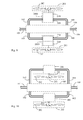
- FIG 14 is a schematic structural view showing the embodiment of the present invention that the direct-driving type fluid actuation device (200) is installed inside the heat exchanger having thermal-energy fluid pipe (100), and the connected external fluid pumping blade devices (202) are respectively driven by two ends of the rotating shaft (201); As shown in FIG 14 , it mainly consists of:
- FIG 15 is a schematic structural view showing the embodiment of present invention that a dual-output non-contact transmission type fluid actuation device (3000) is installed inside the heat exchanger having thermal-energy fluid pipe (100), and the connected external fluid pumping blade devices (202) are respectively driven by individual rotating shafts (201) of the output sides of non-contact transmission type fluid actuation device (210) installed at two sides of the dual-output non-contact transmission type fluid actuation device (3000); As shown in FIG 15 , it mainly consists of:
- FIG 17 is a schematic structural view showing the embodiment of present invention that two or more than two of the non-contact transmission type fluid actuation devices (2000) are installed inside the heat exchanger having thermal-energy fluid pipe (100), and rotating shafts (201) of the non-contact transmission type fluid actuation devices (2000) installed at the same side respectively drive the external fluid pumping blade devices (202); As shown in FIG 17 , it mainly consists of:
- FIG 18 is a schematic structural view showing the embodiment of present invention that two or more than two of the direct-driving type fluid actuation devices (200) are installed inside the heat exchanger having thermal-energy fluid pipe (100), and two ends of each rotating shafts (201) of the direct-driving type fluid actuation devices (200) respectively drive the connected external fluid pumping blade devices (202);
- FIG 18 it mainly consists of:
- FIG 19 is a schematic structural view showing the embodiment of present invention that two or more than two of the dual-output non-contact transmission type fluid actuation devices (3000) are installed inside the heat exchanger having thermal-energy fluid pipe (100), and individual rotating shafts (201) of the output sides of non-contact transmission type fluid actuation device (210) installed at two sides of the dual-output non-contact transmission type fluid actuation devices (3000) respectively drive the connected external fluid pumping blade devices (202); As shown in FIG 19 , it mainly consists of:
- the present invention when in practical application, can further be structured as followings which include:
Landscapes
- Engineering & Computer Science (AREA)
- Physics & Mathematics (AREA)
- Mechanical Engineering (AREA)
- General Engineering & Computer Science (AREA)
- Thermal Sciences (AREA)
- Microelectronics & Electronic Packaging (AREA)
- General Physics & Mathematics (AREA)
- Computer Hardware Design (AREA)
- Condensed Matter Physics & Semiconductors (AREA)
- Power Engineering (AREA)
- Life Sciences & Earth Sciences (AREA)
- Sustainable Development (AREA)
- Chemical & Material Sciences (AREA)
- Combustion & Propulsion (AREA)
- Structures Of Non-Positive Displacement Pumps (AREA)
- Heat-Exchange Devices With Radiators And Conduit Assemblies (AREA)
- Fluid-Pressure Circuits (AREA)
- Electromagnetic Pumps, Or The Like (AREA)
Applications Claiming Priority (1)
| Application Number | Priority Date | Filing Date | Title |
|---|---|---|---|
| US12/953,521 US20120125575A1 (en) | 2010-11-24 | 2010-11-24 | Cold/heat discharge with inner fluid to actuate the external fluid pump |
Publications (2)
| Publication Number | Publication Date |
|---|---|
| EP2458314A2 true EP2458314A2 (de) | 2012-05-30 |
| EP2458314A3 EP2458314A3 (de) | 2015-04-15 |
Family
ID=45217265
Family Applications (1)
| Application Number | Title | Priority Date | Filing Date |
|---|---|---|---|
| EP11190385.2A Withdrawn EP2458314A3 (de) | 2010-11-24 | 2011-11-23 | Wärmetauscher mit innerer Flüssigkeit zur Betätigung der externen Flüssigkeitspumpe |
Country Status (9)
| Country | Link |
|---|---|
| US (2) | US20120125575A1 (de) |
| EP (1) | EP2458314A3 (de) |
| JP (1) | JP2012112643A (de) |
| CN (2) | CN102477971A (de) |
| AU (1) | AU2011253640A1 (de) |
| CA (1) | CA2758707A1 (de) |
| MX (1) | MX2011012497A (de) |
| SG (1) | SG181254A1 (de) |
| TW (2) | TWM440429U (de) |
Cited By (2)
| Publication number | Priority date | Publication date | Assignee | Title |
|---|---|---|---|---|
| WO2015135761A1 (de) * | 2014-03-11 | 2015-09-17 | Siemens Aktiengesellschaft | Modul mit fluidenergiemaschine |
| CN110132562A (zh) * | 2019-05-16 | 2019-08-16 | 清华大学 | 一种叶轮进风量检测装置 |
Families Citing this family (6)
| Publication number | Priority date | Publication date | Assignee | Title |
|---|---|---|---|---|
| US20120125575A1 (en) * | 2010-11-24 | 2012-05-24 | Tai-Her Yang | Cold/heat discharge with inner fluid to actuate the external fluid pump |
| KR102392820B1 (ko) * | 2015-05-21 | 2022-05-02 | 주식회사 브라이트론 | 회전팬 블레이드부 자체의 표면냉각효과를 이용한 냉각팬 |
| CN105263301B (zh) * | 2015-11-12 | 2017-12-19 | 深圳市研派科技有限公司 | 一种液冷散热系统及其液体散热排 |
| CN108884806B (zh) * | 2016-03-22 | 2020-12-29 | Ntn株式会社 | 水轮机、用在水轮机中的由两个阳螺纹轴组成的连接结构、以及两个轴的连接结构 |
| US10925222B2 (en) | 2017-11-02 | 2021-02-23 | Larry C. Sarver | Wireless self-powered flow sensor system and ethernet decoder |
| CN110441056B (zh) * | 2019-09-09 | 2021-02-05 | 合肥工业大学 | 一种非接触式机械能传递试验台及其试验方法 |
Family Cites Families (21)
| Publication number | Priority date | Publication date | Assignee | Title |
|---|---|---|---|---|
| US2038347A (en) * | 1936-04-21 | Air conditioned heating and cooling | ||
| US1208790A (en) * | 1904-11-08 | 1916-12-19 | Hugo Junkers | Heating and cooling apparatus. |
| US946889A (en) * | 1907-11-20 | 1910-01-18 | Jules C Veil | Heating, cooling, and ventilating system. |
| US1826950A (en) * | 1928-01-18 | 1931-10-13 | John Wood Mfg Co | Heat exchange apparatus |
| US1885751A (en) * | 1928-12-24 | 1932-11-01 | Modine Mfg Co | Heating device |
| US2065720A (en) * | 1935-09-16 | 1936-12-29 | Morneautt Louis | Automatic heater for motor vehicles |
| US2186145A (en) * | 1936-07-06 | 1940-01-09 | Deane E Perham | Air conditioning apparatus |
| US2220754A (en) * | 1938-09-03 | 1940-11-05 | Jr Edward S Cornell | Steam heating system with steam powered air circulation means |
| US2568807A (en) * | 1948-04-02 | 1951-09-25 | John R Jaye | Heat exchange apparatus |
| US2649082A (en) * | 1950-06-03 | 1953-08-18 | Engineering Controls Inc | Engine cooling system utilizing waste heat |
| GB1423350A (en) * | 1972-05-12 | 1976-02-04 | Cooling Dev Ltd | Gas-moving devices |
| JPH0419988Y2 (de) * | 1986-03-07 | 1992-05-07 | ||
| JP4178437B2 (ja) * | 2000-02-02 | 2008-11-12 | 三菱電機株式会社 | 冷凍空調装置 |
| DE10237133A1 (de) * | 2002-08-13 | 2004-02-26 | BSH Bosch und Siemens Hausgeräte GmbH | Wärmetauscher-Turbine-Anordnung |
| US7509999B2 (en) * | 2002-09-28 | 2009-03-31 | Ebm-Papst St. Georgen Gmbh & Co. Kg | Arrangement and method for removing heat from a component which is to be cooled |
| JP2007057114A (ja) * | 2005-08-22 | 2007-03-08 | Sanyo Electric Co Ltd | 空気調和装置 |
| JP2007064532A (ja) * | 2005-08-30 | 2007-03-15 | Cosel Co Ltd | 放熱システム |
| FR2913755A1 (fr) * | 2007-03-14 | 2008-09-19 | Jose Breard | Dispositif de ventilation pour echangeur thermique |
| JP2008232576A (ja) * | 2007-03-22 | 2008-10-02 | Sanden Corp | 給湯装置 |
| JP2009085481A (ja) * | 2007-09-28 | 2009-04-23 | Daikin Ind Ltd | 冷凍装置 |
| US20120125575A1 (en) * | 2010-11-24 | 2012-05-24 | Tai-Her Yang | Cold/heat discharge with inner fluid to actuate the external fluid pump |
-
2010
- 2010-11-24 US US12/953,521 patent/US20120125575A1/en not_active Abandoned
-
2011
- 2011-11-17 SG SG2011085222A patent/SG181254A1/en unknown
- 2011-11-18 JP JP2011252656A patent/JP2012112643A/ja active Pending
- 2011-11-18 CA CA2758707A patent/CA2758707A1/en not_active Abandoned
- 2011-11-22 CN CN201110373214XA patent/CN102477971A/zh active Pending
- 2011-11-22 CN CN2011204663852U patent/CN202402242U/zh not_active Expired - Fee Related
- 2011-11-23 EP EP11190385.2A patent/EP2458314A3/de not_active Withdrawn
- 2011-11-23 AU AU2011253640A patent/AU2011253640A1/en not_active Abandoned
- 2011-11-24 MX MX2011012497A patent/MX2011012497A/es unknown
- 2011-11-24 TW TW100222177U patent/TWM440429U/zh not_active IP Right Cessation
- 2011-11-24 TW TW100143028A patent/TW201231818A/zh unknown
-
2014
- 2014-10-16 US US14/516,065 patent/US20150047810A1/en not_active Abandoned
Non-Patent Citations (1)
| Title |
|---|
| None |
Cited By (2)
| Publication number | Priority date | Publication date | Assignee | Title |
|---|---|---|---|---|
| WO2015135761A1 (de) * | 2014-03-11 | 2015-09-17 | Siemens Aktiengesellschaft | Modul mit fluidenergiemaschine |
| CN110132562A (zh) * | 2019-05-16 | 2019-08-16 | 清华大学 | 一种叶轮进风量检测装置 |
Also Published As
| Publication number | Publication date |
|---|---|
| CN202402242U (zh) | 2012-08-29 |
| AU2011253640A1 (en) | 2012-06-07 |
| US20150047810A1 (en) | 2015-02-19 |
| MX2011012497A (es) | 2012-05-23 |
| TWM440429U (en) | 2012-11-01 |
| US20120125575A1 (en) | 2012-05-24 |
| SG181254A1 (en) | 2012-06-28 |
| CN102477971A (zh) | 2012-05-30 |
| CA2758707A1 (en) | 2012-05-24 |
| EP2458314A3 (de) | 2015-04-15 |
| TW201231818A (en) | 2012-08-01 |
| JP2012112643A (ja) | 2012-06-14 |
Similar Documents
| Publication | Publication Date | Title |
|---|---|---|
| EP2458314A2 (de) | Wärmetauscher mit innerer Flüssigkeit zur Betätigung der externen Flüssigkeitspumpe | |
| US10590935B2 (en) | Automotive electric liquid pump | |
| US20150369258A1 (en) | Fluid device | |
| US8742612B1 (en) | Turbine having counter-rotating armature and field | |
| KR102014785B1 (ko) | 전기 모터 구동 펌프 | |
| US20200313482A1 (en) | Brushless electric motor system comprising a rotor, a stator and power electronic means | |
| GB2485184B (en) | Axial flux electrical machines | |
| JP2009235928A (ja) | 液圧ポンプユニット | |
| JP4867543B2 (ja) | ポンプ手段を具えたモータ | |
| Zeaiter | Thermal modeling and cooling of electric motors: Application to the propulsion of hybrid aircraft | |
| EP2559950B1 (de) | Gebäude-Heiz-Kühl-System mit gepumpter Sekundärflüssigkeit | |
| EP3055554B1 (de) | Hydraulische energierückgewinnungsturbine mit integriertem lagerkupplungsgehäuse | |
| KR101355648B1 (ko) | 풍력발전기 | |
| US9599097B2 (en) | Fluid power generating apparatus | |
| JP2017166467A (ja) | 流体機械及び変速装置 | |
| EP1931016A2 (de) | Drehender elektrischer Motor mit Magnetantrieb | |
| US11146157B2 (en) | Dual rotor electric machine in an automotive application | |
| CN100451390C (zh) | 挠性及刚性双态耦合器 |
Legal Events
| Date | Code | Title | Description |
|---|---|---|---|
| PUAI | Public reference made under article 153(3) epc to a published international application that has entered the european phase |
Free format text: ORIGINAL CODE: 0009012 |
|
| AK | Designated contracting states |
Kind code of ref document: A2 Designated state(s): AL AT BE BG CH CY CZ DE DK EE ES FI FR GB GR HR HU IE IS IT LI LT LU LV MC MK MT NL NO PL PT RO RS SE SI SK SM TR |
|
| AX | Request for extension of the european patent |
Extension state: BA ME |
|
| PUAL | Search report despatched |
Free format text: ORIGINAL CODE: 0009013 |
|
| AK | Designated contracting states |
Kind code of ref document: A3 Designated state(s): AL AT BE BG CH CY CZ DE DK EE ES FI FR GB GR HR HU IE IS IT LI LT LU LV MC MK MT NL NO PL PT RO RS SE SI SK SM TR |
|
| AX | Request for extension of the european patent |
Extension state: BA ME |
|
| RIC1 | Information provided on ipc code assigned before grant |
Ipc: F28D 15/02 20060101ALI20150306BHEP Ipc: H05K 7/20 20060101ALI20150306BHEP Ipc: F28D 15/00 20060101AFI20150306BHEP Ipc: H01L 23/46 20060101ALI20150306BHEP |
|
| STAA | Information on the status of an ep patent application or granted ep patent |
Free format text: STATUS: THE APPLICATION IS DEEMED TO BE WITHDRAWN |
|
| 18D | Application deemed to be withdrawn |
Effective date: 20151016 |