EP2458147A2 - Axialdurchströmte Gasturbine - Google Patents
Axialdurchströmte Gasturbine Download PDFInfo
- Publication number
- EP2458147A2 EP2458147A2 EP11190647A EP11190647A EP2458147A2 EP 2458147 A2 EP2458147 A2 EP 2458147A2 EP 11190647 A EP11190647 A EP 11190647A EP 11190647 A EP11190647 A EP 11190647A EP 2458147 A2 EP2458147 A2 EP 2458147A2
- Authority
- EP
- European Patent Office
- Prior art keywords
- blades
- rotor
- air
- gas turbine
- heat shields
- Prior art date
- Legal status (The legal status is an assumption and is not a legal conclusion. Google has not performed a legal analysis and makes no representation as to the accuracy of the status listed.)
- Withdrawn
Links
Images


Classifications
-
- F—MECHANICAL ENGINEERING; LIGHTING; HEATING; WEAPONS; BLASTING
- F01—MACHINES OR ENGINES IN GENERAL; ENGINE PLANTS IN GENERAL; STEAM ENGINES
- F01D—NON-POSITIVE DISPLACEMENT MACHINES OR ENGINES, e.g. STEAM TURBINES
- F01D5/00—Blades; Blade-carrying members; Heating, heat-insulating, cooling or antivibration means on the blades or the members
- F01D5/02—Blade-carrying members, e.g. rotors
- F01D5/08—Heating, heat-insulating or cooling means
- F01D5/081—Cooling fluid being directed on the side of the rotor disc or at the roots of the blades
- F01D5/084—Cooling fluid being directed on the side of the rotor disc or at the roots of the blades the fluid circulating at the periphery of a multistage rotor, e.g. of drum type
-
- F—MECHANICAL ENGINEERING; LIGHTING; HEATING; WEAPONS; BLASTING
- F01—MACHINES OR ENGINES IN GENERAL; ENGINE PLANTS IN GENERAL; STEAM ENGINES
- F01D—NON-POSITIVE DISPLACEMENT MACHINES OR ENGINES, e.g. STEAM TURBINES
- F01D25/00—Component parts, details, or accessories, not provided for in, or of interest apart from, other groups
- F01D25/08—Cooling; Heating; Heat-insulation
- F01D25/12—Cooling
-
- F—MECHANICAL ENGINEERING; LIGHTING; HEATING; WEAPONS; BLASTING
- F01—MACHINES OR ENGINES IN GENERAL; ENGINE PLANTS IN GENERAL; STEAM ENGINES
- F01D—NON-POSITIVE DISPLACEMENT MACHINES OR ENGINES, e.g. STEAM TURBINES
- F01D5/00—Blades; Blade-carrying members; Heating, heat-insulating, cooling or antivibration means on the blades or the members
- F01D5/02—Blade-carrying members, e.g. rotors
- F01D5/08—Heating, heat-insulating or cooling means
- F01D5/081—Cooling fluid being directed on the side of the rotor disc or at the roots of the blades
Definitions
- the present invention relates to the technology of gas turbines. It refers to a gas turbine of the axial flow type according to the preamble of claim 1.
- a gas turbine is composed of a stator and a rotor.
- the stator constitutes a casing with stator heat shields and vanes installed in it.
- the turbine rotor arranged coaxially within the stator casing consists of a rotating shaft with axial slots of fir-tree type used to install blades.
- Several blade rows and rotor heat shields are installed therein, alternating. Hot gas formed in a combustion chamber passes through profiled channels between the vanes, and, when striking against the blades, makes the turbine rotor to rotate.
- the components of the hot gas channel, especially the blades, vanes and heat shields, of the turbine experience a very high thermal load. Furthermore, the blades are at the same time subject to a very high mechanical stress caused by the centrifugal forces at high rotational speeds of the rotor.
- FIG. 1 A different cooling scheme according to the prior art is shown in Fig. 1 .
- the gas turbine 10 of Fig. 1 comprises a plurality of stages the first three of which are shown in the Figure.
- the gas turbine 10 comprises a rotor 13, which rotates around a central machine axis, not shown.
- the rotor 13 has a rotor shaft 15 with axial slots of the fir-tree type used to install a plurality of blades B1, B2 and B3.
- the blades B1, B2 and B3 of Fig. 1 are arranged in three blade rows. Interposed between adjacent blade rows are rotor heat shields R1 and R2.
- the blades B1, B2, B3 and the rotor heat shields are evenly distributed around the circumference of the rotor shaft 15.
- Each of the blades B1, B2 and B3 has an inner platform, which - together with the respective platforms of the other blades of the same row - constitutes a closed ring around the machine axis.
- the inner platforms of blades B1, B2 and B3 in combination with the rotor heat shields R1 and R2 form an inner outline of the turbine flow path or hot gas path 12.
- the hot gas path 12 is bordered by the surrounding stator 11 with its stator heat shields S1, S2 and S3 and vanes V1, V2 and V3.
- the inner outline separates a rotor cooling air transit cavity, which conducts a main flow of cooling air 17, from the hot gas flow within the hot gas path 12.
- sealing plates 19 are installed between adjacent blades B1-B3 and rotor heat shields R1, R2.
- air cools the rotor shaft 15 when flowing in axial direction along the common flow path between blade necks of blades B1-B3 and rotor heat shields R1, R2; this air passes consecutively through the inner cavity of the blade B1, then in turn through blade B2 and blade B3 cavities.
- the gas turbine of the invention is of the axial flow type and comprises a rotor and a stator, which stator constitutes a casing surrounding the rotor, thereby providing a hot gas path, through which hot gas formed in a combustion chamber passes, whereby the rotor comprises a rotor shaft with axial slots, especially of the fir-tree type, for receiving a plurality of blades, which are arranged in a series of blade rows, with rotor heat shields interposed between adjacent blade rows, thereby forming an inner outline of the hot gas path, and whereby the rotor shaft is configured to conduct a main flow of cooling air in axial direction along the rotor heat shields and the lower parts of the blades, and whereby the rotor shaft supplies the blades with cooling air entering the interior of the blades.
- air-tight cooling channels are provided, which extend axially through the rotor shaft separate from the main flow of cooling air, and supply the blades with cooling air.
- the stator comprises a vane carrier, wherein stator heat shields and vanes are installed, with the stator heat shields lying opposite to the blades and the vanes lying opposite to the rotor heat shields.
- each blade row comprises the same definite number of blades in the same angular arrangement, and there is at least one air-tight cooling channel provided for one angular blade position of the blade rows, which air-tight cooling channel extends through the respective blades of all blade rows being arranged at the same angular position.
- the air-tight cooling channels are established by means of coaxial cylindrical openings passing in axial direction through the rotor heat shields and the lower parts of the blades, and by means of sleeves, which connect the openings of adjacent blades and rotor heat shields in an air-tight fashion.
- air-tight cooling channels are closed at their ends by means of a plug.
- the connecting sleeves are configured to allow a relative displacement of the parts being connected without losing air-tightness of the connection.
- the connecting sleeves have at each end a spherical section on their outside, which allows the swivelling of the sleeves within a cylindrical opening similar to a ball joint.
- the connecting sleeves are of reduced mass without sacrificing their stiffness by providing a plurality of circumferentially distributed axial ribs.
- the axial ribs may be provided at the inner side of the connecting sleeves.
- the axial ribs may be provided at the outer side of the connecting sleeves, whereby the radial height of the ribs is smaller than the radial height of the spherical sections.
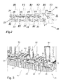
- Fig. 2 and Fig. 3 show a gas turbine with a blade cooling configuration according to an embodiment of the invention.
- the gas turbine 20 of Fig. 2 comprises a plurality of stages the first three of which are shown in the Figure. Similar to Fig. 1 , the gas turbine 20 comprises a rotor 13 with a rotor shaft 15 and the blades B1, B2 and B3.
- the blades B1, B2 and B3 are again arranged in three blade rows. Interposed between adjacent blade rows are rotor heat shields R1 and R2.
- the blades B1, B2, B3 and the rotor heat shields are evenly distributed around the circumference of the rotor shaft 15.
- Each of the blades B1, B2 and B3 has an inner platform, which - together with the respective platforms of the other blades of the same row - constitutes a closed ring around the machine axis.
- the inner platforms of blades B1, B2 and B3 in combination with the rotor heat shields R1 and R2 form an inner outline of the turbine flow path or hot gas path 12.
- Opposite to the rotor heat shields R1 and R2 are rows of vanes V2 and V3.
- a first row of vanes V1 is arranged at the entrance of the hot gas path, which is entered by the hot gas 16.
- the inner outline separates a rotor cooling air transit cavity, which again conducts a main flow of cooling air 17, from the hot gas flow within the hot gas path 12.
- sealing plates 19 are installed between adjacent blades B1-B3 and rotor heat shields R1, R2.
- the basic difference and advantage of the proposed design according to Fig. 2 is availability of air-tight cooling channels 21 separated from the main cooling air flow 17 passing along the shaft 15.
- the number of these cooling channels 21 corresponds to the number of blades B1, B2 and B3 in circumferential direction in each of the blade rows. For this reason, the number of blades and the circumferential distribution of the blades is the same in each turbine stage or blade row (see Figs. 6 and 7 ).
- the cooling channels 21 are used to separately supply the blades B1, B2 and B3 with cooling air. They are formed by providing coaxial cylindrical openings 28 passing through the blade B1, rotor heat shield R1, blade B2, rotor heat shield R2, and blade B3. Each channel 21 is terminated with a plug 24 mounted at the end of the corresponding opening 28 of blade B3. Air-tightness of channels 21 is reached by means of cylindrical sleeves 22, 23 (see Figs. 4, 5 ), which are each installed with one of its ends in a recess of a corresponding blade, and - with its other end - in a recess of the corresponding adjacent rotor heat shield. The sleeves 22, 23 are shaped so that they do not prevent adjacent parts from mutual radial and axial displacements (see Fig. 4 ).
- the openings 28 in blades B1-B3 and rotor heat shields R1, R2 are cylindrical. They are shaped so to provide minimum clearance within the contact zone between said recess and the cylindrical sleeves 22, 23 by means of machining. Thus, both overflow and mixing between main flow 17 and the flow in a channel 21 are prevented by nearly zero clearance within the contact zones between sleeves 22, 23 on the one side, and blades B1-B3 and rotor heat shields R1, R2 on the another side.
- the proposed rotor design with longitudinal cooling air supply to blades B1-B3 through a separate channel 21 according to Fig. 2 has also an advantage as compared with the typical known design ( Fig. 1 ) because, with regard to point 4 above, it can be even used without mounting the sleeves 22, 23.
- Fig. 4 shows embodiments of sleeves, which provide a means for organization of a nearly air-tight channel 21 for cooling air transportation between the rotor parts.
- Tightness of the channel 21 is attained by means of cylindrically shaped sockets made at the ends of openings 28 in adjacent rotor heat shields and blades.
- the cylindrical shape of the sockets has been chosen because such a socket can be manufactured by machining with high accuracy in the simplest manner.
- spherical sections 25 at both ends of the sleeves 22, 23 make it possible to keep the channels 21 air-tight even when the sockets go out of alignment in both circumferential and radial direction.
- the spherical sections 25 at the ends of the sleeves 22, 23 can also be machined with high accuracy.
- ribs may be provided at those sleeves.
- those ribs 26 may be provided on the inner surface of the sleeves 22'.
- such ribs 27 can be also arranged on the outer surface of the sleeves 23'. In this case the spherical sections 25 should have a greater radial height than the ribs 27.
Landscapes
- Engineering & Computer Science (AREA)
- Mechanical Engineering (AREA)
- General Engineering & Computer Science (AREA)
- Turbine Rotor Nozzle Sealing (AREA)
Applications Claiming Priority (1)
| Application Number | Priority Date | Filing Date | Title |
|---|---|---|---|
| RU2010148730/06A RU2539404C2 (ru) | 2010-11-29 | 2010-11-29 | Осевая газовая турбина |
Publications (2)
| Publication Number | Publication Date |
|---|---|
| EP2458147A2 true EP2458147A2 (de) | 2012-05-30 |
| EP2458147A3 EP2458147A3 (de) | 2014-08-06 |
Family
ID=45033868
Family Applications (1)
| Application Number | Title | Priority Date | Filing Date |
|---|---|---|---|
| EP11190647.5A Withdrawn EP2458147A3 (de) | 2010-11-29 | 2011-11-24 | Axialdurchströmte Gasturbine |
Country Status (7)
| Country | Link |
|---|---|
| US (1) | US8932007B2 (de) |
| EP (1) | EP2458147A3 (de) |
| JP (1) | JP5841415B2 (de) |
| CN (1) | CN102562174B (de) |
| AU (1) | AU2011250787B2 (de) |
| MY (1) | MY157543A (de) |
| RU (1) | RU2539404C2 (de) |
Cited By (3)
| Publication number | Priority date | Publication date | Assignee | Title |
|---|---|---|---|---|
| CN103470318A (zh) * | 2012-06-06 | 2013-12-25 | 通用电气公司 | 控制涡轮发动机压缩机温度的方法及涡轮发动机的压缩机 |
| EP3106613A1 (de) * | 2015-06-06 | 2016-12-21 | United Technologies Corporation | Kühlsystem für gasturbinentriebwerken |
| US10001061B2 (en) | 2014-06-06 | 2018-06-19 | United Technologies Corporation | Cooling system for gas turbine engines |
Families Citing this family (11)
| Publication number | Priority date | Publication date | Assignee | Title |
|---|---|---|---|---|
| US20130034445A1 (en) * | 2011-08-03 | 2013-02-07 | General Electric Company | Turbine bucket having axially extending groove |
| US9938831B2 (en) * | 2011-10-28 | 2018-04-10 | United Technologies Corporation | Spoked rotor for a gas turbine engine |
| US10006364B2 (en) * | 2014-08-20 | 2018-06-26 | United Technologies Corporation | Gas turbine rotors |
| EP3093432B1 (de) * | 2015-05-15 | 2021-04-21 | Ansaldo Energia Switzerland AG | Verfahren zur kühlung einer gasturbine sowie gasturbine zur durchführung des verfahrens |
| CN106640208A (zh) * | 2015-10-31 | 2017-05-10 | 熵零股份有限公司 | 一种叶轮机构 |
| US10641174B2 (en) | 2017-01-18 | 2020-05-05 | General Electric Company | Rotor shaft cooling |
| US11060530B2 (en) | 2018-01-04 | 2021-07-13 | General Electric Company | Compressor cooling in a gas turbine engine |
| US11525400B2 (en) | 2020-07-08 | 2022-12-13 | General Electric Company | System for rotor assembly thermal gradient reduction |
| US11692485B2 (en) | 2021-02-18 | 2023-07-04 | Generai, Electric Company | Gas turbine engine with spoolie fluid transfer connection |
| US11674396B2 (en) | 2021-07-30 | 2023-06-13 | General Electric Company | Cooling air delivery assembly |
| US12044172B2 (en) | 2022-11-02 | 2024-07-23 | General Electric Company | Air guide for a gas turbine engine |
Citations (3)
| Publication number | Priority date | Publication date | Assignee | Title |
|---|---|---|---|---|
| EP0909878A2 (de) | 1997-10-17 | 1999-04-21 | Hitachi, Ltd. | Gasturbine |
| EP1098067A2 (de) | 1999-11-05 | 2001-05-09 | Hitachi, Ltd. | Kühlstruktur für Gasturbinenlaufschaufeln |
| US6860110B2 (en) | 2001-02-14 | 2005-03-01 | Hitachi, Ltd. | Gas turbine shaft and heat shield cooling arrangement |
Family Cites Families (30)
| Publication number | Priority date | Publication date | Assignee | Title |
|---|---|---|---|---|
| GB612097A (en) * | 1946-10-09 | 1948-11-08 | English Electric Co Ltd | Improvements in and relating to the cooling of gas turbine rotors |
| US2684831A (en) * | 1947-11-28 | 1954-07-27 | Power Jets Res & Dev Ltd | Turbine and like rotor |
| GB789197A (en) * | 1956-01-06 | 1958-01-15 | British Thomson Houston Co Ltd | Improvements in cooling systems for high temperature turbines |
| US2977090A (en) * | 1956-06-12 | 1961-03-28 | Daniel J Mccarty | Heat responsive means for blade cooling |
| US3748060A (en) * | 1971-09-14 | 1973-07-24 | Westinghouse Electric Corp | Sideplate for turbine blade |
| US5593274A (en) * | 1995-03-31 | 1997-01-14 | General Electric Co. | Closed or open circuit cooling of turbine rotor components |
| KR100389990B1 (ko) * | 1995-04-06 | 2003-11-17 | 가부시끼가이샤 히다치 세이사꾸쇼 | 가스터빈 |
| US5558496A (en) * | 1995-08-21 | 1996-09-24 | General Electric Company | Removing particles from gas turbine coolant |
| JP3448145B2 (ja) * | 1995-11-24 | 2003-09-16 | 三菱重工業株式会社 | 熱回収式ガスタービンロータ |
| US5755556A (en) * | 1996-05-17 | 1998-05-26 | Westinghouse Electric Corporation | Turbomachine rotor with improved cooling |
| PL330755A1 (en) * | 1996-06-21 | 1999-05-24 | Siemens Ag | Turbine shaft as well as method of cooling same |
| US6393829B2 (en) * | 1996-11-29 | 2002-05-28 | Hitachi, Ltd. | Coolant recovery type gas turbine |
| JP3634871B2 (ja) * | 1996-11-29 | 2005-03-30 | 株式会社日立製作所 | ガスタービン |
| JP3442959B2 (ja) * | 1997-02-21 | 2003-09-02 | 三菱重工業株式会社 | ガスタービン動翼の冷却媒体通路 |
| US5984636A (en) * | 1997-12-17 | 1999-11-16 | Pratt & Whitney Canada Inc. | Cooling arrangement for turbine rotor |
| SE512085C2 (sv) * | 1998-05-28 | 2000-01-24 | Abb Ab | Rotormaskininrättning |
| US6422818B2 (en) * | 1998-08-07 | 2002-07-23 | General Electric Company | Lubricating system for thermal medium delivery parts in a gas turbine |
| KR100697471B1 (ko) * | 1999-05-14 | 2007-03-20 | 제너럴 일렉트릭 캄파니 | 가스 터빈 로터의 유지 슬리브 |
| ATE318994T1 (de) * | 1999-08-24 | 2006-03-15 | Gen Electric | Dampfkühlungssystem für eine gasturbine |
| EP1079068A3 (de) * | 1999-08-27 | 2004-01-07 | General Electric Company | Verbindungsmuffe für den Kühlkreislauf eines Turbinenrotors |
| JP2001123802A (ja) | 1999-10-28 | 2001-05-08 | Hitachi Ltd | タービンロータ |
| JP3361501B2 (ja) * | 2000-03-02 | 2003-01-07 | 株式会社日立製作所 | 閉回路翼冷却タービン |
| JP2002309906A (ja) * | 2001-04-11 | 2002-10-23 | Mitsubishi Heavy Ind Ltd | 蒸気冷却型ガスタービン |
| JP3762661B2 (ja) * | 2001-05-31 | 2006-04-05 | 株式会社日立製作所 | タービンロータ |
| US6506021B1 (en) * | 2001-10-31 | 2003-01-14 | General Electric Company | Cooling system for a gas turbine |
| JP2003206701A (ja) * | 2002-01-11 | 2003-07-25 | Mitsubishi Heavy Ind Ltd | ガスタービンのタービンローターおよびガスタービン |
| DE502007005296D1 (de) * | 2006-12-19 | 2010-11-18 | Alstom Technology Ltd | Strömungsmaschine, insbesondere gasturbine |
| US8047786B2 (en) * | 2008-01-10 | 2011-11-01 | General Electric Company | Apparatus for plugging turbine wheel holes |
| JP5322664B2 (ja) | 2009-01-14 | 2013-10-23 | 株式会社東芝 | 蒸気タービン及びその冷却方法 |
| US8113784B2 (en) * | 2009-03-20 | 2012-02-14 | Hamilton Sundstrand Corporation | Coolable airfoil attachment section |
-
2010
- 2010-11-29 RU RU2010148730/06A patent/RU2539404C2/ru not_active IP Right Cessation
-
2011
- 2011-11-15 AU AU2011250787A patent/AU2011250787B2/en not_active Ceased
- 2011-11-22 MY MYPI2011005639A patent/MY157543A/en unknown
- 2011-11-24 EP EP11190647.5A patent/EP2458147A3/de not_active Withdrawn
- 2011-11-29 US US13/306,006 patent/US8932007B2/en not_active Expired - Fee Related
- 2011-11-29 JP JP2011260779A patent/JP5841415B2/ja not_active Expired - Fee Related
- 2011-11-29 CN CN201110405180.8A patent/CN102562174B/zh not_active Expired - Fee Related
Patent Citations (3)
| Publication number | Priority date | Publication date | Assignee | Title |
|---|---|---|---|---|
| EP0909878A2 (de) | 1997-10-17 | 1999-04-21 | Hitachi, Ltd. | Gasturbine |
| EP1098067A2 (de) | 1999-11-05 | 2001-05-09 | Hitachi, Ltd. | Kühlstruktur für Gasturbinenlaufschaufeln |
| US6860110B2 (en) | 2001-02-14 | 2005-03-01 | Hitachi, Ltd. | Gas turbine shaft and heat shield cooling arrangement |
Cited By (5)
| Publication number | Priority date | Publication date | Assignee | Title |
|---|---|---|---|---|
| CN103470318A (zh) * | 2012-06-06 | 2013-12-25 | 通用电气公司 | 控制涡轮发动机压缩机温度的方法及涡轮发动机的压缩机 |
| US9267513B2 (en) | 2012-06-06 | 2016-02-23 | General Electric Company | Method for controlling temperature of a turbine engine compressor and compressor of a turbine engine |
| CN103470318B (zh) * | 2012-06-06 | 2016-08-10 | 通用电气公司 | 控制涡轮发动机压缩机温度的方法及涡轮发动机的压缩机 |
| US10001061B2 (en) | 2014-06-06 | 2018-06-19 | United Technologies Corporation | Cooling system for gas turbine engines |
| EP3106613A1 (de) * | 2015-06-06 | 2016-12-21 | United Technologies Corporation | Kühlsystem für gasturbinentriebwerken |
Also Published As
| Publication number | Publication date |
|---|---|
| AU2011250787A1 (en) | 2012-06-14 |
| CN102562174A (zh) | 2012-07-11 |
| JP5841415B2 (ja) | 2016-01-13 |
| US8932007B2 (en) | 2015-01-13 |
| RU2539404C2 (ru) | 2015-01-20 |
| MY157543A (en) | 2016-06-15 |
| AU2011250787B2 (en) | 2015-08-13 |
| CN102562174B (zh) | 2016-06-08 |
| EP2458147A3 (de) | 2014-08-06 |
| JP2012117536A (ja) | 2012-06-21 |
| US20120134778A1 (en) | 2012-05-31 |
| RU2010148730A (ru) | 2012-06-10 |
Similar Documents
| Publication | Publication Date | Title |
|---|---|---|
| EP2458147A2 (de) | Axialdurchströmte Gasturbine | |
| US10221711B2 (en) | Integrated strut and vane arrangements | |
| US10526907B2 (en) | Internally cooled seal runner | |
| EP2907978B1 (de) | Turbinenzwischengehäuse mit definiertem Kühlmittelverteilungsfluss | |
| US8092152B2 (en) | Device for cooling slots of a turbomachine rotor disk | |
| EP2372084A2 (de) | Kühlung eines Turbomaschinerotors | |
| EP2867502B1 (de) | Komponente einer gasturbine mit plattformkühlkanal | |
| EP3036418B1 (de) | Gasturbine | |
| JP2017053343A (ja) | ガスタービンエンジン用の軸受ハウジング及び関連する軸受組立体 | |
| EP2867493B1 (de) | Deckplatte für eine komponente eines gasturbinenmotors | |
| CN103321692A (zh) | 隔热装置 | |
| WO2017069249A1 (ja) | ガスタービンロータ、ガスタービン、及びガスタービン設備 | |
| US20160169002A1 (en) | Airfoil trailing edge tip cooling | |
| US20180066523A1 (en) | Two pressure cooling of turbine airfoils | |
| EP3246522B1 (de) | Interne kühlung von leitschaufeln | |
| US20170298739A1 (en) | Bolt On Seal Ring | |
| EP3835545B1 (de) | Turbinenrotor | |
| CN104929692A (zh) | 带有冷却孔入口的转子轴 | |
| EP3061909B1 (de) | Rotorwelle mit Kühlbohrungseinlässen | |
| CN114207254A (zh) | 用于涡轮机涡轮或涡轮轴发动机涡轮的环 | |
| WO2016163977A1 (en) | Communication of cooling fluids between turbine airfoils |
Legal Events
| Date | Code | Title | Description |
|---|---|---|---|
| PUAI | Public reference made under article 153(3) epc to a published international application that has entered the european phase |
Free format text: ORIGINAL CODE: 0009012 |
|
| AK | Designated contracting states |
Kind code of ref document: A2 Designated state(s): AL AT BE BG CH CY CZ DE DK EE ES FI FR GB GR HR HU IE IS IT LI LT LU LV MC MK MT NL NO PL PT RO RS SE SI SK SM TR |
|
| AX | Request for extension of the european patent |
Extension state: BA ME |
|
| PUAL | Search report despatched |
Free format text: ORIGINAL CODE: 0009013 |
|
| AK | Designated contracting states |
Kind code of ref document: A3 Designated state(s): AL AT BE BG CH CY CZ DE DK EE ES FI FR GB GR HR HU IE IS IT LI LT LU LV MC MK MT NL NO PL PT RO RS SE SI SK SM TR |
|
| AX | Request for extension of the european patent |
Extension state: BA ME |
|
| RIC1 | Information provided on ipc code assigned before grant |
Ipc: F01D 5/08 20060101AFI20140703BHEP Ipc: F01D 25/12 20060101ALI20140703BHEP |
|
| 17P | Request for examination filed |
Effective date: 20150127 |
|
| RBV | Designated contracting states (corrected) |
Designated state(s): AL AT BE BG CH CY CZ DE DK EE ES FI FR GB GR HR HU IE IS IT LI LT LU LV MC MK MT NL NO PL PT RO RS SE SI SK SM TR |
|
| RAP1 | Party data changed (applicant data changed or rights of an application transferred) |
Owner name: GENERAL ELECTRIC TECHNOLOGY GMBH |
|
| 17Q | First examination report despatched |
Effective date: 20161013 |
|
| GRAP | Despatch of communication of intention to grant a patent |
Free format text: ORIGINAL CODE: EPIDOSNIGR1 |
|
| INTG | Intention to grant announced |
Effective date: 20180613 |
|
| STAA | Information on the status of an ep patent application or granted ep patent |
Free format text: STATUS: THE APPLICATION IS DEEMED TO BE WITHDRAWN |
|
| 18D | Application deemed to be withdrawn |
Effective date: 20181024 |