EP2457757A1 - Cover for a convertible vehicle with a roof tip movable relative to lateral roof frames - Google Patents
Cover for a convertible vehicle with a roof tip movable relative to lateral roof frames Download PDFInfo
- Publication number
- EP2457757A1 EP2457757A1 EP09006271A EP09006271A EP2457757A1 EP 2457757 A1 EP2457757 A1 EP 2457757A1 EP 09006271 A EP09006271 A EP 09006271A EP 09006271 A EP09006271 A EP 09006271A EP 2457757 A1 EP2457757 A1 EP 2457757A1
- Authority
- EP
- European Patent Office
- Prior art keywords
- roof
- roof frame
- vehicle
- hood
- frame parts
- Prior art date
- Legal status (The legal status is an assumption and is not a legal conclusion. Google has not performed a legal analysis and makes no representation as to the accuracy of the status listed.)
- Granted
Links
- 238000003475 lamination Methods 0.000 abstract 2
- 230000008878 coupling Effects 0.000 description 2
- 238000010168 coupling process Methods 0.000 description 2
- 238000005859 coupling reaction Methods 0.000 description 2
- 239000013641 positive control Substances 0.000 description 2
- 230000001419 dependent effect Effects 0.000 description 1
- 238000011161 development Methods 0.000 description 1
- 230000018109 developmental process Effects 0.000 description 1
- 238000010586 diagram Methods 0.000 description 1
- 238000006073 displacement reaction Methods 0.000 description 1
- 230000007613 environmental effect Effects 0.000 description 1
- 239000004744 fabric Substances 0.000 description 1
- 230000002349 favourable effect Effects 0.000 description 1
- 238000009434 installation Methods 0.000 description 1
- 238000002955 isolation Methods 0.000 description 1
- 238000004519 manufacturing process Methods 0.000 description 1
- 230000003287 optical effect Effects 0.000 description 1
Images


Classifications
-
- B—PERFORMING OPERATIONS; TRANSPORTING
- B60—VEHICLES IN GENERAL
- B60J—WINDOWS, WINDSCREENS, NON-FIXED ROOFS, DOORS, OR SIMILAR DEVICES FOR VEHICLES; REMOVABLE EXTERNAL PROTECTIVE COVERINGS SPECIALLY ADAPTED FOR VEHICLES
- B60J7/00—Non-fixed roofs; Roofs with movable panels, e.g. rotary sunroofs
- B60J7/08—Non-fixed roofs; Roofs with movable panels, e.g. rotary sunroofs of non-sliding type, i.e. movable or removable roofs or panels, e.g. let-down tops or roofs capable of being easily detached or of assuming a collapsed or inoperative position
- B60J7/12—Non-fixed roofs; Roofs with movable panels, e.g. rotary sunroofs of non-sliding type, i.e. movable or removable roofs or panels, e.g. let-down tops or roofs capable of being easily detached or of assuming a collapsed or inoperative position foldable; Tensioning mechanisms therefor, e.g. struts
- B60J7/1226—Soft tops for convertible vehicles
- B60J7/1265—Soft tops for convertible vehicles characterised by kinematic movements, e.g. using parallelogram linkages
Definitions
- the invention relates to a hood for a convertible vehicle, which is movable between a passenger compartment closing and the passenger compartment releasing position, according to the closer defined in the preamble of claim 1.
- a hood for a convertible vehicle which has a lateral roof frame with at least a front roof frame piece and a rear roof frame piece.
- a front bow and a Spriegelelement are longitudinally displaceable added, wherein the front roof frame piece on a front frame of the convertible vehicle is releasably lockable.
- a movement of the front bow from a first opening position to a second opening position and an unlocking of the front roof frame piece from the front frame is coupled together by a positive control.
- both a drive for shifting the front bow from its arranged on the front frame position in its first opening position and a drive means for moving the top between its open position and its closed position is provided.
- a hood for a convertible vehicle which is movable between a passenger compartment and releasing the passenger compartment, arranged in a rear storage area position, and which is formed with each side of a vehicle associated side roof frame, which at least with open top partially deposited a vehicle side next to vehicle seats stored in the rear storage area and are fixed with the top down on a windshield boundary;
- the lateral roof frames each form a front roof frame part and at least one rear roof frame part, of which the front roof frame parts are connected by means of a vehicle running in the transverse direction rooftop, which rests with the hood on the windshield boundary and with the top open relative to the front roof frame parts moved backward; and wherein the front roof frame parts when stored in the rear storage area top as well as the rooftop unsuspected compared to their position with the roof closed in the Rear storage space are stored.
- the roof top is positively coupled between its position in the region of the windscreen boundary and its position with the roof down over the entire movement sequence with a folding top kinematics.
- An inventive soft top has the advantage that it can be used both in convertible vehicles with a long extending in the vehicle longitudinal direction and from the top to be spanned passenger compartment as well as convertible vehicles with a vehicle longitudinally short tail storage area, since the front roof frame parts at in the rear storage area stored top are arranged in a respective vehicle side facing area next to vehicle seats. Both the front roof frame parts and the rear roof frame parts of the lateral roof frames can thus advantageously have a large length in the vehicle longitudinal direction.
- An inventive soft top is preferably designed as a soft-top top with a flexible top cloth, but can also be designed as a hard top cover in an alternative embodiment of the invention.
- a guide device is provided in an advantageous embodiment of the invention, which may be formed, for example, as a link device or a four-bar linkage.
- a simple coupling of the rooftop to the top kinematics which may be formed with a hood frame conventional type, can be realized in a structurally simple embodiment of the invention via a lever device, wherein the lever device is connected to both the rooftop and with the folding top kinematics.
- a relative movement of the rooftop with respect to the front roof frame parts can in this case be distributed uniformly over the entire vertical movement of the roof movement or distributed unevenly. It may be provided in particular that the movement of the rooftop backwards relative to the front roof frame parts is carried out at a transfer of the top from the closed position to the open position in otherwise still in the closed position befindlichem hood. Accordingly, the roof top could at a transfer of the top from its open position to its closed position after reaching the closed position of the top with respect to the front roof frame parts in the vehicle front direction up to their position of the windshield boundary, ie the windshield, the windshield frame and / or the A-pillars performed.
- the top can advantageously be adapted very flexibly to the respective convertible vehicle, in particular one to be spanned by the top can be very large in the vehicle longitudinal direction extending passenger compartment. Furthermore, as a result, the space required by the top in its storage position in the vehicle longitudinal direction advantageously can be small.
- a top compartment required by the top compartment located in the rear storage area can be dimensioned small when the brackets are arranged between the lateral roof frames and a tension bow provided for tensioning the top in the vehicle longitudinal direction in the closed position are arranged below the rooftop.
- the top can be protected in its storage position from environmental influences, when the rear-side storage area is formed as a rear-side storage space, which in particular by means of a cover device is lockable. As a result, a shape which is advantageous from an optical point of view can also be achieved.
- the front roof frame parts which are arranged in the closed position of the hood on the windshield frame or the A-pillars, each having a locking device and by means of a respective preferably arranged in a region of the front roof frame parts drive means are lockable.
- the rooftop can be secured in particular by the guide device relative to the front roof frame parts in their position with the roof closed.
- a drive device for actuating the two locking devices associated with the front roof frame parts is provided, which is arranged in a vehicle-facing direction in particular vehicle center at the rooftop.
- a convertible vehicle 1 is shown with a top 3 formed as a soft-top, wherein the soft top cover 5 having top 3 is shown in a passenger compartment 7 spanning position in which the top 3 is formed by a windshield frame 9 formed by a windshield frame extends vehicle rearward to a trunk lid 11.
- the roof 3 can in this case via a in the Fig. 5 shown intermediate position in a passenger compartment 7 releasing, are arranged in a rear-side storage area 13 position, the rear-side storage area in the present case is designed as a rear-side storage space 13, which is lockable by the deck lid 11 formed as a lid device.
- a non-illustrated drive means is provided, which cooperates with this purpose designed as a top linkage 15 folding top kinematics.
- the convertible top linkage 15 is connected to a main bearing 17 in a rear-side region of the hood 3 in a convertible top 3 and is provided with lateral roof frames 19, 21 assigned to each side of the vehicle, the lateral roof frames 19, 21 being of substantially identical design and
- a roof frame 19 assigned to the left side of the vehicle will be described as representative of a roof frame 21 assigned to the right side of the vehicle.
- the side roof frame 19 is presently formed in three parts with a front roof frame part 23 and two rear roof frame parts, wherein a first rear roof frame part 25 in befindlichem in the closed position hood 3 rearward vehicle body connects to the front roof frame part 23 and a second rear roof frame part 27 in the closed position of the hood 3 is a C-pillar forming rearwardly behind the first rear roof frame part 25 is arranged.
- the front roof frame parts 23 are connected to each other via a rooftop 29, which according to the Fig. 2 is applied to the windshield frame 9 in the closed position of the top 3.
- the rooftop 29 is opposite the front roof frame members 23 as shown in FIG Fig. 3 represented by means of a guiding device designed as a guide means 31 translationally in a vehicle rearward moving position displaced, which the roof top 29 when changed Hood 3 with respect to the front roof frame parts 23 occupies.
- a locking device which by means of a schematic only in the Fig. 2 shown drive means 43 between a closed position and a top movement releasing position is movable.
- the top 3 dispenses with the possibility of opening the roof top 29 with respect to the front roof frame parts 23 during the drive of the vehicle. There is thus no "sunroof function" possible during the drive of the vehicle, in which the front roof frame parts 23 remain in their position on the windshield frame 9 and only the rooftop 29 is opened. Due to the positive coupling of the rooftop 29 according to the invention with the top kinematics 15, a displacement of the rooftop 29 is always possible only if the top is moved.
- a locking device As a locking device, a conventional arrangement can be provided, as the skilled person for example from the DE 10 2005 015 165 A1 is known. Such a locking arrangement has two off-center locking units, which are driven by a central drive unit. The locking units lock with corresponding locking counter-elements, which are arranged on the windshield frame.
- the preferred embodiment of the invention has the in FIG. 2 indicated and above specified closure, which can be operated independently of the top drive.
- Fig. 4 an alternative arrangement of the rooftop 29 is shown on the front roof frame parts 23, wherein the rooftop 29 in this case by means of a trained as a four-bar device 33 guide vehicle rearward relative to the front roof frame parts 23 is displaceable, the rooftop 29 also in this case a front in vehicle front direction position with the roof closed. 3 and occupies a displaced in the vehicle rear direction position with the top 3 open.
- the top 3 is moved via the drive device Z-like between the passenger compartment 7 closing and releasing the passenger compartment position, d. H.
- Both the rooftop 29 and the front roof frame parts 23 have the same orientation in the storage position of the top 3 as in the closed position of the top 3.
- Both the rooftop 29 and the front roof frame parts 23 experience substantially no rotation relative to a vehicle floor plane and each have the same area in the vehicle vertical direction, with which they also have in the passenger compartment closing position of the top 3 upwards.
- the first rear roof frame parts 25 and the second rear roof frame parts 27 are rotated during the transfer of the top 3 between the passenger compartment closing position and the passenger compartment 7 releasing position by at least approximately 180 ° relative to the vehicle floor level, so that the first rear roof frame parts 25 and second rear roof frame parts 27 in their storage position have an opposite orientation to the front Dachrahmenteillen 23.
- An outer contour forming curvature of the front roof frame parts 23 and the rear roof frame parts 25, 27 is thus arranged in the storage position of the top 3 opposite to each other.
- the rooftop 29 is coupled via a lever device, not shown, to the convertible top linkage 15, so that the roof top 29 is forcibly moved relative to the front roof frame part 23 during the transfer of the top 3 between its passenger compartment closing position and its position releasing the passenger compartment 7.
- the positive control is embodied such that the rooftop 29 is moved substantially uniformly over the entire movement sequence of the convertible top 3 relative to the lateral roof frames 19, 21.
- a separate drive for the movement of the rooftop 29 with respect to the front roof frame parts 23 is advantageously not required here.
- a clamping bracket 35 can be seen, which is provided for tensioning the top 3 in its passenger compartment 7 spanning position in the vehicle longitudinal direction.
- Both the clamping bracket 35 and not shown between the side roof frame 19 and 21 arranged in the vehicle transverse direction extending bow are located in the rear storage compartment 13 befindlichem top 3 substantially below the rooftop 29, so that a favorable package of the top 3 in the Storage position is achieved.
- top 3 is shown greatly simplified in befindlichem in the rear storage compartment 13 befindaji position, it being apparent that the rooftop 29 in this case behind behind the rear of the convertible vehicle 1 arranged vehicle seats 37 and also also schematically indicated rollover protection system 39 with a rollover body 41 is arranged.
- the front roof frame parts 23 at least partially laterally, ie displaced in the direction of the respective vehicle side, arranged next to the vehicle seats 37.
- the front roof frame parts 23 thus extend with respect to the vehicle seats 37 beyond the latter in the vehicle front direction when the top 3 is in the storage position, so that the rear-side storage space 13 can advantageously be made short.
- FIGS. 9 to 12 a hood 45 is shown, which with an alternative to that in the FIGS. 5 and 6 shown movement between its the passenger compartment 7 spanning position in its passenger compartment 7 releasing position is movable.
- the top 45 is here also movable by means of a top link 47 formed hood kinematics via an articulation on a main bearing 49 between its closed and its open position.
- the convertible top linkage 47 has a vehicle side associated with a side roof frame, wherein a left side of the vehicle associated side roof frame 51 and a not apparent, a right side of the vehicle associated side roof frame are formed substantially identical and the left side of the vehicle associated side roof frame 51 below is described as representative of the right side of the vehicle associated side roof frame.
- the lateral roof frame 51 is analogous to the embodiment described above in three parts with a front roof frame part 55, a first rear roof frame part 57 and a second roof frame part 59 is formed.
- the side roof frames 51 are connected to one another via a roof top 61.
- further yokes connecting the lateral roof frames 51 in the transverse direction of the vehicle are formed, with a first bow 63 in a rear region of the front roof frame parts 55, a second bow 65 in a rear region of the first rear roof frame parts 57 and a third bow 67 in a rear side Area of the second rear roof frame parts 59 is articulated.
- the roof top 61 is moved over the not shown, connected to the top linkage 47 lever device.
- the movement of the lever device is thereby moved rearwardly relative to the lateral roof frames 51 by a movement transmitted via the top linkage 47 by means of the drive device via the top frame 51 until the roof top 61 is substantially above in a rear region of the front roof frame parts 55 of the first latch 63 according to the Fig. 10 is arranged.
- the top 45 with its lateral roof frame 51 on the in the Fig. 11 shown intermediate position in the rear-side storage space 13 is moved, wherein the lateral roof frame 51 are presently designed such that the front roof frame parts 55 and the first rear roof frame members 57 are in this case moved parallel to each other, essentially without a rotational movement.
- the side roof frames 51 with the front roof frame parts 55, the first rear roof frame parts 57 and the second rear roof frame parts 59 each face a vehicle side next to in the FIGS. 9 to 12 arranged not shown vehicle seats.
Abstract
Description
Die Erfindung betrifft ein Verdeck für ein Cabriolet-Fahrzeug, welches zwischen einer einen Fahrgastraum schließenden und einer den Fahrgastraum freigebenden Position verfahrbar ist, nach der im Oberbegriff des Patentanspruches 1 näher definierten Art.The invention relates to a hood for a convertible vehicle, which is movable between a passenger compartment closing and the passenger compartment releasing position, according to the closer defined in the preamble of claim 1. Art.
Aus der
Bei der vorgeschlagenen Lösung ist sowohl ein Antrieb zur Verschiebung des Frontspriegels von seiner an dem Frontrahmen angeordneten Position in seine erste Öffnungsposition als auch eine Antriebseinrichtung zur Bewegung des Verdecks zwischen seiner Öffnungsstellung und seiner schließstellung vorgesehen.In the proposed solution, both a drive for shifting the front bow from its arranged on the front frame position in its first opening position and a drive means for moving the top between its open position and its closed position is provided.
Es ist Aufgabe der vorliegenden Erfindung, ein Verdeck für ein Cabriolet-Fahrzeug, welches zwischen einer einen Fahrgastraum freigebenden Position und einer den Fahrgastraum schließenden Position verfahrbar ist und welches mit in einem fahrzeugfrontseitigen Bereich über eine Dachspitze verbundenen seitlichen Dachrahmen ausgebildet ist, zu schaffen, wobei das verdeck insbesondere für cabriolet-Fahrzeuge mit einem klein ausgebildeten heckseitigen Ablagebereich bzw. für Cabriolet-Fahrzeuge mit einem großen sich in Fahrzeuglängsrichtung erstreckenden Fahrgastraum einsetzbar ist, und wobei das Verdeck in einem konstruktiv einfachen Überführvorgang zwischen seiner Öffnungsstellung und seiner Schließstellung verfahrbar ist.It is an object of the present invention to provide a convertible top for a convertible vehicle which is movable between a passenger compartment releasing position and a passenger compartment closing position and which is formed with side roof frames connected in a vehicle front side area via a roof top the soft top especially for cabriolet vehicles a small trained rear storage area or for convertible vehicles with a large extending in the vehicle longitudinal direction passenger compartment can be used, and wherein the hood is movable in a structurally simple transfer operation between its open position and its closed position.
Diese Aufgabe wird bei einem Verdeck für ein Cabriolet-Fahrzeug der eingangs genannten Art gemäß den Merkmalen des kennzeichnenden Teils des Patentanspruches 1 gelöst.This object is achieved in a hood for a convertible vehicle of the type mentioned according to the features of the characterizing part of claim 1.
Vorteilhafte Weiterbildungen eines Verdecks nach der Erfindung ergeben sich aus den Unteransprüchen.Advantageous developments of a top according to the invention will become apparent from the dependent claims.
Es wird somit ein Verdeck für ein Cabriolet-Fahrzeug vorgeschlagen, welches zwischen einer einen Fahrgastraum schließenden und einer den Fahrgastraum freigebenden, in einem heckseitigen Ablagebereich angeordneten Position verfahrbar ist, und welches mit jeweils einer Fahrzeugseite zugeordneten seitlichen Dachrahmen ausgebildet ist, welche bei geöffnetem Verdeck wenigstens bereichsweise einer Fahrzeugseite zugewandt neben Fahrzeugsitzen im heckseitigen Ablagebereich abgelegt und bei geschlossenem Verdeck an einer Windschutzscheibenbegrenzung festgelegt sind; wobei die seitlichen Dachrahmen jeweils ein vorderes Dachrahmenteil und wenigstens ein hinteren Dachrahmenteil bilden, von denen die vorderen Dachrahmenteile mittels einer in Fahrzeugquerrichtung verlaufenden Dachspitze verbunden sind, welche bei geschlossenem Verdeck an der Windschutzscheibenbegrenzung anliegt und bei geöffnetem Verdeck relativ gegenüber den vorderen Dachrahmenteilen heckwärts verlagert ist; und wobei die vorderen Dachrahmenteile bei in dem heckseitigen Ablagebereich abgelegtem Verdeck ebenso wie die Dachspitze ungewendet gegenüber ihrer Position bei geschlossenem Verdeck in dem heckseitigen Stauraum abgelegt sind.It is thus proposed a hood for a convertible vehicle, which is movable between a passenger compartment and releasing the passenger compartment, arranged in a rear storage area position, and which is formed with each side of a vehicle associated side roof frame, which at least with open top partially deposited a vehicle side next to vehicle seats stored in the rear storage area and are fixed with the top down on a windshield boundary; wherein the lateral roof frames each form a front roof frame part and at least one rear roof frame part, of which the front roof frame parts are connected by means of a vehicle running in the transverse direction rooftop, which rests with the hood on the windshield boundary and with the top open relative to the front roof frame parts moved backward; and wherein the front roof frame parts when stored in the rear storage area top as well as the rooftop unsuspected compared to their position with the roof closed in the Rear storage space are stored.
Erfindungsgemäß ist dabei vorgesehen, dass die Dachspitze zwischen ihrer im Bereich der Windschutzscheibenbegrenzung angeordneten Position und ihrer Position bei geöffnetem Verdeck über den gesamten Bewegungsablauf mit einer Verdeckkinematik zwangsgekoppelt ist.According to the invention, it is provided that the roof top is positively coupled between its position in the region of the windscreen boundary and its position with the roof down over the entire movement sequence with a folding top kinematics.
Ein erfindungsgemäßes verdeck hat den Vorteil, dass es sowohl bei Cabriolet-Fahrzeugen mit einem langen sich in Fahrzeuglängsrichtung erstreckenden und von dem Verdeck zu überspannenden Fahrgastraum als auch bei Cabriolet-Fahrzeugen mit einem in Fahrzeuglängsrichtung kurz ausgebildeten heckseitigen Ablagebereich einsetzbar ist, da die vorderen Dachrahmenteile bei in dem heckseitigen Ablagebereich abgelegtem Verdeck in einem jeweils einer Fahrzeugseite zugewandten Bereich neben Fahrzeugsitzen angeordnet sind. Sowohl die vorderen Dachrahmenteile als auch die hinteren Dachrahmenteile der seitlichen Dachrahmen können somit vorteilhafterweise eine große Länge in Fahrzeuglängsrichtung aufweisen.An inventive soft top has the advantage that it can be used both in convertible vehicles with a long extending in the vehicle longitudinal direction and from the top to be spanned passenger compartment as well as convertible vehicles with a vehicle longitudinally short tail storage area, since the front roof frame parts at in the rear storage area stored top are arranged in a respective vehicle side facing area next to vehicle seats. Both the front roof frame parts and the rear roof frame parts of the lateral roof frames can thus advantageously have a large length in the vehicle longitudinal direction.
Durch die zwangsgekoppelte Anbindung der Dachspitze über den gesamten Bewegungsablauf an eine Verdeckkinematik ist bei einem erfindungsgemäßen Verdeck vorteilhafterweise nur eine Antriebseinrichtung bei der Überführung des Verdecks zwischen seiner den Fahrgastraum schließenden und seiner den Fahrgastraum freigebenden Position nötig. Durch diese konstruktiv einfache Lösung kann vorteilhafterweise nicht nur Bauraum eingespart werden, sondern es werden auch die Herstellkosten für ein erfindungsgemäßes Verdeck reduziert.Due to the positively coupled connection of the rooftop over the entire movement to a convertible top kinematics advantageously only one drive device in the transfer of the top between his passenger compartment closing and its release the passenger compartment position is necessary in a soft top according to the invention. As a result of this structurally simple solution, advantageously not only installation space can be saved but also the production costs for an inventive soft top are reduced.
Ein erfindungsgemäßes Verdeck ist bevorzugt als Soft-Top-Verdeck mit einem flexiblen Verdeckbezug ausgebildet, kann in einer hierzu alternativen Ausbildung der Erfindung aber auch als ein Hard-Top-verdeck ausgebildet sein.An inventive soft top is preferably designed as a soft-top top with a flexible top cloth, but can also be designed as a hard top cover in an alternative embodiment of the invention.
Zur einfachen Bewegung der Dachspitze gegenüber den vorderen Dachrahmenteilen ist in einer vorteilhaften Ausbildung der Erfindung eine Führungseinrichtung vorgesehen, welche beispielsweise als eine Kulisseneinrichtung oder eine Viergelenkeinrichtung ausgebildet sein kann.For easy movement of the rooftop with respect to the front roof frame parts, a guide device is provided in an advantageous embodiment of the invention, which may be formed, for example, as a link device or a four-bar linkage.
Eine einfache Ankopplung der Dachspitze an die Verdeckkinematik, welche mit einem verdeckgestänge herkömmlicher Art ausgebildet sein kann, kann in einer konstruktiv einfachen Ausgestaltung der Erfindung über eine Hebeleinrichtung realisiert sein, wobei die Hebeleinrichtung sowohl mit der Dachspitze als auch mit der Verdeckkinematik verbunden ist. Eine Bewegung der Verdeckkinematik zur Überführung des Verdecks zwischen seiner den Fahrgastraum schließenden und seiner den Fahrgastraum freigebenden Position bewirkt durch die Verbindung mit der Hebeleinrichtung eine Bewegung der Dachspitze, welche somit zwangsgesteuert über den gesamten Bewegungsablauf des Verdecks von der Verdeckkinematik bewegt wird.A simple coupling of the rooftop to the top kinematics, which may be formed with a hood frame conventional type, can be realized in a structurally simple embodiment of the invention via a lever device, wherein the lever device is connected to both the rooftop and with the folding top kinematics. A movement of the top kinematics for the transfer of the top between his passenger compartment closing and releasing the passenger compartment position caused by the connection with the lever device, a movement of the rooftop, which is thus forcibly moved over the entire movement of the top of the folding top kinematics.
Eine Relativbewegung der Dachspitze gegenüber den vorderen Dachrahmenteilen kann hierbei sowohl gleichmäßig über den gesamten Verdeckbewegungsablauf verteilt oder ungleichmäßig verteilt durchgeführt werden. Hierbei kann es insbesondere vorgesehen sein, dass die Bewegung der Dachspitze heckwärts gegenüber den vorderen Dachrahmenteilen bei einer Überführung des Verdecks von der geschlossenen Position in die offene Position bei sich ansonsten noch in geschlossener Position befindlichem Verdeck durchgeführt wird. Entsprechend könnte die Dachspitze bei einer Überführung des Verdecks von seiner offenen Position in seine geschlossene Position nach dem Erreichen der Schließstellung des Verdecks gegenüber den vorderen Dachrahmenteilen in Fahrzeugfrontrichtung bis zu ihrer Position der Windschutzscheibenbegrenzung, d. h. an der Windschutzscheibe, dem Windschutzscheibenrahmen und/oder den A-Säulen, durchgeführt werden.A relative movement of the rooftop with respect to the front roof frame parts can in this case be distributed uniformly over the entire vertical movement of the roof movement or distributed unevenly. It may be provided in particular that the movement of the rooftop backwards relative to the front roof frame parts is carried out at a transfer of the top from the closed position to the open position in otherwise still in the closed position befindlichem hood. Accordingly, the roof top could at a transfer of the top from its open position to its closed position after reaching the closed position of the top with respect to the front roof frame parts in the vehicle front direction up to their position of the windshield boundary, ie the windshield, the windshield frame and / or the A-pillars performed.
Wenn die seitlichen Dachrahmen jeweils wenigstens zweiteilig oder jeweils dreiteilig mit insbesondere zwei hinteren Dachrahmenteilen oder jeweils wenigstens vierteilig mit insbesondere drei hinteren Dachteilen ausgebildet sind, kann das Verdeck vorteilhafterweise sehr flexibel an das jeweilige Cabriolet-Fahrzeug angepasst werden, wobei insbesondere ein von dem Verdeck zu überspannender sich in Fahrzeuglängsrichtung erstreckender Fahrgastraum sehr groß ausgebildet sein kann. Weiterhin kann hierdurch der von dem verdeck in seiner Ablageposition in Fahrzeuglängsrichtung benötigte Stauraum vorteilhafterweise klein ausfallen.If the lateral roof frames are each formed at least in two parts or in three parts with in particular two rear roof frame parts or at least four parts each with in particular three rear roof parts, the top can advantageously be adapted very flexibly to the respective convertible vehicle, in particular one to be spanned by the top can be very large in the vehicle longitudinal direction extending passenger compartment. Furthermore, as a result, the space required by the top in its storage position in the vehicle longitudinal direction advantageously can be small.
Ein von dem sich in dem heckseitigen Ablagebereich befindlichen Verdeck benötigter Ablageraum kann bei einer vorteilhaften Ausbildung der Erfindung klein dimensioniert sein, wenn zwischen den seitlichen Dachrahmen angeordnete Spriegel und ein zur Spannung des verdecks in Fahrzeuglängsrichtung bei sich in geschlossener Position befindlichem Verdeck vorgesehener Spannbügel hierbei im Wesentlichen unterhalb der Dachspitze angeordnet sind.In one advantageous embodiment of the invention, a top compartment required by the top compartment located in the rear storage area can be dimensioned small when the brackets are arranged between the lateral roof frames and a tension bow provided for tensioning the top in the vehicle longitudinal direction in the closed position are arranged below the rooftop.
Das Verdeck kann in seiner Ablageposition vor Umwelteinflüssen geschützt werden, wenn der heckseitige Ablagebereich als ein heckseitiger Ablageraum ausgebildet ist, welcher insbesondere mittels einer Deckeleinrichtung abschließbar ist. Hierdurch kann auch eine aus optischen Gesichtspunkten vorteilhafte Gestalt erzielt werden.The top can be protected in its storage position from environmental influences, when the rear-side storage area is formed as a rear-side storage space, which in particular by means of a cover device is lockable. As a result, a shape which is advantageous from an optical point of view can also be achieved.
zur Festlegung des Verdecks an der Windschutzscheibenbegrenzung kann es vorgesehen sein, dass die vorderen Dachrahmenteile, die in geschlossener Position des Verdecks an dem Windschutzscheibenrahmen oder den A-Säulen angeordnet sind, jeweils eine Verriegelungsvorrichtung aufweisen und mittels jeweils einer vorzugsweise in einem Bereich der vorderen Dachrahmenteile angeordneten Antriebseinrichtung verriegelbar sind. Die Dachspitze kann insbesondere durch die Führungseinrichtung gegenüber den vorderen Dachrahmenteilen in ihrer Position bei geschlossenem Verdeck gesichert werden.for fixing the hood to the windscreen boundary, it may be provided that the front roof frame parts, which are arranged in the closed position of the hood on the windshield frame or the A-pillars, each having a locking device and by means of a respective preferably arranged in a region of the front roof frame parts drive means are lockable. The rooftop can be secured in particular by the guide device relative to the front roof frame parts in their position with the roof closed.
In einer hierzu alternativen Ausbildung der Erfindung kann es auch vorgesehen sein, dass eine Antriebseinrichtung zur Betätigung der beiden den vorderen Dachrahmenteilen zugeordneten Verriegelungsvorrichtungen vorgesehen ist, welche in einem in Fahrzeugfrontrichtung weisenden Bereich insbesondere fahrzeugmittig an der Dachspitze angeordnet ist.In an alternative embodiment of the invention, it may also be provided that a drive device for actuating the two locking devices associated with the front roof frame parts is provided, which is arranged in a vehicle-facing direction in particular vehicle center at the rooftop.
Weitere Vorteile und vorteilhafte Ausführungen eines Verdecks für ein Cabriolet-Fahrzeug nach der Erfindung ergeben sich aus der Zeichnung und der Beschreibung.Further advantages and advantageous embodiments of a hood for a convertible vehicle according to the invention will become apparent from the drawings and the description.
Nachfolgend sind vorteilhafte Ausführungsbeispiele eines erfindungsgemäß ausgestalteten Verdecks für ein Cabriolet-Fahrzeug anhand der Zeichnung prinzipmäßig beschrieben.Below advantageous embodiments of an inventively designed top for a convertible vehicle based on the drawing are described in principle.
Es zeigt:
- Fig. 1
- eine vereinfachte dreidimensionale Darstellung eines Cabriolet-Fahrzeugs mit einem Verdeck, welches in einer einen Fahrgastraum schließenden Position dargestellt ist;
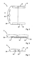
- Fig. 2
- eine stark vereinfachte Draufsicht auf einen Ausschnitt des Verdecks des Cabriolet-Fahrzeugs der
Fig. 1 , wobei eine in einem fahrzeugfrontseitigen Bereich an seitlichen Dachrahmen angeordnete Dachspitze ersichtlich ist; - Fig. 3
- eine stark vereinfachte Seitenansicht des Verdecks der
Fig. 2 , wobei eine als Kulisseneinrichtung ausgebildete Führungseinrichtung ersichtlich ist, mittels welcher die Dachspitze translatorisch gegenüber einem vorderen Dachrahmenteil des seitlichen Dachrahmens bewegbar ist; - Fig. 4
- eine Prinzipskizze eines alternativ ausgebildeten Verdecks in Seitenansicht, wobei eine Dachspitze mittels einer Viergelenkeinrichtung fahrzeugheckwärts gegenüber einem vorderen Dachrahmenteil von seitlichen Dachrahmen bewegbar ist;
- Fig. 5
- eine vereinfachte dreidimensionale Darstellung des Verdecks der
Figuren 1 bis 3 in Alleinstellung, wobei das Verdeck in einer Position dargestellt ist, welche zwischen der den Fahrgastraum schließenden Position und einer den Fahrgastraum freigebenden Position liegt; - Fig. 6
- eine dreidimensionale Darstellung des Verdecks der
Fig. 5 , wobei das Verdeck in der den Fahrgastraum freigebenden Position dargestellt ist; - Fig. 7
- eine stark vereinfachte schematische Seitenansicht des sich in der Ablageposition befindlichen Verdecks gemäß den
Figuren 5 und 6 - Fig. 8
- eine stark vereinfachte der
Fig. 2 entsprechende Darstellung des sich in seiner den Fahrgastraum freigebenden Position befindlichen Verdecks; - Fig. 9
- eine dreidimensionale Darstellung eines alternativ ausgebildeten Verdecks in einer den Fahrgastraum schließenden Position, wobei nur eine einer linken Fahrzeugseite zugeordnete Hälfte des Verdecks gezeigt ist;
- Fig. 10
- eine der
Fig. 9 entsprechende vereinfachte dreidimensionale Ansicht des Verdecks, wobei eine Dachspitze gegenüber vorderen Dachrahmenteilen heckwärts bewegt ist; - Fig. 11
- eine den
Figuren 9 und 10 - Fig. 12
- eine vereinfachte Ansicht des Verdecks der
Figuren 9 bis 11
- Fig. 1
- a simplified three-dimensional representation of a convertible vehicle with a top, which is shown in a passenger compartment closing position;
- Fig. 2
- a highly simplified plan view of a section of the hood of the convertible vehicle of the
Fig. 1 in which a rooftop arranged in a vehicle front area on lateral roof frames can be seen; - Fig. 3
- a greatly simplified side view of the hood of the
Fig. 2 , wherein a guide device designed as a link device is visible, by means of which the rooftop is translationally movable relative to a front roof frame part of the lateral roof frame; - Fig. 4
- a schematic diagram of an alternative design canopy in side view, with a roof top by means of a four-bar device vehicle rearward relative to a front roof frame part of lateral roof frames is movable;
- Fig. 5
- a simplified three-dimensional representation of the top of the
FIGS. 1 to 3 in isolation, wherein the canopy is shown in a position which is between the passenger compartment closing position and a position releasing the passenger compartment; - Fig. 6
- a three - dimensional representation of the top of the
Fig. 5 wherein the top is shown in the passenger compartment releasing position; - Fig. 7
- a highly simplified schematic side view of the located in the storage position hood according to the
FIGS. 5 and 6 ; - Fig. 8
- a greatly simplified the
Fig. 2 corresponding representation of the located in his passenger compartment releasing position hood; - Fig. 9
- a three-dimensional view of an alternatively formed canopy in a passenger compartment closing position, with only one of a left Vehicle side associated half of the hood is shown;
- Fig. 10
- one of the
Fig. 9 corresponding simplified three-dimensional view of the top, wherein a rooftop is moved rearward with respect to front roof frame parts; - Fig. 11
- a the
FIGS. 9 and 10 corresponding three-dimensional representation of the top, wherein the top is shown in an intermediate position between a closed position and a stored in a rear-side storage area position; and - Fig. 12
- a simplified view of the hood of the
FIGS. 9 to 11 wherein the top is shown in the stored in the rear storage area position.
In
Das verdeck 3 kann hierbei über eine in der
Zur Überführung des Verdecks 3 zwischen seiner geschlossenen und seiner offenen Position ist eine nicht näher dargestellte Antriebseinrichtung vorgesehen, welche hierzu mit einer als Verdeckgestänge 15 ausgebildeten Verdeckkinematik zusammenwirkt.For transferring the top 3 between its closed and its open position, a non-illustrated drive means is provided, which cooperates with this purpose designed as a
Das Verdeckgestänge 15 ist bei sich in geschlossener Position befindlichem Verdeck 3 in einem heckseitigen Bereich des Verdecks 3 an ein Hauptlager 17 angebunden und mit jeweils einer Fahrzeugsseite zugeordneten seitlichen Dachrahmen 19, 21 ausgebildet, wobei die seitlichen Dachrahmen 19, 21 im Wesentlichen baugleich ausgebildet sind und im Folgenden ein der linken Fahrzeugseite zugeordneter Dachrahmen 19 stellvertretend für einen der rechten Fahrzeugseite zugeordneten Dachrahmen 21 beschrieben wird.The convertible
Der seitliche Dachrahmen 19 ist vorliegend dreiteilig mit einem vorderen Dachrahmenteil 23 und zwei hinteren Dachrahmenteilen ausgebildet, wobei ein erstes hinteres Dachrahmenteil 25 bei sich in geschlossener Position befindlichem Verdeck 3 fahrzeugheckwärts an das vordere Dachrahmenteil 23 anschließt und ein zweites hinteres Dachrahmenteil 27 in geschlossener Position des Verdecks 3 eine C-Säule bildend heckwärts hinter dem ersten hinteren Dachrahmenteil 25 angeordnet ist.The
Die vorderen Dachrahmenteile 23 sind über eine Dachspitze 29 miteinander verbunden, welche gemäß der
Zur Festlegung des Verdecks 3 in geschlossener Position ist eine nicht näher dargestellte verriegelungsvorrichtung vorgesehen, welche mittels einer nur schematisch in der
Die bevorzugte Ausgestaltung der Erfindung weist den in
In
Das Verdeck 3 wird über die Antriebseinrichtung Z-artig zwischen der den Fahrgastraum 7 schließenden und der den Fahrgastraum freigebenden Position verfahren, d. h. sowohl die Dachspitze 29 als auch die vorderen Dachrahmenteile 23 weisen in der Ablageposition des Verdecks 3 dieselbe Orientierung wie in der geschlossenen Position des Verdecks 3 auf. Sowohl die Dachspitze 29 wie auch die vorderen Dachrahmenteile 23 erfahren dabei im Wesentlichen keine Drehung gegenüber einer Fahrzeugbodenebene und weisen jeweils mit derselben Fläche in Fahrzeughochrichtung, mit der sie auch bei den Fahrgastraum schließender Position des Verdecks 3 nach oben weisen.The top 3 is moved via the drive device Z-like between the passenger compartment 7 closing and releasing the passenger compartment position, d. H. Both the
Die ersten hinteren Dachrahmenteile 25 und die zweiten hinteren Dachrahmenteile 27 werden bei der Überführung des Verdecks 3 zwischen der den Fahrgastraum schließenden Position und der den Fahrgastraum 7 freigebenden Position um wenigstens annähernd 180° gegenüber der Fahrzeugbodenebene gedreht, so dass die ersten hinteren Dachrahmenteile 25 und die zweiten hinteren Dachrahmenteile 27 in ihrer Ablageposition eine entgegengesetzten Orientierung zu den vorderen Dachrahmenteillen 23 aufweisen. Eine Außenkontur bildende Krümmung der vorderen Dachrahmenteile 23 und der hinteren Dachrahmenteile 25, 27 ist in Ablageposition des Verdecks 3 somit gegengleich zueinander angeordnet.The first rear
Die Dachspitze 29 ist über eine nicht näher dargestellte Hebeleinrichtung an das Verdeckgestänge 15 gekoppelt, so dass die Dachspitze 29 während der Überführung des Verdecks 3 zwischen seiner den Fahrgastraum schließenden Position und seiner den Fahrgastraum 7 freigebenden Position zwangsgesteuert gegenüber dem vorderen Dachrahmenteil 23 bewegt wird.The
Die Zwangssteuerung ist dabei vorliegend derart ausgebildet, dass die Dachspitze 29 im Wesentlichen gleichmäßig über den gesamten Bewegungsablauf des Verdecks 3 verteilt gegenüber den seitlichen Dachrahmen 19, 21 bewegt wird. Ein separater Antrieb für die Bewegung der Dachspitze 29 gegenüber dem vorderen Dachrahmenteile 23 ist hierbei vorteilhafterweise nicht erforderlich.In this case, the positive control is embodied such that the
In den
In den
Wie insbesondere der
In den
Das Verdeck 45 ist auch hier mittels einer als Verdeckgestänge 47 ausgebildeten Verdeckkinematik über eine Anlenkung an einem Hauptlager 49 zwischen seiner geschlossenen und seiner offenen Position bewegbar.The top 45 is here also movable by means of a
Das Verdeckgestänge 47 weist jeweils einer Fahrzeugseite zugeordnet einen seitlichen Dachrahmen auf, wobei ein einer linken Fahrzeugseite zugeordneter seitlicher Dachrahmen 51 und ein nicht näher ersichtlicher, einer rechten Fahrzeugseite zugeordneter seitlicher Dachrahmen im Wesentlichen baugleich ausgebildet sind und der der linken Fahrzeugseite zugeordnete seitliche Dachrahmen 51 im Folgenden stellvertretend für den der rechten Fahrzeugseite zugeordneten seitlichen Dachrahmen beschrieben wird.The convertible
Der seitliche Dachrahmen 51 ist analog zu dem oben beschriebenen Ausführungsbeispiel dreiteilig mit einem vorderen Dachrahmenteil 55, einem ersten hinteren Dachrahmenteil 57 und einem zweiten Dachrahmenteil 59 ausgebildet.The
In einem in geschlossenem zustand des Verdecks 45 an dem Windschutzscheibenrahmen 9 angeordneten Bereich der vorderen Dachrahmenteile 55 sind die seitlichen Dachrahmen 51 über eine Dachspitze 61 miteinander verbunden. Heckwärts daran anschließend sind weitere die seitlichen Dachrahmen 51 in Fahrzeugquerrichtung verbindende Spriegel ausgebildet, wobei ein erster Spriegel 63 in einem fahrzeugheckseitigen Bereich der vorderen Dachrahmenteile 55, ein zweiter Spriegel 65 in einem heckseitigen Bereich der ersten hinteren Dachrahmenteile 57 und ein dritter Spriegel 67 in einem heckseitigen Bereich der zweiten hinteren Dachrahmenteile 59 angelenkt ist.In a region of the front
Bei einer Überführung des Verdecks 45 von seiner in der
Durch eine Weiterbewegung des Verdeckgestänges 47 über die Antriebseinrichtung wird das Verdeck 45 mit seinen seitlichen Dachrahmen 51 über die in der
In der Ablageposition des Verdecks 45 sind die seitlichen Dachrahmen 51 mit den vorderen Dachrahmenteilen 55, den ersten hinteren Dachrahmenteilen 57 und den zweiten hinteren Dachrahmenteilen 59 jeweils einer Fahrzeugseite zugewandt neben in den
Claims (10)
dadurch gekennzeichnet,
dass die Dachspitze (29, 61) zwischen ihrer im Bereich der Windschutzscheibenbegrenzung (9) angeordneten Position und ihrer Position bei geöffnetem Verdeck (3, 45) über den gesamten Bewegungsablauf mit einer Verdeckkinematik (15, 47) zwangsgekoppelt ist.Hood for a convertible vehicle (1) which can be moved between a passenger compartment (7) closing and a passenger compartment (7) releasing, in a rear-side storage area (13) arranged position, and which is associated with one side of the vehicle roof roofs ( 19, 21, 51) is formed, which with the top (3, 45) at least partially a vehicle side facing next to vehicle seats (37) stored in the rear storage area (13) and the top (3, 45) at a windshield boundary (9) are fixed; wherein the lateral roof frames (19, 21, 51) each form a front roof frame part (23, 55) and at least one rear roof frame part (25, 27, 55, 57), of which the front roof frame parts (23, 55) by means of a vehicle transverse direction extending rooftop (29, 61) are connected, which rests with the hood (3, 45) on the windshield boundary (9) and with the top (3, 45) relative to the front roof frame parts (23, 55) rearwardly displaced; and wherein the front roof frame parts (23, 55) in the in the rear storage area (13) stored top (3, 45) as well as the roof top (29, 61) unsuspected compared to their position with the roof closed (3, 45) in the rear storage space (13) are stored,
characterized,
that the roof peak (29, 61) between its in the region of the windscreen limitation (9) arranged position and its position when the top (3, 45) over the entire movement with a folding-top kinematics (15, 47) is positively coupled.
dass die Dachspitze (29, 61) mittels einer Führungseinrichtung (31, 33) gegenüber den vorderen Dachrahmenteilen (23, 55) bewegbar ist.Hood according to claim 1, characterized
that the roof peak (55 23) is movable (29, 61) by means of a guide means (31, 33) relative to the front roof frame parts.
dass die Führungseinrichtung als eine Kulisseneinrichtung (31) oder eine Viergelenkeinrichtung (33) ausgebildet ist.Hood according to claim 2, characterized
that the guide device is formed as a link-motion device (31) or a four-bar linkage means (33).
dadurch gekennzeichnet,
dass die Dachspitze (29, 61) über eine Hebeleinrichtung mit der verdeckkinematik (15, 47) zusammenwirkt.Hood according to one of claims 1 to 3,
characterized,
that the roof peak (29, 61) via a lever means with the top kinematics (15, 47) cooperates.
dadurch gekennzeichnet,
dass die seitlichen Dachrahmen (19, 21, 51) jeweils wenigstens dreiteilig mit insbesondere zwei hinteren Dachrahmenteilen (25, 27, 57, 59) ausgebildet sind.Hood according to one of claims 1 to 4,
characterized,
that the lateral roof frame are formed (19, 21, 51) each have at least three parts, with in particular two rear roof frame parts (25, 27, 57, 59).
dadurch gekennzeichnet,
dass die seitlichen Dachrahmen (19, 21, 51) jeweils wenigstens vierteilig mit insbesondere drei hinteren Dachrahmenteilen ausgebildet sind.Hood according to one of claims 1 to 5
characterized,
that the lateral roof frames (19, 21, 51) are each formed of at least four parts, with in particular three rear roof frame parts.
dadurch gekennzeichnet,
dass zwischen den seitlichen Dachrahmen (19, 21, 51) angeordnete Spriegel (63, 65, 67) bei in dem heckseitigen Ablagebereich (13) angeordnetem verdeck (3, 45) im Wesentlichen unterhalb der Dachspitze (29, 61) angeordnet sind.Hood according to one of claims 1 to 6,
characterized,
that between the lateral roof frame (19, 21, 51) arranged brackets (63, 65, 67) arranged in the rear-side storage area (13) top (3, 45) substantially below the roof top (29, 61) are arranged.
dadurch gekennzeichnet,
dass ein zur Spannung des Verdecks (3, 45) in Fahrzeuglängsrichtung bei sich in geschlossener Position befindlichem Verdeck (3, 45) vorgesehener Spannbügel (35) bei in dem heckseitigen Ablagebereich (13) angeordnetem verdeck (3, 45) im Wesentlichen unterhalb der Dachspitze (29, 61) angeordnet ist.Hood according to one of claims 1 to 7,
characterized,
in that a tensioning bow (35) provided for tensioning the convertible top (3, 45) in the vehicle in the closed position (3, 45) is provided below the roof top when the hood (3, 45) is arranged in the rear-side storage area (13) (29, 61) is arranged.
dadurch gekennzeichnet,
dass der heckseitige Ablagebereich (13) als ein heckseitiger Ablageraum ausgebildet ist, welcher insbesondere mittels einer Deckeleinrichtung (11) abschließbar ist.Hood according to one of claims 1 to 8,
characterized,
that the rear-side storage area (13) is formed as a rear stowage space, which is lockable in particular by means of a lid arrangement (11).
dadurch gekennzeichnet,
dass in der Dachspitze (29, 61) eine Verdeckverschlusseinheit angeordnet ist, die die Dachspitze (29, 61) bei geschlossenem Dach an der Windschutzscheibenbegrenzung (9) festlegt und die unabhängig von der Verdeckkinematik (15, 47) betätigbar ist.Hood according to one of claims 1 to 9,
characterized,
that in the roof top (29, 61) a Verdeckverschlusseinheit is arranged, which defines the roof top (29, 61) with the roof closed on the windshield boundary (9) and which is independently of the convertible top kinematics (15, 47) operable.
Applications Claiming Priority (1)
| Application Number | Priority Date | Filing Date | Title |
|---|---|---|---|
| DE102008022824A DE102008022824A1 (en) | 2008-05-08 | 2008-05-08 | Convertible top for a convertible vehicle with a rooftop that is movable in relation to the side roof frames |
Publications (2)
| Publication Number | Publication Date |
|---|---|
| EP2457757A1 true EP2457757A1 (en) | 2012-05-30 |
| EP2457757B1 EP2457757B1 (en) | 2013-07-10 |
Family
ID=40941714
Family Applications (1)
| Application Number | Title | Priority Date | Filing Date |
|---|---|---|---|
| EP20090006271 Active EP2457757B1 (en) | 2008-05-08 | 2009-05-08 | Cover for a convertible vehicle with a roof tip movable relative to lateral roof frames |
Country Status (2)
| Country | Link |
|---|---|
| EP (1) | EP2457757B1 (en) |
| DE (1) | DE102008022824A1 (en) |
Citations (4)
| Publication number | Priority date | Publication date | Assignee | Title |
|---|---|---|---|---|
| EP1080966A2 (en) * | 1999-09-06 | 2001-03-07 | Webasto Vehicle Systems International GmbH | Foldable top for convertible |
| DE10102643A1 (en) * | 2001-01-20 | 2002-07-25 | Bayerische Motoren Werke Ag | Folding top for motor vehicles has front hoop moved from closed into intermediate position to form sliding roof-sized opening in front seat area |
| DE10218463A1 (en) * | 2002-03-18 | 2003-12-04 | Edscha Cabrio Dachsys Gmbh | Folding top for convertible motor vehicle has front bow longitudinally movable on front roof frame section by means of linear guide and gear linkage which allows front bow to hinge upwards during opening action |
| DE102005015165A1 (en) | 2005-04-02 | 2006-10-05 | Wilhelm Karmann Gmbh | Convertible vehicle with a roof which can be secured to the windscreen frame |
Family Cites Families (6)
| Publication number | Priority date | Publication date | Assignee | Title |
|---|---|---|---|---|
| DE19801876A1 (en) * | 1998-01-20 | 1999-07-22 | Baur Engineering Gmbh | Private cabriolet vehicle with movable folding top |
| ATE473879T1 (en) * | 2002-10-18 | 2010-07-15 | Soc Europ Brevets Automobiles | DETACHABLE VEHICLE ROOF AND ASSOCIATED VEHICLE |
| DE10258052C5 (en) * | 2002-12-11 | 2008-06-12 | Magna Car Top Systems Gmbh | Adjustable vehicle roof for convertible vehicles |
| DE10344679B4 (en) * | 2003-09-25 | 2005-08-25 | Cts Fahrzeug-Dachsysteme Gmbh | Hardtop cabriolet vehicle roof, has servo kinematics arrangement connected between vehicle body and seven joint kinematics arrangement to adjust activity of front, rear and middle control guides |
| DE102005047846B3 (en) * | 2005-10-05 | 2006-10-26 | Cts Fahrzeug-Dachsysteme Gmbh | Vehicle roof for cabriolet vehicle with pivotable roof cap has cover rod with 2 lateral, multi-part roof frames that fold in transverse direction; roof cap is joined to lateral roof frames by rotary joint and pivots through 180 degrees |
| DE102006042288A1 (en) * | 2006-09-08 | 2008-03-27 | Dr.Ing.H.C. F. Porsche Ag | Folding hood with a top cloth attached to a frame handlebar |
-
2008
- 2008-05-08 DE DE102008022824A patent/DE102008022824A1/en not_active Withdrawn
-
2009
- 2009-05-08 EP EP20090006271 patent/EP2457757B1/en active Active
Patent Citations (5)
| Publication number | Priority date | Publication date | Assignee | Title |
|---|---|---|---|---|
| EP1080966A2 (en) * | 1999-09-06 | 2001-03-07 | Webasto Vehicle Systems International GmbH | Foldable top for convertible |
| DE10102643A1 (en) * | 2001-01-20 | 2002-07-25 | Bayerische Motoren Werke Ag | Folding top for motor vehicles has front hoop moved from closed into intermediate position to form sliding roof-sized opening in front seat area |
| DE10218463A1 (en) * | 2002-03-18 | 2003-12-04 | Edscha Cabrio Dachsys Gmbh | Folding top for convertible motor vehicle has front bow longitudinally movable on front roof frame section by means of linear guide and gear linkage which allows front bow to hinge upwards during opening action |
| DE10218463B4 (en) | 2002-03-18 | 2005-09-22 | Edscha Cabrio-Dachsysteme Gmbh | Hood for a convertible vehicle |
| DE102005015165A1 (en) | 2005-04-02 | 2006-10-05 | Wilhelm Karmann Gmbh | Convertible vehicle with a roof which can be secured to the windscreen frame |
Also Published As
| Publication number | Publication date |
|---|---|
| EP2457757B1 (en) | 2013-07-10 |
| DE102008022824A1 (en) | 2009-11-12 |
Similar Documents
| Publication | Publication Date | Title |
|---|---|---|
| DE102005043511B4 (en) | Cabriolet vehicle with retractable in a top compartment vehicle roof | |
| DE60122558T2 (en) | RETRACTABLE VEHICLE ROOF WITH SWIVEL ELEMENTS | |
| EP1331122B1 (en) | Retractable hardtop vehicle roof | |
| WO2005077693A1 (en) | Roof structure for a multi-purpose vehicle | |
| DE102005006435B4 (en) | Motor vehicle with an at least partially movable roof | |
| DE10258052B4 (en) | Adjustable vehicle roof for convertible vehicles | |
| DE102007032674A1 (en) | Moving roof for a passenger car | |
| DE102008006272A1 (en) | Convertible roof has two roof sections, where locking device is coupled for locking with enclosed roof to driving system, and is uncoupled during adjustment of roof in storage position of driving system | |
| DE102006052069B4 (en) | Passenger car with an open construction | |
| DE102010021400A1 (en) | Linkage flap assembly and vehicle with such a linkage flap assembly | |
| WO2008061578A1 (en) | Cover system for a convertible vehicle | |
| DE102009048353B4 (en) | Soft-top roof for a convertible vehicle | |
| EP2457757B1 (en) | Cover for a convertible vehicle with a roof tip movable relative to lateral roof frames | |
| DE102012113232B4 (en) | Cabriolet vehicle with a rear cover and a hood | |
| DE102007045829B4 (en) | Sunroof device for a motor vehicle and vehicle roof | |
| DE102008024917A1 (en) | Motor vehicle i.e. cabriolet, has openings in lining element serving for binding of rear mirror or form rear mirror, where entry of hand tool to outer skin parts which are moved is achieved via openings lined in outer skin parts | |
| DE102008063216A1 (en) | Hood of a convertible vehicle with at least two roof segments and a headliner | |
| DE102008046784A1 (en) | Covering device for use in e.g. cabriolet, has variable vehicle roof comprising movable roof element, which is laid down in one of two positions with vehicle roof in storage room in vehicle | |
| DE102007015704A1 (en) | Cabriolet vehicle, has roof secured against body in opening position by retaining device, and retaining device moved by actuating unit that is provided at windscreen sliding frame for opening or closing catch of roof part | |
| DE102008010414A1 (en) | Movable roof for structure of passenger car, has roof frames which are formed as roof side rails, where roof side rails are extended between upper cross beam of windscreen frame and rearward area of belt line of structure | |
| DE202008011624U1 (en) | Cabriolet vehicle with a hood | |
| DE10204663A1 (en) | Vehicle with selectively opening roof has front and rear roof parts which move in translation to open forwards and backwards respectively | |
| DE102008053333B4 (en) | convertible vehicle | |
| DE102007045791B4 (en) | Top module for a convertible vehicle with several fixed roof parts | |
| DE102006011144A1 (en) | Convertible motor vehicle with retractable roof-rear construction |
Legal Events
| Date | Code | Title | Description |
|---|---|---|---|
| PUAI | Public reference made under article 153(3) epc to a published international application that has entered the european phase |
Free format text: ORIGINAL CODE: 0009012 |
|
| AK | Designated contracting states |
Kind code of ref document: A1 Designated state(s): AT BE BG CH CY CZ DE DK EE ES FI FR GB GR HR HU IE IS IT LI LT LU LV MC MK MT NL NO PL PT RO SE SI SK TR |
|
| AX | Request for extension of the european patent |
Extension state: AL BA RS |
|
| 17P | Request for examination filed |
Effective date: 20120710 |
|
| GRAP | Despatch of communication of intention to grant a patent |
Free format text: ORIGINAL CODE: EPIDOSNIGR1 |
|
| RAP1 | Party data changed (applicant data changed or rights of an application transferred) |
Owner name: VALMET AUTOMOTIVE OY |
|
| GRAS | Grant fee paid |
Free format text: ORIGINAL CODE: EPIDOSNIGR3 |
|
| GRAA | (expected) grant |
Free format text: ORIGINAL CODE: 0009210 |
|
| AK | Designated contracting states |
Kind code of ref document: B1 Designated state(s): AT BE BG CH CY CZ DE DK EE ES FI FR GB GR HR HU IE IS IT LI LT LU LV MC MK MT NL NO PL PT RO SE SI SK TR |
|
| REG | Reference to a national code |
Ref country code: GB Ref legal event code: FG4D Free format text: NOT ENGLISH |
|
| REG | Reference to a national code |
Ref country code: AT Ref legal event code: REF Ref document number: 620750 Country of ref document: AT Kind code of ref document: T Effective date: 20130715 Ref country code: CH Ref legal event code: EP |
|
| REG | Reference to a national code |
Ref country code: IE Ref legal event code: FG4D Free format text: LANGUAGE OF EP DOCUMENT: GERMAN |
|
| REG | Reference to a national code |
Ref country code: DE Ref legal event code: R096 Ref document number: 502009007516 Country of ref document: DE Effective date: 20130905 |
|
| PG25 | Lapsed in a contracting state [announced via postgrant information from national office to epo] |
Ref country code: SI Free format text: LAPSE BECAUSE OF FAILURE TO SUBMIT A TRANSLATION OF THE DESCRIPTION OR TO PAY THE FEE WITHIN THE PRESCRIBED TIME-LIMIT Effective date: 20130710 |
|
| REG | Reference to a national code |
Ref country code: NL Ref legal event code: VDEP Effective date: 20130710 |
|
| REG | Reference to a national code |
Ref country code: LT Ref legal event code: MG4D |
|
| PG25 | Lapsed in a contracting state [announced via postgrant information from national office to epo] |
Ref country code: CY Free format text: LAPSE BECAUSE OF FAILURE TO SUBMIT A TRANSLATION OF THE DESCRIPTION OR TO PAY THE FEE WITHIN THE PRESCRIBED TIME-LIMIT Effective date: 20130828 Ref country code: SE Free format text: LAPSE BECAUSE OF FAILURE TO SUBMIT A TRANSLATION OF THE DESCRIPTION OR TO PAY THE FEE WITHIN THE PRESCRIBED TIME-LIMIT Effective date: 20130710 Ref country code: HR Free format text: LAPSE BECAUSE OF FAILURE TO SUBMIT A TRANSLATION OF THE DESCRIPTION OR TO PAY THE FEE WITHIN THE PRESCRIBED TIME-LIMIT Effective date: 20130710 Ref country code: IS Free format text: LAPSE BECAUSE OF FAILURE TO SUBMIT A TRANSLATION OF THE DESCRIPTION OR TO PAY THE FEE WITHIN THE PRESCRIBED TIME-LIMIT Effective date: 20131110 Ref country code: PT Free format text: LAPSE BECAUSE OF FAILURE TO SUBMIT A TRANSLATION OF THE DESCRIPTION OR TO PAY THE FEE WITHIN THE PRESCRIBED TIME-LIMIT Effective date: 20131111 Ref country code: LT Free format text: LAPSE BECAUSE OF FAILURE TO SUBMIT A TRANSLATION OF THE DESCRIPTION OR TO PAY THE FEE WITHIN THE PRESCRIBED TIME-LIMIT Effective date: 20130710 Ref country code: NO Free format text: LAPSE BECAUSE OF FAILURE TO SUBMIT A TRANSLATION OF THE DESCRIPTION OR TO PAY THE FEE WITHIN THE PRESCRIBED TIME-LIMIT Effective date: 20131010 |
|
| PG25 | Lapsed in a contracting state [announced via postgrant information from national office to epo] |
Ref country code: NL Free format text: LAPSE BECAUSE OF FAILURE TO SUBMIT A TRANSLATION OF THE DESCRIPTION OR TO PAY THE FEE WITHIN THE PRESCRIBED TIME-LIMIT Effective date: 20130710 Ref country code: ES Free format text: LAPSE BECAUSE OF FAILURE TO SUBMIT A TRANSLATION OF THE DESCRIPTION OR TO PAY THE FEE WITHIN THE PRESCRIBED TIME-LIMIT Effective date: 20131021 Ref country code: FI Free format text: LAPSE BECAUSE OF FAILURE TO SUBMIT A TRANSLATION OF THE DESCRIPTION OR TO PAY THE FEE WITHIN THE PRESCRIBED TIME-LIMIT Effective date: 20130710 Ref country code: LV Free format text: LAPSE BECAUSE OF FAILURE TO SUBMIT A TRANSLATION OF THE DESCRIPTION OR TO PAY THE FEE WITHIN THE PRESCRIBED TIME-LIMIT Effective date: 20130710 Ref country code: PL Free format text: LAPSE BECAUSE OF FAILURE TO SUBMIT A TRANSLATION OF THE DESCRIPTION OR TO PAY THE FEE WITHIN THE PRESCRIBED TIME-LIMIT Effective date: 20130710 Ref country code: GR Free format text: LAPSE BECAUSE OF FAILURE TO SUBMIT A TRANSLATION OF THE DESCRIPTION OR TO PAY THE FEE WITHIN THE PRESCRIBED TIME-LIMIT Effective date: 20131011 |
|
| PG25 | Lapsed in a contracting state [announced via postgrant information from national office to epo] |
Ref country code: CY Free format text: LAPSE BECAUSE OF FAILURE TO SUBMIT A TRANSLATION OF THE DESCRIPTION OR TO PAY THE FEE WITHIN THE PRESCRIBED TIME-LIMIT Effective date: 20130710 |
|
| PG25 | Lapsed in a contracting state [announced via postgrant information from national office to epo] |
Ref country code: DK Free format text: LAPSE BECAUSE OF FAILURE TO SUBMIT A TRANSLATION OF THE DESCRIPTION OR TO PAY THE FEE WITHIN THE PRESCRIBED TIME-LIMIT Effective date: 20130710 Ref country code: EE Free format text: LAPSE BECAUSE OF FAILURE TO SUBMIT A TRANSLATION OF THE DESCRIPTION OR TO PAY THE FEE WITHIN THE PRESCRIBED TIME-LIMIT Effective date: 20130710 Ref country code: RO Free format text: LAPSE BECAUSE OF FAILURE TO SUBMIT A TRANSLATION OF THE DESCRIPTION OR TO PAY THE FEE WITHIN THE PRESCRIBED TIME-LIMIT Effective date: 20130710 Ref country code: SK Free format text: LAPSE BECAUSE OF FAILURE TO SUBMIT A TRANSLATION OF THE DESCRIPTION OR TO PAY THE FEE WITHIN THE PRESCRIBED TIME-LIMIT Effective date: 20130710 Ref country code: CZ Free format text: LAPSE BECAUSE OF FAILURE TO SUBMIT A TRANSLATION OF THE DESCRIPTION OR TO PAY THE FEE WITHIN THE PRESCRIBED TIME-LIMIT Effective date: 20130710 |
|
| PLBE | No opposition filed within time limit |
Free format text: ORIGINAL CODE: 0009261 |
|
| STAA | Information on the status of an ep patent application or granted ep patent |
Free format text: STATUS: NO OPPOSITION FILED WITHIN TIME LIMIT |
|
| PG25 | Lapsed in a contracting state [announced via postgrant information from national office to epo] |
Ref country code: IT Free format text: LAPSE BECAUSE OF FAILURE TO SUBMIT A TRANSLATION OF THE DESCRIPTION OR TO PAY THE FEE WITHIN THE PRESCRIBED TIME-LIMIT Effective date: 20130710 |
|
| 26N | No opposition filed |
Effective date: 20140411 |
|
| REG | Reference to a national code |
Ref country code: DE Ref legal event code: R097 Ref document number: 502009007516 Country of ref document: DE Effective date: 20140411 |
|
| PG25 | Lapsed in a contracting state [announced via postgrant information from national office to epo] |
Ref country code: LU Free format text: LAPSE BECAUSE OF FAILURE TO SUBMIT A TRANSLATION OF THE DESCRIPTION OR TO PAY THE FEE WITHIN THE PRESCRIBED TIME-LIMIT Effective date: 20140508 |
|
| REG | Reference to a national code |
Ref country code: CH Ref legal event code: PL |
|
| PG25 | Lapsed in a contracting state [announced via postgrant information from national office to epo] |
Ref country code: CH Free format text: LAPSE BECAUSE OF NON-PAYMENT OF DUE FEES Effective date: 20140531 Ref country code: MC Free format text: LAPSE BECAUSE OF FAILURE TO SUBMIT A TRANSLATION OF THE DESCRIPTION OR TO PAY THE FEE WITHIN THE PRESCRIBED TIME-LIMIT Effective date: 20130710 Ref country code: LI Free format text: LAPSE BECAUSE OF NON-PAYMENT OF DUE FEES Effective date: 20140531 |
|
| REG | Reference to a national code |
Ref country code: IE Ref legal event code: MM4A |
|
| PG25 | Lapsed in a contracting state [announced via postgrant information from national office to epo] |
Ref country code: IE Free format text: LAPSE BECAUSE OF NON-PAYMENT OF DUE FEES Effective date: 20140508 |
|
| REG | Reference to a national code |
Ref country code: AT Ref legal event code: MM01 Ref document number: 620750 Country of ref document: AT Kind code of ref document: T Effective date: 20140508 |
|
| PG25 | Lapsed in a contracting state [announced via postgrant information from national office to epo] |
Ref country code: AT Free format text: LAPSE BECAUSE OF NON-PAYMENT OF DUE FEES Effective date: 20140508 |
|
| PG25 | Lapsed in a contracting state [announced via postgrant information from national office to epo] |
Ref country code: MT Free format text: LAPSE BECAUSE OF FAILURE TO SUBMIT A TRANSLATION OF THE DESCRIPTION OR TO PAY THE FEE WITHIN THE PRESCRIBED TIME-LIMIT Effective date: 20130710 |
|
| REG | Reference to a national code |
Ref country code: FR Ref legal event code: PLFP Year of fee payment: 8 |
|
| PG25 | Lapsed in a contracting state [announced via postgrant information from national office to epo] |
Ref country code: BG Free format text: LAPSE BECAUSE OF FAILURE TO SUBMIT A TRANSLATION OF THE DESCRIPTION OR TO PAY THE FEE WITHIN THE PRESCRIBED TIME-LIMIT Effective date: 20130710 |
|
| PG25 | Lapsed in a contracting state [announced via postgrant information from national office to epo] |
Ref country code: TR Free format text: LAPSE BECAUSE OF FAILURE TO SUBMIT A TRANSLATION OF THE DESCRIPTION OR TO PAY THE FEE WITHIN THE PRESCRIBED TIME-LIMIT Effective date: 20130710 Ref country code: HU Free format text: LAPSE BECAUSE OF FAILURE TO SUBMIT A TRANSLATION OF THE DESCRIPTION OR TO PAY THE FEE WITHIN THE PRESCRIBED TIME-LIMIT; INVALID AB INITIO Effective date: 20090508 Ref country code: BE Free format text: LAPSE BECAUSE OF FAILURE TO SUBMIT A TRANSLATION OF THE DESCRIPTION OR TO PAY THE FEE WITHIN THE PRESCRIBED TIME-LIMIT Effective date: 20140531 |
|
| REG | Reference to a national code |
Ref country code: FR Ref legal event code: PLFP Year of fee payment: 9 |
|
| PGFP | Annual fee paid to national office [announced via postgrant information from national office to epo] |
Ref country code: GB Payment date: 20170626 Year of fee payment: 9 |
|
| PGFP | Annual fee paid to national office [announced via postgrant information from national office to epo] |
Ref country code: FR Payment date: 20170727 Year of fee payment: 9 |
|
| PG25 | Lapsed in a contracting state [announced via postgrant information from national office to epo] |
Ref country code: MK Free format text: LAPSE BECAUSE OF FAILURE TO SUBMIT A TRANSLATION OF THE DESCRIPTION OR TO PAY THE FEE WITHIN THE PRESCRIBED TIME-LIMIT Effective date: 20130710 |
|
| GBPC | Gb: european patent ceased through non-payment of renewal fee |
Effective date: 20180508 |
|
| PG25 | Lapsed in a contracting state [announced via postgrant information from national office to epo] |
Ref country code: FR Free format text: LAPSE BECAUSE OF NON-PAYMENT OF DUE FEES Effective date: 20180531 Ref country code: GB Free format text: LAPSE BECAUSE OF NON-PAYMENT OF DUE FEES Effective date: 20180508 |
|
| P01 | Opt-out of the competence of the unified patent court (upc) registered |
Effective date: 20230601 |
|
| PGFP | Annual fee paid to national office [announced via postgrant information from national office to epo] |
Ref country code: DE Payment date: 20230720 Year of fee payment: 15 |