EP2457461B1 - Tätowierungsvorrichtung - Google Patents
Tätowierungsvorrichtung Download PDFInfo
- Publication number
- EP2457461B1 EP2457461B1 EP09847603.9A EP09847603A EP2457461B1 EP 2457461 B1 EP2457461 B1 EP 2457461B1 EP 09847603 A EP09847603 A EP 09847603A EP 2457461 B1 EP2457461 B1 EP 2457461B1
- Authority
- EP
- European Patent Office
- Prior art keywords
- cam
- link
- connecting rod
- driving motor
- needle
- Prior art date
- Legal status (The legal status is an assumption and is not a legal conclusion. Google has not performed a legal analysis and makes no representation as to the accuracy of the status listed.)
- Active
Links
Images




Classifications
-
- A—HUMAN NECESSITIES
- A45—HAND OR TRAVELLING ARTICLES
- A45D—HAIRDRESSING OR SHAVING EQUIPMENT; EQUIPMENT FOR COSMETICS OR COSMETIC TREATMENTS, e.g. FOR MANICURING OR PEDICURING
- A45D44/00—Other cosmetic or toiletry articles, e.g. for hairdressers' rooms
-
- A—HUMAN NECESSITIES
- A61—MEDICAL OR VETERINARY SCIENCE; HYGIENE
- A61M—DEVICES FOR INTRODUCING MEDIA INTO, OR ONTO, THE BODY; DEVICES FOR TRANSDUCING BODY MEDIA OR FOR TAKING MEDIA FROM THE BODY; DEVICES FOR PRODUCING OR ENDING SLEEP OR STUPOR
- A61M37/00—Other apparatus for introducing media into the body; Percutany, i.e. introducing medicines into the body by diffusion through the skin
- A61M37/0076—Tattooing apparatus
-
- A—HUMAN NECESSITIES
- A61—MEDICAL OR VETERINARY SCIENCE; HYGIENE
- A61M—DEVICES FOR INTRODUCING MEDIA INTO, OR ONTO, THE BODY; DEVICES FOR TRANSDUCING BODY MEDIA OR FOR TAKING MEDIA FROM THE BODY; DEVICES FOR PRODUCING OR ENDING SLEEP OR STUPOR
- A61M5/00—Devices for bringing media into the body in a subcutaneous, intra-vascular or intramuscular way; Accessories therefor, e.g. filling or cleaning devices, arm-rests
- A61M5/46—Devices for bringing media into the body in a subcutaneous, intra-vascular or intramuscular way; Accessories therefor, e.g. filling or cleaning devices, arm-rests having means for controlling depth of insertion
Definitions
- the present invention relates to a tattooing apparatus, and more particularly, to a tattooing apparatus, which repeatedly inserts and takes out a tattoo needle, which is driven to repeatedly travel back and forth by a driving of motor, into and from a skin thus to penetrate a pigment for tattoo into the skin.
- a tattooing apparatus is an apparatus, which represents a pattern or picture, such as signs, letters, and figures, on a skin of human by using a pigment for tattoo and a tattoo needle.
- US 2005/0010236 A1 discloses an apparatus for applying a tattoo or permanent make-up, comprising a disposable module removably arranged at a handpiece, a needle retained at one end in a needle shaft and supported for movement in a needle guide formed in the disposable module and at another end extending through a needle nozzle opening for discharge of color, and a drive mechanism composed of several structural members and coupled to the needle shaft to effect reciprocating movements of the needle, said plurality of structural members of the drive mechanism comprising drive and coupling means to couple the drive means to the needle shaft.
- US 6,033,421 concerns a handheld tattoo machine with a low vibration drive unit and an offset, removable driven grip tube.
- the drive unit includes a rotatable drive shaft; a cam attached to the distal end of the shaft, the cam having a cam face at an angle to the longitudinal axis of the drive shaft; and a drive housing enclosing the drive shaft and cam.
- the drive housing includes a driven grip tube receiving bore having a longitudinal axis parallel to and offset from the longitudinal axis of the drive housing to facilitate ease of use by the operator.
- the removable driven grip tube includes a reciprocal needle bar having a cam follower at a proximal end and a needle attachment surface at a distal end.
- EP 1 958 659 A1 discloses a drive module comprising a drive unit for producing a rotary movement and a transformation mechanism coupled to the drive unit to transform the drive movement into a forward/backward movement onto a needle unit for locally puncturing the skin and a freely moving functional component coupled to a magnetic locking piston which permits wobbling or pivoting of the functional component.
- a conventional tattooing apparatus is configured, so that the tattoo needle automatically travels back and forth and the pigment for tattoo rides the tattoo needle down while it travels back and forth.
- the tattoo needle moves while sticking at a given depth on the skin, a tattoo of given shape is represented on the skin as a practitioner intended.
- the conventional tattooing apparatus 1 includes upper and lower casings 1a and 1b forming the exterior, a driving motor 3 installed in the upper casing 1a, a driving axis 3a of the driving motor 3 on which a cam surface 5a with a tilt angle is formed, a rotation bar 5 installed in the lower casing 1b by a hinge H1 to be rotatable left and right within a certain range by the cam surface 5a according to the rotation of the driving axis 51, a straight moving bar 7 having a coupling end 7a projected from and formed at one end thereof and coupled with one end of the rotation bar 5 by a hinge H2 to reciprocate in a straight line according to the left and right rotation of the rotation bar 5, and a tattoo needle 9 coupled to the other end of the straight moving bar 7.
- the rotation bar 5 which repeatedly comes in contact with high and low surface portions of the cam surface 5a, is rotated left and right within the certain range, and thus the straight moving bar 7 reciprocates in the straight line to go in and out the tattoo needle 9 through a discharging hole on an lower end of the lower casing 1b.
- the conventional tattooing apparatus 1 as described above includes the separate rotation bar 5 for reciprocating the straight moving bar 7 in the straight line, the rotation of the rotation bar 5 synchronizes with the linear movement of the straight moving bar 7, thereby causing the tattooing apparatus to generate severe vibrations, which in turn make the practitioner difficult to extremelyly represent the tattoo.
- an aspect of the present invention is to provide a tattooing apparatus, which includes a cam link for offsetting a rotational inertia generated between a cam member and a connecting rod and and which can reduce vibrations and noises by minimizing a friction force generated between the cam member and the cam link.
- Another aspect of the present invention is to provide a tattooing apparatus, which can adjust an exposed length of a tattoo needle.
- FIG. 1 Another aspect of the present invention is to provide a tattooing apparatus, which can block vibrations generated by parts operated for driving a tattoo needle to reciprocate in a straight line therein from being transmitted to a casing.
- Another aspect of the present invention is to provide a tattooing apparatus, which can maintain a sturdy combination between a needle slider and a connecting rod when they are assembled and which can quickly separate the needle slider and the connecting rod from each other by a simple operation when they are disassembled.
- a tattooing apparatus according to claim 1.
- the bearing member is preferably made up of a pair of bearing members rotatably coupled to the pair of supporting protrusions, respectively, to come in rolling contact with upper and lower ends of a curved dam.
- a tattooing device according to claim 3 is provided.
- the bearing member is preferably disposed at one side of the cam link to come in rolling contact with the cam member and disposed at a rear end of the connecting rod to come in rolling contact with a front end of the cam link.
- a bearing is disposed between a connecting rod and a cam member, which are operated in connection with each other to enable a tattoo needle to reciprocate, to induce the connecting rod and the cam member to come in rolling contact with each other, thereby minimizing vibrations and noises generated in driving and loads transmitted to the driving motor due to friction force between the cam link and the cam member to prevent the driving motor from being lowered in driving output and to decrease power consumption thus to maximize usability.
- the body of the connecting rod which are operated in connection with each other to reciprocate the tattoo needle, is formed of a small tube, and at circumferences thereof, coaxially fitted with the anti-vibration tube, to prevent the vibrations from being transmitted to the casing and to enable the link to move straight, thereby causing no obstruction to the use of the tattooing apparatus due to the vibrations.
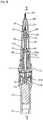
- FIG. 3 is a perspective view showing a tattooing apparatus according to an exemplary embodiment of the present invention
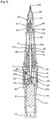
- FIG. 4 is a cross-sectional view taken along line A-A shown in FIG. 3
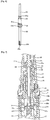
- FIG. 5 is a cross-sectional view taken along line B-B shown in FIG. 4
- FIG. 6 is an exploded perspective view showing a joint of the tattooing apparatus according to the exemplary embodiment of the present invention in a state before it is assembled
- FIG. 7 is an enlarged view showing main parts of FIG. 4
- FIG. 8 is an enlarged view showing main parts of FIG. 5
- FIG. 9 is an exploded perspective view showing according to the exemplary embodiment of the present invention.
- the tattooing apparatus includes a first casing 12, a second casing 13, an intermediate casing 14, upward and downward moving means 20, a connecting rod 30, a needle cartridge 50, and needle adjusting means 70.
- the first casing 12 is coupled to the needle cartridge 50, so that it accommodates the connecting rod 30, which drives to reciprocate a needle slider 53.
- the second casing 13 is coupled with the first casing 12, and accommodates the upward and downward moving means 20 having a cam structure for reciprocation of the connecting rod 30, and a driving motor 17.
- the intermediate casing 14 provides a rotation groove 14b disposed in a connection portion between the first and the second casings 12 and 13 and having one side to which a rotation nut 71 forming the needle adjusting means 70 is rotataby coupled.
- the intermediate casing 14 allows the connecting rod 30 to pass therethrough and at the same time, supports the connecting rod 30 to be slidable.
- the upward and downward moving means 20 includes a fixing tube 21, a cam member 23, a curved dam 24, and a cam link 27.
- the fixing tube 21 is fixedly disposed in the intermediate casing 14, and has an upward and downward guiding groove 22 formed at an inner circumferential surface thereof to guide the cam link 27 to move up and down.
- the cam member 23 at a front end thereof has a cam plate 23a inclined to one side and at a rear end thereof is coupled with a driving axis 17a of the driving motor 17 to rotate according to a driving of the driving motor 17.
- the curved dam 24 is formed at and projected from a predetermined height above and below along an edge of the cam plate 23a, and upper and lower ends of the curved dam 24 is in point contact with upper and lower link bars 27b and 27c therebetween.
- the cam link 27 includes the upper and the lower link bars 27b and 27c, which slidably move along a surface of the curved dam 24, and a square-shaped link column 27a, which integrally combines the upper and the lower link bars 27b and 27c.
- the upper link bar 27b at one end thereof has hinge protrusions 27d projected from both sides thereof and fitted in and with a lower end of the connecting rod 30.
- the link column 27a is preferably formed of a square column or a oval column, so that it can move up and down, but cannot rotate.
- the cam link 27 travels at a predetermined distance up and down as the upper and the lower link bars 27b and 27c move up and down along the surface of the curved dam 24 when the cam member 23 rotates.
- the connecting rod 30 has a body formed of a hollowed tube, and has a structure with a joint 31, which is hooked and coupled with one end of the needle slider 53 to be capable of being assembled therewith and separated therefrom.
- an anti-vibration tube 40 is disposed to wrap an outer side of the connecting rod 30, and thus guides an upward and downward linear movement of the connecting rod 30 between the connecting rod 30 and the intermediate casing 14.
- anti-vibration packings 41 are fitted to an outer surface of the anti-vibration tube 40 and an inner surface of the intermediate casing 14 therebetween to prevent vibrations and slips therebetween.
- first and second coil springs S1 and S2 are disposed on an upper side of the connecting rod 30 and an upper end of the cam link 27, respectively.
- the first coil spring S1 absorbs impacts due to inertia when the link mechanism is moved in a backward direction
- the second coil spring S2 absorbs impacts due to inertia when the link mechanism is moved in a forward direction, thereby reducing vibrations and noises.
- the joint 31 includes an elongated rectangular joint hole 31a in which a hanging hook 55 projected from both sides of a lower end of the needle slider 53 is accommodated, and a hook hole 31b formed to penetrate a side of the joint hole 31a thus to allow the hanging hook 55 to be fitted therein when it rotates at an angle of 90 degrees along with the needle slider 53 as it penetrates the side of the joint hole 31a along with the needle slider 53.
- the connecting rod 30 has a slit 30a formed at a lower end thereof to make side walls 30c face parallel to each other, and hinge holes or grooves 39b in which the hinge protrusions 27d are fitted are formed on the facing side walls 30c.
- the needle cartridge 50 is provided with the tattoo needle 60, and the needle slider 53 to drive the tattoo needle 60.
- the needle adjusting means 70 connects the first casing 12 and the second casing 13, and as it rotates clockwise and cunterclockwise, adjusts a degree where the tattoo needle 60 is projected from the first casing 12 by changing a coupling length between the first and the second casings 12 and 13 to allow the first casing 12 to approach the second casing 13 or move away from the second casing 13
- the needle adjusting means 70 as described above further include an inner nut 73 screwed coaxial with the rotation nut 71 on an outer surface of the intermediate casing 14.
- the inner nut 73 has a stopper 73a for maintaining rotation and constant positions of the rotation nut 71, which is projected outward at a lower end thereof.
- a threaded adjusting portion 12a of a rear end 12b of the first casing 12 is screwed with the rotation nut 71 in a space 71a between the inner nut 73 and the rotation nut 71.
- the hanging hook 55 which is a lower end of the needle slider 53, is lowered toward the joint hole 31a, as shown in FIG. 6 .
- a cartridge body 51 is rotated at an angle of 90 degrees and thus the hanging hook 55 is hooked and coupled in the hook hole 31b to be fitted therein.
- the first casing 12 and the needle cartridge 50 coupled thereto which guide to take out the tattoo needle 60 at a certain projected or taken-out length, are adjusted in length by the needle adjusting means 70. This acts to reduce and increase the tattoo needle 60 in length.
- the threaded adjusting portion 12a acts to increase the first casing 12 in length, instead of moving the rotating rotation nut 71, while being unscrewed. Accordingly, this means that the exposed length of the tattoo needle 60 is reduced.
- the tattooing apparatus can combine various models by using one, thereby bringing economical benefit.
- the tattooing apparatus of the exemplary embodiment of the present invention is configured, so that the curved dam 24 curved above and below is formed at the edge of the cam plate 23a to allow upper and lower portion thereof to be driven in point contact with the upper and the lower link bars 27b and 27c and thus to allow the cam link 27 to exert an upward and downward action, which applies a reciprocating movement to the needle slider 53 and the tattoo needle 60 through the connecting rod 30, thereby reducing the driving motor 17 in load to decrease power consumption and removing noises.
- the cam link 27 is formed of a rectangular or oval shape, so that it is always moved up and down without being rotated, thereby providing stability and good assembling ability.
- the hinge protrusions 27d are exposed at both sides of the upper end of the upper link bar 27b, and fitted in the hinge grooves 30b of the side walls 30c separated from to each other by the slit 30a, so that the side walls 30c and the hinge protrusions 27d are not separated from each other, but moved up and down in a body.
- the upper link bar 27b is fitted in the slit 30a of same size, and in assembling, the slit 30a is spread a little to allow the hinge protrusions 27d to be coupled in the hinge grooves 30b.
- the hinge protrusions 27d assembled remains as it is, and the upper link bar 27b maintains a state where it is in contact with an inner surface of the slit 30a not to be separated from the slit 30a in use, thereby continuing stable action.
- the tattooing apparatus of the exemplary embodiment of the present invention is configured, so that the body of the connecting rod 30 is formed of a tube of small diameter and at circumferences thereof, fitted with the anti-vibration tube 40, and the anti-vibration tube 40 is coupled with the intermediate casing 14 through the anti-vibration packings 41 in a state where it prevents the inner surface of the intermediate casing 14 from generating slips and where it allows the inner surface of the intermediate casing 14 to absorb vibrations, thereby enabling the connecting rod 30 to move straight and at the same time, absorbing impact vibrations through the anti-vibration tube 40 and the anti-vibration packings 41 twice over to prevent the vibrations from being transmitted even to the first casing 12 and thus to maximize using sensitivity of the user and remove noises due to the vibrations.
- a threaded inner nut-fixing portion 14a is formed on the intermediate casing 14 to coaxially assemble the inner nut 73 with the rotation nut 71.
- a stopper 73a is projected from the inner nut 73, so that it blocks the rotation nut 71 seated in the rotation groove 14b from moving to the first casing 12 and so that in disassembling, the rotation nut 71 is unscrewed to first separate the first casing 12 and then the inner nut 73 is unscrewed to separate the rotation nut 71 from the intermediate nut 14, thereby allowing the tattooing apparatus to be assembled and disassembled.
- the rear end 12b of the first casing 12 is disposed in the space 71a between the inner but 73 and the rotation nut 71, and is screwed with the rotation nut 71 by the threaded adjusting portion 12a to be coupled at the inner and outer surface of the first casing 12, thereby maximizing coupling force therebetween.
- the tattooing apparatus of the exemplary embodiment of the present invention has been explained based on penetrating a tattoo ink for tattoo into the skin through the tattoo needle, it can be also used for injecting an injectable solution or a drug into the skin.
- cam link 27 as described above has been illustrated as being in direct point contact with the curved dam 24 of the cam member 23, the present invention is not limited thereto, and bearings are disposed on contact portions between the cam link 27 and the cam member 23 to minimize a friction force between the cam link 27 and the cam member 23.
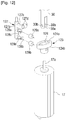
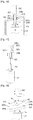
- FIGS. 10 to 12 are a side elevation, a cross-sectional view, and an exploded perspective view showing an example wherein roller bearings are employed in the cam link of the present invention, respectively.
- the cam link 127 at an upper part thereof is formed the upper link bar 127b, which is hinged with the connecting rod 30.
- a pair of supporting protrusions 128a and 128b is projected approximately perpendicular to a longitudinal direction of the cam link 127 while spacing down from the upper link bar 127b, and roller bearings 129a and 129b are snapped and coupled on the supporting protrusions 128a and 128b, respectively.
- hanging jaws 128c and 128d are formed on end tips of the pair of supporting protrusions 128a and 128b to prevent the roller bearings 129a and 129b from being released from the pair of supporting protrusions 128a and 128b, respectively.
- the pair of roller bearing 129a and 129b is rotatably coupled on the supporting protrusions 128a and 128b, and a portion of the curved dam 124 of the cam member 123 is inserted between the pair of roller bearing 129a and 129b.
- the cam member 123 is rotated according to the driving of the driving motor 17, the upper and the lower ends 124a and 124b of the curved dam 124 are slid in a state where they come in contact with the pair of roller bearing 129a and 129b, respectively. According to this, the friction force generated between the cam member 123 and the cam link 127 can be minimized, thereby greatly reducing the vibrations and the noises and at the same time, minimizing driving output of the driving motor 17.
- FIGS. 13 to 15 are a side elevation, a cross-sectional view, and an exploded perspective view showing an example where the roller bearings are employed in the cam link of the present invention, respectively.
- the cam link 227 at an upper part thereof is formed the upper link bar 227b, which is hinged with the connecting rod 30.
- a pair of supporting protrusions 228a and 228b is projected approximately perpendicular to a longitudinal direction of the cam link 227 while spacing down from the upper link bar 227b.
- Recessed grooves 228c and 228d are formed on inner sides of the pair of supporting protrusions 228a and 228b in a direction facing each other, and the ball bearings 229a and 229b are rotatably inserted in the recessed grooves 228a and 228b, respectively.
- a stopper 228f roratably supports the pair of ball bearings 229a and 229b in a state where it is inserted into an inserting hole 228e.
- a portion of the curved dam 124 of the cam member 123 is inserted between the pair of roller bearing 229a and 229b. If the cam member 123 is rotated according to the driving of the driving motor 17, the upper and the lower ends 124a and 124b of the curved dam 124 are slid in a state where they come in contact with the pair of roller bearing 229a and 229b, respectively. As a result, like in case of employing the roller bearings 129a and 129b, the friction force generated between the cam member 123 and the cam link 227 can be minimized, thereby greatly reducing the vibrations and the noises and at the same time, minimizing driving output of the driving motor 17.
- the cam structure of the present invention may be constructed in various ways, and in this case, the bearings can be also employed to components, which comes in sliding contact with the cam member, thereby minimizing the vibrations and the noises.
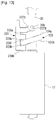
- a cam structure shown in FIGS. 16 and 17 is configured, so that the driving axis 17a of the driving motor 17 is inserted an inserting groove 328 formed on a rear end of a cam link 328.
- the driving axis 17a and the inserting groove 328 are cut out at one side thereof, so that when the driving axis 17a rotates, the cam link 327 rotates along with he driving axis 17a and at the same time, moves back and forth along an axial direction of the driving axis 17a.
- a connecting rod 330 is disposed on the same axial line as the cam link 327, and a pair of supporting protrusions 327b and 327c is formed at one side of the cam link 327 in the same direction.
- the pair of supporting protrusions 327b and 327c has roller bearings 329a and 329b rotatably installed thereon, respectively.
- ball bearings may be also applied.
- a ball bearing 331 installed on a rear end of the connecting rod 330 is disposed in contact with a front end of the cam link 327, the cam link 327 and the connecting rod 330 come in rolling contact with each other.
- a cam member 323 is disposed to incline to one side, and at a middle thereof is formed a penetrated hole 325 through which the cam link 327 passes. Also, the cam member 324 is fixedly installed in the intermediate casing 14.
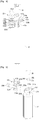
- cam structure is provided with a cam member 423 in the form of approximately plate, which is inclined to one side and a center of which is coupled with the driving axis 17a of the driving motor 17. Further, a cam link 427 is disposed between the connecting rod 430 and the cam member 423.
- the cam link 427 at a middle thereof is coupled to the fixing tube 21 (see FIG. 5 ) by a hinge H1 to coincide with a line of center axis of the driving axis 17a and at one side thereof is coupled to the connecting rod 430 by a hinge H2.
- the cam link 420 has a pair of extended portions 427a and 427b bent toward the cam member 423 from both sides thereof.
- the pair of extended portions 427a and 427b has ball bearings 429a and 429b installed on portions where they comes in contact with the cam member 423.
- cam structure is provided with a cam member 523 in the form of approximately plate, which is inclined to one side and a center of which is coupled with the driving axis 17a of the driving motor 17, like the cam structure shown in FIG. 18 .
- a cam link 527 at an approximately middle thereof is coupled to the fixing tube 21 (see FIG. 5 ) by a hinge H and at a lower end thereof is in contact with an upper surface of the cam member 523 through a ball bearing 529. Further, the cam link 527 at a front end thereof is in contact with a connecting rod 530 through another ball bearing 531 installed on a rear end of the connecting rod 530.
- the cam link 527 is disposed in a rolling contact with the cam member 523 and the connecting rod 530 therebetween through the ball bearings 529 and 531. Accordingly, even in case of the cam structure shown in FIG. 19 , vibrations and noises can be reduced and a lowering in driving output can be prevented.
Landscapes
- Health & Medical Sciences (AREA)
- Engineering & Computer Science (AREA)
- Animal Behavior & Ethology (AREA)
- General Health & Medical Sciences (AREA)
- Medical Informatics (AREA)
- Anesthesiology (AREA)
- Biomedical Technology (AREA)
- Heart & Thoracic Surgery (AREA)
- Hematology (AREA)
- Life Sciences & Earth Sciences (AREA)
- Virology (AREA)
- Dermatology (AREA)
- Public Health (AREA)
- Veterinary Medicine (AREA)
- Transmission Devices (AREA)
- Infusion, Injection, And Reservoir Apparatuses (AREA)
- Tires In General (AREA)
- Sewing Machines And Sewing (AREA)
- Press Drives And Press Lines (AREA)
- Forging (AREA)
Claims (3)
- Tätowierungsvorrichtung, umfassend:eine Tätowiernadel (60) undAufwärts- und Abwärtsverschiebungsmittel (20) zur Übertragung einer Drehkraft eines Antriebsmotors auf die Tätowiernadel (60),wobei die Aufwärts- und Abwärtsverschiebungsmittel (20) aus einer Nockenstruktur zur Umwandlung einer Rotation durch eine Drehkraft des Antriebsmotors (17) in eine lineare Bewegung bestehen und ein Lagerelement (129a, 129b, 229a, 229b) für einen Rollkontakt zum Reduzieren von Schwingungen und Geräuschen umfassen,wobei die Aufwärts- und Abwärtsverschiebungsmittel umfassen:ein Nockenelement (23, 123) mit einer einer Seite zugeneigten Kurvenscheibe (23, 123a), wobei die Kurvenscheibe durch den Antriebsmotor rotierbar ist;eine Verbindungsstange (30) zur Übertragung einer Kraft auf die Tätowiernadel undeine Nockenverbindung (27) zum Hin- und Herfahren in Verbindung mit der Rotation des Nockenelements, um so die Kraft auf die Verbindungsstange zu übertragen, dadurch gekennzeichnet, dass:wobei das Lagerelement (129a, 129b, 229a, 229b) auf einer Seite der Nockenverbindung angeordnet ist, um in Rollkontakt mit den oberen und unteren Enden der einen Seite der Kurvenscheibe (23a, 123a) zu kommen, undwobei die Nockenverbindung umfasst:eine Verbindungssäule (27a, 127a);eine auf einer Seite der Verbindungssäule hervorstehende obere Verbindungsschiene (27b, 127b, 227b), die mit einem Ende der Verbindungsstange gelenkig verbunden ist; undein Paar tragender Vorsprünge (128a, 128b, 228a, 22b), die auf einer Seite der Verbindungssäule (27a) hervorstehen und voneinander beabstandet sind, um die Einführung einer Seite der Kurvenscheibe zu ermöglichen.
- Vorrichtung nach Anspruch 1, wobei das Lagerelement (129a, 129b, 229a, 229b) ein Paar Lagerelemente umfasst, die rotierbar mit dem Paar unterstützender Vorsprünge gekoppelt ist, um in Rollkontakt mit den oberen und unteren Enden eines gekrümmten Damms (124) zu kommen.
- Tätowierungsvorrichtung, umfassend:eine Tätowiernadel (60) undAufwärts- und Abwärtsverschiebungsmittel (20) zur Übertragung einer Drehkraft eines Antriebsmotors (17) auf die Tätowiernadel (60),wobei die Aufwärts- und Abwärtsverschiebungsmittel aus einer Nockenstruktur zur Umwandlung einer Rotation durch eine Drehkraft des Antriebsmotors (17) in eine lineare Bewegung bestehen und ein erstes Lagerelement (329a, 329b) und ein zweites Lagerelement (331) für einen Rollkontakt zum Reduzieren von Schwingungen und Geräuschen umfassen, undeine Verbindungsstange (330) zur Übertragung einer Kraft auf die Tätowiernadel;wobei die Aufwärts- und Abwärtsverschiebungsmittel umfassen:
ein einer Seite zugeneigtes Nockenelement (324), dadurch gekennzeichnet, dass die Aufwärts- und Abwärtsverschiebungsmittel ferner umfassen:eine Nockenverbindung (327), die derart angeordnet ist, dass sie das Nockenelement durchquert, und ein hinteres Ende umfasst, das koaxial mit einer Antriebsachse des Antriebsmotor (17) verschiebbar eingeführt wird, um mit der Antriebsachse in Verbindung mit einer Rotation der Antriebsachse zu rotieren, um so Kraft auf die Verbindungsstange zu übertragen, die wiederum die Kraft auf die Tätowiernadel überträgt,wobei das erste Lagerelement (329a, 329b) auf einer Seite der Nockenverbindung angeordnet ist, um in Rollkontakt mit dem Nockenelement zu kommen, und das zweite Lagerelement (331) ein Kugellager ist, das an einem hinteren Ende der Verbindungsstange angeordnet ist, um in Rollkontakt mit einem vorderen Ende der Nockenverbindung zu kommen.
Priority Applications (3)
| Application Number | Priority Date | Filing Date | Title |
|---|---|---|---|
| PL13179093T PL2659803T3 (pl) | 2009-07-22 | 2009-08-05 | Urządzenie do tatuowania |
| PL09847603T PL2457461T3 (pl) | 2009-07-22 | 2009-08-05 | Urządzenie do tatuowania |
| EP13179093.3A EP2659803B1 (de) | 2009-07-22 | 2009-08-05 | Tätowierungsvorrichtung |
Applications Claiming Priority (2)
| Application Number | Priority Date | Filing Date | Title |
|---|---|---|---|
| KR1020090066801A KR101150777B1 (ko) | 2009-07-22 | 2009-07-22 | 문신장치 |
| PCT/KR2009/004373 WO2011010764A1 (ko) | 2009-07-22 | 2009-08-05 | 문신장치 |
Related Child Applications (2)
| Application Number | Title | Priority Date | Filing Date |
|---|---|---|---|
| EP13179093.3A Division EP2659803B1 (de) | 2009-07-22 | 2009-08-05 | Tätowierungsvorrichtung |
| EP13179093.3A Division-Into EP2659803B1 (de) | 2009-07-22 | 2009-08-05 | Tätowierungsvorrichtung |
Publications (3)
| Publication Number | Publication Date |
|---|---|
| EP2457461A1 EP2457461A1 (de) | 2012-05-30 |
| EP2457461A4 EP2457461A4 (de) | 2013-02-13 |
| EP2457461B1 true EP2457461B1 (de) | 2018-10-10 |
Family
ID=43499231
Family Applications (2)
| Application Number | Title | Priority Date | Filing Date |
|---|---|---|---|
| EP09847603.9A Active EP2457461B1 (de) | 2009-07-22 | 2009-08-05 | Tätowierungsvorrichtung |
| EP13179093.3A Active EP2659803B1 (de) | 2009-07-22 | 2009-08-05 | Tätowierungsvorrichtung |
Family Applications After (1)
| Application Number | Title | Priority Date | Filing Date |
|---|---|---|---|
| EP13179093.3A Active EP2659803B1 (de) | 2009-07-22 | 2009-08-05 | Tätowierungsvorrichtung |
Country Status (9)
| Country | Link |
|---|---|
| US (1) | US9114239B2 (de) |
| EP (2) | EP2457461B1 (de) |
| KR (1) | KR101150777B1 (de) |
| CN (2) | CN102469866B (de) |
| ES (2) | ES2536733T3 (de) |
| PL (2) | PL2457461T3 (de) |
| RU (1) | RU2528971C2 (de) |
| TR (1) | TR201819759T4 (de) |
| WO (1) | WO2011010764A1 (de) |
Families Citing this family (53)
| Publication number | Priority date | Publication date | Assignee | Title |
|---|---|---|---|---|
| KR101395100B1 (ko) * | 2012-12-21 | 2014-05-19 | 방시열 | 피부시술장치 |
| TW201509471A (zh) | 2013-04-10 | 2015-03-16 | Sanofi Sa | 注射裝置(十一) |
| US9126027B2 (en) * | 2013-05-30 | 2015-09-08 | Mei-Chi-Na-Hsinyen Co., Ltd. | Eyebrow tattoo machine capable of activating both swinging movement and up-and-down movement |
| FR3009500B1 (fr) * | 2013-08-08 | 2015-09-25 | Jean Pierre Bellmann | Appareil de tatouage |
| EP3041549B1 (de) * | 2013-09-05 | 2019-02-20 | Sanofi-Aventis Deutschland GmbH | Antriebsmechanismus für eine nadeleinführungsanordnung |
| EP3041527B1 (de) * | 2013-09-05 | 2018-05-09 | Sanofi-Aventis Deutschland GmbH | Antriebsmechanismus für eine anordnung zum einführen einer nadel |
| WO2015084475A1 (en) | 2013-12-04 | 2015-06-11 | Medmetics, Llc | Skin puncturing device |
| US9393395B2 (en) * | 2014-01-21 | 2016-07-19 | Michael Chen | Tattoo machine |
| EP3137129B1 (de) | 2014-04-28 | 2021-03-10 | Emory University | Systeme zur gewebebehandlung |
| US9750528B2 (en) * | 2014-06-12 | 2017-09-05 | MT. DERM GmbH | Handheld device for repeated puncture of human or animal skin |
| US9827409B1 (en) * | 2015-02-06 | 2017-11-28 | Inline Tattoo Machines, Llc | Electronic tattooing device and method |
| CN104784044B (zh) * | 2015-05-12 | 2017-03-01 | 京东方科技集团股份有限公司 | 一种针灸装置 |
| USD805195S1 (en) * | 2015-08-26 | 2017-12-12 | Bomtech Electronics Co., Ltd. | Tattooing apparatus |
| US11020203B2 (en) * | 2015-09-09 | 2021-06-01 | Rejuvatek Medical Inc. | System for puncturing the epidermis with controlled fluid delivery |
| DE102015117017A1 (de) * | 2015-10-06 | 2017-04-06 | Krones Ag | Vorrichtung und Verfahren zum Umformen von Kunststoffvorformlingen zu Kunststoffbehältnissen mit Kopplungseinrichtung |
| KR101593617B1 (ko) * | 2015-11-10 | 2016-02-12 | 권승열 | 반영구 화장 및 문신용 니들 또는 약물 침투용 니들을 전후 왕복이동시키는 다목적 멀티 니들 구동 머신장치 |
| USD805197S1 (en) * | 2015-11-30 | 2017-12-12 | Bomtech Electronics Co., Ltd. | Tattooing apparatus |
| USD805640S1 (en) * | 2015-12-16 | 2017-12-19 | Jong Dae Lee | Needle cartridge for a tattooing apparatus |
| USD805196S1 (en) * | 2016-03-10 | 2017-12-12 | Bomtech Electronics Co., Ltd. | Tattooing apparatus |
| USD805198S1 (en) * | 2016-03-22 | 2017-12-12 | Bomtech Electronics Co., Ltd | Tattooing apparatus |
| US10220195B2 (en) | 2016-06-08 | 2019-03-05 | Eclipse Medcorp, Llc | Radio frequency needling device for use with disposable needle cartridges |
| US9629991B1 (en) | 2016-06-08 | 2017-04-25 | Eclipse Aesthetics, LLC | Disposable radio frequency needle cartridges having absorbing containment barriers |
| US9636491B1 (en) | 2016-06-08 | 2017-05-02 | Eclipse Aesthetics, LLC | Disposable needle cartridges having absorbing contaminant barriers |
| KR101840320B1 (ko) | 2016-07-28 | 2018-03-20 | 성지건설 주식회사 | 문신장치 |
| US10744312B2 (en) * | 2016-08-24 | 2020-08-18 | Fk Irons Inc. | Tattoo machine grip apparatus |
| US11260209B2 (en) * | 2016-08-24 | 2022-03-01 | Fk Irons Inc. | Pen style microneedling machine apparatus |
| AT518780B1 (de) * | 2016-10-13 | 2018-01-15 | Blackgold - Highend Tätowiersysteme Og | Handgerät zum Tätowieren |
| US10960193B1 (en) * | 2017-02-17 | 2021-03-30 | Mark A. Reeves | Swiveling tattoo needle |
| KR101937145B1 (ko) | 2017-04-18 | 2019-01-10 | 박용택 | 문신장치용 바늘유닛 |
| US10806915B2 (en) * | 2017-08-30 | 2020-10-20 | Long Xiao | Devices for applying coloured liquid to skin |
| JP1618922S (de) * | 2017-09-28 | 2018-11-26 | ||
| KR102201041B1 (ko) * | 2018-10-02 | 2021-01-08 | 박용택 | 문신작업 모니터링을 위한 문신 시스템 |
| US11400268B2 (en) | 2018-10-11 | 2022-08-02 | Fk Irons Inc. | Electromagnetically driven tattoo machine and system |
| CN109481034B (zh) * | 2018-12-18 | 2022-08-23 | 中国人民解放军第四军医大学 | 手术室寻针装置 |
| USD909673S1 (en) * | 2019-02-13 | 2021-02-02 | Pujiang Solong Intelligent Technology Co., Ltd. | Permanent makeup pen |
| US11406807B2 (en) | 2019-03-27 | 2022-08-09 | Fk Irons Inc. | Tattoo machine rechargeable battery unit with voltage controller |
| EP3725358B1 (de) * | 2019-04-15 | 2023-09-13 | MT.DERM GmbH | Antriebssystem und antriebsmodul für ein handgerät zum lokalen aufstechen einer menschlichen oder einer tierischen haut sowie handgerät |
| CA3164957A1 (en) * | 2019-12-09 | 2021-06-17 | Carson HILL | Variable frequency waveform tattoo needle mechanism |
| US11642507B2 (en) | 2020-12-14 | 2023-05-09 | Black Claw LLC | Needle modules and associated methods |
| CN114129821B (zh) * | 2020-12-21 | 2024-03-19 | 艾诺克医美科技(珠海)有限公司 | 高精度控制出针长度的多针注射针头 |
| EP4291284A4 (de) | 2021-02-12 | 2025-02-12 | FK Irons Inc. | Adaptervorrichtung für eine tätowiermaschine |
| USD1060666S1 (en) | 2021-02-12 | 2025-02-04 | Fk Irons Inc. | Combined adapter device and grip for a tattoo machine |
| USD1025357S1 (en) | 2021-09-30 | 2024-04-30 | Fk Irons Inc. | Tattoo machine |
| CN113856033A (zh) * | 2021-10-18 | 2021-12-31 | 广州梓煊医疗科技股份有限公司 | 一种纹绣美容笔 |
| KR102500833B1 (ko) * | 2021-11-09 | 2023-02-20 | 주식회사 네일클럽 | 반영구 화장을 위한 문신 장치 |
| USD1042833S1 (en) * | 2022-01-28 | 2024-09-17 | Hangzhou Wormhole Import and Export Trading Co., Ltd. | Tattoo pen |
| KR200498886Y1 (ko) * | 2022-02-28 | 2025-03-05 | 김이수 | 타투용 핸드피스 |
| TWI825756B (zh) * | 2022-05-31 | 2023-12-11 | 薛又瑋 | 刺青機擺動緩衝構造 |
| CN116077119B (zh) * | 2022-12-30 | 2026-01-27 | 盈甲医疗器械制造(上海)有限公司 | 一种具有弯转执行器的电动弯转吻合器 |
| USD1066666S1 (en) | 2023-05-25 | 2025-03-11 | Fk Irons Inc. | Tattoo machine |
| KR102814585B1 (ko) * | 2023-11-07 | 2025-05-30 | 주식회사 크롭 | 문신바늘 구동장치 |
| CN120022521A (zh) * | 2023-11-21 | 2025-05-23 | 肖龙 | 用于纹身装置的运动转换机构及纹身装置 |
| CN119214733A (zh) * | 2024-12-03 | 2024-12-31 | 四川大学 | 一种股动脉压迫止血装置 |
Family Cites Families (14)
| Publication number | Priority date | Publication date | Assignee | Title |
|---|---|---|---|---|
| US4719825A (en) * | 1986-03-24 | 1988-01-19 | Lahaye Peter G | Metering needle assembly |
| US5472449A (en) * | 1993-07-26 | 1995-12-05 | Chou; Kuei C. | Permanent pigment applicator having a detachable needle coupler |
| US5741290A (en) * | 1994-08-15 | 1998-04-21 | Te-Shih Huang | Eyebrow tattooing tool |
| US6033421A (en) * | 1997-07-11 | 2000-03-07 | Scott Marsh Theiss | Tattoo machine |
| KR200175467Y1 (ko) | 1999-10-14 | 2000-03-15 | 유한회사아름다운선 | 눈썹화장장치 |
| KR100444139B1 (ko) * | 2002-04-10 | 2004-08-11 | 이상호 | 문신기구 |
| KR200304052Y1 (ko) | 2002-08-20 | 2003-02-14 | 김치왕 | 영구 메이크업 장치 |
| DE10306459B4 (de) * | 2003-02-17 | 2007-05-03 | Henning Flug | Tätowiermaschine |
| EP1495782B1 (de) * | 2003-07-08 | 2005-12-21 | MediUm-TECH Medizingeräte GmbH | Vorrichtung zum Aufbringen einer Tätowierung oder von permanentem Make-up |
| US20070060937A1 (en) * | 2005-08-30 | 2007-03-15 | Liu Chen H | Safety needle holder |
| KR100789398B1 (ko) | 2006-08-11 | 2007-12-28 | 봄텍전자 주식회사 | 문신장치 |
| EP1958659B1 (de) * | 2007-02-14 | 2009-08-26 | MT Derm GmbH | Antriebsmodul für eine Vorrichtung zum lokalen Aufstechen einer menschlichen oder einer tierischen Haut und Handgerät |
| US7380480B1 (en) * | 2007-02-23 | 2008-06-03 | Cheng-Kun Chen | Safety needle device for tattooing body and eyebrows |
| US8181554B2 (en) * | 2009-08-31 | 2012-05-22 | Mei-Chi-Na Hsinyen Co., Ltd. | Eyebrow embroidery machine |
-
2009
- 2009-07-22 KR KR1020090066801A patent/KR101150777B1/ko active Active
- 2009-08-05 EP EP09847603.9A patent/EP2457461B1/de active Active
- 2009-08-05 US US13/386,330 patent/US9114239B2/en active Active
- 2009-08-05 PL PL09847603T patent/PL2457461T3/pl unknown
- 2009-08-05 EP EP13179093.3A patent/EP2659803B1/de active Active
- 2009-08-05 PL PL13179093T patent/PL2659803T3/pl unknown
- 2009-08-05 WO PCT/KR2009/004373 patent/WO2011010764A1/ko not_active Ceased
- 2009-08-05 TR TR2018/19759T patent/TR201819759T4/tr unknown
- 2009-08-05 RU RU2012102108/12A patent/RU2528971C2/ru active
- 2009-08-05 ES ES13179093.3T patent/ES2536733T3/es active Active
- 2009-08-05 CN CN200980160595.4A patent/CN102469866B/zh active Active
- 2009-08-05 ES ES09847603T patent/ES2703741T3/es active Active
- 2009-08-05 CN CN201410347441.9A patent/CN104147690B/zh active Active
Also Published As
| Publication number | Publication date |
|---|---|
| PL2659803T3 (pl) | 2015-07-31 |
| CN104147690B (zh) | 2017-04-12 |
| TR201819759T4 (tr) | 2019-01-21 |
| EP2457461A4 (de) | 2013-02-13 |
| CN102469866A (zh) | 2012-05-23 |
| EP2659803B1 (de) | 2015-02-11 |
| PL2457461T3 (pl) | 2019-06-28 |
| CN104147690A (zh) | 2014-11-19 |
| ES2703741T3 (es) | 2019-03-12 |
| RU2528971C2 (ru) | 2014-09-20 |
| EP2659803A1 (de) | 2013-11-06 |
| KR101150777B1 (ko) | 2012-06-08 |
| WO2011010764A1 (ko) | 2011-01-27 |
| US9114239B2 (en) | 2015-08-25 |
| KR20110009414A (ko) | 2011-01-28 |
| CN102469866B (zh) | 2015-01-07 |
| RU2012102108A (ru) | 2013-08-27 |
| EP2457461A1 (de) | 2012-05-30 |
| HK1198957A1 (en) | 2015-06-19 |
| ES2536733T3 (es) | 2015-05-28 |
| US20120123462A1 (en) | 2012-05-17 |
Similar Documents
| Publication | Publication Date | Title |
|---|---|---|
| EP2659803B1 (de) | Tätowierungsvorrichtung | |
| CN101500453B (zh) | 纹身器 | |
| KR100973628B1 (ko) | 피부용 복합장치 | |
| EP2420265B1 (de) | Nadeleinheit und dermatologischer flüssigkeitsinjektor damit | |
| EP2520323B1 (de) | Übertragungsmechanismus einer Augenbrauentätowierungsmaschine | |
| KR100341540B1 (ko) | 구강내 골절단용 톱 | |
| ES2753302T3 (es) | Aparato manual para la punción repetida de una piel humana o animal | |
| US20150367118A1 (en) | Handheld device for repeated piercing of a human or animal skin and drive module | |
| KR101913544B1 (ko) | 장전이 용이한 무동력 주사량조절 주사장치 | |
| KR970025564A (ko) | 생체 조직 채취용 바늘과 그 제조 방법 및 그 조작 기구 | |
| JP2007512891A (ja) | 活性駆動される切断部材を支持する旋回可能なシェービングヘッドを備えるシェービング装置 | |
| CN103108609B (zh) | 用于牙刷的刷头 | |
| CN109771036B (zh) | 终端受动器装置 | |
| KR101593617B1 (ko) | 반영구 화장 및 문신용 니들 또는 약물 침투용 니들을 전후 왕복이동시키는 다목적 멀티 니들 구동 머신장치 | |
| KR20190009995A (ko) | 타투 머신 | |
| KR20190005373A (ko) | 피부표시기 | |
| SK1092002A3 (en) | Toothbrush | |
| KR20090131673A (ko) | 문신장치 | |
| US20200324098A1 (en) | Drive system and drive module for a hand-held device for locally piercing of human or animal skin, and hand-held device | |
| HK1198957B (en) | Tattooing device | |
| CN212913822U (zh) | 筋膜枪的水平旋转件钩挂连接传动结构 | |
| CN213588995U (zh) | 筋膜枪的旋转件的竖直旋转勾挂连接传动结构 | |
| CN219763392U (zh) | 医用活检针及医用切割装置 | |
| KR101484589B1 (ko) | 니들장치 | |
| KR200350253Y1 (ko) | 잉크를 이용한 표시장치 |
Legal Events
| Date | Code | Title | Description |
|---|---|---|---|
| PUAI | Public reference made under article 153(3) epc to a published international application that has entered the european phase |
Free format text: ORIGINAL CODE: 0009012 |
|
| 17P | Request for examination filed |
Effective date: 20120214 |
|
| AK | Designated contracting states |
Kind code of ref document: A1 Designated state(s): AT BE BG CH CY CZ DE DK EE ES FI FR GB GR HR HU IE IS IT LI LT LU LV MC MK MT NL NO PL PT RO SE SI SK SM TR |
|
| DAX | Request for extension of the european patent (deleted) | ||
| A4 | Supplementary search report drawn up and despatched |
Effective date: 20130116 |
|
| RIC1 | Information provided on ipc code assigned before grant |
Ipc: A45D 44/00 20060101AFI20130110BHEP Ipc: A61M 37/00 20060101ALI20130110BHEP |
|
| STAA | Information on the status of an ep patent application or granted ep patent |
Free format text: STATUS: EXAMINATION IS IN PROGRESS |
|
| 17Q | First examination report despatched |
Effective date: 20170313 |
|
| REG | Reference to a national code |
Ref country code: DE Ref legal event code: R079 Ref document number: 602009055046 Country of ref document: DE Free format text: PREVIOUS MAIN CLASS: A45D0044000000 Ipc: A61M0005460000 |
|
| RIC1 | Information provided on ipc code assigned before grant |
Ipc: A61M 5/46 20060101AFI20180208BHEP Ipc: A61M 37/00 20060101ALI20180208BHEP |
|
| GRAP | Despatch of communication of intention to grant a patent |
Free format text: ORIGINAL CODE: EPIDOSNIGR1 |
|
| STAA | Information on the status of an ep patent application or granted ep patent |
Free format text: STATUS: GRANT OF PATENT IS INTENDED |
|
| INTG | Intention to grant announced |
Effective date: 20180321 |
|
| GRAS | Grant fee paid |
Free format text: ORIGINAL CODE: EPIDOSNIGR3 |
|
| RAP1 | Party data changed (applicant data changed or rights of an application transferred) |
Owner name: BOMTECH ELECTRONICS CO., LTD. |
|
| GRAA | (expected) grant |
Free format text: ORIGINAL CODE: 0009210 |
|
| STAA | Information on the status of an ep patent application or granted ep patent |
Free format text: STATUS: THE PATENT HAS BEEN GRANTED |
|
| AK | Designated contracting states |
Kind code of ref document: B1 Designated state(s): AT BE BG CH CY CZ DE DK EE ES FI FR GB GR HR HU IE IS IT LI LT LU LV MC MK MT NL NO PL PT RO SE SI SK SM TR |
|
| REG | Reference to a national code |
Ref country code: GB Ref legal event code: FG4D |
|
| REG | Reference to a national code |
Ref country code: CH Ref legal event code: EP Ref country code: AT Ref legal event code: REF Ref document number: 1050504 Country of ref document: AT Kind code of ref document: T Effective date: 20181015 |
|
| REG | Reference to a national code |
Ref country code: IE Ref legal event code: FG4D |
|
| REG | Reference to a national code |
Ref country code: DE Ref legal event code: R096 Ref document number: 602009055046 Country of ref document: DE |
|
| REG | Reference to a national code |
Ref country code: NL Ref legal event code: FP |
|
| REG | Reference to a national code |
Ref country code: LT Ref legal event code: MG4D |
|
| REG | Reference to a national code |
Ref country code: ES Ref legal event code: FG2A Ref document number: 2703741 Country of ref document: ES Kind code of ref document: T3 Effective date: 20190312 |
|
| PG25 | Lapsed in a contracting state [announced via postgrant information from national office to epo] |
Ref country code: HR Free format text: LAPSE BECAUSE OF FAILURE TO SUBMIT A TRANSLATION OF THE DESCRIPTION OR TO PAY THE FEE WITHIN THE PRESCRIBED TIME-LIMIT Effective date: 20181010 Ref country code: LV Free format text: LAPSE BECAUSE OF FAILURE TO SUBMIT A TRANSLATION OF THE DESCRIPTION OR TO PAY THE FEE WITHIN THE PRESCRIBED TIME-LIMIT Effective date: 20181010 Ref country code: IS Free format text: LAPSE BECAUSE OF FAILURE TO SUBMIT A TRANSLATION OF THE DESCRIPTION OR TO PAY THE FEE WITHIN THE PRESCRIBED TIME-LIMIT Effective date: 20190210 Ref country code: FI Free format text: LAPSE BECAUSE OF FAILURE TO SUBMIT A TRANSLATION OF THE DESCRIPTION OR TO PAY THE FEE WITHIN THE PRESCRIBED TIME-LIMIT Effective date: 20181010 Ref country code: BG Free format text: LAPSE BECAUSE OF FAILURE TO SUBMIT A TRANSLATION OF THE DESCRIPTION OR TO PAY THE FEE WITHIN THE PRESCRIBED TIME-LIMIT Effective date: 20190110 Ref country code: LT Free format text: LAPSE BECAUSE OF FAILURE TO SUBMIT A TRANSLATION OF THE DESCRIPTION OR TO PAY THE FEE WITHIN THE PRESCRIBED TIME-LIMIT Effective date: 20181010 Ref country code: NO Free format text: LAPSE BECAUSE OF FAILURE TO SUBMIT A TRANSLATION OF THE DESCRIPTION OR TO PAY THE FEE WITHIN THE PRESCRIBED TIME-LIMIT Effective date: 20190110 |
|
| PG25 | Lapsed in a contracting state [announced via postgrant information from national office to epo] |
Ref country code: GR Free format text: LAPSE BECAUSE OF FAILURE TO SUBMIT A TRANSLATION OF THE DESCRIPTION OR TO PAY THE FEE WITHIN THE PRESCRIBED TIME-LIMIT Effective date: 20190111 Ref country code: PT Free format text: LAPSE BECAUSE OF FAILURE TO SUBMIT A TRANSLATION OF THE DESCRIPTION OR TO PAY THE FEE WITHIN THE PRESCRIBED TIME-LIMIT Effective date: 20190210 Ref country code: SE Free format text: LAPSE BECAUSE OF FAILURE TO SUBMIT A TRANSLATION OF THE DESCRIPTION OR TO PAY THE FEE WITHIN THE PRESCRIBED TIME-LIMIT Effective date: 20181010 |
|
| REG | Reference to a national code |
Ref country code: DE Ref legal event code: R097 Ref document number: 602009055046 Country of ref document: DE |
|
| PG25 | Lapsed in a contracting state [announced via postgrant information from national office to epo] |
Ref country code: DK Free format text: LAPSE BECAUSE OF FAILURE TO SUBMIT A TRANSLATION OF THE DESCRIPTION OR TO PAY THE FEE WITHIN THE PRESCRIBED TIME-LIMIT Effective date: 20181010 Ref country code: CZ Free format text: LAPSE BECAUSE OF FAILURE TO SUBMIT A TRANSLATION OF THE DESCRIPTION OR TO PAY THE FEE WITHIN THE PRESCRIBED TIME-LIMIT Effective date: 20181010 |
|
| PLBE | No opposition filed within time limit |
Free format text: ORIGINAL CODE: 0009261 |
|
| STAA | Information on the status of an ep patent application or granted ep patent |
Free format text: STATUS: NO OPPOSITION FILED WITHIN TIME LIMIT |
|
| PG25 | Lapsed in a contracting state [announced via postgrant information from national office to epo] |
Ref country code: RO Free format text: LAPSE BECAUSE OF FAILURE TO SUBMIT A TRANSLATION OF THE DESCRIPTION OR TO PAY THE FEE WITHIN THE PRESCRIBED TIME-LIMIT Effective date: 20181010 Ref country code: SK Free format text: LAPSE BECAUSE OF FAILURE TO SUBMIT A TRANSLATION OF THE DESCRIPTION OR TO PAY THE FEE WITHIN THE PRESCRIBED TIME-LIMIT Effective date: 20181010 Ref country code: SM Free format text: LAPSE BECAUSE OF FAILURE TO SUBMIT A TRANSLATION OF THE DESCRIPTION OR TO PAY THE FEE WITHIN THE PRESCRIBED TIME-LIMIT Effective date: 20181010 Ref country code: EE Free format text: LAPSE BECAUSE OF FAILURE TO SUBMIT A TRANSLATION OF THE DESCRIPTION OR TO PAY THE FEE WITHIN THE PRESCRIBED TIME-LIMIT Effective date: 20181010 |
|
| 26N | No opposition filed |
Effective date: 20190711 |
|
| PG25 | Lapsed in a contracting state [announced via postgrant information from national office to epo] |
Ref country code: SI Free format text: LAPSE BECAUSE OF FAILURE TO SUBMIT A TRANSLATION OF THE DESCRIPTION OR TO PAY THE FEE WITHIN THE PRESCRIBED TIME-LIMIT Effective date: 20181010 |
|
| PG25 | Lapsed in a contracting state [announced via postgrant information from national office to epo] |
Ref country code: CH Free format text: LAPSE BECAUSE OF NON-PAYMENT OF DUE FEES Effective date: 20190831 Ref country code: MC Free format text: LAPSE BECAUSE OF FAILURE TO SUBMIT A TRANSLATION OF THE DESCRIPTION OR TO PAY THE FEE WITHIN THE PRESCRIBED TIME-LIMIT Effective date: 20181010 Ref country code: LU Free format text: LAPSE BECAUSE OF NON-PAYMENT OF DUE FEES Effective date: 20190805 Ref country code: LI Free format text: LAPSE BECAUSE OF NON-PAYMENT OF DUE FEES Effective date: 20190831 |
|
| REG | Reference to a national code |
Ref country code: BE Ref legal event code: MM Effective date: 20190831 |
|
| PG25 | Lapsed in a contracting state [announced via postgrant information from national office to epo] |
Ref country code: IE Free format text: LAPSE BECAUSE OF NON-PAYMENT OF DUE FEES Effective date: 20190805 |
|
| PG25 | Lapsed in a contracting state [announced via postgrant information from national office to epo] |
Ref country code: BE Free format text: LAPSE BECAUSE OF NON-PAYMENT OF DUE FEES Effective date: 20190831 |
|
| PG25 | Lapsed in a contracting state [announced via postgrant information from national office to epo] |
Ref country code: CY Free format text: LAPSE BECAUSE OF FAILURE TO SUBMIT A TRANSLATION OF THE DESCRIPTION OR TO PAY THE FEE WITHIN THE PRESCRIBED TIME-LIMIT Effective date: 20181010 |
|
| REG | Reference to a national code |
Ref country code: AT Ref legal event code: UEP Ref document number: 1050504 Country of ref document: AT Kind code of ref document: T Effective date: 20181010 |
|
| PG25 | Lapsed in a contracting state [announced via postgrant information from national office to epo] |
Ref country code: HU Free format text: LAPSE BECAUSE OF FAILURE TO SUBMIT A TRANSLATION OF THE DESCRIPTION OR TO PAY THE FEE WITHIN THE PRESCRIBED TIME-LIMIT; INVALID AB INITIO Effective date: 20090805 Ref country code: MT Free format text: LAPSE BECAUSE OF FAILURE TO SUBMIT A TRANSLATION OF THE DESCRIPTION OR TO PAY THE FEE WITHIN THE PRESCRIBED TIME-LIMIT Effective date: 20181010 |
|
| PG25 | Lapsed in a contracting state [announced via postgrant information from national office to epo] |
Ref country code: MK Free format text: LAPSE BECAUSE OF FAILURE TO SUBMIT A TRANSLATION OF THE DESCRIPTION OR TO PAY THE FEE WITHIN THE PRESCRIBED TIME-LIMIT Effective date: 20181010 |
|
| PGFP | Annual fee paid to national office [announced via postgrant information from national office to epo] |
Ref country code: NL Payment date: 20240726 Year of fee payment: 16 |
|
| PGFP | Annual fee paid to national office [announced via postgrant information from national office to epo] |
Ref country code: PL Payment date: 20240718 Year of fee payment: 16 |
|
| PGFP | Annual fee paid to national office [announced via postgrant information from national office to epo] |
Ref country code: TR Payment date: 20240725 Year of fee payment: 16 |
|
| PGFP | Annual fee paid to national office [announced via postgrant information from national office to epo] |
Ref country code: FR Payment date: 20250527 Year of fee payment: 17 |
|
| PGFP | Annual fee paid to national office [announced via postgrant information from national office to epo] |
Ref country code: ES Payment date: 20250908 Year of fee payment: 17 |
|
| PGFP | Annual fee paid to national office [announced via postgrant information from national office to epo] |
Ref country code: DE Payment date: 20250812 Year of fee payment: 17 |
|
| PGFP | Annual fee paid to national office [announced via postgrant information from national office to epo] |
Ref country code: IT Payment date: 20250808 Year of fee payment: 17 |
|
| PGFP | Annual fee paid to national office [announced via postgrant information from national office to epo] |
Ref country code: GB Payment date: 20250826 Year of fee payment: 17 |
|
| PGFP | Annual fee paid to national office [announced via postgrant information from national office to epo] |
Ref country code: AT Payment date: 20250722 Year of fee payment: 17 |
|
| REG | Reference to a national code |
Ref country code: NL Ref legal event code: MM Effective date: 20250901 |