EP2457059B1 - Verfahren zur überwachung von bodenbewegungen - Google Patents
Verfahren zur überwachung von bodenbewegungen Download PDFInfo
- Publication number
- EP2457059B1 EP2457059B1 EP10742209.9A EP10742209A EP2457059B1 EP 2457059 B1 EP2457059 B1 EP 2457059B1 EP 10742209 A EP10742209 A EP 10742209A EP 2457059 B1 EP2457059 B1 EP 2457059B1
- Authority
- EP
- European Patent Office
- Prior art keywords
- coordinates
- points
- variations
- survey
- raw
- Prior art date
- Legal status (The legal status is an assumption and is not a legal conclusion. Google has not performed a legal analysis and makes no representation as to the accuracy of the status listed.)
- Not-in-force
Links
- 238000000034 method Methods 0.000 title claims description 45
- 238000012544 monitoring process Methods 0.000 title description 64
- 238000004422 calculation algorithm Methods 0.000 claims description 10
- 238000005259 measurement Methods 0.000 claims description 9
- 238000004590 computer program Methods 0.000 claims description 8
- 230000002123 temporal effect Effects 0.000 claims description 8
- 238000012876 topography Methods 0.000 claims description 5
- 238000012937 correction Methods 0.000 description 6
- 238000004364 calculation method Methods 0.000 description 3
- 238000003384 imaging method Methods 0.000 description 3
- 238000010276 construction Methods 0.000 description 2
- 239000002689 soil Substances 0.000 description 2
- 238000013519 translation Methods 0.000 description 2
- 239000003086 colorant Substances 0.000 description 1
- 238000010586 diagram Methods 0.000 description 1
- 238000005305 interferometry Methods 0.000 description 1
- 238000012417 linear regression Methods 0.000 description 1
- 230000003071 parasitic effect Effects 0.000 description 1
- 230000000737 periodic effect Effects 0.000 description 1
- 238000002310 reflectometry Methods 0.000 description 1
- 230000007704 transition Effects 0.000 description 1
- 239000013598 vector Substances 0.000 description 1
- XLYOFNOQVPJJNP-UHFFFAOYSA-N water Substances O XLYOFNOQVPJJNP-UHFFFAOYSA-N 0.000 description 1
Images


Classifications
-
- G—PHYSICS
- G01—MEASURING; TESTING
- G01S—RADIO DIRECTION-FINDING; RADIO NAVIGATION; DETERMINING DISTANCE OR VELOCITY BY USE OF RADIO WAVES; LOCATING OR PRESENCE-DETECTING BY USE OF THE REFLECTION OR RERADIATION OF RADIO WAVES; ANALOGOUS ARRANGEMENTS USING OTHER WAVES
- G01S13/00—Systems using the reflection or reradiation of radio waves, e.g. radar systems; Analogous systems using reflection or reradiation of waves whose nature or wavelength is irrelevant or unspecified
- G01S13/88—Radar or analogous systems specially adapted for specific applications
- G01S13/89—Radar or analogous systems specially adapted for specific applications for mapping or imaging
-
- G—PHYSICS
- G01—MEASURING; TESTING
- G01C—MEASURING DISTANCES, LEVELS OR BEARINGS; SURVEYING; NAVIGATION; GYROSCOPIC INSTRUMENTS; PHOTOGRAMMETRY OR VIDEOGRAMMETRY
- G01C15/00—Surveying instruments or accessories not provided for in groups G01C1/00 - G01C13/00
-
- H—ELECTRICITY
- H01—ELECTRIC ELEMENTS
- H01Q—ANTENNAS, i.e. RADIO AERIALS
- H01Q15/00—Devices for reflection, refraction, diffraction or polarisation of waves radiated from an antenna, e.g. quasi-optical devices
- H01Q15/14—Reflecting surfaces; Equivalent structures
- H01Q15/18—Reflecting surfaces; Equivalent structures comprising plurality of mutually inclined plane surfaces, e.g. corner reflector
Definitions
- the present invention relates to the field of the monitoring of the ground movements, such as for example a landslide, a subsidence, a vertical deformation of the ground, or any other type of ground movement.
- the monitoring of ground movements is necessary to prevent damage to a building or a structure built on a site where work is taking place.
- Such a movement of ground may also be due to work done in the soil of this land.
- a site may tend to collapse during the construction of an underground structure such as a tunnel or foundations.
- the monitoring of the movements of ground is carried out by using one or more theodolites which aim at surveillance targets arranged on the ground or on the work that one wishes to monitor.
- the monitoring points are thus chosen so as to return to the satellite an echo of sufficient intensity to be seen at each passage of the satellite.
- the result of the interferometric study thus makes it possible to obtain for the study area, the list of the monitoring points, their raw coordinates as well as the raw variation of their coordinates.
- An object of the present invention is to provide a method for monitoring ground movements with improved accuracy.
- a reference point is a point whose coordinates variations are perfectly known. These perfectly known variations are therefore called “real” variations, unlike the "raw” variations that are variations of coordinates that are known to be imprecise.
- a "real" variation can be determined by topography using one or more theodolites. Preferably, several reference points are used.
- the raw coordinates variations are provided periodically at several times, all of these instants constituting the duration of the study.
- the actual variations of the coordinates of the reference points are determined at each of these moments.
- the method according to the invention also comprises a step in which the temporal variation of at least one of the corrected coordinates of at least one of the monitoring points is determined.
- the corrected temporal variation of at least one of the coordinates of at least one of the monitoring points is the corrected variation of the altitude of this monitoring point.
- the present invention makes it possible to represent the variation in altitude of the plurality of monitoring points. Specifically, the monitoring points are visualized using the average movement rate of each monitoring point during the study period.
- the monitoring method according to the invention further comprises a step of representing said temporal variation.
- this representation may be in the form of a table of data, graphics, animations, level lines or any other form of representation allowing an operator to become acquainted with the corrected temporal variation of this coordinate.
- the position of each of the monitoring points, as well as the corrected variation of the altitude of each of the surveillance points are represented on a geographical or satellite map of a system of observation. geographic information.
- the corrected variation of the altitude may for example be schematized by a range of colors and / or a graph illustrating the variation of the altitude of the monitoring points over time.
- the step of calculating the corrected variations of the coordinates of the monitoring points is performed using the variations of the raw and real coordinates of the reference points between two successive instants.
- the step of calculating the corrected variations of the coordinates of the monitoring points preferably implements a least squares error distribution algorithm.
- the data relating to the reference points are then integrated.
- the calculation consists of the creation of a surface from the altitude variations of the monitoring points. This surface is then optimized by deforming it so that it optimally adjusts the actual coordinates variations of the reference points.
- the reference point (s) are also used to correct the coordinates of monitoring points. Knowing the real coordinates of these reference points and their raw coordinates estimated in particular by interferometric methods, a correction is applied, for example a translation, (allowing to go from the raw coordinates to the real coordinates of the reference points) at all the points of reference. monitoring, after which the corrected coordinates of said monitoring points are obtained.
- the correction of the coordinates of the monitoring points is performed only once at the very beginning of the study, especially when the method is used to monitor the variation of the altitude of the monitoring points.
- This correction is essentially done to know precisely the position of the monitoring points, the variation of the altitude being given by the corrected variations of the coordinates.
- the raw variations of the coordinates and / or the raw coordinates are provided from an interferometric study based on a digital terrain model and several radar images taken by at least one radar imaging device, preferably a satellite.
- At least one of the terrain monitoring points comprises at least one electromagnetic wave reflector intended to be directed towards the at least one satellite.
- This reflector makes it possible, if necessary, to improve the visibility of the surveillance point.
- At least one of the ground reference points comprises at least one electromagnetic wave reflector intended to be directed towards said radar imaging device.
- the reflector makes it possible to improve the visibility of the reference point (s), or even to make visible a reference point whose coordinates are perfectly known because it is known, for example, that it is located on a stable area. Indeed, it may be that some particularly advantageous reference points are not naturally visible by the radar imaging device. It is thus clear that the invention makes it possible to take advantage of the "qualities" of these reference points by making them visible (or by improving their visibility) on the radar images.
- the reflectors are orientable so as to be directed to satellites moving in different orbits.
- the real coordinates of the reference points are preferably determined by GPS measurements and / or by topography.
- theodolites may be used to carry out topographic measurements.
- the actual coordinate variations are also determined preferentially by topography.
- the present invention also relates to a computer program comprising instructions for performing the steps of the monitoring method according to the invention when said program is executed by a computer.
- This program can use any programming language, and be in the form of source code, object code, or intermediate code between source code and object code, such as in a partially compiled form, or in any other desirable form.
- the invention furthermore relates to a recording medium readable by a computer on which the computer program according to the invention is recorded.
- This medium is for example a hard disk, a CD rom, a floppy disk, or any other type of data medium, which can be located in a local computer or on a remote server.
- the invention finally relates to the use of the method according to the invention, for the monitoring of non-linear deformations of the ground, likely to occur in particular when producing an underground structure, such as for example a tunnel.
- the invention also allows the monitoring of linear deformations.
- the method according to the invention uses the raw variations, over time, coordinates of a plurality of monitoring points (PSI).
- PSI monitoring points
- the method according to the invention is independent of the means or algorithm used to obtain these raw variations, it being specified that such means or algorithm are already known elsewhere.
- a monitoring point is a ground area that reflects the radar waves very well, and whose reflective characteristics are preferably constant over time. This means that one will be sure to be able to detect and monitor the movements of this monitoring point in time.
- a surveillance point consists of a building, a house roof, a parapet, a pipeline or any other reflective structure.
- the interferometric process corresponds to block S10 of the figure 1 .
- a plurality of radar images 12 of the terrain to be monitored are used, it being specified that these images are taken by at least one satellite S at different times.
- each radar image has an amplitude and a phase.
- Interferometry is precisely based on the phase difference between two radar images taken between two successive instants.
- This process also requires a digital terrain model 14 (DTM) that eliminates the contributions of the topography in the phase signal, and creates transition matrices between radar geometry and geographic geometry.
- DTM digital terrain model 14
- This digital terrain model 14 covers the study area, that is the terrain that one wishes to monitor.
- Such a digital terrain model 14 is generally available in open access on the Internet. For example, we can choose the SRTM model.
- step S16 a list of monitoring points and their raw coordinates are determined.
- ENVISAT data makes it possible to obtain raw coordinates with a precision between 5 and 10 meters.
- gross interferograms are calculated which subsequently undergo a step of decomposing the components of the signal S18.
- This denoising step consists in eliminating contributions other than those related to ground motion, these parasitic contributions being able to be related to topographic orbital problems or variability of atmospheric components.
- the gross change in coordinates of interest is the gross variation ⁇ B z (PS i) of the altitude z of each of monitoring points, this height z is preferably considered in a vertical direction.
- at least one reference point PR j (preferably several) situated in the field, that is to say the study area, is also selected.
- a reference point PR j is a point on the ground of which we know perfectly well, or at least of which we can perfectly know, the variations of coordinates over time. Most often, but not exclusively, this reference point PR j is disposed on an area of the land that is stable, or at least whose movements are very small over time, or whose possible movements are easily measurable. In this embodiment, a plurality of reference points PR j is used to improve the accuracy of the measurements.
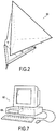
- some of the PR k reference points are equipped with a radar wave reflector 20, visible on the figure 2 , if their natural reflectivity of electromagnetic waves is not sufficient for these points to appear clearly on the radar images 12 taken by the satellite S.
- Each reflector 20 is aligned with the line of sight A of the satellite S , as is schematized on the figure 3 .
- This reflector 20 has the particularity of being orientable in order to be aligned with the axes of sight of satellites moving in different orbits. It has the shape of a trihedron whose tilt and azimuth can be adjusted.
- the satellite used is ENVISAT whose line of sight is at an angle of 23 ° with the vertical.
- step S110 is determined the actual variations ⁇ R X (PR j) the coordinates of reference points and the actual coordinates X R (PR j) of the reference points.
- the actual variations of the coordinates of the reference points and their real coordinates are determined by topographic measurements or by means of a GPS. Preferably, these measurements are carried out periodically, for example each day when a radar image 12 is taken.
- the topographic measurements can be carried out using one or more theodolites 22 aimed at targets arranged at the reference points PR j .
- reference points PR k For those of the reference points PR k of which the real coordinates X R (PR k ) and the actual variations ⁇ R X (PR k ) of coordinates are known during the study period, it is not necessary to carry out the periodic measurements mentioned above.
- Such reference points PR k will usually reference points equipped with reflectors 20 located in areas without soil movement.
- the reference points are used to correct the raw coordinates of the monitoring points.
- the real coordinates of these reference points and their estimated raw coordinates at the end of the interferometric process S010 are known.
- a correction is then calculated, for example a translation between the raw coordinates X B (PR j ) and the real coordinates X R (PR j ) of the reference points, which is then applied to the raw coordinates X B (PS i ) of all the monitoring points, whereby the corrected coordinates X C (PS i ) of the monitoring points are obtained, which makes it possible to appreciably improve the accuracy of their positions.
- step S130 for calculating the corrected variations ⁇ C X (PS i) of coordinates of monitoring points, made from raw variations ⁇ B X (PS i) the coordinates of the monitoring points, gross changes ⁇ B X (PR j) the coordinates of reference points and actual variations ⁇ R X (PR j) coordinates of the reference points.
- the date on which the oldest radar image 12 is taken is taken as the reference date. Coordinate variations are therefore relative to this date, but also to one of the reference points.
- a least squares error distribution algorithm is implemented by integrating the real coordinates of the reference points. This algorithm applies to coordinate variations between two radar images.
- the calculation step S130 for providing the corrected coordinate variations at the current time is applied between the date of the second radar image and the current time, the second radar image being that which was taken after the radar image whose date serves as a reference.
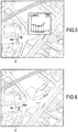
- a representation step S140 of the temporal variation of at least one of the corrected coordinates of one of the monitoring points PS 1 is carried out .
- the position of the monitoring point PS 1 and the corrected variation of its altitude are represented on a map C of a geographical information system. It is specified that this monitoring point PS 1 is positioned thanks to its corrected coordinates.
- the user by selecting the point PS 1, obtains a graph indicating the corrected change in altitude ⁇ z C (PS 1) from the point PS1 over time.
- a color code can also be used to allow the user to quickly visualize on the map C what the points of at the current time the most important variation of altitude.
- the monitoring method according to the invention is preferably in the form of a computer program comprising instructions in a standard programming language.
- this computer program is stored on a hard disk 60 of a computer 62, schematized on the figure 7 .
- This computer program can be loaded into a remotely accessible server by a remote computer.
- this monitoring method makes it possible to detect the eventual subsidence of a ground in which an underground structure, such as a tunnel, is made. Indeed, the deformations caused by the construction of a tunnel are most often nonlinear so that the algorithms currently used, performing a linear regression, do not allow to detect them.
Landscapes
- Engineering & Computer Science (AREA)
- Remote Sensing (AREA)
- Physics & Mathematics (AREA)
- Radar, Positioning & Navigation (AREA)
- Electromagnetism (AREA)
- General Physics & Mathematics (AREA)
- Computer Networks & Wireless Communication (AREA)
- Radar Systems Or Details Thereof (AREA)
- Position Fixing By Use Of Radio Waves (AREA)
- Image Processing (AREA)
- Geophysics And Detection Of Objects (AREA)
Claims (15)
- Verfahren zur Überwachung der Bewegungen eines Geländes, umfassend:- einen Schritt, bei dem die Rohänderungen (ΔBX(PSi)) der Koordinaten einer Vielzahl von auf dem Gelände befindlichen Überwachungspunkten (PSi) sowie die Rohänderungen (ΔBX(PRj)) der Koordinaten von wenigstens einem auf dem Gelände befindlichen Referenzpunkt (PRj) bereitgestellt werden,und dadurch gekennzeichnet, dass es umfasst:- einen Schritt zur Bestimmung (S110) der tatsächlichen Änderungen (ΔRX(PRj)) der Koordinaten des wenigstens einen Referenzpunktes,- einen Schritt zur Berechnung (S130) der korrigierten Änderungen (ΔCX(PSi)) der Koordinaten der Überwachungspunkte, welcher anhand der Rohänderungen der Koordinaten der Überwachungspunkte, der Rohänderungen der Koordinaten des Referenzpunktes und der tatsächlichen Änderungen der Koordinaten des Referenzpunktes durchgeführt wird.
- Verfahren zur Überwachung der Bewegungen eines Geländes nach Anspruch 1, dadurch gekennzeichnet, dass es ferner einen Schritt umfasst, bei dem die korrigierte zeitliche Änderung (ΔCz(PS1)) von wenigstens einer der Koordinaten von wenigstens einem der Überwachungspunkte (PS1) bestimmt wird.
- Überwachungsverfahren nach Anspruch 2, bei dem die korrigierte zeitliche Änderung von wenigstens einer der Koordinaten wenigstens eines der Überwachungspunkte die korrigierte Änderung der Höhe (ΔCz(PS1)) dieses Überwachungspunktes ist.
- Überwachungsverfahren nach Anspruch 2 oder 3, dadurch gekennzeichnet, dass es ferner einen Schritt zur Darstellung (S204) der zeitlichen Änderung umfasst.
- Überwachungsverfahren nach Anspruch 4, bei dem im Laufe des Darstellungsschrittes die Position eines jeden der Überwachungspunkte sowie die korrigierte Änderung (ΔCz(PSi)) der Höhe eines jeden der Überwachungspünkte auf einer geographischen Karte (C) oder Satelliten eines geographischen Informationssystems dargestellt werden.
- Überwachungsverfahren nach einem der Ansprüche 1 bis 5, bei dem der Schritt zur Berechnung (S130) der korrigierten Änderungen der Koordinaten der Überwachungspunkte (ΔCX(PSi)) mit Hilfe der Roh- und tatsächlichen Änderungen der Koordinaten der Referenzpunkte zwischen zwei aufeinanderfolgenden Zeitpunkten durchgeführt wird.
- Überwachungsverfahren nach einem der Ansprüche 1 bis 6, bei dem der Schritt zur Berechnung (S130) der korrigierten Änderungen der Koordinaten der Überwachungspunkte (ΔCX(PSi)) einen Fehlerverteilungsalgorithmus vom Typ kleinste Quadrate einsetzt.
- Überwachungsverfahren nach einem der Ansprüche 1 bis 7, dadurch gekennzeichnet, dass es ferner umfasst:- einen Schritt, bei dem die Rohkoordinaten XB(PSi) der Überwachungspunkte (PSi) und die Rohkoordinaten XB(PRj) des wenigstens einen Referenzpunktes (PRj) bereitgestellt werden,- einen Schritt zur Bestimmung der tatsächlichen Koordinaten XR(PRj) des Referenzpunktes (PRj),- einen Schritt zur Berechnung (S120) der korrigierten Koordinaten XC(PSi) der Überwachungspunkte, welcher anhand der Rohkoordinaten der Überwachungspunkte, der Rohkoordinaten des Referenzpunktes und der tatsächlichen Koordinaten des Referenzpunktes durchgeführt wird.
- Überwachungsverfahren nach Anspruch 8, bei dem die Rohänderungen der Koordinaten und/oder die Rohkoordinaten anhand einer interferometrischen Studie (S10), welche auf einem digitalen Geländemodell (14) und mehreren Radarbildern (12), die durch wenigstens eine Radarbildaufnahmevorrichtung (S) aufgenommen werden, basiert, bereitgestellt werden.
- Überwachungsverfahren nach Anspruch 9, bei dem wenigstens einer der Überwachungspunkte (PSi) des Geländes wenigstens einen Reflektor für elektromagnetische Wellen (20) umfasst, der dazu bestimmt ist, in Richtung der wenigstens einen Radarbildaufnahmevorrichtung (S) gerichtet zu werden.
- Überwachungsverfahren nach Anspruch 9 oder 10, bei dem wenigstens einer der Referenzpunkte (PRk) des Geländes wenigstens einen Reflektor für elektromagnetische Wellen (20) umfasst, der dazu bestimmt ist, in Richtung der wenigstens einen Radarbildaufnahmevorrichtung (S) gerichtet zu werden.
- Überwachungsverfahren nach einem der Ansprüche 1 bis 11, bei dem die tatsächlichen Koordinaten XR(PRj) der Referenzpunkte (PRj) durch GPS-Messungen oder mittels Topographie bestimmt werden.
- Computerprogramm, das Befehle für die Durchführung der Schritte des Überwachungsverfahrens nach einem der Ansprüche 1 bis 12, wenn das Programm durch einen Computer (62) ausgeführt wird, umfasst.
- Durch einen Computer (62) lesbarer Aufzeichnungsträger (60), auf dem das Computerprogramm des Anspruchs 13 gespeichert ist.
- Verwendung des Verfahrens nach einem der Ansprüche 1 bis 12, für die Überwachung von nicht linearen Verformungen des Geländes, welche insbesondere bei der Herstellung eines unterirdischen Bauwerks auftreten können.
Applications Claiming Priority (2)
| Application Number | Priority Date | Filing Date | Title |
|---|---|---|---|
| FR0955037A FR2948188B1 (fr) | 2009-07-20 | 2009-07-20 | Procede de surveillance des mouvements d'un terrain |
| PCT/FR2010/051425 WO2011010042A1 (fr) | 2009-07-20 | 2010-07-07 | Procédé de surveillance des mouvements d'un terrain |
Publications (2)
| Publication Number | Publication Date |
|---|---|
| EP2457059A1 EP2457059A1 (de) | 2012-05-30 |
| EP2457059B1 true EP2457059B1 (de) | 2017-01-04 |
Family
ID=41718720
Family Applications (1)
| Application Number | Title | Priority Date | Filing Date |
|---|---|---|---|
| EP10742209.9A Not-in-force EP2457059B1 (de) | 2009-07-20 | 2010-07-07 | Verfahren zur überwachung von bodenbewegungen |
Country Status (7)
| Country | Link |
|---|---|
| US (1) | US9046604B2 (de) |
| EP (1) | EP2457059B1 (de) |
| JP (1) | JP5614903B2 (de) |
| CA (1) | CA2767498C (de) |
| ES (1) | ES2620056T3 (de) |
| FR (1) | FR2948188B1 (de) |
| WO (1) | WO2011010042A1 (de) |
Families Citing this family (15)
| Publication number | Priority date | Publication date | Assignee | Title |
|---|---|---|---|---|
| FR2970818B1 (fr) * | 2011-01-25 | 2014-01-24 | Commissariat Energie Atomique | Reflecteur passif d'onde electromagnetique pour la mesure de deformation locale de structure a la surface de la terre |
| FR3014208B1 (fr) * | 2013-12-04 | 2016-02-12 | Onera (Off Nat Aerospatiale) | Systeme et procede pour mesurer la largeur d'une faille d'un site a surveiller |
| CN105549050B (zh) * | 2015-12-04 | 2017-11-28 | 合肥工业大学 | 一种基于模糊置信度滤波的北斗变形监测定位方法 |
| JP6696083B2 (ja) * | 2016-05-20 | 2020-05-20 | 国際航業株式会社 | 領域変位算出システム、領域変位算出方法、及び領域変位算出プログラム |
| EP3548924B1 (de) * | 2016-12-01 | 2024-03-13 | Thales Alenia Space Italia S.p.A. Con Unico Socio | Sar-basierte überwachung von unsichtbaren oder nicht immer sichtbaren oder teilweise sichtbaren zielen sowie zugehörige systeme und verfahren zur überwachung, erkennung von kritischen situationen und frühwarnung |
| JP7061435B2 (ja) * | 2017-05-31 | 2022-04-28 | 株式会社パスコ | 地盤変動観測装置及び地盤変動観測プログラム |
| CN110309525A (zh) * | 2019-03-22 | 2019-10-08 | 北京北科安地科技发展有限公司 | 一种边坡空间变形及破坏趋势计算方法 |
| JP7166971B2 (ja) * | 2019-03-26 | 2022-11-08 | 鹿島建設株式会社 | 地盤変動観測システム及び方法 |
| CN110146062B (zh) * | 2019-05-08 | 2022-04-01 | 西安长庆科技工程有限责任公司 | 一种基于图根点测量点云数据的坐标系转化方法 |
| JP6968307B2 (ja) * | 2019-10-31 | 2021-11-17 | 三菱電機株式会社 | 災害対応支援装置および災害対応支援方法 |
| JP7474439B2 (ja) * | 2020-08-04 | 2024-04-25 | 株式会社日豊 | 画像生成装置、画像生成方法、プログラム |
| US20250139793A1 (en) * | 2023-10-31 | 2025-05-01 | Agency For Defense Development | Method for changing target shooting cycle for reconnaissance of target and apparatus for the same |
| CN120403505A (zh) * | 2024-01-31 | 2025-08-01 | 中兴通讯股份有限公司 | 形变感知方法、装置、设备和介质 |
| KR102807778B1 (ko) | 2024-09-30 | 2025-05-16 | 한국건설기술연구원 | 위성 sar 데이터를 이용한 매립시설 유지관리 시스템 |
| KR102751028B1 (ko) | 2024-09-30 | 2025-01-09 | 한국건설기술연구원 | 매립시설 모니터링을 위한 위성 sar 신호 반사장치 |
Citations (1)
| Publication number | Priority date | Publication date | Assignee | Title |
|---|---|---|---|---|
| JPH09189762A (ja) * | 1996-01-08 | 1997-07-22 | Mitsubishi Electric Corp | レーダ装置を用いた地表変動観測方法並びにこの方法に用いる合成開口レーダ装置及びトランスポンダ |
Family Cites Families (12)
| Publication number | Priority date | Publication date | Assignee | Title |
|---|---|---|---|---|
| GB9524754D0 (en) * | 1995-12-04 | 1996-04-24 | Symmetricom Inc | Mobile position determination |
| JPH09230039A (ja) * | 1996-02-27 | 1997-09-05 | Mitsubishi Electric Corp | 干渉型合成開口レーダ装置及び合成開口レーダ装置を用いた地形高さ測定方法 |
| AU3797297A (en) * | 1996-07-11 | 1998-02-09 | Science Applications International Corporation | Terrain elevation measurement by interferometric synthetic aperture radar (ifsar) |
| US6396432B2 (en) * | 1998-06-16 | 2002-05-28 | C. Plath Gmbh, Nautisch-Elektronische Technik | Method and apparatus for the deception of satellite navigation |
| JP2001091649A (ja) * | 1999-09-20 | 2001-04-06 | Mitsubishi Electric Corp | 合成開口レーダ画像精密幾何補正用地上基準点装置 |
| CN1520522A (zh) * | 2001-03-14 | 2004-08-11 | 威顿技术公司 | 将位置信息与测量信息融合和进行滤波获得相对地球坐标精确定位的高质量图像的方法 |
| JP2002328021A (ja) * | 2001-04-27 | 2002-11-15 | Hayashi Katsuyoshi | ヘリコプター撮影による災害の被災量計測方法 |
| US6803878B2 (en) * | 2002-05-13 | 2004-10-12 | Honeywell International Inc. | Methods and apparatus for terrain correlation |
| US7233299B2 (en) * | 2002-10-24 | 2007-06-19 | Centre National De La Recherche Scientifique (C.N.R.S.) | Multiple-beam antenna with photonic bandgap material |
| JP2005024366A (ja) * | 2003-07-01 | 2005-01-27 | Hitachi Ltd | 火山溶岩流予測システム |
| JP4916777B2 (ja) * | 2006-06-05 | 2012-04-18 | 三菱電機株式会社 | 画像レーダ装置 |
| DE102010034318B4 (de) * | 2010-08-12 | 2012-02-23 | Jena-Optronik Gmbh | Verfahren und Vorrichtung zur korrigierten radiometrischen Messung von Objektpunkten auf Oberflächen von Himmelskörpern |
-
2009
- 2009-07-20 FR FR0955037A patent/FR2948188B1/fr active Active
-
2010
- 2010-07-07 CA CA2767498A patent/CA2767498C/en active Active
- 2010-07-07 ES ES10742209.9T patent/ES2620056T3/es active Active
- 2010-07-07 WO PCT/FR2010/051425 patent/WO2011010042A1/fr not_active Ceased
- 2010-07-07 EP EP10742209.9A patent/EP2457059B1/de not_active Not-in-force
- 2010-07-07 US US13/384,464 patent/US9046604B2/en not_active Expired - Fee Related
- 2010-07-07 JP JP2012521078A patent/JP5614903B2/ja not_active Expired - Fee Related
Patent Citations (1)
| Publication number | Priority date | Publication date | Assignee | Title |
|---|---|---|---|---|
| JPH09189762A (ja) * | 1996-01-08 | 1997-07-22 | Mitsubishi Electric Corp | レーダ装置を用いた地表変動観測方法並びにこの方法に用いる合成開口レーダ装置及びトランスポンダ |
Also Published As
| Publication number | Publication date |
|---|---|
| CA2767498A1 (en) | 2011-01-27 |
| JP2012533744A (ja) | 2012-12-27 |
| JP5614903B2 (ja) | 2014-10-29 |
| FR2948188B1 (fr) | 2011-09-09 |
| EP2457059A1 (de) | 2012-05-30 |
| ES2620056T3 (es) | 2017-06-27 |
| US9046604B2 (en) | 2015-06-02 |
| WO2011010042A1 (fr) | 2011-01-27 |
| CA2767498C (en) | 2018-09-04 |
| FR2948188A1 (fr) | 2011-01-21 |
| US20130011019A1 (en) | 2013-01-10 |
Similar Documents
| Publication | Publication Date | Title |
|---|---|---|
| EP2457059B1 (de) | Verfahren zur überwachung von bodenbewegungen | |
| Pacheco et al. | Retrieval of nearshore bathymetry from Landsat 8 images: A tool for coastal monitoring in shallow waters | |
| EP1828992B1 (de) | Verfahren zum verarbeiten von bildern unter verwendung automatischer georeferenzierung von bildern, die aus zwei in derselben fokalebene erfassten bildern abgeleitet werden | |
| CA2523717C (fr) | Procede et programme de reconstruction de plan de fracture | |
| WO2011073227A1 (fr) | Procede de geo-referencement d'une zone imagee | |
| EP2478334B1 (de) | Dreidimensionale ortung einer bestimmten landfläche mittels fusionierung von mit zwei satellitensensoren aufgenommenen bildern | |
| FR2860292A1 (fr) | Procede d'estimation de distance pour un mobile soumis a des contraintes dynamiques de parcours | |
| EP3359978B1 (de) | Verfahren zur verarbeitung eines sar-bildes und zugehöriges zielerfassungsverfahren | |
| EP3472557A1 (de) | Verfahren zur schätzung einer richtung der absoluten ausrichtung eines optronischen systems | |
| WO2005095888A1 (fr) | Procede d'estimation de distance curviligne pour mobile a manoeuvrabilite limitee | |
| Tran et al. | A geomorphology-based approach for digital elevation model fusion–case study in Danang city, Vietnam | |
| WO2013175022A1 (fr) | Systèmes et procédés de topographie et de reconstruction tridimensionnelle à partir d'un nuage de points et supports de stockage informatique pour ces systèmes et procédés | |
| EP4623270A2 (de) | Verfahren zur bestimmung, unter verwendung eines optronischen systems, von positionen und ausrichtungen in einer szene sowie zugehöriges optronisches system und fahrzeug | |
| FR2953316A1 (fr) | Procede d'obtention d'une base locale d'elevation de terrain a partir d'un moyen de detection embarque a bord d'un vehicule et dispositif pour la mise en oeuvre de ce procede | |
| CA3106745A1 (fr) | Procede d'observation d'une planete a l'aide de satellites d'observation en orbite autour de la planete | |
| EP2491424B1 (de) | Verfahren zur simultanen ortung und kartierung über elastische nichtlineare filterung | |
| FR2925735A1 (fr) | Procede de traitement d'une carte de differences determinee a partir de modeles numeriques de terrain | |
| Bourgine et al. | Generation of a ground-level DEM in a dense equatorial forest zone by merging airborne laser data and a top-of-canopy DEM | |
| FR2820214A1 (fr) | Procede de detection radar | |
| EP1229348A1 (de) | Verfahren zur Detektion und Charakterisierung von Hindernissen bei einem Radarsystem | |
| Wozencraft et al. | Use of SHOALS data to produce spectrally-derived depths in Kaneohe Bay, Hawaii | |
| Zhou | 100% automatic metrology with UAV photogrammetry and embedded GPS and its application in dike monitoring | |
| FR3165083A1 (fr) | Procédé de détermination de positions par un système optronique dans une scène, système optronique et véhicule associés | |
| Vos et al. | Satellite-derived shorelines for monitoring of sandy beaches: a benchmark study | |
| WO2023148455A1 (fr) | Dispositif, procédé et programme de relevé d'activité radiofréquence de satellites artificiels |
Legal Events
| Date | Code | Title | Description |
|---|---|---|---|
| PUAI | Public reference made under article 153(3) epc to a published international application that has entered the european phase |
Free format text: ORIGINAL CODE: 0009012 |
|
| 17P | Request for examination filed |
Effective date: 20120209 |
|
| AK | Designated contracting states |
Kind code of ref document: A1 Designated state(s): AL AT BE BG CH CY CZ DE DK EE ES FI FR GB GR HR HU IE IS IT LI LT LU LV MC MK MT NL NO PL PT RO SE SI SK SM TR |
|
| DAX | Request for extension of the european patent (deleted) | ||
| REG | Reference to a national code |
Ref country code: HK Ref legal event code: DE Ref document number: 1168418 Country of ref document: HK |
|
| GRAP | Despatch of communication of intention to grant a patent |
Free format text: ORIGINAL CODE: EPIDOSNIGR1 |
|
| INTG | Intention to grant announced |
Effective date: 20160805 |
|
| GRAS | Grant fee paid |
Free format text: ORIGINAL CODE: EPIDOSNIGR3 |
|
| GRAA | (expected) grant |
Free format text: ORIGINAL CODE: 0009210 |
|
| AK | Designated contracting states |
Kind code of ref document: B1 Designated state(s): AL AT BE BG CH CY CZ DE DK EE ES FI FR GB GR HR HU IE IS IT LI LT LU LV MC MK MT NL NO PL PT RO SE SI SK SM TR |
|
| REG | Reference to a national code |
Ref country code: GB Ref legal event code: FG4D Free format text: NOT ENGLISH |
|
| REG | Reference to a national code |
Ref country code: CH Ref legal event code: EP |
|
| REG | Reference to a national code |
Ref country code: AT Ref legal event code: REF Ref document number: 859683 Country of ref document: AT Kind code of ref document: T Effective date: 20170115 |
|
| REG | Reference to a national code |
Ref country code: IE Ref legal event code: FG4D Free format text: LANGUAGE OF EP DOCUMENT: FRENCH |
|
| REG | Reference to a national code |
Ref country code: DE Ref legal event code: R096 Ref document number: 602010039327 Country of ref document: DE |
|
| REG | Reference to a national code |
Ref country code: LT Ref legal event code: MG4D Ref country code: NL Ref legal event code: MP Effective date: 20170104 |
|
| REG | Reference to a national code |
Ref country code: AT Ref legal event code: MK05 Ref document number: 859683 Country of ref document: AT Kind code of ref document: T Effective date: 20170104 |
|
| REG | Reference to a national code |
Ref country code: FR Ref legal event code: PLFP Year of fee payment: 8 |
|
| REG | Reference to a national code |
Ref country code: ES Ref legal event code: FG2A Ref document number: 2620056 Country of ref document: ES Kind code of ref document: T3 Effective date: 20170627 |
|
| PG25 | Lapsed in a contracting state [announced via postgrant information from national office to epo] |
Ref country code: NL Free format text: LAPSE BECAUSE OF FAILURE TO SUBMIT A TRANSLATION OF THE DESCRIPTION OR TO PAY THE FEE WITHIN THE PRESCRIBED TIME-LIMIT Effective date: 20170104 |
|
| PG25 | Lapsed in a contracting state [announced via postgrant information from national office to epo] |
Ref country code: IS Free format text: LAPSE BECAUSE OF FAILURE TO SUBMIT A TRANSLATION OF THE DESCRIPTION OR TO PAY THE FEE WITHIN THE PRESCRIBED TIME-LIMIT Effective date: 20170504 Ref country code: FI Free format text: LAPSE BECAUSE OF FAILURE TO SUBMIT A TRANSLATION OF THE DESCRIPTION OR TO PAY THE FEE WITHIN THE PRESCRIBED TIME-LIMIT Effective date: 20170104 Ref country code: NO Free format text: LAPSE BECAUSE OF FAILURE TO SUBMIT A TRANSLATION OF THE DESCRIPTION OR TO PAY THE FEE WITHIN THE PRESCRIBED TIME-LIMIT Effective date: 20170404 Ref country code: GR Free format text: LAPSE BECAUSE OF FAILURE TO SUBMIT A TRANSLATION OF THE DESCRIPTION OR TO PAY THE FEE WITHIN THE PRESCRIBED TIME-LIMIT Effective date: 20170405 Ref country code: HR Free format text: LAPSE BECAUSE OF FAILURE TO SUBMIT A TRANSLATION OF THE DESCRIPTION OR TO PAY THE FEE WITHIN THE PRESCRIBED TIME-LIMIT Effective date: 20170104 Ref country code: LT Free format text: LAPSE BECAUSE OF FAILURE TO SUBMIT A TRANSLATION OF THE DESCRIPTION OR TO PAY THE FEE WITHIN THE PRESCRIBED TIME-LIMIT Effective date: 20170104 |
|
| PG25 | Lapsed in a contracting state [announced via postgrant information from national office to epo] |
Ref country code: PL Free format text: LAPSE BECAUSE OF FAILURE TO SUBMIT A TRANSLATION OF THE DESCRIPTION OR TO PAY THE FEE WITHIN THE PRESCRIBED TIME-LIMIT Effective date: 20170104 Ref country code: BG Free format text: LAPSE BECAUSE OF FAILURE TO SUBMIT A TRANSLATION OF THE DESCRIPTION OR TO PAY THE FEE WITHIN THE PRESCRIBED TIME-LIMIT Effective date: 20170404 Ref country code: AT Free format text: LAPSE BECAUSE OF FAILURE TO SUBMIT A TRANSLATION OF THE DESCRIPTION OR TO PAY THE FEE WITHIN THE PRESCRIBED TIME-LIMIT Effective date: 20170104 Ref country code: PT Free format text: LAPSE BECAUSE OF FAILURE TO SUBMIT A TRANSLATION OF THE DESCRIPTION OR TO PAY THE FEE WITHIN THE PRESCRIBED TIME-LIMIT Effective date: 20170504 Ref country code: SE Free format text: LAPSE BECAUSE OF FAILURE TO SUBMIT A TRANSLATION OF THE DESCRIPTION OR TO PAY THE FEE WITHIN THE PRESCRIBED TIME-LIMIT Effective date: 20170104 Ref country code: LV Free format text: LAPSE BECAUSE OF FAILURE TO SUBMIT A TRANSLATION OF THE DESCRIPTION OR TO PAY THE FEE WITHIN THE PRESCRIBED TIME-LIMIT Effective date: 20170104 |
|
| REG | Reference to a national code |
Ref country code: DE Ref legal event code: R097 Ref document number: 602010039327 Country of ref document: DE |
|
| PG25 | Lapsed in a contracting state [announced via postgrant information from national office to epo] |
Ref country code: RO Free format text: LAPSE BECAUSE OF FAILURE TO SUBMIT A TRANSLATION OF THE DESCRIPTION OR TO PAY THE FEE WITHIN THE PRESCRIBED TIME-LIMIT Effective date: 20170104 Ref country code: SK Free format text: LAPSE BECAUSE OF FAILURE TO SUBMIT A TRANSLATION OF THE DESCRIPTION OR TO PAY THE FEE WITHIN THE PRESCRIBED TIME-LIMIT Effective date: 20170104 Ref country code: EE Free format text: LAPSE BECAUSE OF FAILURE TO SUBMIT A TRANSLATION OF THE DESCRIPTION OR TO PAY THE FEE WITHIN THE PRESCRIBED TIME-LIMIT Effective date: 20170104 Ref country code: CZ Free format text: LAPSE BECAUSE OF FAILURE TO SUBMIT A TRANSLATION OF THE DESCRIPTION OR TO PAY THE FEE WITHIN THE PRESCRIBED TIME-LIMIT Effective date: 20170104 |
|
| PLBE | No opposition filed within time limit |
Free format text: ORIGINAL CODE: 0009261 |
|
| STAA | Information on the status of an ep patent application or granted ep patent |
Free format text: STATUS: NO OPPOSITION FILED WITHIN TIME LIMIT |
|
| PG25 | Lapsed in a contracting state [announced via postgrant information from national office to epo] |
Ref country code: SM Free format text: LAPSE BECAUSE OF FAILURE TO SUBMIT A TRANSLATION OF THE DESCRIPTION OR TO PAY THE FEE WITHIN THE PRESCRIBED TIME-LIMIT Effective date: 20170104 Ref country code: DK Free format text: LAPSE BECAUSE OF FAILURE TO SUBMIT A TRANSLATION OF THE DESCRIPTION OR TO PAY THE FEE WITHIN THE PRESCRIBED TIME-LIMIT Effective date: 20170104 |
|
| 26N | No opposition filed |
Effective date: 20171005 |
|
| REG | Reference to a national code |
Ref country code: DE Ref legal event code: R119 Ref document number: 602010039327 Country of ref document: DE |
|
| PG25 | Lapsed in a contracting state [announced via postgrant information from national office to epo] |
Ref country code: SI Free format text: LAPSE BECAUSE OF FAILURE TO SUBMIT A TRANSLATION OF THE DESCRIPTION OR TO PAY THE FEE WITHIN THE PRESCRIBED TIME-LIMIT Effective date: 20170104 |
|
| REG | Reference to a national code |
Ref country code: CH Ref legal event code: PL |
|
| REG | Reference to a national code |
Ref country code: IE Ref legal event code: MM4A |
|
| PG25 | Lapsed in a contracting state [announced via postgrant information from national office to epo] |
Ref country code: DE Free format text: LAPSE BECAUSE OF NON-PAYMENT OF DUE FEES Effective date: 20180201 Ref country code: LI Free format text: LAPSE BECAUSE OF NON-PAYMENT OF DUE FEES Effective date: 20170731 Ref country code: IE Free format text: LAPSE BECAUSE OF NON-PAYMENT OF DUE FEES Effective date: 20170707 Ref country code: CH Free format text: LAPSE BECAUSE OF NON-PAYMENT OF DUE FEES Effective date: 20170731 |
|
| REG | Reference to a national code |
Ref country code: BE Ref legal event code: MM Effective date: 20170731 |
|
| REG | Reference to a national code |
Ref country code: FR Ref legal event code: PLFP Year of fee payment: 9 |
|
| PG25 | Lapsed in a contracting state [announced via postgrant information from national office to epo] |
Ref country code: LU Free format text: LAPSE BECAUSE OF NON-PAYMENT OF DUE FEES Effective date: 20170707 |
|
| PG25 | Lapsed in a contracting state [announced via postgrant information from national office to epo] |
Ref country code: BE Free format text: LAPSE BECAUSE OF NON-PAYMENT OF DUE FEES Effective date: 20170731 |
|
| PG25 | Lapsed in a contracting state [announced via postgrant information from national office to epo] |
Ref country code: MT Free format text: LAPSE BECAUSE OF FAILURE TO SUBMIT A TRANSLATION OF THE DESCRIPTION OR TO PAY THE FEE WITHIN THE PRESCRIBED TIME-LIMIT Effective date: 20170104 |
|
| PG25 | Lapsed in a contracting state [announced via postgrant information from national office to epo] |
Ref country code: MC Free format text: LAPSE BECAUSE OF FAILURE TO SUBMIT A TRANSLATION OF THE DESCRIPTION OR TO PAY THE FEE WITHIN THE PRESCRIBED TIME-LIMIT Effective date: 20170104 Ref country code: HU Free format text: LAPSE BECAUSE OF FAILURE TO SUBMIT A TRANSLATION OF THE DESCRIPTION OR TO PAY THE FEE WITHIN THE PRESCRIBED TIME-LIMIT; INVALID AB INITIO Effective date: 20100707 |
|
| PG25 | Lapsed in a contracting state [announced via postgrant information from national office to epo] |
Ref country code: CY Free format text: LAPSE BECAUSE OF NON-PAYMENT OF DUE FEES Effective date: 20170104 |
|
| PG25 | Lapsed in a contracting state [announced via postgrant information from national office to epo] |
Ref country code: MK Free format text: LAPSE BECAUSE OF FAILURE TO SUBMIT A TRANSLATION OF THE DESCRIPTION OR TO PAY THE FEE WITHIN THE PRESCRIBED TIME-LIMIT Effective date: 20170104 |
|
| REG | Reference to a national code |
Ref country code: HK Ref legal event code: WD Ref document number: 1168418 Country of ref document: HK |
|
| PG25 | Lapsed in a contracting state [announced via postgrant information from national office to epo] |
Ref country code: TR Free format text: LAPSE BECAUSE OF FAILURE TO SUBMIT A TRANSLATION OF THE DESCRIPTION OR TO PAY THE FEE WITHIN THE PRESCRIBED TIME-LIMIT Effective date: 20170104 |
|
| PG25 | Lapsed in a contracting state [announced via postgrant information from national office to epo] |
Ref country code: AL Free format text: LAPSE BECAUSE OF FAILURE TO SUBMIT A TRANSLATION OF THE DESCRIPTION OR TO PAY THE FEE WITHIN THE PRESCRIBED TIME-LIMIT Effective date: 20170104 |
|
| PGFP | Annual fee paid to national office [announced via postgrant information from national office to epo] |
Ref country code: IT Payment date: 20220621 Year of fee payment: 13 Ref country code: GB Payment date: 20220621 Year of fee payment: 13 |
|
| PGFP | Annual fee paid to national office [announced via postgrant information from national office to epo] |
Ref country code: FR Payment date: 20220622 Year of fee payment: 13 |
|
| PGFP | Annual fee paid to national office [announced via postgrant information from national office to epo] |
Ref country code: ES Payment date: 20220801 Year of fee payment: 13 |
|
| P01 | Opt-out of the competence of the unified patent court (upc) registered |
Effective date: 20230528 |
|
| GBPC | Gb: european patent ceased through non-payment of renewal fee |
Effective date: 20230707 |
|
| PG25 | Lapsed in a contracting state [announced via postgrant information from national office to epo] |
Ref country code: GB Free format text: LAPSE BECAUSE OF NON-PAYMENT OF DUE FEES Effective date: 20230707 |
|
| PG25 | Lapsed in a contracting state [announced via postgrant information from national office to epo] |
Ref country code: FR Free format text: LAPSE BECAUSE OF NON-PAYMENT OF DUE FEES Effective date: 20230731 |
|
| PG25 | Lapsed in a contracting state [announced via postgrant information from national office to epo] |
Ref country code: IT Free format text: LAPSE BECAUSE OF NON-PAYMENT OF DUE FEES Effective date: 20230707 |
|
| REG | Reference to a national code |
Ref country code: ES Ref legal event code: FD2A Effective date: 20240827 |
|
| PG25 | Lapsed in a contracting state [announced via postgrant information from national office to epo] |
Ref country code: ES Free format text: LAPSE BECAUSE OF NON-PAYMENT OF DUE FEES Effective date: 20230708 |
|
| PG25 | Lapsed in a contracting state [announced via postgrant information from national office to epo] |
Ref country code: ES Free format text: LAPSE BECAUSE OF NON-PAYMENT OF DUE FEES Effective date: 20230708 |