EP2456986B1 - Vorrichtung zur steuerung eines luftzylinders - Google Patents
Vorrichtung zur steuerung eines luftzylinders Download PDFInfo
- Publication number
- EP2456986B1 EP2456986B1 EP10740381.8A EP10740381A EP2456986B1 EP 2456986 B1 EP2456986 B1 EP 2456986B1 EP 10740381 A EP10740381 A EP 10740381A EP 2456986 B1 EP2456986 B1 EP 2456986B1
- Authority
- EP
- European Patent Office
- Prior art keywords
- cylinder
- valve
- shaft
- control device
- pressure
- Prior art date
- Legal status (The legal status is an assumption and is not a legal conclusion. Google has not performed a legal analysis and makes no representation as to the accuracy of the status listed.)
- Active
Links
Images

Classifications
-
- C—CHEMISTRY; METALLURGY
- C25—ELECTROLYTIC OR ELECTROPHORETIC PROCESSES; APPARATUS THEREFOR
- C25C—PROCESSES FOR THE ELECTROLYTIC PRODUCTION, RECOVERY OR REFINING OF METALS; APPARATUS THEREFOR
- C25C3/00—Electrolytic production, recovery or refining of metals by electrolysis of melts
- C25C3/06—Electrolytic production, recovery or refining of metals by electrolysis of melts of aluminium
- C25C3/14—Devices for feeding or crust breaking
-
- F—MECHANICAL ENGINEERING; LIGHTING; HEATING; WEAPONS; BLASTING
- F15—FLUID-PRESSURE ACTUATORS; HYDRAULICS OR PNEUMATICS IN GENERAL
- F15B—SYSTEMS ACTING BY MEANS OF FLUIDS IN GENERAL; FLUID-PRESSURE ACTUATORS, e.g. SERVOMOTORS; DETAILS OF FLUID-PRESSURE SYSTEMS, NOT OTHERWISE PROVIDED FOR
- F15B15/00—Fluid-actuated devices for displacing a member from one position to another; Gearing associated therewith
- F15B15/20—Other details, e.g. assembly with regulating devices
- F15B15/26—Locking mechanisms
- F15B15/261—Locking mechanisms using positive interengagement, e.g. balls and grooves, for locking in the end positions
Definitions
- the present invention relates to a device for controlling a pneumatic cylinder.
- the context of the invention is that of pneumatic automatisms for the manufacturing industry and the process industries, in particular for aluminum smelters.
- the invention relates to a control device of a jack and more particularly to a control device of a crusher breaking cylinder.
- crush-breakers are used in steel and aluminum plants to break the surface crust formed on the surface of a molten metal, the break crusher cylinder is then used to form a hole in this crust allowing incorporate additives.
- the forces used can be significant, depending on the thickness and stiffness of the crust formed, it is the same during the ascent of the cylinder to "unhook" the slag and residues glued to the chisel, which requires the use of a large cylinder. If the formed crust is less thick or more friable the maximum breaking stress, or cleaning, will not be reached. As a result, the maximum pressurization will not be necessary in this case and a lower pressure will allow a reduction in consumption and thus a significant source energy saving.
- the document EP1255049 describes a control device of a jack.
- AU 27128/84 describes such a control device using a 5/2 distributor, a pressure reduction valve and a 3/2 valve controlled directly by a programmable industrial controller.
- a sensor can detect the end of the thrust and inform the controller.
- the present invention aims in particular to provide a control device of a cylinder for achieving energy savings, in particular by adapting the feed pressure to the effort just needed to break the crust and back up the cylinder by cleaning the chisel.
- a device for controlling a crusher air cylinder comprising a distributor and a valve, the cylinder being arranged vertically, above the surface of a molten metal, the cylinder rod equipped with a pointerolle being arranged facing the surface of the metal, is characterized in that it comprises a mechanical locking means of the cylinder rod in the upper position, allowing maintenance of the rod of the cylinder without the use of pneumatic energy.
- the mechanical locking means may comprise a bolt adapted to cooperate with a stop means provided on a finger integral with the rod of the jack.
- the stop means may be a groove or a shoulder.
- the bolt may include an orifice in which can penetrate the finger.
- the device also comprises a valve equipped with a mechanical sensor.
- the mechanical sensor may be a feeler.
- the probe can cooperate with an inclined surface provided on a trigger adapted to cooperate with the rod.
- the device is integrated in the cylinder body.
- the device can allow the adaptation of the supply pressure to the force just needed to break a resistance and reassemble the cylinder by breaking any friction forces of the application.
- the device may comprise means for detecting the low position of the rod by electrical contact between the chisel and the metal.
- the exhaust valve can include a flow limiter.
- the control device is schematically represented on the figure 1 .
- the cylinder 1 having a rod 2 integral with a piston 3.
- the cylinder comprises in the lower part an orifice 4 and in the upper part an orifice 5.
- the lower end of the rod 2 is secured to a chisel 6.
- the upper part of the piston 3 comprises a finger 7 provided with a groove 7a.
- the groove 7a is adapted to cooperate with the bolt 8a mu by the spring 15 of a locking device 8.
- the chisel is above the surface M of the molten metal.
- the surface M of the molten metal is electrically connected to the control part of a control device 10 via an automaton A.
- the control device also comprises a 5/2 type distributor 9.
- the pressure inlet of the distributor 9 feeds a valve 3/2 11, while the orifice 5 of the cylinder 1 is connected to the exhaust of the distributor 9.
- the pressure inlet feeds the orifice 5, the orifice 4 being exhausted.
- the valve 11 is shown in a position where the slide is in a position 11c allowing the outlet of the lower chamber of the cylinder 1 through the orifice 4
- the distributor 9, the locking device 8 and the valve 11 are controlled by the control device 10.
- the cylinder is then at rest in the high position.
- the steering device is shown Fig. 1 with its drawer in a position 10b where the pressure supply is blocked while the pipe to the locking device 8, the distributor 9 and the valve 11 is exhausted. In another position 10a, the pipe towards the locking device 8, the distributor 9 and the valve 11 is connected to the pressure inlet.
- valve 11 can also be controlled mechanically via a probe 11a.
- the control device 10 makes it possible to cause the slide of the valve 11 to be lowered, but the feeler 11a is able, in contact with the piston 3, to control the raising of the slide of the valve 11.
- a second step when the chisel 6 comes into contact with the molten aluminum M, the jack in contact with the aluminum behaves as an electrical contact.
- the cylinder 1 is made in such a way that there is electrical continuity between the chisel 6 and the rear bottom of the cylinder.
- a metal bearing not shown, is used and when the chisel 6 comes into contact with the aluminum M, an electrical signal can feed a controller A and cause the shutdown of the control device 10 and its passage in position 10b .
- the orifice 4 is then connected to the supply of the distributor 9 through the valve 11.
- the rod 2 and the chisel 6 then begin their ascent.
- the piston 3 causes the return of the probe 11a. Arriving at the top, during the rise, the piston 3 and the rod 7 slightly exceed the engagement of the bolt 8a to ensure the complete tilting of the valve 11 in the position 11 c. This change of state causes the atmosphere of the lower chamber of the breaker cylinder to be vented.
- control device can be integrated with the cylinder 1.
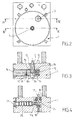
- Figures 2 to 5 illustrate an embodiment of the bottom of the cylinder 1, modified to accommodate the control device according to the invention.
- Fig. 3 can see the finger 7, slidably mounted in a housing 13 provided in the bottom of the cylinder 1, which has a thread in its upper part for fixing on the piston 3.
- the lower part of the finger 7 has a shoulder 7b which serves stop means.
- the bolt 8a is made in the form of a slide guided in translation, orthogonal to the direction of movement of the finger 7, in a second housing 14 provided in the bottom of the cylinder 1 and made in the form of a blind cylindrical orifice.
- a spring 15 is interposed between the wall of the housing 14 and the bolt 8a while the housing 14 is closed by a plug 16.
- the bolt 8a comprises an orifice 8b in which can penetrate the finger 7.
- the orifice 8b has an inner lip 8c adapted to cooperate with the shoulder 7b.
- valve 11 integrated in the bottom of the jack 1 can be seen.
- the slide 20 of the valve 11 and the probe 11a are slidably mounted in a recess provided in the bottom of the jack 1 and closed by a plug 21.
- the probe n ' is not here in direct contact with the piston 3.
- a trigger 12 is installed in a housing provided in the bottom of the cylinder 1 and closed by a plug 19 having an orifice allowing the passage of one end of the trigger 12.
- a spring 18 exerts a force on the trigger 12 tending to maintain the trigger 12 against the plug 19 so that the end of the trigger 12 slightly exceeds the plug 19.
- the displacement of the trigger is a translational movement along an axis parallel to the direction of movement of the piston 3.
- the trigger 12 comprises an inclined surface 12a adapted to cooperate with the rounded end of the probe 11a. In this way, when the piston 3 comes into contact with the end of the trigger 12 and causes the trigger 12 to fall back into its housing, the surface 12a exerts a force on the probe 11a which causes the displacement of the valve spool 20 11.
- This mechanism thus allows the detection of the arrival of the piston 3 in the high position and thus causes the change of state of the valve 11 and the depressurization of the inlet 4 of the piston 1.
- the exhaust cylinder 1 is oversized.
- the pressure inlet has a low flow rate so as to avoid a too high pressure rise in the drive chambers. In this way, full pressure can be reached in about 7 seconds. The maximum pressure is about 7 bars. Nevertheless, during the ascent and following the degree of soiling of the chisel, this pressure is often not necessary. Indeed, 1 bar is sufficient for the lift of the cylinder given the weight hitched to the rod. During the descent phase, the rise in pressure takes place only if the resistance of the crust requires it.
Landscapes
- Engineering & Computer Science (AREA)
- Chemical & Material Sciences (AREA)
- Chemical Kinetics & Catalysis (AREA)
- Mechanical Engineering (AREA)
- General Engineering & Computer Science (AREA)
- Fluid Mechanics (AREA)
- Physics & Mathematics (AREA)
- Electrochemistry (AREA)
- Materials Engineering (AREA)
- Metallurgy (AREA)
- Organic Chemistry (AREA)
- Percussive Tools And Related Accessories (AREA)
- Actuator (AREA)
- Preliminary Treatment Of Fibers (AREA)
Claims (11)
- Steuervorrichtung für einen Krustenbrecher-Pneumatikzylinder (1), umfassend einen Verteiler (9) und ein Ventil (11), wobei der Zylinder (1) vertikal oberhalb einer Fläche (M) eines geschmolzenen Metalls angeordnet ist und die Kolbenstange (2) des Zylinders (1) mit einem Meißel (6) versehen ist, der so angeordnet ist, dass er der Metalloberfläche (M) zugewandt ist, dadurch gekennzeichnet, dass sie eine mechanische Verriegelungseinrichtung (8) der Kolbenstange (2, 3, 7) des Zylinders (1) aufweist, die ein Halten der Kolbenstange des Zylinders in einer oberen Stellung ohne Verwenden von pneumatischer Energie ermöglicht.
- Vorrichtung nach Anspruch 1, dadurch gekennzeichnet, dass die mechanische Verriegelungseinrichtung (8) einen Bolzen (8a) umfasst, der dazu ausgelegt ist, mit einer Arretiereinrichtung, die an einem fest mit der Kolbenstange (2) des Zylinders (1) verbundenen Finger (7) vorgesehen ist, zusammenzuwirken.
- Vorrichtung nach Anspruch 2, dadurch gekennzeichnet, dass die Arretiereinrichtung eine Rille (7a) oder eine Schulter ist.
- Vorrichtung nach Anspruch 2 oder 3, dadurch gekennzeichnet, dass der Bolzen (8a) eine Öffnung (8b) umfasst, in die der Finger (7) eingreifen kann.
- Vorrichtung nach einem der vorhergehenden Ansprüche 1 bis 4, dadurch gekennzeichnet, dass sie ferner ein Ventil (11) umfasst, das mit einem mechanischen Sensor versehen ist.
- Vorrichtung nach Anspruch 5, dadurch gekennzeichnet, dass der mechanische Sensor ein Fühler (11a) ist.
- Vorrichtung nach Anspruch 6, dadurch gekennzeichnet, dass der Fühler (11a) mit einer geneigten Oberfläche (12a) zusammenwirkt, die an einem Auslöser (12) vorgesehen ist, der geeignet ist mit dem Kolbenstange (2) zusammenzuwirken.
- Vorrichtung nach einem der vorhergehenden Ansprüche, dadurch gekennzeichnet, dass die Vorrichtung in den Körper des Zylinders (1) integriert ist.
- Vorrichtung nach einem der vorhergehenden Ansprüche, dadurch gekennzeichnet, dass die Vorrichtung eine Druckanpassung bis zu einer Kraft ermöglicht, die gerade dazu notwendig ist einen Widerstand zu brechen und den Zylinder (1) beim Brechen etwaiger Reibungskräfte während der Anwendung hochzuziehen.
- Vorrichtung nach einem der vorhergehenden Ansprüche, dadurch gekennzeichnet, dass sie eine Einrichtung zum Erfassen der unteren Stellung der Kolbenstange (2) durch einen elektrischen Kontakt zwischen dem Meißel (6) und dem Metall (M) aufweist.
- Vorrichtung nach einem der vorhergehenden Ansprüche, dadurch gekennzeichnet, dass das Ablassventil des Ventils (11) einen Volumenstrombegrenzer aufweist.
Applications Claiming Priority (2)
| Application Number | Priority Date | Filing Date | Title |
|---|---|---|---|
| FR0903581A FR2948426B1 (fr) | 2009-07-21 | 2009-07-21 | Dispositif de commande d'un verin pneumatique |
| PCT/IB2010/053276 WO2011010274A1 (fr) | 2009-07-21 | 2010-07-19 | Dispositif de commande d'un vérin pneumatique |
Publications (3)
| Publication Number | Publication Date |
|---|---|
| EP2456986A1 EP2456986A1 (de) | 2012-05-30 |
| EP2456986B1 true EP2456986B1 (de) | 2014-02-26 |
| EP2456986B2 EP2456986B2 (de) | 2018-08-29 |
Family
ID=41693127
Family Applications (1)
| Application Number | Title | Priority Date | Filing Date |
|---|---|---|---|
| EP10740381.8A Active EP2456986B2 (de) | 2009-07-21 | 2010-07-19 | Vorrichtung zur steuerung eines luftzylinders |
Country Status (8)
| Country | Link |
|---|---|
| EP (1) | EP2456986B2 (de) |
| CN (2) | CN102472302A (de) |
| AU (1) | AU2010274613B2 (de) |
| CA (1) | CA2767588C (de) |
| FR (1) | FR2948426B1 (de) |
| IN (1) | IN2012DN00556A (de) |
| WO (1) | WO2011010274A1 (de) |
| ZA (1) | ZA201200414B (de) |
Cited By (1)
| Publication number | Priority date | Publication date | Assignee | Title |
|---|---|---|---|---|
| CN104674302A (zh) * | 2015-03-19 | 2015-06-03 | 河南理工大学 | 一种高强度电解铝打壳机导引板 |
Families Citing this family (28)
| Publication number | Priority date | Publication date | Assignee | Title |
|---|---|---|---|---|
| US8905063B2 (en) | 2011-12-15 | 2014-12-09 | Honeywell International Inc. | Gas valve with fuel rate monitor |
| US9835265B2 (en) | 2011-12-15 | 2017-12-05 | Honeywell International Inc. | Valve with actuator diagnostics |
| US9846440B2 (en) | 2011-12-15 | 2017-12-19 | Honeywell International Inc. | Valve controller configured to estimate fuel comsumption |
| US9995486B2 (en) | 2011-12-15 | 2018-06-12 | Honeywell International Inc. | Gas valve with high/low gas pressure detection |
| US8947242B2 (en) | 2011-12-15 | 2015-02-03 | Honeywell International Inc. | Gas valve with valve leakage test |
| US8839815B2 (en) | 2011-12-15 | 2014-09-23 | Honeywell International Inc. | Gas valve with electronic cycle counter |
| US9074770B2 (en) | 2011-12-15 | 2015-07-07 | Honeywell International Inc. | Gas valve with electronic valve proving system |
| US9557059B2 (en) | 2011-12-15 | 2017-01-31 | Honeywell International Inc | Gas valve with communication link |
| US8899264B2 (en) | 2011-12-15 | 2014-12-02 | Honeywell International Inc. | Gas valve with electronic proof of closure system |
| US9851103B2 (en) | 2011-12-15 | 2017-12-26 | Honeywell International Inc. | Gas valve with overpressure diagnostics |
| CN102618889A (zh) * | 2012-04-26 | 2012-08-01 | 山西兆丰铝业有限责任公司 | 铝电解槽打壳锤头 |
| US9234661B2 (en) | 2012-09-15 | 2016-01-12 | Honeywell International Inc. | Burner control system |
| US10422531B2 (en) | 2012-09-15 | 2019-09-24 | Honeywell International Inc. | System and approach for controlling a combustion chamber |
| CN102828202B (zh) * | 2012-09-17 | 2015-04-22 | 北京爱社时代科技发展有限公司 | 一种新型的智能打壳缸 |
| EP2868970B1 (de) | 2013-10-29 | 2020-04-22 | Honeywell Technologies Sarl | Regelungsvorrichtung |
| US10024439B2 (en) | 2013-12-16 | 2018-07-17 | Honeywell International Inc. | Valve over-travel mechanism |
| CN103938226B (zh) * | 2014-04-18 | 2016-08-17 | 东北大学 | 一种多功能电解铝打壳气动控制系统 |
| CN104005057B (zh) * | 2014-04-29 | 2016-05-18 | 中国铝业股份有限公司 | 一种多功能联合机组打壳机自动锁定装置 |
| US9841122B2 (en) | 2014-09-09 | 2017-12-12 | Honeywell International Inc. | Gas valve with electronic valve proving system |
| US9645584B2 (en) | 2014-09-17 | 2017-05-09 | Honeywell International Inc. | Gas valve with electronic health monitoring |
| US10503181B2 (en) | 2016-01-13 | 2019-12-10 | Honeywell International Inc. | Pressure regulator |
| CN105736503B (zh) * | 2016-04-22 | 2017-07-07 | 济南弋泽展特机械有限公司 | 一种气路阀件 |
| US10564062B2 (en) | 2016-10-19 | 2020-02-18 | Honeywell International Inc. | Human-machine interface for gas valve |
| US11073281B2 (en) | 2017-12-29 | 2021-07-27 | Honeywell International Inc. | Closed-loop programming and control of a combustion appliance |
| US10697815B2 (en) | 2018-06-09 | 2020-06-30 | Honeywell International Inc. | System and methods for mitigating condensation in a sensor module |
| DE102019104283A1 (de) | 2019-02-20 | 2020-08-20 | Saurer Technologies GmbH & Co. KG | Steuereinheit zur pneumatischen Ansteuerung eines aktiven Spulengatters |
| CN112498751B (zh) * | 2020-12-15 | 2024-06-25 | 航天科工火箭技术有限公司 | 一种连接解锁装置 |
| CN112760680B (zh) * | 2020-12-19 | 2024-02-02 | 内蒙古锦溪科技股份有限公司 | 一种可变行程打壳气缸 |
Family Cites Families (19)
| Publication number | Priority date | Publication date | Assignee | Title |
|---|---|---|---|---|
| US3359862A (en) † | 1966-02-25 | 1967-12-26 | Mcdowell Wellman Eng Co | Piston locking means |
| SE8000081L (sv) † | 1980-01-04 | 1981-07-05 | Mecman Ab | Lasmekanism for tryckmediecylindrar |
| EP0124480B1 (de) | 1983-05-03 | 1987-10-28 | Schweizerische Aluminium Ag | Elektropneumatisches Antriebssystem für Krustenbrechvorrichtungen und Verfahren zu deren Betrieb |
| US4700612A (en) * | 1983-05-03 | 1987-10-20 | Swiss Aluminium Ltd. | Electropneumatic drive system for crust breaking devices and process for operating the same |
| US4524676A (en) * | 1984-01-19 | 1985-06-25 | American Standard Inc. | Hydraulic cylinder locking device |
| DE3809325A1 (de) * | 1988-03-19 | 1989-10-05 | Bosch Gmbh Robert | Tuerbetaetigungsvorrichtung |
| US5365828A (en) * | 1992-06-27 | 1994-11-22 | Deutsche Aerospace Ag | Pneumatic linear drive comprising a locking mechanism for end positions |
| WO1996002764A1 (en) * | 1994-07-15 | 1996-02-01 | Terry Fluid Controls Pty. Ltd. | Actuator |
| US6436270B1 (en) * | 1999-07-19 | 2002-08-20 | Ab Rexroth Mecman | Method and device for controlling the movement of a feeding and breaking chisel in an aluminum production cell |
| JP3930665B2 (ja) * | 1999-07-23 | 2007-06-13 | 株式会社コガネイ | 流体圧シリンダ |
| JP3559213B2 (ja) * | 2000-03-03 | 2004-08-25 | 株式会社半導体先端テクノロジーズ | ロードポート及びそれを用いた生産方式 |
| US6649035B2 (en) * | 2001-05-04 | 2003-11-18 | Ross Operating Valve Company | Low energy and non-heat transferring crust breaking system |
| CN2509362Y (zh) * | 2001-10-12 | 2002-09-04 | 济南华能气动元器件公司 | 带活塞杆自锁装置的气缸 |
| CN2584616Y (zh) * | 2002-12-16 | 2003-11-05 | 阜新市液压气动配套厂 | 耐高温、自润滑、机械防下落打壳气缸 |
| CN2739394Y (zh) * | 2004-06-30 | 2005-11-09 | 贵阳铝镁设计研究院 | 气缸自锁装置 |
| GB0520497D0 (en) † | 2005-10-08 | 2005-11-16 | Imi Norgren Ltd | Actuator assembly |
| US7281464B2 (en) † | 2006-02-16 | 2007-10-16 | Ross Operating Valve Company | Inlet monitor and latch for a crust breaking system |
| CN101384825B (zh) * | 2006-02-21 | 2011-11-16 | 费斯托股份有限两合公司 | 气动驱动系统 |
| CN101605927B (zh) * | 2007-02-07 | 2012-04-04 | 费斯托股份有限两合公司 | 用以捅破在金属熔液池上所形成的硬皮的硬皮破碎机 |
-
2009
- 2009-07-21 FR FR0903581A patent/FR2948426B1/fr active Active
-
2010
- 2010-07-19 CN CN2010800328340A patent/CN102472302A/zh active Pending
- 2010-07-19 EP EP10740381.8A patent/EP2456986B2/de active Active
- 2010-07-19 IN IN556DEN2012 patent/IN2012DN00556A/en unknown
- 2010-07-19 CN CN201611078753.XA patent/CN106835198B/zh active Active
- 2010-07-19 CA CA2767588A patent/CA2767588C/fr active Active
- 2010-07-19 WO PCT/IB2010/053276 patent/WO2011010274A1/fr not_active Ceased
- 2010-07-19 AU AU2010274613A patent/AU2010274613B2/en active Active
-
2012
- 2012-01-18 ZA ZA2012/00414A patent/ZA201200414B/en unknown
Cited By (1)
| Publication number | Priority date | Publication date | Assignee | Title |
|---|---|---|---|---|
| CN104674302A (zh) * | 2015-03-19 | 2015-06-03 | 河南理工大学 | 一种高强度电解铝打壳机导引板 |
Also Published As
| Publication number | Publication date |
|---|---|
| CN106835198B (zh) | 2021-01-15 |
| FR2948426A1 (fr) | 2011-01-28 |
| CN106835198A (zh) | 2017-06-13 |
| WO2011010274A1 (fr) | 2011-01-27 |
| FR2948426B1 (fr) | 2011-09-02 |
| IN2012DN00556A (de) | 2015-06-12 |
| EP2456986A1 (de) | 2012-05-30 |
| ZA201200414B (en) | 2012-09-26 |
| AU2010274613A1 (en) | 2012-02-02 |
| AU2010274613B2 (en) | 2016-03-24 |
| CN102472302A (zh) | 2012-05-23 |
| EP2456986B2 (de) | 2018-08-29 |
| CA2767588C (fr) | 2017-12-05 |
| CA2767588A1 (fr) | 2011-01-27 |
Similar Documents
| Publication | Publication Date | Title |
|---|---|---|
| EP2456986B1 (de) | Vorrichtung zur steuerung eines luftzylinders | |
| EP0122851B1 (de) | Sicherheitsberstscheibe mit Messer zum Begrenzen des Drucks eines Fluidums | |
| EP2255065B1 (de) | Verfahren zur installation eines unterwasser-steigrohrs | |
| FR2966392A1 (fr) | Dispositif de verrouillage et de deverrouillage d'un bac de batterie de vehicule automobile electrique | |
| FR2912323A1 (fr) | Dispositif de positionnement automatique assiste d'une enceinte de chauffage contre un ballon de distillation. | |
| EP2097560A2 (de) | Vorrichtung zur steuerung des wegs eines krustenbrechers eines beschickungssystems einer elektrolysezelle zur herstellung von aluminium | |
| EP1905724B1 (de) | Hubvorrichtung | |
| FR2793450A1 (fr) | Reservoir a carburant a poche souple | |
| EP1588939A1 (de) | Fahrwerk mit einem Stossdämpfer mit drei Kammern | |
| EP2585624B1 (de) | Vorrichtung zur entfernung von kurzschliessungsblockierungen bei der inbetriebnahme einer elektrolysezelle zur herstellung von aluminium | |
| EP2485260A3 (de) | Montage- und hermetisches Schließverfahren eines Einkapselungsgehäuses | |
| EP2383456B1 (de) | Einfach wirkender Hydraulikzylinder | |
| FR2530779A1 (fr) | Liaison de securite reliant un recipient contenant un gaz sous pression a un systeme d'evacuation | |
| EP3942194B1 (de) | Einstellbarer dämpfer für ein fahrrad | |
| FR2978226A1 (fr) | Event de surpression pour un reservoir contenant une phase gazeuse et reservoir equipe dudit event | |
| FR2524173A1 (fr) | Systeme de remplissage d'un reservoir a liquide | |
| FR2928906A3 (fr) | Anneau de levage de bloc moteur,ensemble comportant un bloc-moteur et un tel anneau de levage,et vehicule automobile correspondant | |
| FR2542346A1 (fr) | Robinet pour reservoir de chasse d'eau | |
| FR2938272A1 (fr) | Dispositif de securite garantissant la fermeture d'un tambour de machine a laver | |
| FR2778397A1 (fr) | Dispositif de remplissage pour reservoir de gaz de petrole liquefie | |
| EP2872784B1 (de) | Vorrichtung zur steuerung der bewegung eines hydraulikzylinders, insbesondere für hydraulikmaschinen | |
| FR2528146A1 (fr) | Valve magnetique pilotee a systeme d'obturation perfectionne | |
| EP1312844A1 (de) | Ventil für Gasbehälter oder Gasleitung mit einem Hebel | |
| EP2236680A1 (de) | Zweimengenspülsystem mit Magnetventil | |
| EP1007247A1 (de) | Verfahren und vorrichtung zum stranggiessen von metallen mit kokillen-aufsatz |
Legal Events
| Date | Code | Title | Description |
|---|---|---|---|
| PUAI | Public reference made under article 153(3) epc to a published international application that has entered the european phase |
Free format text: ORIGINAL CODE: 0009012 |
|
| 17P | Request for examination filed |
Effective date: 20120119 |
|
| AK | Designated contracting states |
Kind code of ref document: A1 Designated state(s): AL AT BE BG CH CY CZ DE DK EE ES FI FR GB GR HR HU IE IS IT LI LT LU LV MC MK MT NL NO PL PT RO SE SI SK SM TR |
|
| DAX | Request for extension of the european patent (deleted) | ||
| GRAP | Despatch of communication of intention to grant a patent |
Free format text: ORIGINAL CODE: EPIDOSNIGR1 |
|
| INTG | Intention to grant announced |
Effective date: 20130705 |
|
| GRAP | Despatch of communication of intention to grant a patent |
Free format text: ORIGINAL CODE: EPIDOSNIGR1 |
|
| INTG | Intention to grant announced |
Effective date: 20131030 |
|
| GRAS | Grant fee paid |
Free format text: ORIGINAL CODE: EPIDOSNIGR3 |
|
| GRAA | (expected) grant |
Free format text: ORIGINAL CODE: 0009210 |
|
| AK | Designated contracting states |
Kind code of ref document: B1 Designated state(s): AL AT BE BG CH CY CZ DE DK EE ES FI FR GB GR HR HU IE IS IT LI LT LU LV MC MK MT NL NO PL PT RO SE SI SK SM TR |
|
| REG | Reference to a national code |
Ref country code: GB Ref legal event code: FG4D Free format text: NOT ENGLISH |
|
| REG | Reference to a national code |
Ref country code: CH Ref legal event code: EP |
|
| REG | Reference to a national code |
Ref country code: AT Ref legal event code: REF Ref document number: 653788 Country of ref document: AT Kind code of ref document: T Effective date: 20140315 |
|
| REG | Reference to a national code |
Ref country code: IE Ref legal event code: FG4D Free format text: LANGUAGE OF EP DOCUMENT: FRENCH |
|
| REG | Reference to a national code |
Ref country code: DE Ref legal event code: R096 Ref document number: 602010013771 Country of ref document: DE Effective date: 20140410 |
|
| REG | Reference to a national code |
Ref country code: NL Ref legal event code: VDEP Effective date: 20140226 |
|
| REG | Reference to a national code |
Ref country code: AT Ref legal event code: MK05 Ref document number: 653788 Country of ref document: AT Kind code of ref document: T Effective date: 20140226 |
|
| REG | Reference to a national code |
Ref country code: LT Ref legal event code: MG4D |
|
| PG25 | Lapsed in a contracting state [announced via postgrant information from national office to epo] |
Ref country code: NO Free format text: LAPSE BECAUSE OF FAILURE TO SUBMIT A TRANSLATION OF THE DESCRIPTION OR TO PAY THE FEE WITHIN THE PRESCRIBED TIME-LIMIT Effective date: 20140526 Ref country code: LT Free format text: LAPSE BECAUSE OF FAILURE TO SUBMIT A TRANSLATION OF THE DESCRIPTION OR TO PAY THE FEE WITHIN THE PRESCRIBED TIME-LIMIT Effective date: 20140226 Ref country code: IS Free format text: LAPSE BECAUSE OF FAILURE TO SUBMIT A TRANSLATION OF THE DESCRIPTION OR TO PAY THE FEE WITHIN THE PRESCRIBED TIME-LIMIT Effective date: 20140626 |
|
| PG25 | Lapsed in a contracting state [announced via postgrant information from national office to epo] |
Ref country code: CY Free format text: LAPSE BECAUSE OF FAILURE TO SUBMIT A TRANSLATION OF THE DESCRIPTION OR TO PAY THE FEE WITHIN THE PRESCRIBED TIME-LIMIT Effective date: 20140226 Ref country code: AT Free format text: LAPSE BECAUSE OF FAILURE TO SUBMIT A TRANSLATION OF THE DESCRIPTION OR TO PAY THE FEE WITHIN THE PRESCRIBED TIME-LIMIT Effective date: 20140226 Ref country code: SE Free format text: LAPSE BECAUSE OF FAILURE TO SUBMIT A TRANSLATION OF THE DESCRIPTION OR TO PAY THE FEE WITHIN THE PRESCRIBED TIME-LIMIT Effective date: 20140226 Ref country code: PT Free format text: LAPSE BECAUSE OF FAILURE TO SUBMIT A TRANSLATION OF THE DESCRIPTION OR TO PAY THE FEE WITHIN THE PRESCRIBED TIME-LIMIT Effective date: 20140626 Ref country code: FI Free format text: LAPSE BECAUSE OF FAILURE TO SUBMIT A TRANSLATION OF THE DESCRIPTION OR TO PAY THE FEE WITHIN THE PRESCRIBED TIME-LIMIT Effective date: 20140226 Ref country code: NL Free format text: LAPSE BECAUSE OF FAILURE TO SUBMIT A TRANSLATION OF THE DESCRIPTION OR TO PAY THE FEE WITHIN THE PRESCRIBED TIME-LIMIT Effective date: 20140226 |
|
| PG25 | Lapsed in a contracting state [announced via postgrant information from national office to epo] |
Ref country code: HR Free format text: LAPSE BECAUSE OF FAILURE TO SUBMIT A TRANSLATION OF THE DESCRIPTION OR TO PAY THE FEE WITHIN THE PRESCRIBED TIME-LIMIT Effective date: 20140226 Ref country code: LV Free format text: LAPSE BECAUSE OF FAILURE TO SUBMIT A TRANSLATION OF THE DESCRIPTION OR TO PAY THE FEE WITHIN THE PRESCRIBED TIME-LIMIT Effective date: 20140226 |
|
| PG25 | Lapsed in a contracting state [announced via postgrant information from national office to epo] |
Ref country code: EE Free format text: LAPSE BECAUSE OF FAILURE TO SUBMIT A TRANSLATION OF THE DESCRIPTION OR TO PAY THE FEE WITHIN THE PRESCRIBED TIME-LIMIT Effective date: 20140226 Ref country code: CZ Free format text: LAPSE BECAUSE OF FAILURE TO SUBMIT A TRANSLATION OF THE DESCRIPTION OR TO PAY THE FEE WITHIN THE PRESCRIBED TIME-LIMIT Effective date: 20140226 Ref country code: DK Free format text: LAPSE BECAUSE OF FAILURE TO SUBMIT A TRANSLATION OF THE DESCRIPTION OR TO PAY THE FEE WITHIN THE PRESCRIBED TIME-LIMIT Effective date: 20140226 Ref country code: RO Free format text: LAPSE BECAUSE OF FAILURE TO SUBMIT A TRANSLATION OF THE DESCRIPTION OR TO PAY THE FEE WITHIN THE PRESCRIBED TIME-LIMIT Effective date: 20140226 |
|
| REG | Reference to a national code |
Ref country code: DE Ref legal event code: R026 Ref document number: 602010013771 Country of ref document: DE |
|
| PG25 | Lapsed in a contracting state [announced via postgrant information from national office to epo] |
Ref country code: ES Free format text: LAPSE BECAUSE OF FAILURE TO SUBMIT A TRANSLATION OF THE DESCRIPTION OR TO PAY THE FEE WITHIN THE PRESCRIBED TIME-LIMIT Effective date: 20140226 Ref country code: SK Free format text: LAPSE BECAUSE OF FAILURE TO SUBMIT A TRANSLATION OF THE DESCRIPTION OR TO PAY THE FEE WITHIN THE PRESCRIBED TIME-LIMIT Effective date: 20140226 Ref country code: PL Free format text: LAPSE BECAUSE OF FAILURE TO SUBMIT A TRANSLATION OF THE DESCRIPTION OR TO PAY THE FEE WITHIN THE PRESCRIBED TIME-LIMIT Effective date: 20140226 |
|
| PLBI | Opposition filed |
Free format text: ORIGINAL CODE: 0009260 |
|
| 26 | Opposition filed |
Opponent name: PARKER HANNIFIN MANUFACTURING SWEDEN AB Effective date: 20141126 |
|
| PLAX | Notice of opposition and request to file observation + time limit sent |
Free format text: ORIGINAL CODE: EPIDOSNOBS2 |
|
| REG | Reference to a national code |
Ref country code: DE Ref legal event code: R119 Ref document number: 602010013771 Country of ref document: DE |
|
| REG | Reference to a national code |
Ref country code: DE Ref legal event code: R026 Ref document number: 602010013771 Country of ref document: DE Effective date: 20141126 |
|
| PG25 | Lapsed in a contracting state [announced via postgrant information from national office to epo] |
Ref country code: LU Free format text: LAPSE BECAUSE OF FAILURE TO SUBMIT A TRANSLATION OF THE DESCRIPTION OR TO PAY THE FEE WITHIN THE PRESCRIBED TIME-LIMIT Effective date: 20140719 |
|
| REG | Reference to a national code |
Ref country code: CH Ref legal event code: PL |
|
| GBPC | Gb: european patent ceased through non-payment of renewal fee |
Effective date: 20140719 |
|
| PG25 | Lapsed in a contracting state [announced via postgrant information from national office to epo] |
Ref country code: IT Free format text: LAPSE BECAUSE OF FAILURE TO SUBMIT A TRANSLATION OF THE DESCRIPTION OR TO PAY THE FEE WITHIN THE PRESCRIBED TIME-LIMIT Effective date: 20140226 |
|
| REG | Reference to a national code |
Ref country code: IE Ref legal event code: MM4A |
|
| REG | Reference to a national code |
Ref country code: DE Ref legal event code: R119 Ref document number: 602010013771 Country of ref document: DE Effective date: 20150203 |
|
| PG25 | Lapsed in a contracting state [announced via postgrant information from national office to epo] |
Ref country code: LI Free format text: LAPSE BECAUSE OF NON-PAYMENT OF DUE FEES Effective date: 20140731 Ref country code: CH Free format text: LAPSE BECAUSE OF NON-PAYMENT OF DUE FEES Effective date: 20140731 Ref country code: DE Free format text: LAPSE BECAUSE OF NON-PAYMENT OF DUE FEES Effective date: 20150203 |
|
| PLAF | Information modified related to communication of a notice of opposition and request to file observations + time limit |
Free format text: ORIGINAL CODE: EPIDOSCOBS2 |
|
| PG25 | Lapsed in a contracting state [announced via postgrant information from national office to epo] |
Ref country code: SI Free format text: LAPSE BECAUSE OF FAILURE TO SUBMIT A TRANSLATION OF THE DESCRIPTION OR TO PAY THE FEE WITHIN THE PRESCRIBED TIME-LIMIT Effective date: 20140226 Ref country code: GB Free format text: LAPSE BECAUSE OF NON-PAYMENT OF DUE FEES Effective date: 20140719 |
|
| PLBB | Reply of patent proprietor to notice(s) of opposition received |
Free format text: ORIGINAL CODE: EPIDOSNOBS3 |
|
| PG25 | Lapsed in a contracting state [announced via postgrant information from national office to epo] |
Ref country code: IE Free format text: LAPSE BECAUSE OF NON-PAYMENT OF DUE FEES Effective date: 20140719 |
|
| PG25 | Lapsed in a contracting state [announced via postgrant information from national office to epo] |
Ref country code: MC Free format text: LAPSE BECAUSE OF FAILURE TO SUBMIT A TRANSLATION OF THE DESCRIPTION OR TO PAY THE FEE WITHIN THE PRESCRIBED TIME-LIMIT Effective date: 20140226 Ref country code: SM Free format text: LAPSE BECAUSE OF FAILURE TO SUBMIT A TRANSLATION OF THE DESCRIPTION OR TO PAY THE FEE WITHIN THE PRESCRIBED TIME-LIMIT Effective date: 20140226 |
|
| PG25 | Lapsed in a contracting state [announced via postgrant information from national office to epo] |
Ref country code: BG Free format text: LAPSE BECAUSE OF FAILURE TO SUBMIT A TRANSLATION OF THE DESCRIPTION OR TO PAY THE FEE WITHIN THE PRESCRIBED TIME-LIMIT Effective date: 20140226 Ref country code: GR Free format text: LAPSE BECAUSE OF FAILURE TO SUBMIT A TRANSLATION OF THE DESCRIPTION OR TO PAY THE FEE WITHIN THE PRESCRIBED TIME-LIMIT Effective date: 20140527 Ref country code: MT Free format text: LAPSE BECAUSE OF FAILURE TO SUBMIT A TRANSLATION OF THE DESCRIPTION OR TO PAY THE FEE WITHIN THE PRESCRIBED TIME-LIMIT Effective date: 20140226 |
|
| REG | Reference to a national code |
Ref country code: FR Ref legal event code: PLFP Year of fee payment: 7 |
|
| PG25 | Lapsed in a contracting state [announced via postgrant information from national office to epo] |
Ref country code: HU Free format text: LAPSE BECAUSE OF FAILURE TO SUBMIT A TRANSLATION OF THE DESCRIPTION OR TO PAY THE FEE WITHIN THE PRESCRIBED TIME-LIMIT; INVALID AB INITIO Effective date: 20100719 Ref country code: BE Free format text: LAPSE BECAUSE OF FAILURE TO SUBMIT A TRANSLATION OF THE DESCRIPTION OR TO PAY THE FEE WITHIN THE PRESCRIBED TIME-LIMIT Effective date: 20140731 Ref country code: TR Free format text: LAPSE BECAUSE OF FAILURE TO SUBMIT A TRANSLATION OF THE DESCRIPTION OR TO PAY THE FEE WITHIN THE PRESCRIBED TIME-LIMIT Effective date: 20140226 |
|
| APBM | Appeal reference recorded |
Free format text: ORIGINAL CODE: EPIDOSNREFNO |
|
| APBP | Date of receipt of notice of appeal recorded |
Free format text: ORIGINAL CODE: EPIDOSNNOA2O |
|
| APAH | Appeal reference modified |
Free format text: ORIGINAL CODE: EPIDOSCREFNO |
|
| RAP2 | Party data changed (patent owner data changed or rights of a patent transferred) |
Owner name: ASCO SAS |
|
| REG | Reference to a national code |
Ref country code: FR Ref legal event code: PLFP Year of fee payment: 8 |
|
| APBU | Appeal procedure closed |
Free format text: ORIGINAL CODE: EPIDOSNNOA9O |
|
| APBW | Interlocutory revision of appeal recorded |
Free format text: ORIGINAL CODE: EPIDOSNIRAPO |
|
| APBE | Information on interlocutory revision deleted |
Free format text: ORIGINAL CODE: EPIDOSDIRAPO |
|
| PG25 | Lapsed in a contracting state [announced via postgrant information from national office to epo] |
Ref country code: MK Free format text: LAPSE BECAUSE OF FAILURE TO SUBMIT A TRANSLATION OF THE DESCRIPTION OR TO PAY THE FEE WITHIN THE PRESCRIBED TIME-LIMIT Effective date: 20140226 |
|
| REG | Reference to a national code |
Ref country code: FR Ref legal event code: PLFP Year of fee payment: 9 |
|
| PUAH | Patent maintained in amended form |
Free format text: ORIGINAL CODE: 0009272 |
|
| STAA | Information on the status of an ep patent application or granted ep patent |
Free format text: STATUS: PATENT MAINTAINED AS AMENDED |
|
| 27A | Patent maintained in amended form |
Effective date: 20180829 |
|
| AK | Designated contracting states |
Kind code of ref document: B2 Designated state(s): AL AT BE BG CH CY CZ DE DK EE ES FI FR GB GR HR HU IE IS IT LI LT LU LV MC MK MT NL NO PL PT RO SE SI SK SM TR |
|
| REG | Reference to a national code |
Ref country code: DE Ref legal event code: R102 Ref document number: 602010013771 Country of ref document: DE |
|
| PG25 | Lapsed in a contracting state [announced via postgrant information from national office to epo] |
Ref country code: AL Free format text: LAPSE BECAUSE OF FAILURE TO SUBMIT A TRANSLATION OF THE DESCRIPTION OR TO PAY THE FEE WITHIN THE PRESCRIBED TIME-LIMIT Effective date: 20140226 |
|
| P01 | Opt-out of the competence of the unified patent court (upc) registered |
Effective date: 20240503 |
|
| PGFP | Annual fee paid to national office [announced via postgrant information from national office to epo] |
Ref country code: FR Payment date: 20250620 Year of fee payment: 16 |