EP1588939A1 - Fahrwerk mit einem Stossdämpfer mit drei Kammern - Google Patents
Fahrwerk mit einem Stossdämpfer mit drei Kammern Download PDFInfo
- Publication number
- EP1588939A1 EP1588939A1 EP05290710A EP05290710A EP1588939A1 EP 1588939 A1 EP1588939 A1 EP 1588939A1 EP 05290710 A EP05290710 A EP 05290710A EP 05290710 A EP05290710 A EP 05290710A EP 1588939 A1 EP1588939 A1 EP 1588939A1
- Authority
- EP
- European Patent Office
- Prior art keywords
- chamber
- hydraulic fluid
- landing gear
- filled
- pressure
- Prior art date
- Legal status (The legal status is an assumption and is not a legal conclusion. Google has not performed a legal analysis and makes no representation as to the accuracy of the status listed.)
- Withdrawn
Links
- 239000006096 absorbing agent Substances 0.000 title abstract description 7
- 230000035939 shock Effects 0.000 title abstract description 7
- 239000012530 fluid Substances 0.000 claims abstract description 25
- IJGRMHOSHXDMSA-UHFFFAOYSA-N Atomic nitrogen Chemical compound N#N IJGRMHOSHXDMSA-UHFFFAOYSA-N 0.000 abstract description 12
- 239000007789 gas Substances 0.000 abstract description 6
- 229910052757 nitrogen Inorganic materials 0.000 abstract description 6
- 238000005096 rolling process Methods 0.000 description 7
- 238000007789 sealing Methods 0.000 description 6
- 230000007423 decrease Effects 0.000 description 5
- 238000012423 maintenance Methods 0.000 description 5
- 238000000418 atomic force spectrum Methods 0.000 description 2
- 230000006835 compression Effects 0.000 description 2
- 238000007906 compression Methods 0.000 description 2
- 238000006073 displacement reaction Methods 0.000 description 2
- 238000001035 drying Methods 0.000 description 1
- 239000000446 fuel Substances 0.000 description 1
Images
Classifications
-
- F—MECHANICAL ENGINEERING; LIGHTING; HEATING; WEAPONS; BLASTING
- F16—ENGINEERING ELEMENTS AND UNITS; GENERAL MEASURES FOR PRODUCING AND MAINTAINING EFFECTIVE FUNCTIONING OF MACHINES OR INSTALLATIONS; THERMAL INSULATION IN GENERAL
- F16F—SPRINGS; SHOCK-ABSORBERS; MEANS FOR DAMPING VIBRATION
- F16F9/00—Springs, vibration-dampers, shock-absorbers, or similarly-constructed movement-dampers using a fluid or the equivalent as damping medium
- F16F9/06—Springs, vibration-dampers, shock-absorbers, or similarly-constructed movement-dampers using a fluid or the equivalent as damping medium using both gas and liquid
- F16F9/064—Units characterised by the location or shape of the expansion chamber
-
- B—PERFORMING OPERATIONS; TRANSPORTING
- B64—AIRCRAFT; AVIATION; COSMONAUTICS
- B64C—AEROPLANES; HELICOPTERS
- B64C25/00—Alighting gear
- B64C25/32—Alighting gear characterised by elements which contact the ground or similar surface
- B64C25/58—Arrangements or adaptations of shock-absorbers or springs
- B64C25/60—Oleo legs
Definitions
- the invention relates to a shock absorber undercarriage trichambre.
- landing gear having a shock absorber with a first element and a second sliding element relatively to each other, the said elements sliders defining an internal volume that is partially filled with hydraulic fluid so as to reserve in the ends of the sliding elements respectively a first room and a second room filled with gas under pressure.
- the damper has a diaphragm integral with one of the elements and having orifices of rolling by which the hydraulic fluid is forced when sinking the shock absorber. This rolling causes a dissipation of some of the kinetic energy of the aircraft that led to the sinking of the damper.
- Another part of the kinetic energy is absorbed by compressing the gas contained in the chambers, because of the decrease in volume of said chambers during the depression.
- the subject of the invention is a landing gear equipped with of a security allowing to limit the effort in the damper, and not requiring immediate intervention maintenance after triggering the security.
- the damper has a third chamber filled with gas arranged in series with the first chamber and separate of it by a separator piston mounted to slide sealing in the corresponding sliding element between a limit stop and the end of said element sliding.
- the first and third rooms behave then as if they formed only one room.
- the first chamber thus sees its volume increase by volume of the third chamber, which tends to decrease the slope of the force curve generated by the damper, and, therefore, to reduce the maximum effort that can generate the damper.
- the third chamber represents a security very simple implementation.
- the piston separator returns from itself in abutment when the pressure in the first chamber goes down under the pressure of inflating the third chamber.
- the security of the invention thus resets automatically, without requiring any maintenance intervention. The operation of the aircraft is therefore not interrupted, and he can continue to provide a commercial service.
- the separator piston is mounted to slide sealingly on a central column having a free end bearing the end stop of race.
- the central column has a central duct opening in the first room.
- the first chamber contains a quantity of hydraulic fluid just enough to flush a duct entrance central.
- the central column comprises an auxiliary duct opening in the third bedroom.
- the third chamber contains a quantity of hydraulic fluid just enough to flush a duct entrance auxiliary.
- the invention is here applied to a lander direct type with integrated damper, mounted under the fuselage of an aircraft. It is obvious that the invention is not limited to this type of lander, but is also applicable to landing gear with external shock absorber, not necessarily mounted under the fuselage.
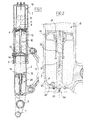
- the undercarriage comprises a box 1 connected to the aircraft, in which a rod 2 is mounted to slide sealing.
- the box carries part lower a lower bearing 3 having an inner surface in contact with the rod 2, and the rod 2 partially carries high an upper bearing 4 having an outer surface in contact with the casing 1.
- a compass 5 (which we see the beginning of the two branches) is mounted between the casing 1 and the rod 2 to prevent any rotation of the rod 2 about its axis by report to the caisson 1.
- the rod 2 forms a fork whose branches have bores 6 for to receive the axis of articulation of a balance carrying several wheels (not shown).
- the branches of the fork extend here beyond the bores 6 to present bores 7 for receiving the end of brake bars (not shown) stopping angularly the braking crowns that equip the wheels carried by the pendulum.
- a perforated tube 8 fixed at the top of the box 1 extends into it and carries at its lower end a diaphragm 9 having an outer surface that slides to sealing on the inner surface of the rod 2.
- the diaphragm 9 has rolling orifices 10, and a central orifice 11 in which extends a needle rolling 12 secured to the rod 2 by through a support 13 reported in the rod 2 by means of a rod and having passage orifices.
- a first separating piston 14 is mounted in the rod 2 for sliding sealing, the support 13 forming an end stop for said separator piston 14.
- a second separating piston 15 is disposed in the rod 2 for sliding sealing. As is better visible in FIG. 2, the second separator piston 15 slide on a column 16 attached to the end 2. The column 16 has at its upper end a limit stop 17 for the second separating piston 15.
- hydraulic fluid (symbolized by horizontal lines) completely fills the volume between the separating piston 14 and the diaphragm 9, as well as the annular volume extending between the outer wall of the rod 2 and the inner wall of the casing 1 between the two bearings 3,4. Hydraulic fluid partially fills the volume extending above the diaphragm 9.
- the rest of the internal volume of the undercarriage sets a first chamber 18 which extends between the first piston separator 14 and the second piston separator 15, and a second chamber 19 formed by the part of the volume above the diaphragm 9 not filled with fluid hydraulic system, and a third chamber 20 arranged under the second separating piston 15.
- the third chamber 20 is thus arranged in series with the first chamber 18.
- the first chamber 18 is filled with nitrogen (symbolized by points) at a pressure of about 120 bars, while the second room 19 is filled nitrogen at a pressure of the order of 20 bar.
- the third chamber 20 she is inflated to a pressure of 180 bar, so higher than the pressure of inflating the first adjacent chamber 18.
- the rod 2 is forced to sinking into the box 1.
- the hydraulic fluid is forced to pass through the orifices of rolling of the diaphragm 9. This rolling causes dissipation of energy by internal friction in the fluid hydraulic.
- the quantity of hydraulic fluid passing through through the diaphragm 9 decreases the volume of the second chamber 19, which causes the compression of the nitrogen contained in it and increases its pressure.
- the fluid lying above of the diaphragm 9 sees its pressure imposed by the pressure prevailing in the second chamber. is fluid located below the diaphragm 9, its pressure is imposed by the resistance opposed to the passage hydraulic fluid through the rolling orifices 9. When this pressure reaches the pressure for inflating the first chamber 18, the first piston separator 14 then moves, causing compression gas from the first chamber 15.
- Nitrogen contained in chambers 18,19 behaves as a spring whose effort follows a law substantially polytropic.
- the rod 2 finds a position of stable equilibrium in the caisson 1 under the effect of part of the weight of the aircraft to which the landing gear is submitted.
- the hydraulic fluid and the nitrogen contained in both chambers 18,19 are at the same pressure.
- the central undercarriage may have to bear a significant part of the weight of the aircraft, exceeding particular the limits for which it was designed.
- the second piston separator 15 is able to move when the pressure in the first chamber 18 reaches the inflation pressure of the third chamber 20.
- the third chamber 20 is a simple means safety limit to limit maximum forces developed by the lander.
- the displacement of the second separating piston 15 causes a rise in pressure in the third chamber 20, so that said displacement is easily detectable by means of a simple pressure sensor to detect the exceeding of a pressure threshold in the third bedroom 20.
- the column 16 comprises a central conduit 22 which opens in the first chamber 18, which makes it easy to ensure inflating said first chamber since the outside of the undercarriage, by means of a valve of inflation 24.
- Another inflation valve not shown is arranged directly on the rod 2 to allow inflation of the third bedroom 20.
- the second chamber 18 contains a small amount of hydraulic fluid, just enough to flush the upper end of column 16, and therefore the entrance of the central duct 22.
- the seals equipping the second separator piston 15 thus remain wet by this hydraulic fluid, which prevents their drying out.
- the leaks hydraulic fluid following this failure flow into the first chamber 18. The entire these leaks then flows into the central duct 22 of column 16 because of the outcrop of the end upper column 16 by the hydraulic fluid already present in the first chamber 18.
- a maintenance performed on the first chamber 18 can detect a seal failure of the first separator piston 14.
- the third chamber 20 contains a small amount of hydraulic fluid, just sufficient to flush the entrance of an auxiliary duct 23 in the base of column 16 and closed by a bleed screw 25.
- the presence of hydraulic fluid in the auxiliary duct 23, detected during a maintenance operation, is the sign of a failure one of the seals of the second separator piston 15.
Landscapes
- Engineering & Computer Science (AREA)
- General Engineering & Computer Science (AREA)
- Mechanical Engineering (AREA)
- Aviation & Aerospace Engineering (AREA)
- Fluid-Damping Devices (AREA)
Applications Claiming Priority (2)
| Application Number | Priority Date | Filing Date | Title |
|---|---|---|---|
| FR0404092A FR2869016B1 (fr) | 2004-04-19 | 2004-04-19 | Atterisseur a amortisseur trichambre |
| FR0404092 | 2004-04-19 |
Publications (1)
| Publication Number | Publication Date |
|---|---|
| EP1588939A1 true EP1588939A1 (de) | 2005-10-26 |
Family
ID=34942055
Family Applications (1)
| Application Number | Title | Priority Date | Filing Date |
|---|---|---|---|
| EP05290710A Withdrawn EP1588939A1 (de) | 2004-04-19 | 2005-03-31 | Fahrwerk mit einem Stossdämpfer mit drei Kammern |
Country Status (3)
| Country | Link |
|---|---|
| US (1) | US20050230887A1 (de) |
| EP (1) | EP1588939A1 (de) |
| FR (1) | FR2869016B1 (de) |
Cited By (2)
| Publication number | Priority date | Publication date | Assignee | Title |
|---|---|---|---|---|
| FR2917371A1 (fr) * | 2007-06-15 | 2008-12-19 | Messier Dowty Sa Sa | Amortisseur pour atterisseur d'aeronef |
| EP2287492A1 (de) * | 2009-08-19 | 2011-02-23 | HEMSCHEIDT FAHRWERKTECHNIK GmbH & Co. KG | Hydropneumatischer Kolbenspeicher |
Families Citing this family (8)
| Publication number | Priority date | Publication date | Assignee | Title |
|---|---|---|---|---|
| US20070087876A1 (en) * | 2005-10-19 | 2007-04-19 | Ward Michael C | Multi-stage spring for track tensioning system |
| FR2999529B1 (fr) * | 2012-12-19 | 2016-08-19 | Messier Bugatti Dowty | Atterrisseur equipe d'un piston separateur en matiere thermoplastique |
| JP6121888B2 (ja) * | 2013-09-27 | 2017-04-26 | 株式会社ショーワ | 懸架装置および懸架システム |
| US9618075B2 (en) * | 2014-10-22 | 2017-04-11 | Goodrich Corporation | Z-head piston for dual chamber shock struts |
| GB2563948A (en) | 2017-06-30 | 2019-01-02 | Airbus Operations Ltd | Aircraft landing gear assembly |
| GB2563945A (en) * | 2017-06-30 | 2019-01-02 | Airbus Operations Ltd | Aircraft landing gear assembly |
| FR3102524B1 (fr) * | 2019-10-29 | 2021-11-12 | Safran Landing Systems | Porte-diaphragme pour amortisseur de type oléopneumatique |
| FR3102522B1 (fr) * | 2019-10-29 | 2021-11-12 | Safran Landing Systems | Porte-diaphragme pour amortisseur de type oléopneumatique |
Citations (5)
| Publication number | Priority date | Publication date | Assignee | Title |
|---|---|---|---|---|
| FR2461852A1 (fr) * | 1979-07-17 | 1981-02-06 | Messier Hispano Sa | Perfectionnements aux amortisseurs et amortisseurs-verins notamment pour trains d'atterrissage d'aerodyne |
| US4506869A (en) * | 1980-08-29 | 1985-03-26 | Messier-Hispano-Bugatti | Dual chamber shock absorbers for aircrafts and the like |
| EP0341021A2 (de) * | 1988-05-04 | 1989-11-08 | Dowty Rotol Limited | Hydraulischer Stossdämpfer |
| JPH02109713A (ja) * | 1988-10-20 | 1990-04-23 | Tokico Ltd | サスペンション装置 |
| US5330132A (en) * | 1991-12-11 | 1994-07-19 | Messier-Bugatti | Force-limiting device for an aircraft landing gear shock absorber, and a shock absorber including such a device |
Family Cites Families (10)
| Publication number | Priority date | Publication date | Assignee | Title |
|---|---|---|---|---|
| US2959410A (en) * | 1958-10-27 | 1960-11-08 | Jarry Hydraulics | Double stage oleo-pneumatic shock absorber |
| US3246493A (en) * | 1963-12-24 | 1966-04-19 | Hupp Corp | Dry cleaning apparatus |
| US3533613A (en) * | 1967-11-02 | 1970-10-13 | Lockheed Aircraft Corp | Axially retractable landing gear |
| US3540683A (en) * | 1967-11-07 | 1970-11-17 | Lockheed Aircraft Corp | Dual air chambered shock strut |
| US3888436A (en) * | 1974-04-01 | 1975-06-10 | Boeing Co | Airplane landing gear shock absorber |
| FR2370196A2 (fr) * | 1976-02-04 | 1978-06-02 | Messier Hispano Sa | Perfectionnements aux amortisseurs-verins |
| GB2147683B (en) * | 1983-09-24 | 1986-10-01 | Bilstein August Gmbh Co Kg | Shock absorber, with electromagnetically biased pressure responsive valve |
| FR2601097B1 (fr) * | 1986-07-07 | 1990-07-06 | Messier Hispano Bugatti Sa | Amortisseur a adaptation de course residuelle |
| DE3818811A1 (de) * | 1988-06-03 | 1989-12-14 | Stabilus Gmbh | Gasfeder mit mehreren hintereinander angeordneten druckraeumen |
| FR2686857B1 (fr) * | 1992-02-04 | 1994-04-01 | Messier Bugatti | Amortisseur de jambe de train d'atterrissage d'aeronef. |
-
2004
- 2004-04-19 FR FR0404092A patent/FR2869016B1/fr not_active Expired - Lifetime
-
2005
- 2005-03-31 EP EP05290710A patent/EP1588939A1/de not_active Withdrawn
- 2005-04-19 US US11/109,371 patent/US20050230887A1/en not_active Abandoned
Patent Citations (5)
| Publication number | Priority date | Publication date | Assignee | Title |
|---|---|---|---|---|
| FR2461852A1 (fr) * | 1979-07-17 | 1981-02-06 | Messier Hispano Sa | Perfectionnements aux amortisseurs et amortisseurs-verins notamment pour trains d'atterrissage d'aerodyne |
| US4506869A (en) * | 1980-08-29 | 1985-03-26 | Messier-Hispano-Bugatti | Dual chamber shock absorbers for aircrafts and the like |
| EP0341021A2 (de) * | 1988-05-04 | 1989-11-08 | Dowty Rotol Limited | Hydraulischer Stossdämpfer |
| JPH02109713A (ja) * | 1988-10-20 | 1990-04-23 | Tokico Ltd | サスペンション装置 |
| US5330132A (en) * | 1991-12-11 | 1994-07-19 | Messier-Bugatti | Force-limiting device for an aircraft landing gear shock absorber, and a shock absorber including such a device |
Non-Patent Citations (1)
| Title |
|---|
| PATENT ABSTRACTS OF JAPAN vol. 0143, no. 23 (M - 0997) 11 July 1990 (1990-07-11) * |
Cited By (5)
| Publication number | Priority date | Publication date | Assignee | Title |
|---|---|---|---|---|
| FR2917371A1 (fr) * | 2007-06-15 | 2008-12-19 | Messier Dowty Sa Sa | Amortisseur pour atterisseur d'aeronef |
| WO2009010643A3 (fr) * | 2007-06-15 | 2009-03-19 | Messier Dowty Sa | Amortisseur pour atterrisseur d'aeronef |
| US8459417B2 (en) | 2007-06-15 | 2013-06-11 | Messier-Bugatti-Dowty | Shock-absorber for aircraft landing gear |
| EP2287492A1 (de) * | 2009-08-19 | 2011-02-23 | HEMSCHEIDT FAHRWERKTECHNIK GmbH & Co. KG | Hydropneumatischer Kolbenspeicher |
| US8746661B2 (en) | 2009-08-19 | 2014-06-10 | Hemscheidt Fahrwerktechnik Gmbh & Co. Kg | Hydro-pneumatic piston accumulator |
Also Published As
| Publication number | Publication date |
|---|---|
| FR2869016A1 (fr) | 2005-10-21 |
| US20050230887A1 (en) | 2005-10-20 |
| FR2869016B1 (fr) | 2007-07-20 |
Similar Documents
| Publication | Publication Date | Title |
|---|---|---|
| EP2155551B1 (de) | Stossdämpfer für ein flugzeugfahrwerk | |
| EP2440806B1 (de) | Stossdämpfer und mit solch einem stossdämpfer versehenes fahrwerk | |
| FR2997151A1 (fr) | Amortisseur avec fonction ressort associee | |
| EP2326856B1 (de) | Überdruck- und anschlagdetektor für einen stossdämpfer oder dergleichen | |
| EP1588939A1 (de) | Fahrwerk mit einem Stossdämpfer mit drei Kammern | |
| FR2609128A1 (fr) | Amortisseur a compensation de charge | |
| FR2554415A1 (fr) | Atterrisseurs pour aeronef, notamment pour helicoptere | |
| EP1574427B1 (de) | Fahrwerk mit einem Gasbehälter und Wartungsverfahren dafür | |
| FR2964434A1 (fr) | Amortisseur a haut pouvoir dissipatif et pratiquement sans huile | |
| EP3085988B1 (de) | Luftfederungssystem | |
| EP4051923A1 (de) | Membranhalter für einen ölpneumatischen stossdämpfer | |
| CA2627224C (fr) | Amortisseur d'atterrisseur a retenue positive en position retractee et surcourse de crash | |
| EP4110693B1 (de) | Messen des drucks in der regelkammer eines gekapselten stossdämpfers in einem flugzeugfahrwerk | |
| WO2009146891A1 (fr) | Dispositif de purge pour ensemble monte et procede de degonflage d'un ensemble monte | |
| FR2999528A1 (fr) | Tube support de diaphragme en thermoplastique | |
| FR3022528A1 (fr) | Systeme de suivi a la manutention d'un moteur d'aeronef | |
| FR2740402A1 (fr) | Reservoir de carburant de vehicule automobile muni d'un dispositif de mise a l'air libre perfectionne et dispositif de mise a l'air libre perfectionne | |
| EP1140628A1 (de) | Nutzlasthalterung in einer trägerrakete | |
| EP0242290B1 (de) | Hydraulische Abwurfvorrichtung für Lasten an Trägerfahrzeugen | |
| EP1693270A1 (de) | Sekundärfedersystem, mit Notfeder, für Schienenfahrzeuge. | |
| FR2723624A1 (fr) | Amortisseur hydraulique pressurise muni d'un element de butee de detente immobilise axialement | |
| FR2739668A1 (fr) | Dispositif perfectionne d'obturation a guide centreur lubrifie pour tube d'amortisseur hydraulique pressurise | |
| EP0516528B1 (de) | Sicherheitsventil für den Entlüftungskreislauf eines Kfz-Kraftstoffbehälters | |
| FR2859162A1 (fr) | Dispositif de blocage de tige de selle | |
| FR3039606A1 (fr) | Dispositif d’amortissement a butee de detente hydraulique a piece d’extremite a canaux de passage de fluide |
Legal Events
| Date | Code | Title | Description |
|---|---|---|---|
| PUAI | Public reference made under article 153(3) epc to a published international application that has entered the european phase |
Free format text: ORIGINAL CODE: 0009012 |
|
| AK | Designated contracting states |
Kind code of ref document: A1 Designated state(s): AT BE BG CH CY CZ DE DK EE ES FI FR GB GR HU IE IS IT LI LT LU MC NL PL PT RO SE SI SK TR |
|
| AX | Request for extension of the european patent |
Extension state: AL BA HR LV MK YU |
|
| 17P | Request for examination filed |
Effective date: 20060327 |
|
| AKX | Designation fees paid |
Designated state(s): DE ES FR GB IT |
|
| STAA | Information on the status of an ep patent application or granted ep patent |
Free format text: STATUS: THE APPLICATION IS DEEMED TO BE WITHDRAWN |
|
| 18D | Application deemed to be withdrawn |
Effective date: 20101001 |