EP0341021A2 - Hydraulischer Stossdämpfer - Google Patents
Hydraulischer Stossdämpfer Download PDFInfo
- Publication number
- EP0341021A2 EP0341021A2 EP89304400A EP89304400A EP0341021A2 EP 0341021 A2 EP0341021 A2 EP 0341021A2 EP 89304400 A EP89304400 A EP 89304400A EP 89304400 A EP89304400 A EP 89304400A EP 0341021 A2 EP0341021 A2 EP 0341021A2
- Authority
- EP
- European Patent Office
- Prior art keywords
- casing member
- section
- shock absorber
- volume
- hydraulic shock
- Prior art date
- Legal status (The legal status is an assumption and is not a legal conclusion. Google has not performed a legal analysis and makes no representation as to the accuracy of the status listed.)
- Withdrawn
Links
Images

Classifications
-
- B—PERFORMING OPERATIONS; TRANSPORTING
- B64—AIRCRAFT; AVIATION; COSMONAUTICS
- B64C—AEROPLANES; HELICOPTERS
- B64C25/00—Alighting gear
- B64C25/32—Alighting gear characterised by elements which contact the ground or similar surface
- B64C25/58—Arrangements or adaptations of shock-absorbers or springs
- B64C25/60—Oleo legs
-
- F—MECHANICAL ENGINEERING; LIGHTING; HEATING; WEAPONS; BLASTING
- F16—ENGINEERING ELEMENTS AND UNITS; GENERAL MEASURES FOR PRODUCING AND MAINTAINING EFFECTIVE FUNCTIONING OF MACHINES OR INSTALLATIONS; THERMAL INSULATION IN GENERAL
- F16F—SPRINGS; SHOCK-ABSORBERS; MEANS FOR DAMPING VIBRATION
- F16F9/00—Springs, vibration-dampers, shock-absorbers, or similarly-constructed movement-dampers using a fluid or the equivalent as damping medium
- F16F9/06—Springs, vibration-dampers, shock-absorbers, or similarly-constructed movement-dampers using a fluid or the equivalent as damping medium using both gas and liquid
- F16F9/063—Springs, vibration-dampers, shock-absorbers, or similarly-constructed movement-dampers using a fluid or the equivalent as damping medium using both gas and liquid comprising a hollow piston rod
Definitions
- This invention relates to a hydraulic shock absorber, and, is particularly, related to hydraulic shock absorbers for use with aircraft and which utilises a gas spring effect.
- shock absorbers which have been used in conjunction with aircraft landing gear suspension arrangements have utilised a gas spring effect in their operational characteristics.
- the build up in gas results in the shock absorber operating below its maximum operating efficiency. This is particularly true when the shock absorber is subjected to a rapid oscillatory cycle, for example during taxiing of an aircraft on a bumpy airfield.
- the present invention is concerned with eliminating, or at the very least drastically reducing, the cavitation problems and the effects that cavitation causes on the operation of the shock absorber.
- a hydraulic shock absorber includes: - a first casing member telescopically and sealingly engaged with a second casing member, said second casing member having a first section of reduced diameter in comparison to a second section; and - an oil reservoir defined by the first and second casing members, which is divided into two distinct volumes by a one way restrictor means attached to the second casing member; wherein the one way restrictor means acts to restrict the flow of oil from the volume of the oil reservoir defined by the first casing member and the second section of the second casing member to the volume of the reservoir defined by the first casing member and the first section of the second casing member only and the volume of the oil reservoir defined by the first casing member and the first section of the second casing member is further divided into two sections by a two way restrictor means.
- the oil reservoir has a first volume of the oil reservoir which is defined by the first casing member and the first section of the second casing member, and a second volume of the oil reservoir which is defined by the first casing member and the second section of the second casing member.
- the volume of the oil in the second volume of the oil reservoir is at a base level, which may be effectively substantially zero.
- the first and second casing members move relative to one another so as to cause oil to flow from the first volume to the second volume of the oil reservoir.
- the difference in the diameter of the respective sections of the second casing member, which with the first casing member defines the respective volume of the oil reservoir, between the first and second volumes of the oil reservoir means that during compression of the shock absorber no cavitation is caused, as a result of net positive pressurisation of the shock absorber. Primarily, this is due to the difference in diameters, and the resultant volume of the oil reservoir in total between the extended and compressed states.
- the site of the one way restrictor with regard to the two way restrictor is a further contributory factor which has to be taken into consideration.
- the hydraulic shock absorber is provided with a gaseous volume in the volume of the oil reservoir which is defined by the first casing member and the first section of the second casing member. In this way a gas spring effect is built into the hydraulic shock absorber.
- the hydraulic shock absorber further includes a slidable piston mounted within the second casing member, and separating the oil reservoir from a gaseous capacity.
- the or each, gaseous volume consists of a volume of substantially inert gas such as nitrogen.
- This invention also includes an aircraft landing gear incorporating a hydraulic shock absorber made in accordance with the present invention.
- an hydraulic shock absorber 1 includes: - an outer casing member 2; - an inner casing member 3; - and oil reservoir 4; - a one-way restrictor 5, having a plate valve 6; - a two way restrictor 7; and - a slidable piston 8 mounted in the inner casing member 3.
- the outer casing member 2 comprises a cylindrical side wall 9 and an end wall 10, and is provided with: - an inflation valve 11; - an internal circumferentially extending bearing 12; and - an inwardly directed lip 13.
- the inner casing member 3 comprises a stepped cylinder side wall 14 and an end wall 15.
- the inner casing member 3 is provided with an upper section 16 and a lower section 17.
- the inner casing member 3 is provided with: - a circumferentially extending shoulder 18 positioned in the vicinity of the change in diameter between the upper section 16 and the lower section 17; - an inflation valve 19; - an inwardly turned lip 20; and - an internally directed abutment member 21.
- the inner casing member 3 is telescopically mounted within the outer casing member 2, so that the lower section 17 thereof projects from the outer casing member 2, and the shoulder 18 is allowed to travel between the shelf 12 and the lip section 13.
- the two casing members are mounted so that the lower section 17 of the inner casing member is slidably engageable with the lip section 13 of the outer casing member, and the upper section 16 of the inner casing member 3 is slidably engageable with the abutment member 21 of the outer casing member 2.
- the two end walls of the respective casing members are at opposing ends of the shock absorber.
- the lip 13 of the outer casing member 2 is provided with two sealing members 22, 23 which engage with the inner casing member 3.
- the one way restrictor 5 and plate valve 6 are mounted on the shoulder 18 of the inner casing member 3, which is also provided with a sealing member 28 which engages with the outer casing member 2.
- the sealing member 28 so provides a sealing contact between the inner casing member 3 and the outer casing member 2.
- the two way restrictor 7 is mounted in the shelf member 12, which is in sliding contact with the upper section 16 of the inner casing member 3.
- oil reservoir 4 is divided into three distinct sections 4 a , 4 b and 4 c .
- a stop member 29 is provided on the lower section 17 of the inner casing member 3. This stop member 29 engages with the lip section 13 of the outer casing member 2 to prevent over extension.
- the slidable piston 8 is mounted in the inner casing member 3, so that it may travel between the inwardly turned lip 20 and the abutment member 21.
- Two sealing members 24, 25 are provided on the slidable piston 8, so as to prevent the ingress of oil past the piston.
- the volume 27 defined by the inner casing member 3, and below the slidable piston 8 is also filled with nitrogen.
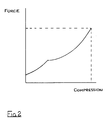
- the volumes 26, 27 of nitrogen with the action of the slidable piston 8 provide the shock absorber with a two stage gas spring effect under compression.
- shock absorber is essentially identical to those already known in the industry.
Landscapes
- Engineering & Computer Science (AREA)
- General Engineering & Computer Science (AREA)
- Mechanical Engineering (AREA)
- Aviation & Aerospace Engineering (AREA)
- Fluid-Damping Devices (AREA)
Applications Claiming Priority (2)
| Application Number | Priority Date | Filing Date | Title |
|---|---|---|---|
| GB888810538A GB8810538D0 (en) | 1988-05-04 | 1988-05-04 | Hydraulic shock absorber |
| GB8810538 | 1988-05-04 |
Publications (2)
| Publication Number | Publication Date |
|---|---|
| EP0341021A2 true EP0341021A2 (de) | 1989-11-08 |
| EP0341021A3 EP0341021A3 (de) | 1990-04-11 |
Family
ID=10636338
Family Applications (1)
| Application Number | Title | Priority Date | Filing Date |
|---|---|---|---|
| EP89304400A Withdrawn EP0341021A3 (de) | 1988-05-04 | 1989-05-02 | Hydraulischer Stossdämpfer |
Country Status (4)
| Country | Link |
|---|---|
| US (1) | US4995597A (de) |
| EP (1) | EP0341021A3 (de) |
| CA (1) | CA1325644C (de) |
| GB (1) | GB8810538D0 (de) |
Cited By (2)
| Publication number | Priority date | Publication date | Assignee | Title |
|---|---|---|---|---|
| EP1588939A1 (de) * | 2004-04-19 | 2005-10-26 | Messier-Dowty S.A. | Fahrwerk mit einem Stossdämpfer mit drei Kammern |
| WO2024028573A1 (en) * | 2022-08-04 | 2024-02-08 | Safran Landing Systems UK Limited | Aircraft landing gear shock absorber strut |
Families Citing this family (9)
| Publication number | Priority date | Publication date | Assignee | Title |
|---|---|---|---|---|
| US5201244A (en) * | 1992-02-27 | 1993-04-13 | Stewart John V | Bicycle handlebar stem extender |
| US5992582A (en) * | 1994-04-19 | 1999-11-30 | Lou; Zheng | Electrorheological rotary pure-shear damping devices |
| US5944283A (en) * | 1997-12-05 | 1999-08-31 | Cartercopters, Llc | Crashworthy landing gear shock |
| FR2917371B1 (fr) * | 2007-06-15 | 2009-11-20 | Messier Dowty Sa | Amortisseur pour atterisseur d'aeronef |
| AU2011200411A1 (en) * | 2010-10-15 | 2012-05-03 | Y.S.S. (Thailand) Co., Ltd. | A shock absorber using air pressure |
| DE202014010614U1 (de) * | 2014-01-29 | 2016-02-02 | Hemscheidt Fahrwerktechnik Gmbh & Co. Kg | Spanneinrichtung und Bauteil mit einer derartigen Spanneinrichtung |
| USD811281S1 (en) | 2015-12-21 | 2018-02-27 | Y.S.S. (Thailand) Co., Ltd. | Shock absorber |
| US20170323240A1 (en) | 2016-05-06 | 2017-11-09 | General Electric Company | Computing system to control the use of physical state attainment with inspection |
| ES2796000T3 (es) * | 2017-04-20 | 2020-11-25 | Safran Landing Systems Uk Ltd | Puntal amortiguador de tren de aterrizaje de aeronave |
Family Cites Families (6)
| Publication number | Priority date | Publication date | Assignee | Title |
|---|---|---|---|---|
| GB585261A (en) * | 1945-02-05 | 1947-02-03 | Automotive Prod Co Ltd | Improvements in or relating to telescopic shock absorbers |
| GB629565A (en) * | 1947-06-05 | 1949-09-22 | British Messier Ltd | Improvements in or relating to vehicle suspension systems |
| FR2264223B1 (de) * | 1974-03-14 | 1977-06-17 | Peugeot & Renault | |
| FR2497896A1 (fr) * | 1980-08-29 | 1982-07-16 | Messier Hispano Sa | Amortisseur |
| US4381857A (en) * | 1980-12-08 | 1983-05-03 | Lockheed Corporation | Programmed oleo-pneumatic shock absorber |
| FR2601097B1 (fr) * | 1986-07-07 | 1990-07-06 | Messier Hispano Bugatti Sa | Amortisseur a adaptation de course residuelle |
-
1988
- 1988-05-04 GB GB888810538A patent/GB8810538D0/en active Pending
-
1989
- 1989-05-02 US US07/347,383 patent/US4995597A/en not_active Expired - Lifetime
- 1989-05-02 EP EP89304400A patent/EP0341021A3/de not_active Withdrawn
- 1989-05-03 CA CA000598564A patent/CA1325644C/en not_active Expired - Lifetime
Cited By (2)
| Publication number | Priority date | Publication date | Assignee | Title |
|---|---|---|---|---|
| EP1588939A1 (de) * | 2004-04-19 | 2005-10-26 | Messier-Dowty S.A. | Fahrwerk mit einem Stossdämpfer mit drei Kammern |
| WO2024028573A1 (en) * | 2022-08-04 | 2024-02-08 | Safran Landing Systems UK Limited | Aircraft landing gear shock absorber strut |
Also Published As
| Publication number | Publication date |
|---|---|
| GB8810538D0 (en) | 1988-06-08 |
| EP0341021A3 (de) | 1990-04-11 |
| US4995597A (en) | 1991-02-26 |
| CA1325644C (en) | 1993-12-28 |
Similar Documents
| Publication | Publication Date | Title |
|---|---|---|
| US5181699A (en) | Impact absorber | |
| US4381857A (en) | Programmed oleo-pneumatic shock absorber | |
| US6311962B1 (en) | Shock absorber with external air cylinder spring | |
| US5538276A (en) | Tunable air spring | |
| EP0119197B1 (de) | Endanschlag für einen teleskopischen hydraulischen Stossdämpfer | |
| CN1918400B (zh) | 阻尼器 | |
| EP0607545A1 (de) | Stossdämpfer | |
| US20030051957A1 (en) | Shock absorber with a floating piston | |
| US4995597A (en) | Hydraulic shock absorber with telescopic casings | |
| EP0120005B1 (de) | Stossdämpfer mit einem hydromechanischen endanschlag | |
| US20090260902A1 (en) | Suspension Unit | |
| EP0260968A2 (de) | Stossdämpfer mit unter Gasdruck stehender Rückstellfeder | |
| US6676076B1 (en) | Two stage shock strut | |
| US3426651A (en) | Air-oil suspension | |
| WO2002045979A2 (en) | Method of supplying suspension struts | |
| WO2000005482A1 (en) | Tool string shock absorber | |
| US6032933A (en) | Self-pumping hydropneumatic spring strut with internal level regulation | |
| RU2547023C2 (ru) | Амортизатор с повышенной диссипативной способностью и практически без масла | |
| US3731914A (en) | Double ended spring shock absorber | |
| US2934332A (en) | Shock absorber | |
| US20040060787A1 (en) | Cylinder apparatus | |
| EP0129363B1 (de) | Feder | |
| US5325943A (en) | Variable orifice oil/gass damper for aircraft landing gear | |
| US3582058A (en) | Linear-type vibration dampener | |
| CA2028468A1 (en) | Hydraulic shock absorber |
Legal Events
| Date | Code | Title | Description |
|---|---|---|---|
| PUAI | Public reference made under article 153(3) epc to a published international application that has entered the european phase |
Free format text: ORIGINAL CODE: 0009012 |
|
| AK | Designated contracting states |
Kind code of ref document: A2 Designated state(s): DE ES FR GB IT |
|
| PUAL | Search report despatched |
Free format text: ORIGINAL CODE: 0009013 |
|
| AK | Designated contracting states |
Kind code of ref document: A3 Designated state(s): DE ES FR GB IT |
|
| 17P | Request for examination filed |
Effective date: 19901010 |
|
| 17Q | First examination report despatched |
Effective date: 19920228 |
|
| STAA | Information on the status of an ep patent application or granted ep patent |
Free format text: STATUS: THE APPLICATION IS DEEMED TO BE WITHDRAWN |
|
| 18D | Application deemed to be withdrawn |
Effective date: 19920910 |