EP0607545A1 - Stossdämpfer - Google Patents
Stossdämpfer Download PDFInfo
- Publication number
- EP0607545A1 EP0607545A1 EP93119459A EP93119459A EP0607545A1 EP 0607545 A1 EP0607545 A1 EP 0607545A1 EP 93119459 A EP93119459 A EP 93119459A EP 93119459 A EP93119459 A EP 93119459A EP 0607545 A1 EP0607545 A1 EP 0607545A1
- Authority
- EP
- European Patent Office
- Prior art keywords
- chamber
- piston
- fluid
- shock absorber
- damping
- Prior art date
- Legal status (The legal status is an assumption and is not a legal conclusion. Google has not performed a legal analysis and makes no representation as to the accuracy of the status listed.)
- Granted
Links
Images


Classifications
-
- F—MECHANICAL ENGINEERING; LIGHTING; HEATING; WEAPONS; BLASTING
- F16—ENGINEERING ELEMENTS AND UNITS; GENERAL MEASURES FOR PRODUCING AND MAINTAINING EFFECTIVE FUNCTIONING OF MACHINES OR INSTALLATIONS; THERMAL INSULATION IN GENERAL
- F16F—SPRINGS; SHOCK-ABSORBERS; MEANS FOR DAMPING VIBRATION
- F16F9/00—Springs, vibration-dampers, shock-absorbers, or similarly-constructed movement-dampers using a fluid or the equivalent as damping medium
- F16F9/06—Springs, vibration-dampers, shock-absorbers, or similarly-constructed movement-dampers using a fluid or the equivalent as damping medium using both gas and liquid
- F16F9/062—Bi-tubular units
-
- F—MECHANICAL ENGINEERING; LIGHTING; HEATING; WEAPONS; BLASTING
- F16—ENGINEERING ELEMENTS AND UNITS; GENERAL MEASURES FOR PRODUCING AND MAINTAINING EFFECTIVE FUNCTIONING OF MACHINES OR INSTALLATIONS; THERMAL INSULATION IN GENERAL
- F16F—SPRINGS; SHOCK-ABSORBERS; MEANS FOR DAMPING VIBRATION
- F16F9/00—Springs, vibration-dampers, shock-absorbers, or similarly-constructed movement-dampers using a fluid or the equivalent as damping medium
- F16F9/06—Springs, vibration-dampers, shock-absorbers, or similarly-constructed movement-dampers using a fluid or the equivalent as damping medium using both gas and liquid
- F16F9/064—Units characterised by the location or shape of the expansion chamber
- F16F9/065—Expansion chamber provided on the upper or lower end of a damper, separately there from or laterally on the damper
-
- F—MECHANICAL ENGINEERING; LIGHTING; HEATING; WEAPONS; BLASTING
- F16—ENGINEERING ELEMENTS AND UNITS; GENERAL MEASURES FOR PRODUCING AND MAINTAINING EFFECTIVE FUNCTIONING OF MACHINES OR INSTALLATIONS; THERMAL INSULATION IN GENERAL
- F16F—SPRINGS; SHOCK-ABSORBERS; MEANS FOR DAMPING VIBRATION
- F16F9/00—Springs, vibration-dampers, shock-absorbers, or similarly-constructed movement-dampers using a fluid or the equivalent as damping medium
- F16F9/10—Springs, vibration-dampers, shock-absorbers, or similarly-constructed movement-dampers using a fluid or the equivalent as damping medium using liquid only; using a fluid of which the nature is immaterial
- F16F9/14—Devices with one or more members, e.g. pistons, vanes, moving to and fro in chambers and using throttling effect
- F16F9/16—Devices with one or more members, e.g. pistons, vanes, moving to and fro in chambers and using throttling effect involving only straight-line movement of the effective parts
- F16F9/18—Devices with one or more members, e.g. pistons, vanes, moving to and fro in chambers and using throttling effect involving only straight-line movement of the effective parts with a closed cylinder and a piston separating two or more working spaces therein
- F16F9/185—Bitubular units
-
- F—MECHANICAL ENGINEERING; LIGHTING; HEATING; WEAPONS; BLASTING
- F16—ENGINEERING ELEMENTS AND UNITS; GENERAL MEASURES FOR PRODUCING AND MAINTAINING EFFECTIVE FUNCTIONING OF MACHINES OR INSTALLATIONS; THERMAL INSULATION IN GENERAL
- F16F—SPRINGS; SHOCK-ABSORBERS; MEANS FOR DAMPING VIBRATION
- F16F9/00—Springs, vibration-dampers, shock-absorbers, or similarly-constructed movement-dampers using a fluid or the equivalent as damping medium
- F16F9/32—Details
- F16F9/50—Special means providing automatic damping adjustment, i.e. self-adjustment of damping by particular sliding movements of a valve element, other than flexions or displacement of valve discs; Special means providing self-adjustment of spring characteristics
- F16F9/516—Special means providing automatic damping adjustment, i.e. self-adjustment of damping by particular sliding movements of a valve element, other than flexions or displacement of valve discs; Special means providing self-adjustment of spring characteristics resulting in the damping effects during contraction being different from the damping effects during extension, i.e. responsive to the direction of movement
Definitions
- This invention relates to a shock absorber and more particularly to an improved shock absorber that permits better control of damping in both directions of operation.
- shock absorbers for a wide variety of applications.
- Such shock absorbers include a cylinder in which a piston is supported for reciprocation to define two fluid chambers.
- a piston rod is connected to the piston and extends through one of the chambers for connection to one of the two elements to be suspended.
- the cylinder is connected to the other of the two elements so that the volume of the two chambers vary as the elements move relative to each other.
- damping valves are provided within the assembly one of which permits controlled flow from the chamber in which the piston rod extends to the other chamber upon extension of the shock absorber.
- the other chamber is conencted to a reservoir and a further valve means is provided in this connection for controlling the damping flow in the other direction.
- a disadvantage with this type of construction is that when the device is undergoing a compression stroke, the actual volume of the fluid for use in the shock absorbing function that is displaced by the piston rod in the chamber through which it extends.
- shock absorber is frequently used in vehicle suspension systems and it is desirable to provide a relatively low damping force under low piston speeds so as to improve ride quality.
- vehicles are frequently driven over rough roads and particularly at high speeds and when this is the case then damping forces must be substantially increased.
- the shock absorber should allow use for vehicle suspension systems wherein damping can be effectively controlled in both directions with a compact and relatively simple constructions.
- a shock absorber as indicated above is improved in that an annular piston being slideably supported in said outer cylinder defining said third fluid chamber, said annular piston being coupled for at least a portion of its stroke to the piston rod of the piston slideable in the inner cylinder, said third fluid chamber being fluidly connected to a reservoir chamber under the control of another damping valve means.
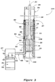
- Figure 1 is partially schematic cross-sectional view taken through a shock absorber constructed in accordance with a first embodiment of the invention.
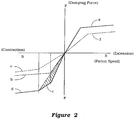
- Figure 2 is a damping diagram showing how the embodiment of Figure 1 provides more effective damping than convention types of tubular shock absorbers.
- Figure 3 is a partially schematic cross-sectional view, in part similar to Figure 1, and shows a second embodiment of the invention.
- Figure 4 is a partially schematic cross-sectional view, in part similar to Figures 1 and 3, and shows a third embodiment of the invention.
- Figure 5 is a partially schematic cross-sectional view, in part similar to Figures 1, 3 and 4, and shows a fourth embodiment of the invention.
- a shock absorber constructed in accordance with a first embodiment of the invention is identified generally by the reference numeral 11.
- the first shock absorber 11 includes an inner cylinder 12 that is closed at its opposite ends in a suitable manner by end caps 13 and 14.
- a piston 15 is slidably supported within a cylinder bore 16 formed by the inner cylinder 12 and divides the inner cylinder 12 into an upper or first fluid chamber 17 and a lower or second fluid chamber 18.
- the chambers 17 and 18 are filled with a suitable hydraulic fluid, designated also as working fluid. Normally hydraulic oil is being used.
- a piston rod 19 is affixed in a suitable manner to the piston 15 and extends through the chamber 17 and end cap 14 to provide an end portion 21 that is affixed to one of two relatively movable elements, the movement of which is to be damped by the shock absorber 11.
- the piston rod end 21 may be connected to a vehicle body in a well known manner.
- the inner cylinder 12 and specifically its end cap 13 is affixed to a wheel suspending element of the vehicle so that the piston 15 will be displaced upon movment of the wheel relative to the vehicle body, as is well known in this art.
- a first shock absorbing valve assembly comprised of a check valve 22 and a flow restricting valve 23 are disposed in the piston 15 for permitting flow from the chamber 17 to the chamber 18 upon expansion of the piston 15 within the cylinder 12 caused by upward movement of the piston rod 21. It should be noted that during such upward movement fluid will be displaced from the chamber 17 into the chamber 18 and the amount of fluid displaced will be equivalent to the difference between the diameter of the cylinder bore 16 and the outer peripheral diameter of the piston rod 19 and the distance of travel. The lower chamber 18 does not have a piston rod in it and the fluid displaced from the chamber 17 will not be sufficient to make up this volume.
- an accumulator or reservoir type of device indicated generally by the referencce numeral 24 which communicates with the lower chamber 18 through a conduit 25.
- the reservoir 24 has an internal volume that is partially filled with a hydraulic fluid 26 and which is contained above a floating piston 27 which is maintained in contact with the liquid by means of high pressure gas contained in a chamber 28 beneath the piston 27. Normally, nitrogen gas is provided for this purpose.
- a relatively light check valve 29 permits free flow from the reservoir chamber containing the hydraulic fluid 26 to the second chamber 18 when the upward movement of the piston 15 occurs, as aforenoted.
- a restricted orifice or flow controlling valve 31 is disposed so as to permit flow from the chamber 18 back into the accumulator chamber 26 when the piston 15 moves downwardly.
- the damping valve 31 is normally provided to control the damping force on the movement of the suspended elements in this direction.
- that can provide certain disadvantages as may be understood by reference to Figure 2.
- the solid line curve a shows the damping force in response to speed of the piston 15 in the extension direction and this is the desired degree of damping.
- a conventional shock absorber operating in the opposite or contractioned direction, it must be necessary to either increase the diameter of the piston rod 19 or substantially restrict the size of the orifice 31 in which case the damping curve as shown by the curve c-f will result.
- an outer cylinder 32 is telscopically received around the inner cylinder 12 and defines therebetween a third fluid chamber 33.
- This chamber 33 is closed at its lower end by the end plate 13.
- An annular piston 34 is affixed for movement with the upper end of the piston rod 19 by an end plate 35 of a disk-like configuration.
- the upper end of the chamber 33 around this annular piston 34 is sealed by means of a pair of annular inner and outer seals 36 and 37 which are disposed between the inner periphery of the annular piston 34 and the enclosure 14 and the outer periphery of the annular piston 34 and the outer cylinder 32, respectively.
- This consturction provides an air volume 38 between the disk 34, inner periphery of the annular piston 34 and end plate 14.
- At atmospheric vent 39 having a filter 41 permits air to flow in and out of this chamber 38 without restriction.
- a pair of cylindrical guides 42 and 44 are disposed between the inner periphery of the outer cylinder 32 and the outer periphery of the annular piston 43 so as to support its sliding movement. This defines an outer chamber 45 between the outer periphery of the annular piston 34 and the outer shell 32.
- a fluid passage 46 extends through a lower portion of the annular piston 34 so that the entire chamber 33 may be filled with hydraulic fluid. This hydraulic fluid may be of a different nature than the hydraulic fluid which fills the chamber 17 and 18 of the inner cylinder 12 so as to provide different degrees of damping, if desired.
- a second accumulator chamber or rservoir 47 is provided which communicates with the annular third fluid chamber 33 through a conduit 48. Like the first reservoir 24, the second reservoir 47 has a fluid chamber 49 which is filled with the same fluid as the third fluid chamber 33.
- a floating piston 51 urged by a compressed inert gas such as nitrogen within a chamber 52 normally maintains the fluid tight in said working fluid chamber 48.
- a damping arrangement for controlling the flow from the third chamber 33 to the reservoir chamber 49 and this includes a damping type of valve 53 which may comprise a fixed or variable orifice and which has damping curve as shown by the curve b in Figure 2. That is, when the piston rod 21 is moving downwardly to drive the piston 15 downwardly, at the same time, the annular piston 34 will move downwardly and displace fluid from the third fluid chamber 33 through the damping valve 53 into the reservoir chamber 49.
- the damping force in this construction in the contraction direction thus is the sum of the damping force c provided by the restriction or shock-absorbing valve 31 (curve b) and that of the damping or shock absorber valve 53 (curve c) which combined curve is shown at d.
- a greater degree of damping as indicated by the shaded line area c in Figure 2 is possible with this arrangement.
- FIGURE 3 A shock absorber constructed in accordance with a second embodiment of the invention is shown if FIGURE 3 and is identified generally by the reference numeral 101.
- the shock absorber 101 differs from the shock absorber 11 of the embodiment of FIGURES 1 and 2 only in the way in which makeup fluid is supplied to the chamber 18 so as to accommodate the different displacement of the piston rod 19. For that reason, components of this embodiment which are the same as the previously described embodiment have been identified by the same reference numeral and will be described again only insofar as is necessary to understand the construction and operation of this embodiment.
- a floating piston 102 is provided at the lower end of the lower, second fluid chamber 18 and is held in positon by means of high pressure gas contained within a chamber 103.
- a shock absorbing valve or orifice 104 is positioned in the piston 15 downstream of the check valve 30.
- the second fluid chamber 18 simultaneously forms the reservoir chamber corresponding to that of the reservoir chamber 24 in Figure 1.
- FIGURE 4 A shock absorber constructed in accordance with a third embodiment of the invention is shown in FIGURE 4 and is identified generally by the reference numeral 151.
- This shock absorber 151 differs from the previously described embodiments in that a single reservoir 47 is provided for both of the second and third fluid chambers 18 and 33 and to this end these chambers communicate with each other and hence must be filled with the same type of hydraulic fluid, unlike those of the previously described embodiments. Since the construction of this embodiment is substantially the same as in that embodiment have been identified by the same reference numerals and will not be described again.
- a fluid passageway 152 extends between the lower end of the second fluid chamber 18 and the third fluid chamber 33.
- FIGURE 5 A shock absorber constructed in accordance to the fourth embodiment of the invention is depicted in FIGURE 5 and is indicated generally by the reference numeral 201.
- This shock absorber 201 is similar to the previously described embodiments and differs from those embodiments only in the way the reservoir is provided for the second lower shock absorbing chamber 18 of the inner cylinder 12. For that reason, components of this embodiment which are the same as those previously described are substantially the same have again been identified by the same reference numerals and will be described again only insofar as is necessary to understand the construction and operation of this embodiment.
- an intermediate annular cylinder 202 is interposed between the outer surface of the inner cylinder 12 and the inner surface of the outer cylinder 32.
- the third fluid hcamber 33 is defined between the outer surface of the intermediate cylinder 202 and the inner surface of the outer cylinder 32.
- the area between the inner surface of the intermediate cylinder 202 and the outer surface of the inner cylinder 12 defines a reservoir volume 203 which is partially filled with hydraulic fluid.
- a chamber 204 above this fluid is filled with an inert gas such as nitrogen under relatively high pressure.
- An opening 205 in the lower portion of the inner cylinder 12 communicates this reservoir chamber 203 with a further chamber 206 formed beneath a piston-like disk 207 fixed in the inner cylinder 12.
- This disk 207 is provided with a check valve 208 which permits free flow from the chamber 206 to the chamber 18 and a combined check valve 209 and a shock absorber valve or restriction 211 which permits damping flow from the chamber 18 to the reservoir chamber 206 as with the previously described embodiments upon downward movement of this piston 15.
- this embodiment has all of the advantages of those previously described and also provides a more compact construction.
Applications Claiming Priority (2)
| Application Number | Priority Date | Filing Date | Title |
|---|---|---|---|
| JP34515192A JP3280725B2 (ja) | 1992-12-02 | 1992-12-02 | 筒型ショックアブソーバ |
| JP345151/92 | 1992-12-02 |
Publications (2)
| Publication Number | Publication Date |
|---|---|
| EP0607545A1 true EP0607545A1 (de) | 1994-07-27 |
| EP0607545B1 EP0607545B1 (de) | 1998-03-18 |
Family
ID=18374630
Family Applications (1)
| Application Number | Title | Priority Date | Filing Date |
|---|---|---|---|
| EP93119459A Expired - Lifetime EP0607545B1 (de) | 1992-12-02 | 1993-12-02 | Stossdämpfer |
Country Status (4)
| Country | Link |
|---|---|
| US (1) | US5593007A (de) |
| EP (1) | EP0607545B1 (de) |
| JP (1) | JP3280725B2 (de) |
| DE (1) | DE69317541T2 (de) |
Cited By (9)
| Publication number | Priority date | Publication date | Assignee | Title |
|---|---|---|---|---|
| DE29509869U1 (de) * | 1995-06-17 | 1996-10-17 | Huss Maschfab Gmbh & Co | Rundfahrgeschäft mit einer Hubeinrichtung |
| WO1998003360A1 (en) * | 1996-07-24 | 1998-01-29 | Pilot Precision Dampers Limited | Extended travel damper |
| WO1998034046A1 (en) * | 1997-01-30 | 1998-08-06 | Pilot Precision Dampers Limited | Reservoir mounting for a damper |
| WO1998038439A1 (de) * | 1997-02-28 | 1998-09-03 | Fev Motorentechnik Gmbh & Co. Kg | Fluid-auftreffdämpfer |
| NL1005765C2 (nl) * | 1997-04-08 | 1998-10-09 | Koni Bv | Dubbelwerkende demper met stangslag-volumecompensatie. |
| US6360856B1 (en) | 2001-01-05 | 2002-03-26 | Mando Corporation | Double-tube shock absorber using a hydraulic fluid and a magnetorheological fluid |
| EP1219857A1 (de) * | 2000-12-29 | 2002-07-03 | Mando Corporation | Zweirohr-Schwingungsdämpfer, gefüllt mit hydraulischer Flüssigkeit und magnetorheologischer Flüssigkeit |
| EP1368580A1 (de) * | 2000-09-28 | 2003-12-10 | Graeme K. Robertson | Aufhängungssystem |
| US7946163B2 (en) | 2007-04-02 | 2011-05-24 | Penske Racing Shocks | Methods and apparatus for developing a vehicle suspension |
Families Citing this family (27)
| Publication number | Priority date | Publication date | Assignee | Title |
|---|---|---|---|---|
| US6551857B2 (en) * | 1997-04-04 | 2003-04-22 | Elm Technology Corporation | Three dimensional structure integrated circuits |
| US6371263B1 (en) * | 1997-04-28 | 2002-04-16 | Howard Hoose | Vehicle and vehicle suspension |
| US6244398B1 (en) | 1997-05-15 | 2001-06-12 | K2 Bike Inc. | Shock absorber with variable bypass damping |
| US5996745A (en) * | 1997-05-15 | 1999-12-07 | K-2 Corporation | Piezoelectric shock absorber valve |
| US6026939A (en) * | 1997-05-15 | 2000-02-22 | K2 Bike Inc. | Shock absorber with stanchion mounted bypass damping |
| US6164424A (en) * | 1997-05-15 | 2000-12-26 | K2 Bike Inc. | Shock absorber with bypass damping |
| DE19804288C1 (de) * | 1998-02-04 | 1999-05-27 | Daimler Chrysler Ag | Federungssystem für ein Fahrzeug |
| US6382370B1 (en) | 1999-09-01 | 2002-05-07 | K2 Bike, Inc. | Shock absorber with an adjustable lock-out value and two-stage flow restriction |
| DE10101177C1 (de) * | 2001-01-12 | 2002-08-29 | Zf Sachs Ag | Teleskop-Schwingungsdämpfer |
| US20020121416A1 (en) * | 2001-02-19 | 2002-09-05 | Yohei Katayama | Hydraulic cylinder apparatus |
| DE10142709A1 (de) * | 2001-08-31 | 2003-11-20 | Maurer Friedrich Soehne | Kraftabsorptionsvorrichtung |
| DE20302274U1 (de) * | 2003-02-12 | 2004-06-24 | Voss Automotive Gmbh | Anbausatz für ein Fahrzeug-Luftfedersystem mit einem zuschaltbaren Zusatz-Luftfedervolumen |
| US7441638B2 (en) * | 2004-12-09 | 2008-10-28 | Kayaba Industry Co., Ltd. | Front fork |
| US7521307B2 (en) * | 2006-04-28 | 2009-04-21 | International Business Machines Corporation | CMOS structures and methods using self-aligned dual stressed layers |
| FR2908485B1 (fr) * | 2006-11-13 | 2012-06-15 | Messier Dowty Sa | Amortisseur compact pour atterrisseur d'aeronef, et atterrisseur comportant un tel amortisseur |
| US8403115B2 (en) | 2008-01-11 | 2013-03-26 | Penske Racing Shocks | Dual rate gas spring shock absorber |
| US20100244340A1 (en) | 2008-03-19 | 2010-09-30 | Wootten Dennis K | Methods and apparatus for combined variable damping and variable spring rate suspension |
| US8869959B2 (en) | 2008-07-24 | 2014-10-28 | Fox Factory, Incorporated | Vehicle suspension damper |
| US9156325B2 (en) * | 2008-03-19 | 2015-10-13 | Fox Factory, Inc. | Methods and apparatus for vehicle suspension having multiple gas volumes |
| US8899560B2 (en) | 2011-02-16 | 2014-12-02 | Elite Suspension Systems, Llc | Springless combination shock absorber and suspension apparatus, and method of use |
| US8950558B2 (en) * | 2011-12-29 | 2015-02-10 | Fox Factory, Inc. | Dampers with thermal expansion compensation |
| AU2015355064B2 (en) | 2014-12-03 | 2019-06-20 | Icon Vehicle Dynamics Llc | Shock absorbers |
| IT201800007584A1 (it) * | 2018-07-27 | 2020-01-27 | Sistemi Sospensioni Spa | Ammortizzatore idraulico a smorzamento variabile, particolarmente per sospensione di veicolo. |
| US11434968B2 (en) * | 2019-02-25 | 2022-09-06 | Mark Brendan Newhan | Vehicle shock absorber |
| CN113217572B (zh) * | 2020-05-27 | 2022-09-27 | 北京京西重工有限公司 | 阻尼器组件 |
| KR102463314B1 (ko) * | 2021-05-04 | 2022-11-07 | 동원정밀 주식회사 | 차량용 현가장치 |
| WO2024020648A1 (en) * | 2022-07-28 | 2024-02-01 | The Dynamic Engineering Solution Pty Ltd | Hydraulic damper |
Citations (6)
| Publication number | Priority date | Publication date | Assignee | Title |
|---|---|---|---|---|
| US2720944A (en) * | 1950-01-13 | 1955-10-18 | Girard Alexandre Auguste Leon | Hydraulic vibration damper |
| US3077345A (en) * | 1960-03-29 | 1963-02-12 | Svenska Aeroplan Ab | Air-oil shock absorber especially adapted for ground vehicles |
| EP0425885A2 (de) * | 1989-10-28 | 1991-05-08 | HEMSCHEIDT FAHRWERKTECHNIK GmbH & Co. | Hydropneumatisches Federungssystem |
| DE3942106A1 (de) * | 1989-12-20 | 1991-06-27 | Hemscheidt Maschf Hermann | Hydropneumatische kolbenzylinderanordnung |
| US5158270A (en) * | 1991-12-31 | 1992-10-27 | Lin Norman R M | Enclosed hydraulic cylinder acting as a tension-buffer |
| WO1993013954A1 (de) * | 1992-01-16 | 1993-07-22 | Montanhydraulik Gmbh | Einstufiger arbeitszylinder, insbesondere federbein |
Family Cites Families (6)
| Publication number | Priority date | Publication date | Assignee | Title |
|---|---|---|---|---|
| JPS6234809A (ja) * | 1985-08-06 | 1987-02-14 | Kayaba Ind Co Ltd | 油圧緩衝装置 |
| JPS63301115A (ja) * | 1987-05-29 | 1988-12-08 | Nissan Motor Co Ltd | 油圧式サスペンション |
| EP0318817A3 (de) * | 1987-11-28 | 1990-05-30 | Hermann Hemscheidt Maschinenfabrik GmbH & Co. | Hydro-pneumatischer Stoss- und Schwingungsdämpfer mit Innenrohr |
| US4877223A (en) * | 1988-09-21 | 1989-10-31 | Jeffrey K. Hackett | Load leveling shock absorber |
| DE3931857A1 (de) * | 1989-09-23 | 1991-04-04 | Bosch Gmbh Robert | Daempfungssystem |
| DE3932287A1 (de) * | 1989-09-28 | 1991-04-11 | Hemscheidt Maschf Hermann | Hydropneumatische kolbenzylinderanordnung mit einem hochviskosen hydraulikmedium |
-
1992
- 1992-12-02 JP JP34515192A patent/JP3280725B2/ja not_active Expired - Fee Related
-
1993
- 1993-12-01 US US08/160,614 patent/US5593007A/en not_active Expired - Fee Related
- 1993-12-02 DE DE69317541T patent/DE69317541T2/de not_active Expired - Fee Related
- 1993-12-02 EP EP93119459A patent/EP0607545B1/de not_active Expired - Lifetime
Patent Citations (6)
| Publication number | Priority date | Publication date | Assignee | Title |
|---|---|---|---|---|
| US2720944A (en) * | 1950-01-13 | 1955-10-18 | Girard Alexandre Auguste Leon | Hydraulic vibration damper |
| US3077345A (en) * | 1960-03-29 | 1963-02-12 | Svenska Aeroplan Ab | Air-oil shock absorber especially adapted for ground vehicles |
| EP0425885A2 (de) * | 1989-10-28 | 1991-05-08 | HEMSCHEIDT FAHRWERKTECHNIK GmbH & Co. | Hydropneumatisches Federungssystem |
| DE3942106A1 (de) * | 1989-12-20 | 1991-06-27 | Hemscheidt Maschf Hermann | Hydropneumatische kolbenzylinderanordnung |
| US5158270A (en) * | 1991-12-31 | 1992-10-27 | Lin Norman R M | Enclosed hydraulic cylinder acting as a tension-buffer |
| WO1993013954A1 (de) * | 1992-01-16 | 1993-07-22 | Montanhydraulik Gmbh | Einstufiger arbeitszylinder, insbesondere federbein |
Cited By (12)
| Publication number | Priority date | Publication date | Assignee | Title |
|---|---|---|---|---|
| DE29509869U1 (de) * | 1995-06-17 | 1996-10-17 | Huss Maschfab Gmbh & Co | Rundfahrgeschäft mit einer Hubeinrichtung |
| WO1998003360A1 (en) * | 1996-07-24 | 1998-01-29 | Pilot Precision Dampers Limited | Extended travel damper |
| WO1998034046A1 (en) * | 1997-01-30 | 1998-08-06 | Pilot Precision Dampers Limited | Reservoir mounting for a damper |
| WO1998038439A1 (de) * | 1997-02-28 | 1998-09-03 | Fev Motorentechnik Gmbh & Co. Kg | Fluid-auftreffdämpfer |
| NL1005765C2 (nl) * | 1997-04-08 | 1998-10-09 | Koni Bv | Dubbelwerkende demper met stangslag-volumecompensatie. |
| WO1998045614A1 (en) * | 1997-04-08 | 1998-10-15 | Koni B.V. | Double-acting shock absorber with volume compensation for the stroke of the rod |
| US6244397B1 (en) | 1997-04-08 | 2001-06-12 | Koni B.V. | Double-acting shock absorber with volume compensation for the stroke of the rod |
| EP1368580A1 (de) * | 2000-09-28 | 2003-12-10 | Graeme K. Robertson | Aufhängungssystem |
| EP1368580A4 (de) * | 2000-09-28 | 2006-06-21 | Graeme K Robertson | Aufhängungssystem |
| EP1219857A1 (de) * | 2000-12-29 | 2002-07-03 | Mando Corporation | Zweirohr-Schwingungsdämpfer, gefüllt mit hydraulischer Flüssigkeit und magnetorheologischer Flüssigkeit |
| US6360856B1 (en) | 2001-01-05 | 2002-03-26 | Mando Corporation | Double-tube shock absorber using a hydraulic fluid and a magnetorheological fluid |
| US7946163B2 (en) | 2007-04-02 | 2011-05-24 | Penske Racing Shocks | Methods and apparatus for developing a vehicle suspension |
Also Published As
| Publication number | Publication date |
|---|---|
| JPH06173993A (ja) | 1994-06-21 |
| JP3280725B2 (ja) | 2002-05-13 |
| EP0607545B1 (de) | 1998-03-18 |
| DE69317541T2 (de) | 1998-07-09 |
| US5593007A (en) | 1997-01-14 |
| DE69317541D1 (de) | 1998-04-23 |
Similar Documents
| Publication | Publication Date | Title |
|---|---|---|
| EP0607545B1 (de) | Stossdämpfer | |
| AU761074B2 (en) | Damper with high dissipating power | |
| US4054277A (en) | Hydraulic shock absorber | |
| US3970292A (en) | Oil and air suspension devices | |
| US4795009A (en) | Twin-tube type shock absorber | |
| JP2801912B2 (ja) | 自動車懸架装置用緩衝器 | |
| US4153237A (en) | Hydrapneumatic suspension unit and valving structure | |
| EP0260968B1 (de) | Stossdämpfer mit unter Gasdruck stehender Rückstellfeder | |
| US4561641A (en) | Off-highway vehicle ride strut and method | |
| US3752498A (en) | Oleo-pneumatic suspension assembly | |
| JPS597856B2 (ja) | 車両用油圧緩衝装置 | |
| US6253888B1 (en) | Shock absorber with acceleration sensitive damping control | |
| US4445673A (en) | Shock absorber and air spring assembly | |
| US20010009214A1 (en) | Hydraulic damper for suspension systems | |
| US4262779A (en) | Shock absorber with reservoir and working chamber communicating structure | |
| US6511085B2 (en) | Vehicle suspension apparatus | |
| US2141541A (en) | Hydraulic damping device | |
| US4786037A (en) | Arrangement for a spring suspension system | |
| US5984059A (en) | Suspension system | |
| US3799528A (en) | Vehicles self-pumping suspension strut | |
| US4085925A (en) | Hydro-pneumatic shock absorber | |
| US5325943A (en) | Variable orifice oil/gass damper for aircraft landing gear | |
| CN112513494B (zh) | 铁道车辆用减震器 | |
| GB2191263A (en) | Hydraulic oscillation damper for vehicles | |
| US5647461A (en) | Adjustable piston valve damper |
Legal Events
| Date | Code | Title | Description |
|---|---|---|---|
| PUAI | Public reference made under article 153(3) epc to a published international application that has entered the european phase |
Free format text: ORIGINAL CODE: 0009012 |
|
| AK | Designated contracting states |
Kind code of ref document: A1 Designated state(s): DE FR GB NL SE |
|
| 17P | Request for examination filed |
Effective date: 19940921 |
|
| 17Q | First examination report despatched |
Effective date: 19960902 |
|
| GRAG | Despatch of communication of intention to grant |
Free format text: ORIGINAL CODE: EPIDOS AGRA |
|
| GRAG | Despatch of communication of intention to grant |
Free format text: ORIGINAL CODE: EPIDOS AGRA |
|
| GRAH | Despatch of communication of intention to grant a patent |
Free format text: ORIGINAL CODE: EPIDOS IGRA |
|
| GRAH | Despatch of communication of intention to grant a patent |
Free format text: ORIGINAL CODE: EPIDOS IGRA |
|
| GRAA | (expected) grant |
Free format text: ORIGINAL CODE: 0009210 |
|
| AK | Designated contracting states |
Kind code of ref document: B1 Designated state(s): DE FR GB NL SE |
|
| PG25 | Lapsed in a contracting state [announced via postgrant information from national office to epo] |
Ref country code: NL Free format text: LAPSE BECAUSE OF FAILURE TO SUBMIT A TRANSLATION OF THE DESCRIPTION OR TO PAY THE FEE WITHIN THE PRESCRIBED TIME-LIMIT Effective date: 19980318 |
|
| REF | Corresponds to: |
Ref document number: 69317541 Country of ref document: DE Date of ref document: 19980423 |
|
| PG25 | Lapsed in a contracting state [announced via postgrant information from national office to epo] |
Ref country code: SE Free format text: LAPSE BECAUSE OF FAILURE TO SUBMIT A TRANSLATION OF THE DESCRIPTION OR TO PAY THE FEE WITHIN THE PRESCRIBED TIME-LIMIT Effective date: 19980618 |
|
| ET | Fr: translation filed | ||
| NLV1 | Nl: lapsed or annulled due to failure to fulfill the requirements of art. 29p and 29m of the patents act | ||
| PLBE | No opposition filed within time limit |
Free format text: ORIGINAL CODE: 0009261 |
|
| STAA | Information on the status of an ep patent application or granted ep patent |
Free format text: STATUS: NO OPPOSITION FILED WITHIN TIME LIMIT |
|
| 26N | No opposition filed | ||
| REG | Reference to a national code |
Ref country code: GB Ref legal event code: IF02 |
|
| PGFP | Annual fee paid to national office [announced via postgrant information from national office to epo] |
Ref country code: GB Payment date: 20021127 Year of fee payment: 10 |
|
| PGFP | Annual fee paid to national office [announced via postgrant information from national office to epo] |
Ref country code: DE Payment date: 20021205 Year of fee payment: 10 |
|
| PGFP | Annual fee paid to national office [announced via postgrant information from national office to epo] |
Ref country code: FR Payment date: 20021210 Year of fee payment: 10 |
|
| PG25 | Lapsed in a contracting state [announced via postgrant information from national office to epo] |
Ref country code: GB Free format text: LAPSE BECAUSE OF NON-PAYMENT OF DUE FEES Effective date: 20031202 |
|
| PG25 | Lapsed in a contracting state [announced via postgrant information from national office to epo] |
Ref country code: DE Free format text: LAPSE BECAUSE OF NON-PAYMENT OF DUE FEES Effective date: 20040701 |
|
| GBPC | Gb: european patent ceased through non-payment of renewal fee |
Effective date: 20031202 |
|
| PG25 | Lapsed in a contracting state [announced via postgrant information from national office to epo] |
Ref country code: FR Free format text: LAPSE BECAUSE OF NON-PAYMENT OF DUE FEES Effective date: 20040831 |
|
| REG | Reference to a national code |
Ref country code: FR Ref legal event code: ST |